Embed Size (px)
Citation preview
For Peer Review O
nly
Neck Muscle Paths and Moment Arms are Significantly Affected by Wrapping Surface Parameters
Journal: Computer Methods in Biomechanics and Biomedical Engineering
Manuscript ID: GCMB-2009-0261.R1
Manuscript Type: Original Article
Date Submitted by the Author:
28-May-2010
Complete List of Authors: Suderman, Bethany; Washington State University, Mechanical and Materials Engineering Krishnamoorthy, Bala; Washington State University, Mathematics Vasavada, Anita; Washington State University, Bioengineering
Keywords: neck muscles, moment arms, wrapping surface, muscle path
URL: http://mc.manuscriptcentral.com/gcmb
Computer Methods in Biomechanics and Biomedical Engineering
For Peer Review O
nly
Neck Muscle Paths and Moment Arms are Significantly Affected by
Wrapping Surface Parameters aBethany L. Suderman,
bBala Krishnamoorthy,
a,c,dAnita N. Vasavada*
aSchool of Mechanical and Materials Engineering, Washington State University,
Pullman, WA, 99163, U.S.A.; bDepartment of Mathematics, Washington State
University, Pullman, WA, 99163, U.S.A.; cGene and Linda Voiland School of
Chemical and Bioengineering, Washington State University, Pullman, WA, 99163,
U.S.A.; d
Department of Veterinary and Comparative Anatomy, Pharmacology and
Physiology, Washington State University, Pullman, WA, 99163, U.S.A.
*Corresponding author. Email: [email protected]
Page 1 of 32
URL: http://mc.manuscriptcentral.com/gcmb
Computer Methods in Biomechanics and Biomedical Engineering
123456789101112131415161718192021222324252627282930313233343536373839404142434445464748495051525354555657585960
For Peer Review O
nly
Computer Methods in Biomechanics and Biomedical Engineering
2
We studied the effects of wrapping surfaces on muscle paths and moment arms of the
neck muscle, semispinalis capitis. Sensitivities to wrapping surface size and the
kinematic linkage to vertebral segments were evaluated. Kinematic linkage, but not
radius, significantly affected the accuracy of model muscle paths compared to centroid
paths from images. Both radius and linkage affected the moment arm significantly.
Wrapping surfaces that provided the best match to centroid paths over a range of
postures had consistent moment arms. For some wrapping surfaces with poor matches to
the centroid path, a kinematic method (tendon excursion) predicted flexion moment arms
in certain postures, whereas geometrically they should be extension. This occurred
because the muscle lengthened as it wrapped around the surface. This study highlights
the sensitivity of moment arms to wrapping surface parameters and the importance of
including multiple postures when evaluating muscle paths and moment arm.
Keywords: neck muscles, moment arms, wrapping surface, muscle path.
1 Introduction
Studies using three-dimensional musculoskeletal models have shown that accurate
representation of muscle paths improves model estimates of moment arm, an
important determinant of a muscle’s mechanical action at a joint. In lower limb
(Arnold et al. 2000) and upper limb (Murray et al. 1998, Garner and Pandy 2000)
models, muscle paths which curved around geometric objects (“wrapping surfaces” or
“obstacle sets”) were defined from magnetic resonance imaging (MRI) or cryosection
photographs. Compared to straight line paths, model moment arm estimates using
these curved paths more closely matched moment arms measured experimentally.
Muscle paths are curved in the human neck as well, but defining the
anatomical constraints on muscle paths has been more difficult. Existing neck
musculoskeletal models have used via points (intermediate muscle points fixed with
respect to a bone segment) to constrain neck muscles around bones (Kruidhof and
Pandy 2006, Vasavada et al. 1998). This alteration of muscle paths significantly
affected model estimates of neck muscle moment arm, force, and moment; and model
estimates of neck strength with the altered muscle paths more closely matched
experimentally measured neck strength compared to straight path models (Kruidhof
and Pandy 2006). However, wrapping muscles over bone does not account for the
Page 2 of 32
URL: http://mc.manuscriptcentral.com/gcmb
Computer Methods in Biomechanics and Biomedical Engineering
123456789101112131415161718192021222324252627282930313233343536373839404142434445464748495051525354555657585960
For Peer Review O
nly
B. Suderman et al.
3
superficial anatomical constraints provided by soft tissue, and thus other methods are
required to model neck muscle paths. A previous study used MRI to define neck
muscle centroid paths (the locus of cross-sectional area centroids (Jensen and Davy
1975)) and introduced an objective method for defining and evaluating neck muscle
paths using wrapping surfaces in a musculoskeletal model (Vasavada et al. 2008) In
that study, modelled muscle paths were validated in static postures by comparison to
centroid paths. However, the analysis of neck muscle mechanics ultimately depends
on the moment arm estimates, which involves modelling neck kinematics. The effect
of wrapping surfaces on neck muscle moment arms has not been studied.
Evaluating model predictions of neck muscle moment arms is difficult because
experimentally measured neck muscle moment arms have not been reported. The
most common method to determine moment arm is the tendon excursion method
(where moment arm is the change in muscle length over a change in joint angle); but
these experiments are challenging for neck muscles because of the multi-joint
kinematics of the spine and muscle attachment sites on multiple vertebrae. However,
non-invasive methods have also been used to determine moment arm from images.
Geometrically, moment arm of a straight path is defined as the perpendicular distance
from the muscle line of action to the instantaneous axis of rotation (IAR) of a joint
(An et al. 1984). Moment arm of a curved path has been defined as the shortest
distance from the IAR to the centroid path (Wilson et al. 1999) Using this geometric
definition, moment arms can be determined from either a series of MRI scans or from
the muscle path geometry in a model, as long as the IAR is also calculated.
In the current study, our goal was to evaluate the effect of wrapping surfaces
on model-predicted moment arms of neck muscles. In a multi-joint system, especially
when the superficial soft tissues constraining the muscle may change shape
Page 3 of 32
URL: http://mc.manuscriptcentral.com/gcmb
Computer Methods in Biomechanics and Biomedical Engineering
123456789101112131415161718192021222324252627282930313233343536373839404142434445464748495051525354555657585960
For Peer Review O
nly
Computer Methods in Biomechanics and Biomedical Engineering
4
throughout the range of motion, the choice of wrapping surface parameters are not
clear from the anatomy. Further, the wrapping surface must be kinematically linked
to one rigid body segment (i.e., vertebral body) in the model, and the choice of this
linkage affects the position of the wrapping surface in different postures. Therefore,
the specific objective of this study was to analyze the sensitivity of neck muscle paths
and moment arms to size (radius) of a cylindrical wrapping surface and the vertebral
segment to which it is linked. We assumed that accurate representation of muscle
paths will lead to improved estimation of moment arm. We evaluated the modelled
muscle path by comparison with the centroid path from MRI scans using subject-
specific static models in different postures. Model-predicted moment arms were
evaluated using two different methods: (1) a virtual “tendon excursion” method and
(2) a geometric method (i.e., shortest distance from the muscle path to the IAR). We
hypothesized that both wrapping surface radius and vertebral segment linkage
significantly affect neck muscle paths and estimates of moment arm.
2 Methods
In this study, we describe two types of models, three types of muscle paths and two
methods of estimating muscle moment arms. The terminology is explained briefly
below:
Subject-specific (static) model – A three-dimensional (3D) model of the cervical
spine created from MRI scans of one subject in seven different static postures. For
every static posture this model includes anatomic (centroid) muscle paths, modelled
straight muscle paths and modelled wrapped muscle paths (described below). This
model was used to calculate error metric, the difference between a modelled path and
the anatomic (centroid) path.
Page 4 of 32
URL: http://mc.manuscriptcentral.com/gcmb
Computer Methods in Biomechanics and Biomedical Engineering
123456789101112131415161718192021222324252627282930313233343536373839404142434445464748495051525354555657585960
For Peer Review O
nly
B. Suderman et al.
5
Kinematic (generic) model – A 3D model of the cervical spine that represents the
geometry of a 50th percentile male. The model kinematics are defined according to
data in the literature. This model was used to estimate moment arm of straight and
wrapped muscle paths.
Anatomic (centroid) muscle path – A muscle path created by connecting the
centroids of muscle cross-sectional areas from MRI scans, used in the subject-specific
model.
Modelled straight muscle path – A muscle path created by connecting the first and
last centroid path points in the subject-specific model, or by attachments on bony
landmarks in the generic model.
Modelled wrapped muscle path – A muscle path created by wrapping the straight
muscle path over a geometric object, used in both the subject-specific and generic
models.
Kinematic moment arm – A continuous estimate of moment arm throughout a range
of motion using the tendon excursion method.
Geometric moment arm – An estimate of moment arm in one plane defined as the
shortest distance from the muscle path to the instantaneous axis of rotation (IAR) of
the skull with respect to the torso.
1.12.1 Muscle paths
2.1.1 Anatomic paths
Anatomic muscle paths were obtained from axial MRI scans of a male subject with
55th percentile neck circumference (Gordon et al. 1989), as described in a previous
study (Vasavada et al. 2008). Axial proton density-weighted MR images (TR=2500
ms; TE=18 ms; slice thickness 5.0 mm; gap 1.0 mm) were obtained from the base of
the skull to the second thoracic vertebra to identify muscle boundaries. T1-weighted
Page 5 of 32
URL: http://mc.manuscriptcentral.com/gcmb
Computer Methods in Biomechanics and Biomedical Engineering
123456789101112131415161718192021222324252627282930313233343536373839404142434445464748495051525354555657585960
For Peer Review O
nly
Computer Methods in Biomechanics and Biomedical Engineering
6
images (TR=400 ms; TE=20 ms; slice thickness 3.0 mm; gap 0.5 mm) were obtained
in the sagittal and coronal planes to define vertebral position and orientation. Scans
were obtained with the subject in seven different head postures - neutral, 30° flexion,
30° extension, 30° left axial rotation, 20° left lateral bending, 6 cm protraction
(anterior translation of the head), and 5 cm retraction (posterior translation of the
head). The protocol was approved by the Institutional Review Board of Washington
State University, and the subject provided informed consent.
The anatomic path was approximated by the centroid path (Jensen and Davy
1975) in this study. Neck muscle boundaries were traced on each MRI slice, and the
centroid path was defined as a series of straight lines connecting the centroids of
cross-sectional areas (CSAs) from consecutive axial slices. A straight muscle path
was also modelled between the first and the last centroid points. Results are reported
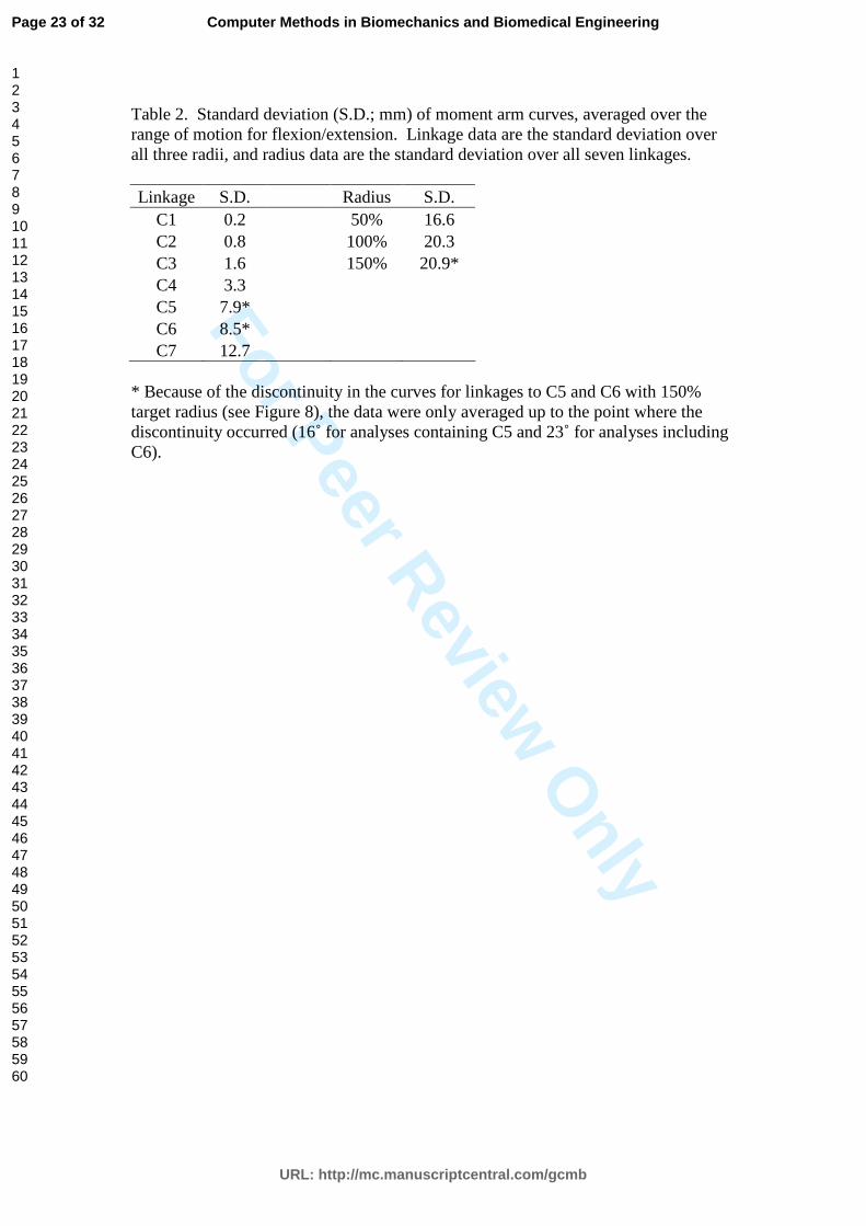
here for the semispinalis capitis muscle (Figure 1), one of the major extensors of the
head and neck.
2.1.2 Modelled paths and wrapping surface definition
Subject-specific static models were created using Software for Interactive
Musculoskeletal Modeling (SIMM; Musculographics, Santa Rosa, CA). These
models were designed to reproduce the subject’s musculoskeletal geometry in each of
the seven head postures from the MRI scans, and were used (1) to define and apply
wrapping surfaces and (2) to evaluate the accuracy of the modelled muscle paths
compared to the centroid path from MRI (Figure 1). For visualization purposes (e.g.,
Figures 1 and 3), generic model bones were implemented in the model. To recreate
the subject’s posture from the MRI scans, the model’s vertebrae and skull were placed
so that they had the same position and orientation with respect to the sternal notch as
the bones in the sagittal MR images. The vertebral position and orientation were
Page 6 of 32
URL: http://mc.manuscriptcentral.com/gcmb
Computer Methods in Biomechanics and Biomedical Engineering
123456789101112131415161718192021222324252627282930313233343536373839404142434445464748495051525354555657585960

For Peer Review O
nly
B. Suderman et al.
7
defined in terms of a local coordinate system with its origin at the centroid of the four
corners of the vertebral body in the sagittal plane. The midpoints of the upper and
lower vertebral endplates were identified, and the y-axis was aligned with the two
midpoints, positive in the superior (cranial) direction. The x-axis was oriented
perpendicular to the y-axis in the sagittal plane and was positive anteriorly; and the z-
axis was the cross product of the y-axis and x-axis vectors, positive to the right.
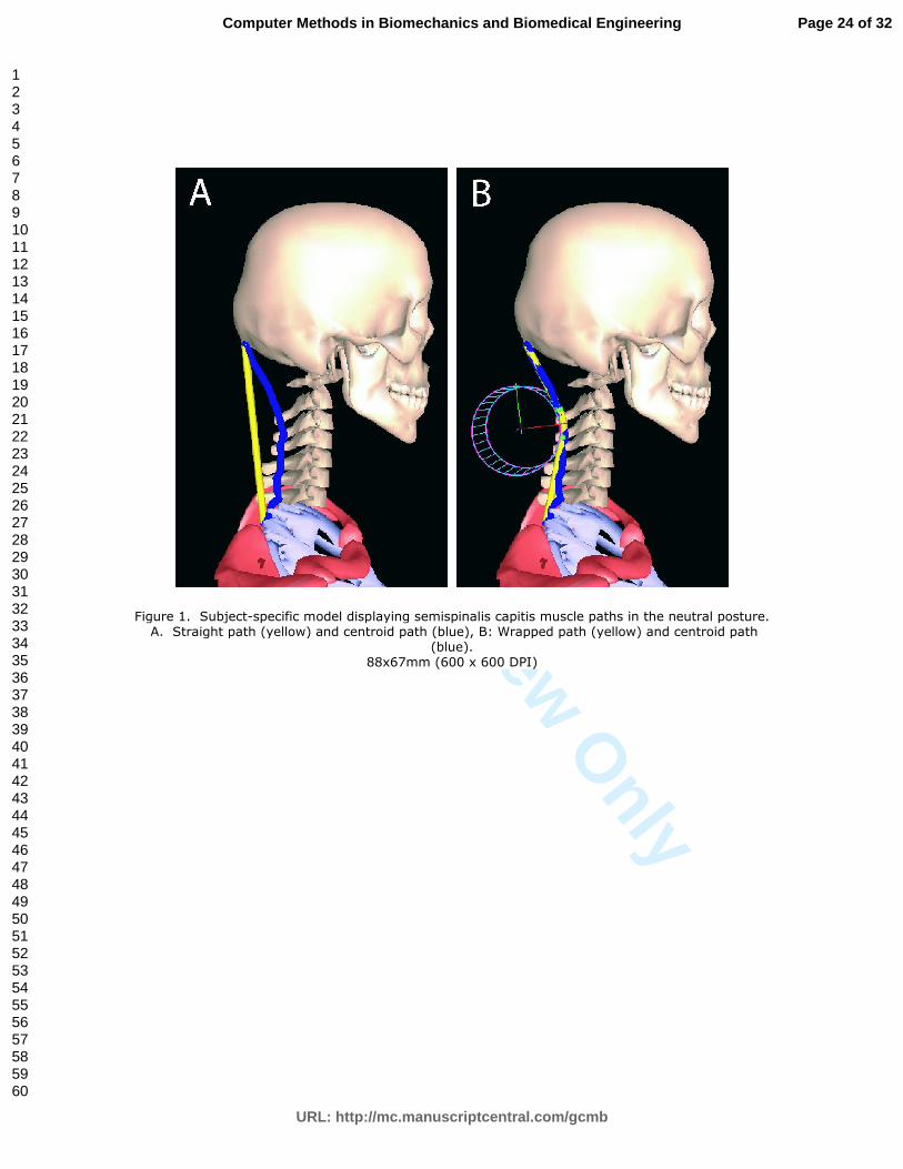
Cylindrical wrapping surfaces were defined using the neutral posture data,
such that the straight path was constrained to be closer to the centroid path (Figure 1
and Figure 2A). First, the point along the centroid path which was furthest away from
the straight path was identified; we assumed that this was the location where the
straight path needed greatest adjustment. The x-axis of the cylindrical wrapping
surface was defined as the perpendicular direction from the straight path to the
furthest point on the centroid path; the y-axis was parallel to the straight path; and the
z-axis (long axis of the cylinder) was mutually perpendicular. Although radius was
varied in the sensitivity analysis (below), the target radius of the cylinder was defined
as the distance from the straight path to the furthest centroid point. The centre of the
cylinder was placed such that the surface of the cylinder touched the furthest centroid
point, i.e., at a distance equal to the cylinder radius from the furthest centroid point to
the straight path along the x-axis (Figure 2).
The wrapping surface parameters - cylinder orientation, radius, and centre,
were defined separately for the left and right muscles. The values for left and right
were averaged and mirrored to create symmetric wrapping surfaces about the mid-
sagittal plane, which were applied to both the left and right muscles for analysis of the
resulting muscle path and moment arm estimates. This step followed from our
assumption that the model should be symmetric; averaging the wrapping surface
Page 7 of 32
URL: http://mc.manuscriptcentral.com/gcmb
Computer Methods in Biomechanics and Biomedical Engineering
123456789101112131415161718192021222324252627282930313233343536373839404142434445464748495051525354555657585960
For Peer Review O
nly
Computer Methods in Biomechanics and Biomedical Engineering
8
parameters would account for any asymmetries in the musculoskeletal geometry and
possible tracing errors.
2.1.3 Wrapping surface parameter evaluation
We assessed the effect of varying two properties of the wrapping surface on muscle
path and moment arm: (1) the radius and centre location of the cylinder (which were
varied together), and (2) the vertebral segment to which the wrapping surface is
linked, which defines the wrapping surface kinematics.
Radius. We tested three different values of cylinder radius (the target radius (rt),
0.5*rt, and 1.5*rt; Figure 2B); each radius had a different centre translated along the
cylinder’s x-axis so the outer surface of the cylinder was touching the same point
(furthest centroid from the straight path). A large radius often provides a better fit to
the centroid path (as measured by the error metric defined below); this phenomenon is
illustrated schematically (in 2 dimensions) in Figure 2B. However, if a wrapping
surface is too large, the endpoint of the muscle may fall within the surface in extreme
postures, and the path will not wrap around the surface (seen in some moment arm
curves in the Results).
Kinematic linkage. We also assessed the effect of linking wrapping surfaces to
different vertebral segments. The wrapping surface was initially defined in a global
coordinate system with the model in the subject’s neutral posture. We then defined
the wrapping surface relative to each of the vertebral local coordinate systems (C1-
C7; one at a time) and rigidly fixed it to that vertebra as the model was placed in other
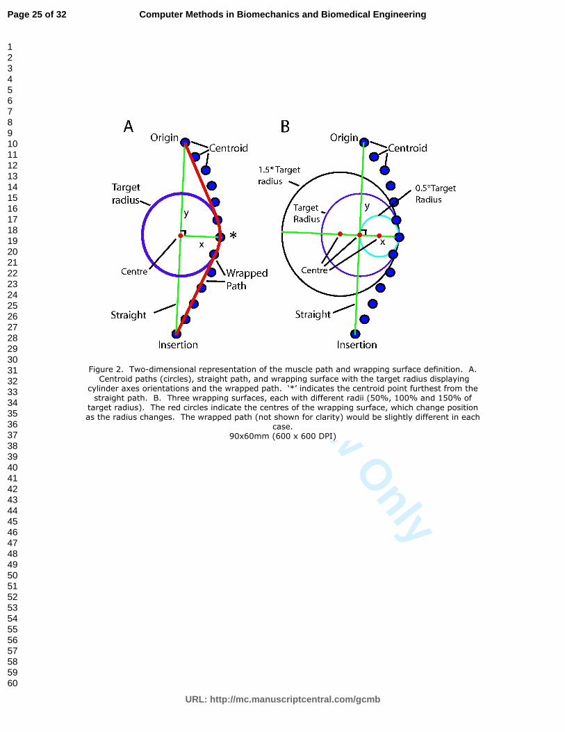
postures. The vertebral segment chosen for linkage does not change the muscle path
in the neutral posture (Figure 3B; compare top and bottom images), but changes how
the cylinder rotates in other postures, potentially affecting the muscle path and
moment arm over the range of motion (Figures 3A & 3C).
Page 8 of 32
URL: http://mc.manuscriptcentral.com/gcmb
Computer Methods in Biomechanics and Biomedical Engineering
123456789101112131415161718192021222324252627282930313233343536373839404142434445464748495051525354555657585960
For Peer Review O
nly
B. Suderman et al.
9
2.1.3 Muscle path evaluation
The quality of the fit between the model wrapped path and MRI centroid path is
measured by the error metric. In our previous study, we defined the error metric
(EM) as the average deviation of the centroid path from the wrapped path, measured
at each MRI slice (Vasavada et al. 2008).
Error metric was determined for all combinations of three radii and seven
vertebral linkages over all seven postures. For a given combination of radius and
linkage, the average error metric over all postures was evaluated. We chose the
wrapping surface that minimized average error metric to represent the most accurate
muscle path in multiple postures. The effect of radius and vertebral linkage on error
metric was analyzed using a two-way ANOVA.
1.22.2 Moment arm
2.2.1 Generic kinematic model
Information about intervertebral kinematics between postures, which is necessary for
estimating moment arm, was not available from the static MRI scans. Thus, a generic
kinematic model of a 50th percentile male head and neck musculoskeletal system
(Vasavada et al. 1998) was utilized to evaluate the effect of muscle wrapping on
moment arms. At each of the eight intervertebral joints between the skull and T1, the
axis of rotation for flexion-extension motions was defined according to radiographic
studies (Amevo et al. 1991). The amount of motion occurring at each intervertebral
joint was constrained to be a function of one angle (generalized coordinate) – the
angle of the head relative to the trunk.
In the generic model, the straight line path of the semispinalis capitis muscle
was defined by its attachments relative to bony landmarks on the skull (midway
between the superior and inferior nuchal lines) and vertebra (transverse process of
Page 9 of 32
URL: http://mc.manuscriptcentral.com/gcmb
Computer Methods in Biomechanics and Biomedical Engineering
123456789101112131415161718192021222324252627282930313233343536373839404142434445464748495051525354555657585960

For Peer Review O
nly
Computer Methods in Biomechanics and Biomedical Engineering
10
T1). Although the semispinalis capitis has attachments to other vertebrae, its path
was simplified for this analysis as the position of the other vertebral attachments (or
muscle subvolumes) could not be determined from the MRI scans in the subject-
specific model. Wrapping surfaces defined relative to the vertebral local coordinate
system in the subject-specific static model were applied to the kinematic model.
2.2.2 Definitions of moment arm
In the musculoskeletal modelling software, the moment arm was calculated
kinematically using the tendon excursion method, equivalent to the change in
musculotendon length with respect to head angle:
�� ���
�� . (1)
We also calculated the moment arm of the modelled path using a geometric method.
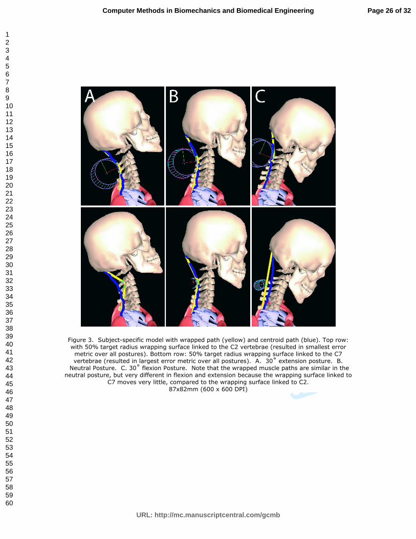
The instantaneous axis of rotation (IAR) of the skull with respect to the torso was
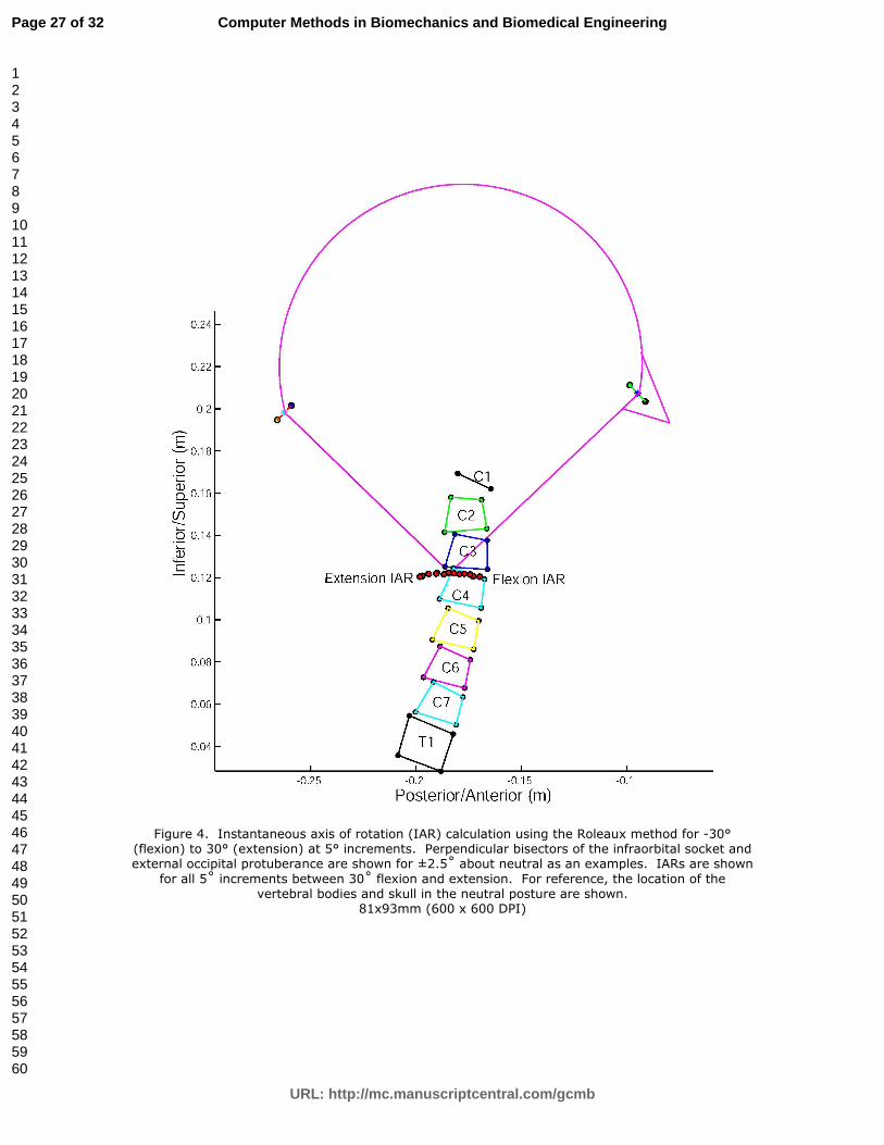
calculated using the Rouleaux method (Panjabi 1979). Coordinates of the infraorbital
socket and the external occipital protuberance on the skull of the kinematic model
were recorded at ±2.5° of the desired position, and the perpendicular bisectors of the
lines connecting those points were generated. The IAR was then calculated from 30°
flexion to 30° extension at 5° increments as the intersection of the perpendicular
bisectors (Figure 4). At each angle, the extension moment arm was determined as the
shortest distance in the sagittal plane from the straight or wrapped path to the IAR
(Wilson et al. 1999).
2.2.3 Moment arm evaluation
Both kinematic and geometric moment arms were calculated for the straight
and wrapped paths for sagittal plane (flexion-extension) motion, where semispinalis
capitis has its largest moment arms (Vasavada et al. 1998). Moment arm was
Page 10 of 32
URL: http://mc.manuscriptcentral.com/gcmb
Computer Methods in Biomechanics and Biomedical Engineering
123456789101112131415161718192021222324252627282930313233343536373839404142434445464748495051525354555657585960
For Peer Review O
nly
B. Suderman et al.
11
evaluated over a range of 30˚ flexion to 30˚ extension because the MRI data (subject-
specific model) covered that range of motion, even though the generic kinematic
model has a larger range of motion.
As with the evaluation of muscle path, we varied the radius and vertebral
linkage. All seven vertebral linkages (C1 to C7) were examined for each of the three
cylinder radii, resulting in 21 moment arm curves. Similar to the error metric
analysis, we performed two-way ANOVA tests on kinematic moment arm data to
investigate sensitivities to radius/centre position and vertebral linkage. Geometric
moment arms are only reported for the target radius with linkages to each vertebra;
one-way ANOVA tests were performed on geometric moment arm data to investigate
sensitivities to vertebral linkage. Paired t-tests were performed to compare kinematic
and geometric moment arms at each vertebral linkage (for the target radius only).
23 Results
3.1 Error Metric
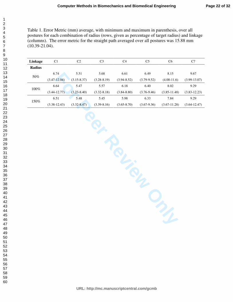
All implementations of wrapping surface radius/centre and vertebral linkage
improved the error metric from the straight path (Table 1); the average improvement
for all wrapping surface radii, linkages, and postures was 57% (from an average
straight path error metric of 15.88 mm to an average wrapped path error metric of
6.82 mm). Averaged over all postures, the lowest error metric was 5.45 mm,
occurring with the wrapping surface linked to C3 with 150% of the target radius.
With this combination (C3 linkage and 150% target radius), the error metric was
smallest (3.39 mm) in the flexion posture and largest (8.16 mm) in the lateral bending
posture for the contralateral muscle. All six of the lowest error metrics occurred for
kinematic linkages to C2 or C3.
Page 11 of 32
URL: http://mc.manuscriptcentral.com/gcmb
Computer Methods in Biomechanics and Biomedical Engineering
123456789101112131415161718192021222324252627282930313233343536373839404142434445464748495051525354555657585960

For Peer Review O
nly
Computer Methods in Biomechanics and Biomedical Engineering
12
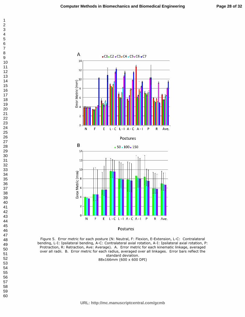
For a given wrapping surface radius, the error metric varied significantly
depending on the vertebral segment to which the wrapping surface was linked (Figure
5A; p = 0). However, for a given vertebral linkage, varying the wrapping surface
radius and centre did not significantly affect the error metric (Figure 5B; p = 0.80).
Error metric varied significantly with posture, and this variation was
influenced by linkage. For all linkages, the error metric was generally larger for axial
rotation and lateral bending (both contralateral and ipsilateral muscles). However, for
linkages to C6 or C7, the error metric was larger for all postures compared to linkages
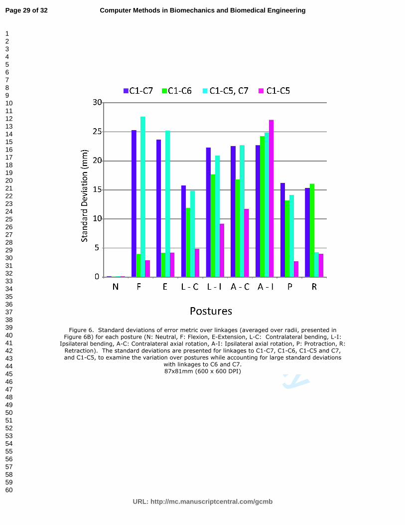
to other vertebrae. To separate the outlier values for linkages to C6 and C7, we
calculated the standard deviations of the error metric for individual postures using
different sets of vertebral linkages; all vertebrae (C1-C7), C1-C6 (leaving out C7),
C1-C5 plus C7 (leaving out C6), and C1-C5 (Figure 6). If we examine the standard
deviation for C1-C5 only (i.e., discount the large EM values for C6 and C7), axial
rotation had the largest variation over all linkages, followed by lateral bending for
both contralateral and ipsilateral muscles.
3.2 Moment Arm
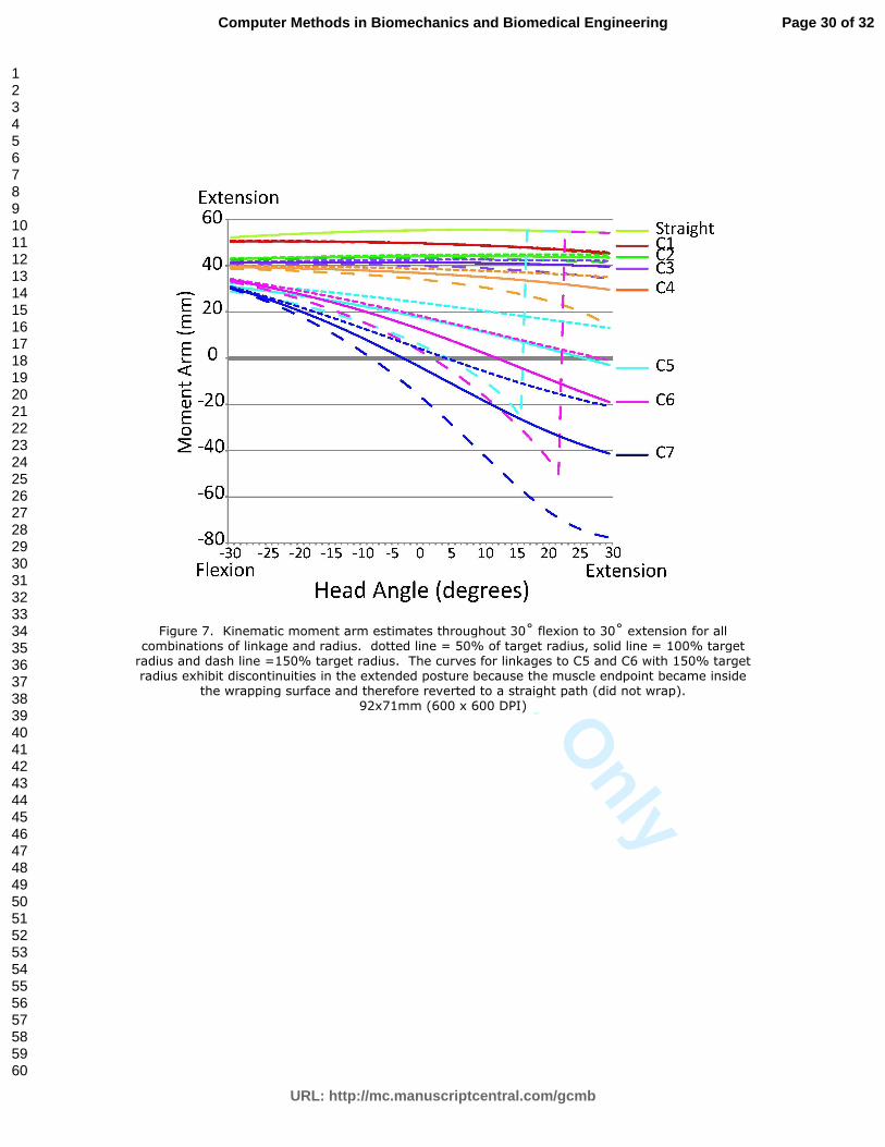
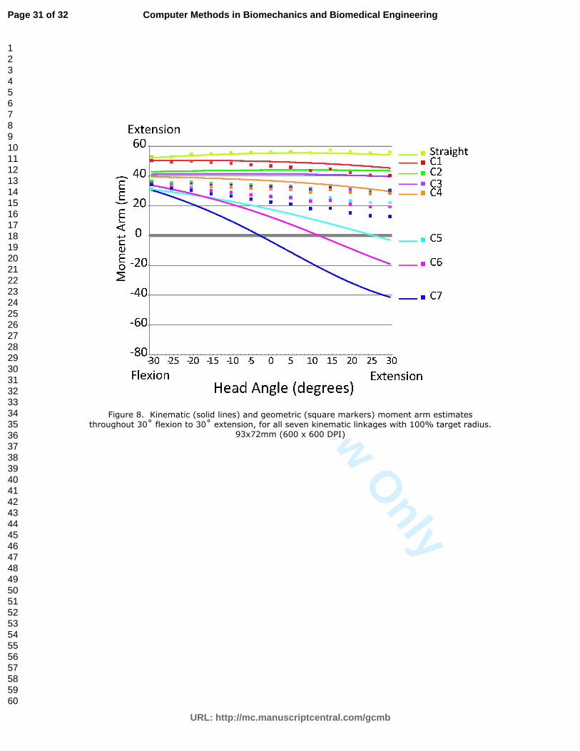
Moment arms for wrapped paths were smaller than those for straight paths
(Figures 7 and 8), whether calculated kinematically or geometrically. Moment arms
calculated using the kinematic method varied significantly with both radius and
kinematic linkage (p = 0 for both factors, two-way ANOVA). As radius increases,
moment arm values decrease (or become more negative at some angles with wrapping
surfaces linked to C5-C7).(Figure 7). Moment arms also have a wider range of values
with linkages to lower cervical vertebrae (Figure 7, Table 2). Over the range of
parameters we tested, the standard deviation of kinematic moment arm is larger for
the variation of vertebral linkage than for the variation of radius (Table 2). The
Page 12 of 32
URL: http://mc.manuscriptcentral.com/gcmb
Computer Methods in Biomechanics and Biomedical Engineering
123456789101112131415161718192021222324252627282930313233343536373839404142434445464748495051525354555657585960
For Peer Review O
nly
B. Suderman et al.
13
geometric moment arm values were calculated for only one radius value, but these
moment arms also decrease significantly with linkages to lower cervical vertebrae
(Figure 8; p = 0, one-way ANOVA).
For each vertebral linkage, with the radius set to the target radius, kinematic
and geometric moment arms were significantly different (paired t-tests, p < 0.01). For
linkages to C1-C4, geometric moment arms have lower values compared to kinematic
moment arms (Figure 8). Kinematic moment arms for wrapping surfaces linked to
C5, C6 or C7 become negative when the head goes into extension, whereas the
geometric moment arms remain positive throughout the entire range of motion.
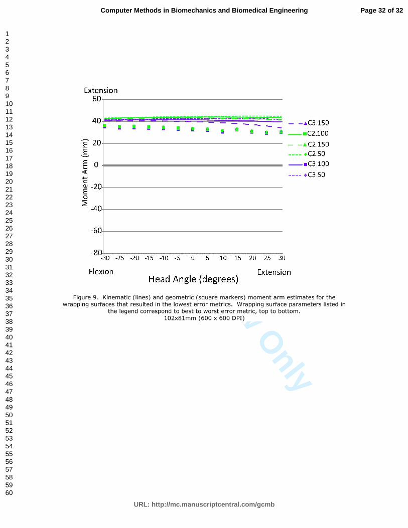
The muscle paths resulting in the smallest six error metrics (Figure 9) had
small standard deviation of the moment arm curves (1.9 mm). In contrast, muscle
paths resulting in the largest six error metrics had larger moment arm curve standard
deviation (11.8 mm).
4 Discussion
4.1 Muscle paths
The accuracy of neck muscle paths over a range of postures was not significantly
affected by the size and centre position of the wrapping surface. Altering the
vertebral segment to which the wrapping surface was linked significantly altered the
muscle path over a range of postures because each vertebra moved by a different
amount.
For the semispinalis capitis muscle, the best muscle paths (lowest error metric)
occurred with linkages to upper cervical vertebrae (C2 or C3), whereas the worst
paths (largest error metric) occurred with linkages to lower cervical vertebrae (C6 or
C7). The motion of the upper cervical vertebrae (in a global coordinate system) are a
cumulative sum of the motion of all vertebrae below it. Therefore, wrapping surfaces
Page 13 of 32
URL: http://mc.manuscriptcentral.com/gcmb
Computer Methods in Biomechanics and Biomedical Engineering
123456789101112131415161718192021222324252627282930313233343536373839404142434445464748495051525354555657585960
For Peer Review O
nly
Computer Methods in Biomechanics and Biomedical Engineering
14
linked to upper cervical vertebrae move a greater amount than those linked to lower
vertebrae (c.f., Figure 3). For C2 and C3, the vertebral kinematics appeared to be
appropriate to match centroid paths, but wrapping surfaces linked to C1 had higher
error metrics.
This work shows that, at least for the neck, evaluating muscle paths in
multiple postures is important to accurately represent the musculoskeletal anatomy.
In fact, the error metric varied very little in the neutral posture; the standard deviation
over all sets of wrapping surface parameters (radius and linkage) was 0.1 mm, making
it difficult to choose any set of wrapping surface parameters over the other. However,
the standard deviation of error metric over all postures was 2.3 mm, and it is clear that
some wrapping surface parameters provide a superior fit in non-neutral postures
(Figure 3).
As we found in our earlier study (Vasavada et al. 2008), modelled muscle
paths were least accurate in out-of-sagittal plane postures (i.e, lateral bending and
axial rotation). However, the wrapping surface parameters that resulted in the lowest
average error metric also resulted in the lowest maximum error metric (Table 1). In
this study, wrapping surfaces were defined in the neutral posture and evaluated in
other postures. For applications in which more accurate representation of muscle
paths in non-sagittal plane postures is important, it may be necessary to use these
other postures to define different wrapping surface parameters.
4.2 Moment arm
Moment arm varied significantly with both linkage and radius, but was more sensitive
to linkage. A surprising result of this study was the prediction of flexion moment
arms in extended postures by the kinematic method. This occurred for wrapping
Page 14 of 32
URL: http://mc.manuscriptcentral.com/gcmb
Computer Methods in Biomechanics and Biomedical Engineering
123456789101112131415161718192021222324252627282930313233343536373839404142434445464748495051525354555657585960
For Peer Review O
nly
B. Suderman et al.
15
surfaces linked to lower cervical vertebrae, C5-C7 (Figure 7). Because the lower
cervical vertebrae (and associated wrapping surface) did not move as much as upper
cervical vertebrae (cf. Figure 3), the muscle lengthened as the head extended.
According to the kinematic definition of moment arm (change in muscle-tendon
length vs. change in joint angle), this is a negative (flexion) moment arm. However,
the wrapping surface parameters which led to negative moment arms are clearly not
the appropriate geometry, as evidenced by their lack of correspondence to the muscle
path (Table 1 and Figure 3).
The semispinalis capitis may be an extreme example of moment arm
sensitivity to wrapping surface linkage. In other highly curved neck muscles, we also
see large variation in moment arm with different kinematic linkages. However, other
neck muscles do not appear to have the extreme changes in sign of moment arm as
seen in semispinalis capitis with linkages to C5-C7. It is important to recognize that
inappropriate wrapping surface kinematics may lead to incorrect muscle paths and
moment arms over a range of motion, even though the muscle paths are accurate in
the neutral posture.
We found differences in the moment arms calculated by a kinematic method
compared to those with a geometric method. Other studies have found that moment
arms calculated kinematically are larger than those calculated geometrically (Wilson
et al. 1999), but to our knowledge none have shown that the kinematic method results
in moment arms of opposite sign to the geometric method. Geometric estimates of
semispinalis capitis moment arm are positive (i.e., extension moment arms) for all
linkage and radius combinations. We believe the negative moment arm predicted in
some cases by the kinematic method is physically incorrect, but this may be due to
poor muscle path definition, rather than an error in the kinematic method. We also
Page 15 of 32
URL: http://mc.manuscriptcentral.com/gcmb
Computer Methods in Biomechanics and Biomedical Engineering
123456789101112131415161718192021222324252627282930313233343536373839404142434445464748495051525354555657585960
For Peer Review O
nly
Computer Methods in Biomechanics and Biomedical Engineering
16
found that moment arm estimates from the kinematic and geometric method agree for
straight paths and do not agree for curved paths. This may indicate that alternate
methods of calculating moment arms may need to be explored for curved paths.
The model-predicted moment arms have not been compared to experimentally
measured neck muscle moment arms, because to our knowledge these data are not
available in the literature. This study suggests that it is critical to measure neck
muscle moment arms by both the tendon excursion (kinematic) method and imaging
(geometric) method in cadavers, as neither method has been validated with curved
muscle paths experimentally. Although the tendon excursion method can only be
used in cadavers, imaging may also be used in vivo in humans.
We found that the wrapping surface parameters which produced the best fit to
muscle centroid path (i.e., had the lowest error metrics) resulted in more consistent
moment arm curves. Other studies have found that modelling the muscle path
accurately should result in the most accurate moment arm estimation (Arnold et al.
2000). Without experimental measurements of neck muscle moment arms for
comparison, we assume that the wrapping surfaces with the best fit to muscle centroid
path predict the most realistic moment arm values.
4.3 Considerations for selecting wrapping surface parameters
In this study, we also modified the method for selecting wrapping surface parameters
that was described in an earlier study (Vasavada et al. 2008). Previously, cylindrical
wrapping surfaces were oriented in the transverse plane when the head and neck were
in the neutral posture and linked to the nearest vertebra. In the current study, we
oriented the wrapping surface according to the direction of the greatest perpendicular
distance between the straight and centroid paths. By considering the three-
dimensional straight and centroid paths to define the wrapping surface and examining
Page 16 of 32
URL: http://mc.manuscriptcentral.com/gcmb
Computer Methods in Biomechanics and Biomedical Engineering
123456789101112131415161718192021222324252627282930313233343536373839404142434445464748495051525354555657585960
For Peer Review O
nly
B. Suderman et al.
17
linkages to different vertebrae, we were able to obtain only a slightly better fit to the
centroid path of semispinalis capitis (average error metric 5.45 mm vs. 5.60 mm).
However, the semispinalis capitis muscle is primarily oriented in a vertical plane, so
the wrapping surface orientation was similar for either method; therefore, this new
method may be more appropriate to define muscle paths for other neck muscles (e.g.,
trapezius), which have more complex paths that would require wrapping surfaces
placed in non-transverse planes.
Some of the issues raised in this study may be related to the fact that we used a
subject-specific model to define wrapping surfaces and evaluate muscle paths but a
generic model to calculate and evaluate moment arms. Moment arm variation with
linkage may have been larger because the geometry and kinematics of the generic
model were different from the subject-specific models. This may also explain
partially why radius did not affect muscle path (evaluated in the subject-specific
model) but did affect moment arm (evaluated in the generic model).
To compare the generic and subject-specific models, we also calculated
geometric moment arms from the subject-specific MRI data in the neutral posture.
Because it is known that IAR (and thus the geometric moment arm) can vary with the
angular increment used to calculate it, we used an IAR calculation from 60˚ range of
motion (MRI data were only available in 30˚ extension and 30˚ flexion postures). The
moment arm in neutral from the subject-specific MRI data was 22 mm, whereas the
average geometric moment arm for all kinematic linkages in the generic model was
31 mm.
5 Conclusions
We found that neck muscle paths and moment arms were significantly affected by the
parameters used to define wrapping surfaces. In particular, the vertebral body to
Page 17 of 32
URL: http://mc.manuscriptcentral.com/gcmb
Computer Methods in Biomechanics and Biomedical Engineering
123456789101112131415161718192021222324252627282930313233343536373839404142434445464748495051525354555657585960
For Peer Review O
nly
Computer Methods in Biomechanics and Biomedical Engineering
18
which a wrapping surface is linked is a critical parameter in the definition of wrapping
surfaces. However, wrapping surface parameters which resulted in a better match to
muscle paths also resulted in a smaller range of moment arm estimations. We urge
caution in selecting the vertebral body to which the wrapping surface is linked and
suggest that a range of postures be used to select appropriate wrapping surface
parameters.
Acknowledgements: We thank Richard Lasher and Travis Meyer. Supported by NSF
(CBET #0748303) and the Whitaker Foundation.
Page 18 of 32
URL: http://mc.manuscriptcentral.com/gcmb
Computer Methods in Biomechanics and Biomedical Engineering
123456789101112131415161718192021222324252627282930313233343536373839404142434445464748495051525354555657585960
For Peer Review O
nly
B. Suderman et al.
19
References
Arnold A, Salinas S, Asakawa D, Delp S. 2000. Accuracy of muscle moment arms
estimated from MRI-Based musculoskeletal models of the lower extremity. Computer
Aided Surgery. 5:108-119. Available
Murray WM, Arnold AS, Salinas S, Durbhakula MM, Buchanan TS, Delp SL. 1998.
Building Biomechanical models based on medical image data: an assessment of
model accuracy. Lecture Notes in Computer Science.539-549. Available
Garner B, Pandy M. 2000. The obstacle-set method for representing muscle paths in
musculoskeletal modeling. Computer Methods in Biomechanics and Biomedical
Engineering. 3(1):1-30. Available
Kruidhof J, Pandy M. 2006. Effect of muscle wrapping on model estimates of neck
muscle strength. Computer Methods in Biomechanics and Biomedical Engineering.
9(6):343-352. Available
Vasavada AN, Li S, Delp SL. 1998. Influence of muscle morphometry and moment
arms on the moment-generating capacity of human neck muscles. SPINE. 23(4):412-
421. Available
Jensen R, Davy D. 1975. An investigation of muscle lines of action about the hip: a
centroid line approach vs the straight line approach. Journal of Biomechanics.
8(2):103-110. Available
Vasavada AN, Lasher RA, Meyer TE, Lin DC. 2008. Defining and evaluating
wrapping surfaces for MRI-derived spinal muscle paths. Journal of Biomechanics.
41(7):1450-1457. Available
An KN, Takakashi K, Harrington TP, Chao EY. 1984. Determination of muscle
orientation and moment arms. J Biomech Eng. 106:280-282. Available
Wilson DL, Zhu Q, Duerk JL, Mansour JM, Kilgore K, Crago PE. 1999. Estimation
of tendon moment arms from three-dimensional magnetic resonance images. Annals
of Biomedical Engineering. 27(2):247-256. Available
Gordon CC, Churchill T, Clauser CE, Bradtmiller B, McConville JT, Walker RA.
1989. 1988 anthropometric survey of U.S. army personnel: methods and summary
statistics.
Amevo B, Worth D, Bogduk N. 1991. Instantaneaous axes of rotation of the typical
cervical motion segments: a study in normal volunteers. Clinical Biomechanics.
6(2):111-117. Available
Panjabi M. 1979. Centers and angles of rotation of body joints: a study of errors and
optimization. Journal of Biomechanics. 12(12):911-920. Available
Page 19 of 32
URL: http://mc.manuscriptcentral.com/gcmb
Computer Methods in Biomechanics and Biomedical Engineering
123456789101112131415161718192021222324252627282930313233343536373839404142434445464748495051525354555657585960
For Peer Review O
nly
Computer Methods in Biomechanics and Biomedical Engineering
20
Figure Captions
Figure 1. Subject-specific model displaying semispinalis capitis muscle paths in the
neutral posture. A. Straight path (yellow) and centroid path (blue), B: Wrapped path
(yellow) and centroid path (blue).
Figure 2. Two-dimensional representation of the muscle path and wrapping surface
definition. A. Centroid paths (circles), straight path, and wrapping surface with the
target radius displaying cylinder axes orientations and the wrapped path. ‘*’ indicates
the centroid point furthest from the straight path. B. Three wrapping surfaces, each
with different radii (50%, 100% and 150% of target radius). The red circles indicate
the centres of the wrapping surface, which change position as the radius changes. The
wrapped path (not shown for clarity) would be slightly different in each case.
Figure 3. Subject-specific model with wrapped path (yellow) and centroid path
(blue). Top row: with 50% target radius wrapping surface linked to the C2 vertebrae
(resulted in smallest error metric over all postures). Bottom row: 50% target radius
wrapping surface linked to the C7 vertebrae (resulted in largest error metric over all
postures). A. 30˚ extension posture. B. Neutral Posture. C. 30˚ flexion Posture.
Note that the wrapped muscle paths are similar in the neutral posture, but very
different in flexion and extension because the wrapping surface linked to C7 moves
very little, compared to the wrapping surface linked to C2.
Figure 4. Instantaneous axis of rotation (IAR) calculation using the Roleaux method
for -30° (flexion) to 30° (extension) at 5° increments. Perpendicular bisectors of the
infraorbital socket and external occipital protuberance are shown for ±2.5˚ about
neutral as an examples. IARs are shown for all 5˚ increments between 30˚ flexion and
extension. For reference, the location of the vertebral bodies and skull in the neutral
posture are shown.
Figure 5. Error metric for each posture (N: Neutral, F: Flexion, E-Extension, L-C:
Contralateral bending, L-I: Ipsilateral bending, A-C: Contralateral axial rotation, A-I:
Ipsilateral axial rotation, P: Protraction, R: Retraction, Ave: Average). A. Error
metric for each kinematic linkage, averaged over all radii. B. Error metric for each
radius, averaged over all linkages. Error bars reflect the standard deviation.
Figure 6. Standard deviations of error metric over linkages (averaged over radii,
presented in Figure 6B) for each posture (N: Neutral, F: Flexion, E-Extension, L-C:
Contralateral bending, L-I: Ipsilateral bending, A-C: Contralateral axial rotation, A-I:
Ipsilateral axial rotation, P: Protraction, R: Retraction). The standard deviations are
presented for linkages to C1-C7, C1-C6, C1-C5 and C7, and C1-C5, to examine the
variation over postures while accounting for large standard deviations with linkages to
C6 and C7.
Figure 7. Kinematic moment arm estimates throughout 30˚ flexion to 30˚ extension
for all combinations of linkage and radius. dotted line = 50% of target radius, solid
line = 100% target radius and dash line =150% target radius. The curves for linkages
to C5 and C6 with 150% target radius exhibit discontinuities in the extended posture
Page 20 of 32
URL: http://mc.manuscriptcentral.com/gcmb
Computer Methods in Biomechanics and Biomedical Engineering
123456789101112131415161718192021222324252627282930313233343536373839404142434445464748495051525354555657585960
For Peer Review O
nly
B. Suderman et al.
21
because the muscle endpoint became inside the wrapping surface and therefore
reverted to a straight path (did not wrap).
Figure 8. Kinematic (solid lines) and geometric (square markers) moment arm
estimates throughout 30˚ flexion to 30˚ extension, for all seven kinematic linkages
with 100% target radius.
Figure 9. Kinematic (lines) and geometric (square markers) moment arm estimates
for the wrapping surfaces that resulted in the lowest error metrics. Wrapping surface
parameters listed in the legend correspond to best to worst error metric, top to bottom.
Page 21 of 32
URL: http://mc.manuscriptcentral.com/gcmb
Computer Methods in Biomechanics and Biomedical Engineering
123456789101112131415161718192021222324252627282930313233343536373839404142434445464748495051525354555657585960
For Peer Review O
nly
Table 1. Error Metric (mm) average, with minimum and maximum in parenthesis, over all
postures for each combination of radius (rows, given as percentage of target radius) and linkage
(columns). The error metric for the straight path averaged over all postures was 15.88 mm
(10.39-21.04).
Linkage C1 C2 C3 C4 C5 C6 C7
Radius
6.74 5.51 5.68 6.61 6.49 8.15 9.67 50%
(3.47-12.04) (3.15-8.37) (3.28-8.19) (3.94-8.52) (3.79-9.52) (4.00-11.6) (3.99-13.07)
6.64 5.47 5.57 6.18 6.40 8.02 9.29 100%
(3.44-12.77) (3.23-8.40) (3.32-8.18) (3.84-8.80) (3.76-9.46) (3.85-11.48) (3.83-12.23)
6.51 5.48 5.45 5.98 6.33 7.84 9.29 150%
(3.38-12.43) (3.32-8.47) (3.39-8.16) (3.65-8.70) (3.67-9.36) (3.67-11.28) (3.64-12.47)
Page 22 of 32
URL: http://mc.manuscriptcentral.com/gcmb
Computer Methods in Biomechanics and Biomedical Engineering
123456789101112131415161718192021222324252627282930313233343536373839404142434445464748495051525354555657585960
For Peer Review O
nly
Table 2. Standard deviation (S.D.; mm) of moment arm curves, averaged over the range of motion for flexion/extension. Linkage data are the standard deviation over all three radii, and radius data are the standard deviation over all seven linkages. Linkage S.D. Radius S.D.
C1 0.2 50% 16.6 C2 0.8 100% 20.3 C3 1.6 150% 20.9* C4 3.3 C5 7.9* C6 8.5* C7 12.7
* Because of the discontinuity in the curves for linkages to C5 and C6 with 150% target radius (see Figure 8), the data were only averaged up to the point where the discontinuity occurred (16˚ for analyses containing C5 and 23˚ for analyses including C6).
Page 23 of 32
URL: http://mc.manuscriptcentral.com/gcmb
Computer Methods in Biomechanics and Biomedical Engineering
123456789101112131415161718192021222324252627282930313233343536373839404142434445464748495051525354555657585960
For Peer Review O
nly
Figure 1. Subject-specific model displaying semispinalis capitis muscle paths in the neutral posture. A. Straight path (yellow) and centroid path (blue), B: Wrapped path (yellow) and centroid path
(blue). 88x67mm (600 x 600 DPI)
Page 24 of 32
URL: http://mc.manuscriptcentral.com/gcmb
Computer Methods in Biomechanics and Biomedical Engineering
123456789101112131415161718192021222324252627282930313233343536373839404142434445464748495051525354555657585960
For Peer Review O
nly
Figure 2. Two-dimensional representation of the muscle path and wrapping surface definition. A. Centroid paths (circles), straight path, and wrapping surface with the target radius displaying
cylinder axes orientations and the wrapped path. ‘*’ indicates the centroid point furthest from the straight path. B. Three wrapping surfaces, each with different radii (50%, 100% and 150% of
target radius). The red circles indicate the centres of the wrapping surface, which change position as the radius changes. The wrapped path (not shown for clarity) would be slightly different in each
case. 90x60mm (600 x 600 DPI)
Page 25 of 32
URL: http://mc.manuscriptcentral.com/gcmb
Computer Methods in Biomechanics and Biomedical Engineering
123456789101112131415161718192021222324252627282930313233343536373839404142434445464748495051525354555657585960
For Peer Review O
nly
Figure 3. Subject-specific model with wrapped path (yellow) and centroid path (blue). Top row: with 50% target radius wrapping surface linked to the C2 vertebrae (resulted in smallest error metric over all postures). Bottom row: 50% target radius wrapping surface linked to the C7 vertebrae (resulted in largest error metric over all postures). A. 30˚ extension posture. B.
Neutral Posture. C. 30˚ flexion Posture. Note that the wrapped muscle paths are similar in the neutral posture, but very different in flexion and extension because the wrapping surface linked to
C7 moves very little, compared to the wrapping surface linked to C2. 87x82mm (600 x 600 DPI)
Page 26 of 32
URL: http://mc.manuscriptcentral.com/gcmb
Computer Methods in Biomechanics and Biomedical Engineering
123456789101112131415161718192021222324252627282930313233343536373839404142434445464748495051525354555657585960
For Peer Review O
nly
Figure 4. Instantaneous axis of rotation (IAR) calculation using the Roleaux method for -30° (flexion) to 30° (extension) at 5° increments. Perpendicular bisectors of the infraorbital socket and external occipital protuberance are shown for ±2.5˚ about neutral as an examples. IARs are shown
for all 5˚ increments between 30˚ flexion and extension. For reference, the location of the vertebral bodies and skull in the neutral posture are shown.
81x93mm (600 x 600 DPI)
Page 27 of 32
URL: http://mc.manuscriptcentral.com/gcmb
Computer Methods in Biomechanics and Biomedical Engineering
123456789101112131415161718192021222324252627282930313233343536373839404142434445464748495051525354555657585960
For Peer Review O
nly
Figure 5. Error metric for each posture (N: Neutral, F: Flexion, E-Extension, L-C: Contralateral bending, L-I: Ipsilateral bending, A-C: Contralateral axial rotation, A-I: Ipsilateral axial rotation, P: Protraction, R: Retraction, Ave: Average). A. Error metric for each kinematic linkage, averaged over all radii. B. Error metric for each radius, averaged over all linkages. Error bars reflect the
standard deviation. 88x166mm (600 x 600 DPI)
Page 28 of 32
URL: http://mc.manuscriptcentral.com/gcmb
Computer Methods in Biomechanics and Biomedical Engineering
123456789101112131415161718192021222324252627282930313233343536373839404142434445464748495051525354555657585960
For Peer Review O
nly
Figure 6. Standard deviations of error metric over linkages (averaged over radii, presented in Figure 6B) for each posture (N: Neutral, F: Flexion, E-Extension, L-C: Contralateral bending, L-I:
Ipsilateral bending, A-C: Contralateral axial rotation, A-I: Ipsilateral axial rotation, P: Protraction, R: Retraction). The standard deviations are presented for linkages to C1-C7, C1-C6, C1-C5 and C7, and C1-C5, to examine the variation over postures while accounting for large standard deviations
with linkages to C6 and C7. 87x81mm (600 x 600 DPI)
Page 29 of 32
URL: http://mc.manuscriptcentral.com/gcmb
Computer Methods in Biomechanics and Biomedical Engineering
123456789101112131415161718192021222324252627282930313233343536373839404142434445464748495051525354555657585960
For Peer Review O
nly
Figure 7. Kinematic moment arm estimates throughout 30˚ flexion to 30˚ extension for all combinations of linkage and radius. dotted line = 50% of target radius, solid line = 100% target radius and dash line =150% target radius. The curves for linkages to C5 and C6 with 150% target radius exhibit discontinuities in the extended posture because the muscle endpoint became inside
the wrapping surface and therefore reverted to a straight path (did not wrap). 92x71mm (600 x 600 DPI)
Page 30 of 32
URL: http://mc.manuscriptcentral.com/gcmb
Computer Methods in Biomechanics and Biomedical Engineering
123456789101112131415161718192021222324252627282930313233343536373839404142434445464748495051525354555657585960
For Peer Review O
nly
Figure 8. Kinematic (solid lines) and geometric (square markers) moment arm estimates throughout 30˚ flexion to 30˚ extension, for all seven kinematic linkages with 100% target radius.
93x72mm (600 x 600 DPI)
Page 31 of 32
URL: http://mc.manuscriptcentral.com/gcmb
Computer Methods in Biomechanics and Biomedical Engineering
123456789101112131415161718192021222324252627282930313233343536373839404142434445464748495051525354555657585960
For Peer Review O
nly
Figure 9. Kinematic (lines) and geometric (square markers) moment arm estimates for the wrapping surfaces that resulted in the lowest error metrics. Wrapping surface parameters listed in
the legend correspond to best to worst error metric, top to bottom. 102x81mm (600 x 600 DPI)
Page 32 of 32
URL: http://mc.manuscriptcentral.com/gcmb
Computer Methods in Biomechanics and Biomedical Engineering
123456789101112131415161718192021222324252627282930313233343536373839404142434445464748495051525354555657585960