Embed Size (px)
Citation preview
1
FriendlyPanels Software
TWO CESSNA 675 AND 675 AMPHIBIAN AIRCRAFTS Aspen EFD 1000/500 EQUIPMENT THREE LIVERIES FOR EACH AIRCRAFT
For Microsoft ® Flight Simulator FSX
© 2010 FriendlyPanels. All right reserved

2
Table of Contents
1. Introduction 2. Requirements 3. Installing the aircrafts 4. Aircrafts Specifications sumary 5. Screenshots 6. Gauges
6.1 BENDIX KR 87 ADF 6.2 BENDIX KT 76C TRANSPONDER 6.3 BENDIX KX165A NAV-COM RADIO 6.4 BENDIX KFC 225 AUTOPILOT 6.5 DAVTRON DIGITAL CLOCK M877
7. Technical support
NOTE: GARMIN GNS 430, ASPEN EFD 1000 and EFD 500 Manuals are in separate documents, they are not included in this one.
3
1. Introduction Thank you for purchasing these Cessna Caravan 675 Aircraft, ASPEN EFD 1000/500 version. Here you will find the installing instructions of the product, and the description and user instructions of the gauges for the panels included in this Pack for FSX. Remember that GARMIN GNS 430, ASPEN EFD 1000 and EFD 500 Manuals are in separate documents, they are not included in this one. This pack includes the excellent ASPEN EFD 1000/500 navigation equipment and a Garmin GNS430. We have developed the 2D panels for these planes under a simple philosophy: panels in which you can see, read and handle as many gauges as a medium quality monitor screen allows, using the minimum number of windows, keeping a very good readability with a gauges layout as real as possible. Concerning the aircraft 3D model, you’ll find realistic movements of essential parts (ailerons, flaps, rudder, elevator, gear, doors, etc…) and a complete VC (in which you can manage all the gauges too) and passengers cabin. We try to avoid things not very useful which reduce substantially the frame rate in their respective views. Please, read this document entirely.
---oOo---
2. Requirements
This software requires Windows XP or later with at least SP1 and .Net Framework 1.1 and a screen resolution of 1024 x 768 or higher (1240 x 1024 recommended). No other special requirements are needed.
---oOo---
3. Installing the aircrafts Run the installation program and follow the indicated steps. You'll find your new planes under Manufacturer: FriendlyPanels.
---oOo---

4
4. Aircrafts specifications sumary With the same horsepower as the Grand Caravan, Cessna's Caravan 675 offers you all the excellent performance, rugged durability, and legendary reliability that have made Caravans great. With a maximum useful load of 4,110 pounds and a cruise speed of 186 knots, the 675 will move mountains in record time. The ASPEN EFD equipment included in this version is designed to replace traditional, mechanical primary flight instruments and much more.
With as few as four passengers, Caravan can beat the cost of airline travel. That makes it a natural for personal use or transporting company personnel.
Cessna Caravan 675 Cessna Caravan Amphibian Cruise Speed (10,000 ft) kts/km: 186/344 Engine: PT6A-114A Propeller: 3-Bladed, Constant Speed, Full Feathering, Reversible Maximum Range (10,000 ft): 932 nm / 1726 km Certified Ceiling ft/m: 25,000/7,620 Fuel Capacity gal/lbs: 335/2,248 Standard Empty Weight lbs/kg: 3,990/1,810 Maximum Weights lbs/kg:
Ramp 8,035/3,645 Takeoff Weight: 8,000 lb / 3,629 kg Landing Weight: 7,800 lb / 3,539 kg
Cabin (Aft of Pilot Area): Length ft/m 12.7/3.7 Height ft/m 4.3/1.3 Width ft/m 5.2/1.6 Volume cu ft/cu m 254/7.2
Length: 37.6’ Wingspan: 52.1’ Height:14.8’ Max Seating FAR 23/Other: 11/14 Maximum Useful Load lbs/kg: 4045/1835 Takeoff S.L. ISA:
Ground Roll ft/m 1,100/335 50-ft Obs. ft/m 2,000/610
Landing S.L.: Ground Roll ft/m 745/227 50-ft Obs. ft/m 1,655/504
S.L. Rate of Climb fpm/mpm: 1,234/376 Stall Speed (Ldg) kts/km: 61/113 SHP: 675
Cruise Speed (10,000 ft) kts/km: 163/302 Engine: PT6A-114A Propeller: 3-Bladed, Constant Speed, Full Feathering, Reversible Maximum Range (10,000 ft): 855 nm / 1,583 km Certified Ceiling ft/m: 20,000/6,069 Fuel Capacity gal/lbs: 335/2,248 Standard Empty Weight lbs/kg: 4,895/2,220 Maximum Weights lbs/kg:
Ramp 8,035/3,645 Takeoff: 8,000/3,629 Landing: 7,800/3,538
Cabin (Aft of Pilot Area): Length ft/m 12.7/3.7 Height ft/m 4.3/1.2 Width ft/m 5.2/1.6 Volume cu ft/cu m 254/7.2
Length: 38.9’ Wingspan: 52.1’ Height:18.2’ Max Seating FAR 23/Other: 11/14 Maximum Useful Load lbs/kg: 3,140/1,424 Takeoff S.L. ISA:
Ground Roll ft/m 1,920/585 50-ft Obs. ft/m 3,455/1053 Water run ft/m: 2.025/617
Landing S.L.: Ground Roll ft/m 1,045/319 50-ft Obs. ft/m 1,935/590 Water run ft/m: 1.045/319
S.L. Rate of Climb fpm/mpm: 823/251 Stall Speed (Ldg) kts/km: 59/109 SHP: 675

5
5. Some Screenshots
Cessna Caravan 675
Cessna Caravan 675 Amphibian

6
Cessna 675 EFD 2D panel
Cessna 675 EFD 2D panel, some pop-up windows

7
Cessna 675 EFD Virtual cockpit
Cessna 675 EFD Virtual cockpit at night

8
6. Gauges There are some areas to click on to show different pop-up windows, besides the simicons:
1. The area (1) shows the 2D panel landing 2. The area (2) toggles engines instruments, as shown below
3. The area (3) shows the EFD 1000/500 pop up window 4. The area (4) shows the radio stack pop up window 5. Test panel annunciator
About Virtual Cockpit If you usually use just Virtual Cockpit while flying, there are a couple of areas in VC that allow you to hide the yokes (pilot and co-pilot) so it’s easier to access some areas in VC. See the pictures below:
Clicking areas to hide yokes

9
Virtual cockpit pilot’s side hiding the yoke
Remember that, if you’re flying in VC mode you can easily access all important parts that control plane and systems using quick access keyboard keys: While in VC press “A” key repeatedly:
1. Once: Right Seat 2. Twice: Radios 3. Three times: Engine Controls, trims, etc… 4. Four times: main switches.

10
6.1 BENDIX KR 87 ADF
The Bendix KR 87 ADF has two knobs and five buttons. It displays active and stand by frequencies and integrates two timers. 6.1.1 Clicking areas
1. ADF / ANT modes. This version displays ADF station ident. 2. BFO mode (just the letters) 3. In frequency mode transfer stand by frequency to active. Returns to frequency mode from timers modes. 4. Go into timers mode. 5 and 6. Controls timers modes (described below). 7. On Off 8, 13, 14. Decrements frequency 9. Increments fractal frequency 10, 11, 12. Increments frequency 6.1.2 Display modes Frequency mode
Use knob and swap button to manage this screen. FLT timer Mode
From frequency mode push FLT/SET button once to go into this mode. This timer begins to count when you turn on the gauge and stops when you turn it off.

11
ET timer Mode
From frequency mode push FLT/SET button twice to go into this mode. This timer starts to count when you turn on the gauge, but you can control it. Clicking on SET/RST button once stops the timer. When it is stopped clicking again reset the timer and starts to count from zero. Clicking to the right of the button (area 7 above) will reset it to zero and ET begin to blink, you can use the knob to set a countdown (up to 59 minutes and 59 seconds), push SET/RST to start the countdown. After the countdown timer reaches zero, the counter will come up, whatever the mode you are in, and will begin to count upwards indefinitely while flashing for a few seconds, returning then to the mode you were before, if it was different. The Audio Alert is then sounded

12
6.2 BENDIX KT 76C TRANSPONDER
The Bendix KT 76 C Transponder has one knob and eleven buttons. 6.2.1 Clicking and display areas
1 to 8. ATCRBS Code Selector Knobs 9. Clear button 10. VFR Button 11 and 12. Function Selector Knob 13. Ident Pushbutton A. Ident Push button B. Encoding Altimeter Altitude Window C. Mode Annunciation and Reply Indicator D. Ident Window 6.2.2 Operation The KT 76 C display and operation are the same as KT 70 described above. There’s not GND function in the KT 76 C. The code is now set by 0 – 7 buttons. First time you click one of these buttons the first code number is highlighted. Push the button number you want to place here and the next number will be highlighted, this figure can now be set with a number button and so on. CLR button allows you to get back one place and correct a number.
13
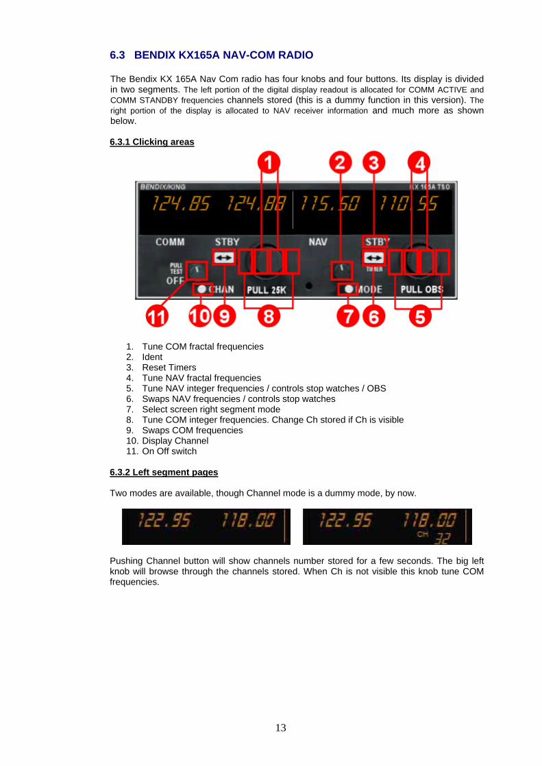
6.3 BENDIX KX165A NAV-COM RADIO The Bendix KX 165A Nav Com radio has four knobs and four buttons. Its display is divided in two segments. The left portion of the digital display readout is allocated for COMM ACTIVE and COMM STANDBY frequencies channels stored (this is a dummy function in this version). The right portion of the display is allocated to NAV receiver information and much more as shown below. 6.3.1 Clicking areas
1. Tune COM fractal frequencies 2. Ident 3. Reset Timers 4. Tune NAV fractal frequencies 5. Tune NAV integer frequencies / controls stop watches / OBS 6. Swaps NAV frequencies / controls stop watches 7. Select screen right segment mode 8. Tune COM integer frequencies. Change Ch stored if Ch is visible 9. Swaps COM frequencies 10. Display Channel 11. On Off switch
6.3.2 Left segment pages Two modes are available, though Channel mode is a dummy mode, by now.
Pushing Channel button will show channels number stored for a few seconds. The big left knob will browse through the channels stored. When Ch is not visible this knob tune COM frequencies.

14
6.3.3 Right segment pages The right segment of the screen can display 9 different modes; you can browse with the MODE button. ACTIVE / STAND BY mode
In this mode you can tune stby frequency with the right knob and swap frequencies with the transfer button ACTIVE / CDI mode
Pushing MODE button will take you to this mode. The vertical “needle” moves side to side similar to a mechanical CDI. When the needle is centred, the aircraft is on the selected OBS course. When the active frequency is tuned to a VOR frequency, the centre of the CDI scale displays the “TO” or “FROM” indicator. The CDI needle may be automatically centred with a “TO” indication clicking on centre of the knob. The CDI is displayed on the line below the frequency/OBS. When the ACTIVE frequency is tuned to a VOR frequency, the standby frequency area is replaced by a three digit OBS (Omni Bearing Selector) display. The desired OBS course can be selected with the right knob. When the ACTIVE window is tuned to a localizer frequency, the standby frequency area is replaced by “LOC”. When the received signal is too weak to ensure accuracy the display will flag. ACTIVE / BEARING mode
Pushing MODE once more causes the NAV display to go to bearing mode of operation, the right hand window of NAV display shows the bearing TO the station. ACTIVE / RADIAL mode
Another push of the MODE button will cause the NAV display to go from the ACTIVE/BEARING mode to the ACTIVE/RADIAL mode. The right hand window of NAV display shows the radial FROM the station. TIMER mode
Another mode button click will cause the unit to go into the TIMER mode. When the unit is turned on the elapsed timer begins counting upwards from zero. The timer can be stopped by pushing the NAV frequency swap button or reset to zero clicking on area 16 (see above) causing the ET on the display to flash. In this state the timer can be set as a countdown timer or the elapsed timer can be restarted. If you click on swap button again the counter will restart from zero. If you use the knob in the right side countdown timer can be set to the desired time (while ET is blinking) and then pushing the NAV swap button countdown will start. The top side of the knob selects minutes, the bottom side of the knob

15
selects seconds. After the countdown timer reaches zero, the counter will come up, whatever the mode you are in, and will begin to count upwards indefinitely while flashing for a few seconds, returning then to the mode you were before, if it was different. The Audio Alert is then sounded. ACTIVE / GPS modes The following GPS modes are not described in the KX 165 guide but we have considered useful to include this modes. You go into these modes pushing MODE button as well.
GPS CDI and desired track
Next waypoint distance and ident
Bearing to next waypoint distance and ident
Next waypoint ident ETE and ETA

16
6.4 BENDIX KFC 225 AUTOPILOT
The Bendix KFC 225 AUTOPILOT has one knob and twelve bottons. 6.4.1 Clicking areas
1. Yaw damper (if installed) 2. AP on off 3. Flight director (if installed) 4, 5, 6, 7. AP programs: Heading hold, Nav, Approach, Backcourse 8. Acquire current altitude 9 and 14. Decreases / increases vertical speed 10 and 11. Decreases / increases altitude hold 12. Displays current vertical speed 13. Intercepts altitude selected (knob 10 / 11) 6.4.2 Operation AUTOPILOT ENGAGE/DISENGAGE (AP) BUTTON When pressed, engages the flight director, autopilot and yaw damper (if installed). If the flight director is not already engaged, the system will engage into the basic wings level (ROL) and pitch (PIT) attitude hold modes. The pitch attitude maintained will be the pitch attitude present at the moment of AP button press. When pressed again, will disengage the autopilot. FLIGHT DIRECTOR (FD) MODE SELECTOR BUTTON When pressed will engage the flight director, if installed, into the basic roll (ROL) mode which functions as a wing leveler, and into the pitch attitude (PIT) hold mode, if it’s not installed, it acts like AP button if AP is not active and has no effect in any other circumstances. The pitch attitude maintained will be the pitch attitude present at the moment of FD button press. When pressed again will disengage the flight director. HEADING (HDG) MODE SELECTOR BUTTON When pressed, will engage the Heading mode, which commands the airplane to turn to and maintain the heading selected by the heading bug on the HSI. A new heading may be selected at any time and will result in the airplane turning to the new heading. Button can also be used to toggle between HDG and ROL modes. This button will engage the flight director, if installed.

17
NAVIGATION (NAV) MODE SELECTOR BUTTON When pressed, will arm the navigation mode. The mode provides automatic beam capture and tracking of VOR. NAV mode is recommended for en route navigation tracking. If pressed when NAV mode is either armed or coupled, will disengage the mode. This button will engage the flight director. APPROACH (APR) MODE SELECTOR BUTTON When pressed, will arm the Approach mode. This mode provides automatic beam capture and tracking of or LOC with Glideslope (GS) on an ILS. APR ARM will annunciate. If pressed when APR mode is either armed or coupled, will disengage the mode. This button will engage the flight director. BACK COURSE APPROACH (REV) MODE SELECTOR BUTTON When pressed, will select the back course approach mode. This mode functions similarly to the approach mode except that the autopilot response to LOC signals is reversed and glideslope is inhibited. This button will engage the flight director. ALTITUDE HOLD (ALT) MODE SELECT BUTTON When pressed, will engage the Altitude Hold mode. The altitude maintained is the altitude at the moment the ALT button is pressed. If pressed when ALT hold mode is engaged, will disengage the mode, defaulting to PIT mode. This button will engage the flight director. VERTICAL SPEED (UP/DN) BUTTONS The initial button press will bring up the commanded vertical speed in the display. Subsequent immediate button presses will increment the vertical speed command either up or down at the rate of 100 ft/min per button press. ROTARY KNOB Used to set the altitude alerter/altitude preselect reference altitude. Changes reference by 100’s of feet. If the flight director is engaged, will automatically arm a preselect altitude hold capture. VERTICAL SPEED (VS) MODE SELECTOR BUTTON When pressed bring up the commanded vertical speed in the display. It doesn’t capture VS in this version. ALTITUDE ARM (ARM) BUTTON When pressed will toggle altitude arming on or off. When ALT ARM is annunciated, the automatic flight control system will capture the altitude displayed in the Altitude Alerter/Vertical Speed Display (providedthe aircraft is climbing or descending to the displayed altitude). Note that the alerter functions are independent of the arming process thus providing full time alerting, even when the flight director is disengaged. This button will engage the flight director. 6.4.3 Display Here follows some AP explanation screenshots.
AP active no program engaged
Segment 1 displays the LNAV mode active, while segment 3 shows the mode armed if any. altitude alert (ALERT) annunciation Illuminates as a solid alert in the region from 1000 to 200 feet from the selected altitude if the airplane was previously outside of this region. Flashes for a few seconds the when the airplane reaches the selected altitude. An aural alert is associated with the visual alerting. This aural alert occurs 1,000 feet before a selected altitude while approaching it and 200 feet after leaving a selected altitude, and when the altitude is reached.

18
Segment 2 normally displays the selected altitude. The display indicates the reference vertical speed in FPM for 3 seconds after the VS button or the UP or DN button is pressed.
Here below follows how thw display changes in a tipycal sequence for an ILS approach.
Before LOC interception
LOC intercepted GS armed
LOC and GS intercepted

19
6.5 DAVTRON DIGITAL CLOCK M877
6.5.1 Operation The SEL button selects what is to be displayed, and the CTL button controls the timers. Pressing SEL sequentially selects to display Local Time, GMT , Flight Time, Elapsed Time, and back to Local Time. In the bottom segment of the display a dot points to the selected display LT, GMT, FT or ET.
FT starts counting when a valid groundspeed was first greater than 30 knots (typically during takeoff) and it will stops when that speed come down to less than 30 knots. ET starts counting when you click on control butoon while ET is selected (the red dot is above ET) When FT is being displaying ((the red dot is above FT) clicking twice the CTL button resets Flight Time, FT, back to zero. One more click will start it again. The CTL button also stops, resets and starts again Elapsed Time when clicked sequentially, if ET is selected.
Flight Time and Elapsed Time counts up to 59 minutes, 59 seconds, and then switches to hours and minutes.
7. TECHNICAL SUPPORT
If you have any question, please contact FrienlyPanels at:
Web page: www.friendlypanels.com
![[AWS Black Belt Online Seminar] · 2019. 5. 13. · fsx-OST0000_UUID 1182566272 4608 1182559616 0% /mnt/fsx[OST:0] fsx-OST0001_UUID 1182566272 4608 1182559616 0% /mnt/fsx[OST:1] fsx-OST0002_UUID](https://img.pdfslide.us/doc/110x75/5fe6a5cb0fac2d59b6113c25/aws-black-belt-online-seminar-2019-5-13-fsx-ost0000uuid-1182566272-4608.jpg)