Embed Size (px)
Citation preview

1 Kordis Media Co.,ltd.
Data Sheet NCB110X3
For LCD Monitor (PC + Video) Interface Controller
For 640X480, 800X600 & 1024X768 Resolutions TFT LCD
TFT LCD Monitor Control Board
NCB110X3-DS-AB( RoHS Compliant )
July 2006
Kordis Media Co., ltd.
3F, 1006-9, Sadang-Dong,
Dongjak-Ku, Seoul
156-090, Korea
TEL : 82-2-585-8347
FAX : 82-2-585-8391
DATA SHEET

2 Kordis Media Co.,ltd.
Data Sheet NCB110X3
CONTENT
• INTRODUCTION --------------------------------------------- 4 • GENERAL SPECIFICATION --------------------------------------------- 5 • SYSTEM DESIGN --------------------------------------------- 7 • BLOCK DIAGRAM --------------------------------------------- 8 • ASSEMBLY NOTES --------------------------------------------- 9 • CONNECTION & OPERATION --------------------------------------------- 11 • OSD --------------------------------------------- 12 • OSD FUNCTION --------------------------------------------- 13 • CONNECTOR, PINOUT & JUMPER --------------------------------------------- 20 • CONTROLLER DIMENSIONS --------------------------------------------- 29 • APPLICATION NOTES ----------------------------------------- 30 • TROUBLESHOOTING --------------------------------------------- 31 • APPLICABLE GRAPHIC MODE --------------------------------------------- 32 • ACCESSORY --------------------------------------------- 32 • APPENDIX --------------------------------------------- 33
3 Kordis Media Co.,ltd.
Data Sheet NCB110X3
History (revision date)
No Description Revision Page
1 2
E/S Connecter Changed
AA AB

4 Kordis Media Co.,ltd.
Data Sheet NCB110X3
INTRODUCTION Designed for LCD monitor and other flat panel display application the NCB110X3 controller provides an auto-input synchronization and easy to sue interface controller for: ► TFT (active matrix) LCD panels of 1024x768, 800x600 and 640x480 resolutions ► Computer video signals of VGA, SVGA, XGA standard. ► Video signals of NTSC, PAL standard ► Input Signal Support
All VESA standard In case of VGA option (VGA /NTSC/PAL Input support) In case of SVGA option (VGA/SVGA/NTSC/PAL Input support) In case of XGA option (VGA/SVGA/XGA/NTSC/PAL Input support)
HOW TO PROCEED ► Ensure that you have all parts & they are correct, refer to:
Connection diagram Connector reference Assembly notes
► Check controller switch & jumper settings (errors may damage the panel) ► Prepare the PC & Video ► Connect the parts ► Understand the operation & functions IMPORTANT USAGE NOTE This equipment is for use by developers and integrators. The manufacturer accepts no liability for damage or injury caused by the use of this product. It is the responsibility of the developer, integrators or other users of this product to:
Ensure that all necessary and appropriate safety measures are taken. Obtain suitable regulatory approvals as may be required. Check power settings to all component parts before connection.
DISCLAIMER There is no implied or expressed warranty regarding this material.

5 Kordis Media Co.,ltd.
Data Sheet NCB110X3
GENERAL SPECIFICATION
No. Item Description
For VGA panel NCB110V3
For SVGA panel NCB110S3 1 Controller name
For XGA Panel NCB110X3
2 LCD Module VGA~XGA TFT LCD (TTL/LVDS Interface)
3 Signal Input Analog RGB Input. NTSC/PAL
H: 31 61kHz∼ 4
Resolution Support V: 55 76Hz∼
OSD Control Menu, Select (AUTO), Down, Up(Source change), Power 5 keys 5
Plug & Play VESA DDC 1/2B Ver1.3
6 Power Connector Input Type: IEC320 MALE 3Line Connector
Supply Voltage 12Vdc cf) Back Light Inverter7. Power Consumption
Max Power 30W (including Back Light Inverter)
Analog 15Pin D-SUB Connector
MINIDIN SVHS 8 Signal Connector Video
RCA CVBS

6 Kordis Media Co.,ltd.
Data Sheet NCB110X3
ELECTRICAL SPECIFICATION Input characteristic
Description Signal Unit Min Typical Max Remarks
Power In (12Vdc)
Input Vdc 11.4 12 12.6
Consumption Watt 5 Board only
RGB Input
Analog RGB Vp-p 0 0.7
Sync Vdc 0 5.5
H Frequency KHz 31 61 Depends on Mode
V Frequency Hz 55 60 75
NTSC/PAL Y/CVBS Vp-p 0.6 1.0 1.4
C Vp-p 0.6 0.8 1.2
Output Characteristics
Description Signal Unit Min Typical Max Remarks
TTL LCD Interface
RGB Data Vp-p 3.3
DE, Sync, Clock Vp-p 3.3
Clock Freq. MHZ 25 80 Depends on Mode
LCD Power (5v) Vdc 4.5 5 5.5 Jumper option
LCD Power (3.3v)
Vdc 3.16 3.3 3.5 Jumper option
LVDS Interface
Differential output
MVp-p 250 350 450
LCD Power (5v) Vp-p 4.5 5 5.5
LCD Power (3.3v)
Vp-p 3.16 3.3 3.5
Inverter Interface
Power out Vdc 11.5 12 12.5
On/Off control Vp-p 0 5.25 L=off, H=on
Bright control Vp-p 0 4.0

7 Kordis Media Co.,ltd.
Data Sheet NCB110X3
SYSTEM DESIGN (T.B.D) A typical LCD based display system utilizing this controller is likely to comprise the following.
J100
11. ANALOG VGA Input
7. OSD KEY CABLE
12. DC Power Jack
1. LCD PANEL
6. INVERTER CABLE
3. LCD INTERFACE CABLE2. LCD CONNECTOR
8. OUTPUT POWER
5. INVERTER
9. S-VIDEO Input 10. Composite Input Analog Input
J7
J6J2
J14
J3
CN104
J5
J19
J10
4. LCD controller board
J1 J8
J26
J13
J21
J20
J4
J9J17
J15
J26
J401J402
8 Kordis Media Co.,ltd.
Data Sheet NCB110X3
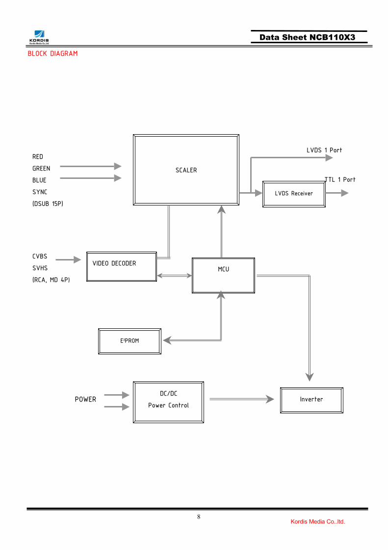
BLOCK DIAGRAM
RED
GREEN
BLUE
SYNC
(DSUB 15P)
SCALER
MCU
E2PROM
Inverter DC/DC
Power Control POWER
CVBS
SVHS
(RCA, MD 4P)
VIDEO DECODER
LVDS 1 Port
TTL 1 Port
LVDS Receiver

9 Kordis Media Co.,ltd.
Data Sheet NCB110X3
ASSEMBLY NOTES This controller is designed for monitors and custom display projects using 1024x768, resolution TFT LCD panels with a VGA, SVGA, XGA signal input. The following provides some guidelines for installation and preparation of a finished display solution. Preparation: Before preceding it is important to familiarize yourself with the parts making up the system and the various connectors, mounting holes and general layout of the controller. As much as possible connectors have been labeled. Guides to connectors and mounting holes are shown in the following relevant sections.
1. LCD Panel: This controller has 12V, 5V or 3.3V TTL and LVDS interface logic on the Board for different kind of TFT LCD panel. For the other type of LCD interface like Panel Link interface and etc, this board can accommodate a daughter board instead of on-board LCD interface. Due to the different signal timing and electrical characteristics from each LCD panel manufacturer, for selecting LCD interface type and resolution, put jumper marked J5 on the right position following LCD panel specification. For selecting DC power level, put jumper marked J19 on the right position. Supplied power level depends on LCD panel specification.
2. Controller: Handle the controller with care as static charge may damage electronic components, Make sure correct jumper and switches settings to match the target LCD panel
3. LCD connector board: Different makers and models of LCD panel require different panel signal connectors and different pin assignments.
4. LCD signal cables: In order provide a clean signal it is recommended that LCD signal cables should not longer than 30cm. If loose wire cabling is utilized these can be a made into a harness with cable ties. Care should be taken when you place the cables to avoid signal interface. Additionally it may necessary in some systems to add ferrite cores to the cables to minimize signal noise.
5. Inverter: This will be required for the backlight of an LCD, some LCD panel have an inverter built in. As LCD panels may have 1 or more backlight tubes and the power requirements for different panel backlights may vary it is important to match the inverter in order to obtain optimum performance. See application notes for more information on connection.
6. Inverter cable: Different inverter models require different cables and different pin assignment. Make sure the correct cable pin out to match the inverter. Unsuitable cable pins out may damage the inverter.
7. AV cable: Standard composite or S-video cables can be used. Reasonable quality cables should be used to avoid image quality degradation.
8. OSD Button: See Operational Function section.
9. 3 Color LED: This LED shows the state of controller.
Green – Normal state
Off – Off mode (Can’t find video signals)

10 Kordis Media Co.,ltd.
Data Sheet NCB110X3
Amber – DPMS mode
10. Power switch: This switch is located on OSD button board.
11. Power input: +12Vdc is required to supply power for the controller, the Inverter and the LCD panel
12. VGA Input Cable: As this may affect regulatory emission test result, a suitably shielded cable should be utilized.
EMI: Shielding will be required for passing certain regulatory emissions tests. Also the choice of video board and power supply can affect the test result.
Consideration should be given to:
Electrical insulation.
Grounding.
EMI shielding.
Heat & ventilation
Caution: Ensure that the equated insulation is provided for all areas of the PCB with special attention to high voltage parts such as the inverter.
13. Setup for operation
Once the circuit has been connected, a setup procedure for optimal is requires a few minutes The following instructions are likely to form the basis of the finished product operation manual.
PC Settings
The PC needs to be set to an appropriate graphics mode that has the same resolution with the LCD panel to have clear screen image. And the vertical refresh rate should be set to one of 56~75Hz, non – interlaced signal. LCD display System Settings The OSD (On Screen Display) provides certain functions to have clear image and others. This board supports 4 buttons OSD operation as a standard, but 6 - button operation can be supported with a different firmware if it is required. The control functions defined on OSD operation are as below. Pc Graphics Output: A few guidelines:
Signal quality is very important, if there is noise or instability in the PC graphics output this may result in visible noise on the display Refer to the graphic modes table in specification section for supported modes. Non-interlaced & interlaced video input is acceptable.
Important: please read the application notes section for more information.

11 Kordis Media Co.,ltd.
Data Sheet NCB110X3
CONNECTION & OPERATION CAUTION: Never connect or disconnect parts of the display system when the system is powered up as this
may cause serious damage. CONNECTION 1. LCD panel & inverter: Connect the inverter (if it is not built- in the panel) to the CCFT lead
connector of the LCD panel. 2. TTL type panels: Plug the signal cables direct to J14 (for Single 6bits, or Single (Dual first) higher
6bit, J13 (8bit dual (J13) and 8bits single lower 2bit) on the controller board. Plug the other end of cables to the LCD connector board (if connector board is required, otherwise the signal can be directly plugged to the LCD panel connector). LVDS type panels: Plug the signal cables direct to J100 of the controller board. Plug the other end of cables to the LCD connector board (if connector board is required, otherwise the signal can be directly plugged to the LCD panel connector).
3. Inverter & Controller: Plug the inverter cable to J8 of the controller board and another end to the connector on the inverter.
4. Function switch & Controller: Plug the OSD switch mount cable to J2 of the controller board and another end to the OSD board.
5. Jumpers & Switch: Check all jumpers {J19 (External power Setting), J17 (Target panel power is setting)} and switches (J14, Target panel selection) are set correctly. Details referring the jumpers and switches setting table (in the following section)
6. VGA cable & Controller: Plug the VGA cable to the connector J3 of the controller board. 7. Power supply & Controller: Plug the DC 12V power in to the connector J7. 8. Power on: Switch on the controller board and panel by using the OSD switch mount.
General: If you use supplied cables & accessories, ensure that they are correct for the model of the panel
and the controller. If you make your own cables & connectors, refer carefully to both the panel & inverter
specifications and the section in this manual, “Connectors, Pin outs & Jumpers” to ensure the correct pin to pin wiring.
PC Setting: The controller has been designed to take a very wide range of input signals however to optimize the
PC’s graphic performance we recommend choosing 60Hz vertical refresh rate – this will not cause screen flicker.

12 Kordis Media Co.,ltd.
Data Sheet NCB110X3
OSD The OSD (On Screen Display) provides certain functions to have clear image and others. This board supports 4 buttons OSD operation as a standard. The control functions defined on OSD operation are as below. (unit: mm)
Button Function Status HOT Key
Power Power on/off On/Off
Menu Activate menu
Select Menu Select Auto setting
LED Indicates operation status Green/ Off/ Amber
DOWN, UP Cursor control Increment / Decrement value
Source change
The chosen OSD settings will be stored in memory. The OSD menu can be cleared from the screen from the screen by moving the selection bar to the EXIT MENU icon pressing the SEL button otherwise it will be automatically cleared after a few second of non-use
UPDOWN
POWER
ON/OFF LEDMEN
SEL
AUTO
8.5
1.6 3
Source change

13 Kordis Media Co.,ltd.
Data Sheet NCB110X3
OSD Function (MAIN MENU) Picture
In case of AV (Video & S-Video ) mode In case of PC mode
Setup
Screen

14 Kordis Media Co.,ltd.
Data Sheet NCB110X3
Picture Icon
PSM (AV)
CSM (PC)

15 Kordis Media Co.,ltd.
Data Sheet NCB110X3
Brightness / Contrast / Color / Sharpness
Tint
Setup

16 Kordis Media Co.,ltd.
Data Sheet NCB110X3
Language
Transparency
Factory Reset

17 Kordis Media Co.,ltd.
Data Sheet NCB110X3
Screen
Auto Configure
H Position / V Position / Clock / Phase

18 Kordis Media Co.,ltd.
Data Sheet NCB110X3
OSD GUI Control Table MAIN MENU SUB MENU CONTROL
Dynamic/Standard/Mild/Game/User PSM
USER Brightness, Contrast, Color, Sharpness VIDEO
CSM/Brightness/Contrast
CSM Normal/Warm/User
PICTURE
CSM
User Red/Green/Blue
PC
Language English/Deutsch/François/Italiano/Espanol
Transparency 50 (1 ~100) SETUP
Factory Reset On/Off
Auto Configure On/Off
H Position 50( 0 ~ 100)
V Position 50( 0 ~ 100)
Clock 50( 0 ~ 100)
SCREEN
Phase 50( 0 ~ 100)
RGB PC

19 Kordis Media Co.,ltd.
Data Sheet NCB110X3
Operation Message
OUT OF FREQUENCY Input Signal is over the supporting range
POWER SAVER MODE Input Signal is not present. This message isdisappeared after 5 seconds.
SELF DIAGNOSTICS Input Signal is not present after power on with power switch. This message is not disappeared before power off or activity of input signal.
AUTO CONFIGURATION Execute AUTO Function.
20 Kordis Media Co.,ltd.
Data Sheet NCB110X3
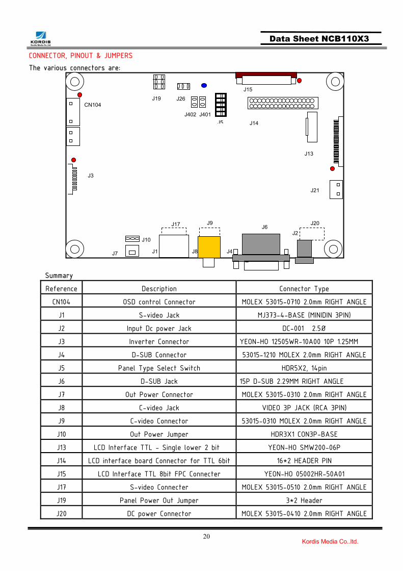
CONNECTOR, PINOUT & JUMPERS The various connectors are: Summary
Reference Description Connector Type
CN104 OSD control Connector MOLEX 53015-0710 2.0mm RIGHT ANGLE
J1 S-video Jack MJ373-4-BASE (MINIDIN 3PIN)
J2 Input Dc power Jack DC-001 2.5Ø
J3 Inverter Connector YEON-HO 12505WR-10A00 10P 1.25MM
J4 D-SUB Connector 53015-1210 MOLEX 2.0mm RIGHT ANGLE
J5 Panel Type Select Switch HDR5X2, 14pin
J6 D-SUB Jack 15P D-SUB 2.29MM RIGHT ANGLE
J7 Out Power Connector MOLEX 53015-0310 2.0mm RIGHT ANGLE
J8 C-video Jack VIDEO 3P JACK (RCA 3PIN)
J9 C-video Connector 53015-0310 MOLEX 2.0mm RIGHT ANGLE
J10 Out Power Jumper HDR3X1 CON3P-BASE
J13 LCD Interface TTL - Single lower 2 bit YEON-HO SMW200-06P
J14 LCD interface board Connector for TTL 6bit 16*2 HEADER PIN
J15 LCD Interface TTL 8bit FPC Connecter YEON-HO 05002HR-50A01
J17 S-video Connecter MOLEX 53015-0510 2.0mm RIGHT ANGLE
J19 Panel Power Out Jumper 3*2 Header
J20 DC power Connector MOLEX 53015-0410 2.0mm RIGHT ANGLE
J7
J6J2
J14
J3
CN104
J5
J19
J10
J1 J8
J26
J13
J21
J20
J4
J9J17
J15
J401J402

21 Kordis Media Co.,ltd.
Data Sheet NCB110X3
J401 F/W Jumper Setting (Optional) 2*2 Header
J402 F/W Jumper Setting (Optional) 2*2 Header
CN104 : OSD control connector
Pin No. Symbol Description
1 VCC +5V power for IR sensor
2 IRQ Infrared rays signal line.
3 LED2 RED LED
4 LED1 GREEN LED
5 GND Ground
6 KEY1 Up, Power
7 KEY0 Menu, Select, Down
J1: S-Video Input Jack
Pin No. Symbol Description
1 GND Ground
2 GND Ground
3 C-in CROMA signal input
4 Y-in LUMA signal input
5 GND Ground
6 GND Ground
7 GND Ground
J2: 12V DC power supply
Pin No. Symbol Description1 Vcc 12V2 GND Ground3 GND Ground
J3: Backlight Inverter connector
Pin No. Symbol Description Pin No. Symbol Description
1 DIM-adj DIM-adjustment 6 GND Ground
2 GND Ground 7 GND Ground
3 GND Ground 8 GND Ground
4 GND Ground 9 Vcc 12V
5 ON/OFF Inverter ON/OFF 10 Vcc 12V

22 Kordis Media Co.,ltd.
Data Sheet NCB110X3
J4: Analog RGB Input Connector
Pin No. Symbol Description
1 SCL Serial Clock Line for DDC
2 SDA Serial Data Line for DDC
3 NC No Connection
4 VSYNC Vertical Sync
5 HSYNC Horizontal Sync
6 GND Ground for HSYNC, VSNC, SCL, SDA
7 BLUE BLUE analog input
8 BLUE GND Ground for BLUE Input Signal
9 GREEN GREEN analog input
10 GREEN GND Ground for GREEN Input Signal
11 RED RED analog input
12 RED GND Ground for RED Input Signal
J5: Panel Type Select Switch * Refer to Appendix for setting J6 : ANALOG VGA INPUT
Pin No. Symbol Description
1 Red1 Red analog input
2 Green1 Green analog input
3 Blue1 Blue analog input
4 GND Ground
5 GND Ground
6 GND Ground
7 GND Ground
8 GND Ground
9 NC Not connected
10 GND Ground
11 GND Ground
12 DSDA DDC-SDA
13 HSYNC Horizontal Sync
14 VSYNC Vertical Sync
15 DSCL Serial Clock Input
23 Kordis Media Co.,ltd.
Data Sheet NCB110X3
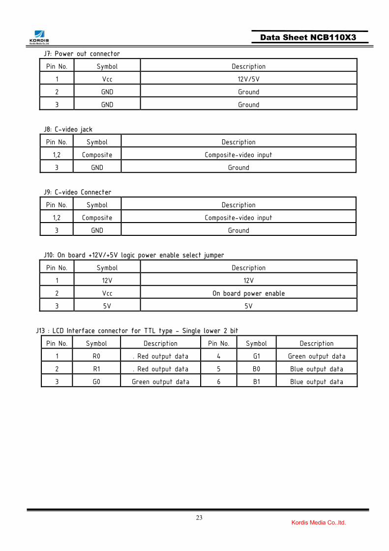
J7: Power out connector
Pin No. Symbol Description
1 Vcc 12V/5V
2 GND Ground
3 GND Ground
J8: C-video jack
Pin No. Symbol Description
1,2 Composite Composite-video input
3 GND Ground
J9: C-video Connecter
Pin No. Symbol Description
1,2 Composite Composite-video input
3 GND Ground
J10: On board +12V/+5V logic power enable select jumper
Pin No. Symbol Description
1 12V 12V
2 Vcc On board power enable
3 5V 5V
J13 : LCD Interface connector for TTL type - Single lower 2 bit
Pin No. Symbol Description Pin No. Symbol Description
1 R0 . Red output data 4 G1 Green output data
2 R1 . Red output data 5 B0 Blue output data
3 G0 Green output data 6 B1 Blue output data

24 Kordis Media Co.,ltd.
Data Sheet NCB110X3
J14: LCD Interface connector for TTL type- 6bit For Single 6bits, or Single (Dual first) higher 6bit
Pin No. Symbol Description
1 ROA (7) Red output data
2 ROA (6) Red output data
3 ROA (5) Red output data
4 ROA (4) Red output data
5 ROA (3) Red output data
6 ROA (2) Red output data
7 GND Ground
8 GND Ground
9 GOA (7) Green output data
10 GOA (6) Green output data
11 GOA (5) Green output data
12 GOA (4) Green output data
13 GOA (3) Green output data
14 GOA (2) Green output data
15 GND Ground
16 GND Ground
17 BOA (7) Blue output data
18 BOA (6) Blue output data
19 BOA (5) Blue output data
20 BOA (4) Blue output data
21 BOA (3) Blue output data
22 BOA (2) Blue output data
23 GND Ground
24 GND Ground
25 DVS Display Vertical Sync
26 DHS Display Horizontal Sync
27 DCLK Display Clock
28 GND Ground
29 DEN Display Enable
30 MOD_PWR VDD For LCD Module
31 MOD_PWR VDD For LCD Module
32 MOD_PWR VDD For LCD Module

25 Kordis Media Co.,ltd.
Data Sheet NCB110X3
J15: LCD Interface connector for 8bit TTL type
Pin No. Symbol Description Pin No. Symbol Description
1 NC . 26 R1 Red output data
2 NC . 27 R2 Red output data
3 GND Ground 28 R3 Red output data
4 GND Ground 29 GND Ground
5 B0 Blue output data 30 R4 Red output data
6 B1 Blue output data 31 R5 Red output data
7 B2 Blue output data 32 R6 Red output data
8 B3 Blue output data 33 R7 Red output data
9 GND Ground 34 GND Ground
10 B4 Blue output data 35 CLK Display Clock
11 B5 Blue output data 36 GND Ground
12 B6 Blue output data 37 DE Display Enable
13 B7 Blue output data 38 GND Ground
14 GND Ground 39 VSYNC Display Vertical Sync
15 G0 Green output data 40 HSYNC Display Horizontal Sync
16 G1 Green output data 41 GND Ground
17 G2 Green output data 42 VCC VDD For LCD Module
18 G3 Green output data 43 VCC VDD For LCD Module
19 GND Ground 44 VCC VDD For LCD Module
20 G4 Green output data 45 VCC VDD For LCD Module
21 G5 Green output data 46 GND Ground
22 G6 Green output data 47 GND Ground
23 G7 Green output data 48 NC .
24 GND Ground 49 NC .
25 R0 Red output data 50 NC .
* Optional connector for LC201V01 (LG) & A201SN01/2 (AU)
26 Kordis Media Co.,ltd.
Data Sheet NCB110X3
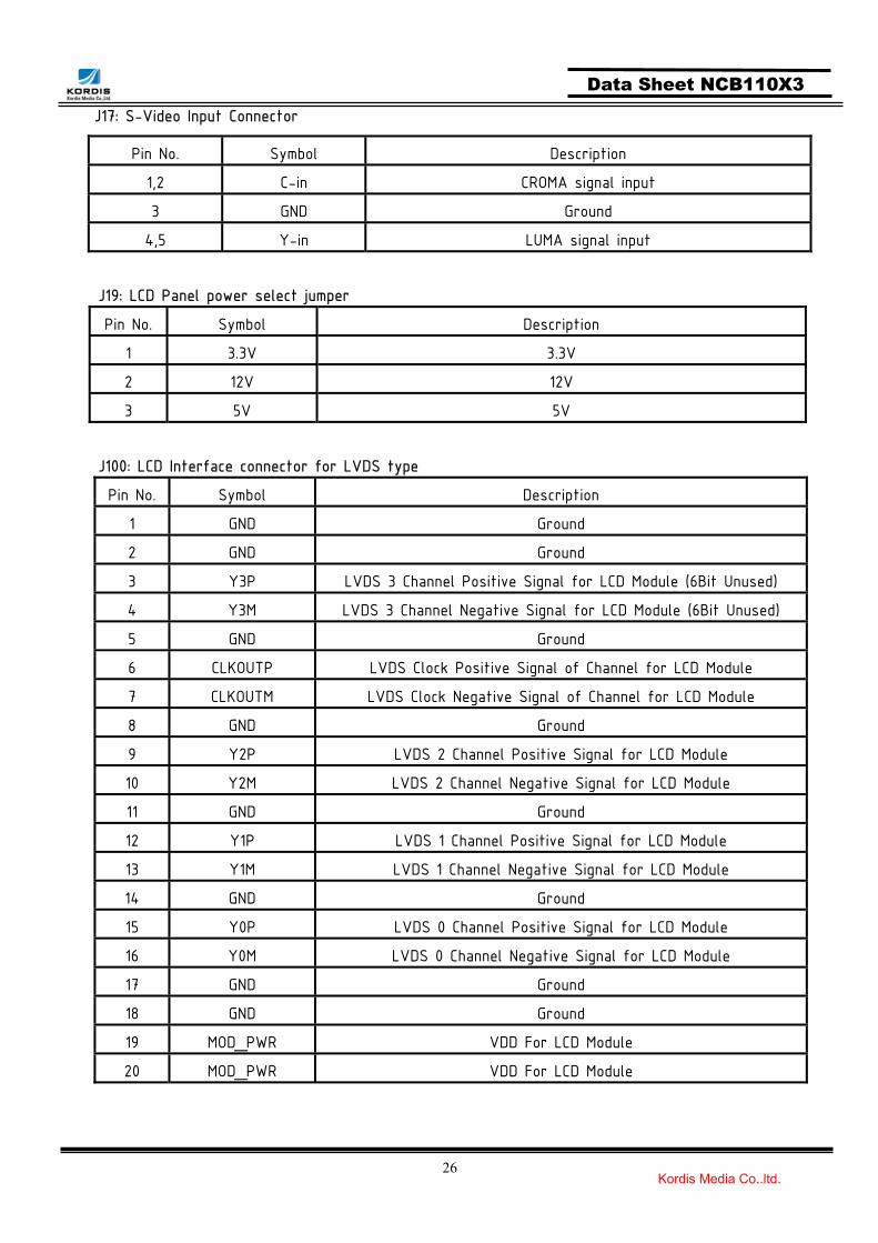
J17: S-Video Input Connector
Pin No. Symbol Description
1,2 C-in CROMA signal input
3 GND Ground
4,5 Y-in LUMA signal input
J19: LCD Panel power select jumper
Pin No. Symbol Description
1 3.3V 3.3V
2 12V 12V
3 5V 5V
J100: LCD Interface connector for LVDS type
Pin No. Symbol Description
1 GND Ground
2 GND Ground
3 Y3P LVDS 3 Channel Positive Signal for LCD Module (6Bit Unused)
4 Y3M LVDS 3 Channel Negative Signal for LCD Module (6Bit Unused)
5 GND Ground
6 CLKOUTP LVDS Clock Positive Signal of Channel for LCD Module
7 CLKOUTM LVDS Clock Negative Signal of Channel for LCD Module
8 GND Ground
9 Y2P LVDS 2 Channel Positive Signal for LCD Module
10 Y2M LVDS 2 Channel Negative Signal for LCD Module
11 GND Ground
12 Y1P LVDS 1 Channel Positive Signal for LCD Module
13 Y1M LVDS 1 Channel Negative Signal for LCD Module
14 GND Ground
15 Y0P LVDS 0 Channel Positive Signal for LCD Module
16 Y0M LVDS 0 Channel Negative Signal for LCD Module
17 GND Ground
18 GND Ground
19 MOD_PWR VDD For LCD Module
20 MOD_PWR VDD For LCD Module

27 Kordis Media Co.,ltd.
Data Sheet NCB110X3
Summary: jumpers setting
Reference Description Connector Type
On board +12V logic power enable
J10
On board +5V logic power enable
12V panel power CAUTION: Incorrect setting can
damage panel
5V panel power CAUTION: Incorrect setting can
damage panel
J19
3.3V panel power CAUTION: Incorrect setting can
damage panel
5V 12V
5V 12V
3.3V
12V
5V
3.3V
12V
5V
3.3V
12V
5V

28 Kordis Media Co.,ltd.
Data Sheet NCB110X3
Inverter Dimming Setting 0V
(For Monitor LCD)
J26
Inverter Dimming Setting 3.3V (For LCD TV)
Composite Video only Setting
J401
Normal F/W Setting
DIMADJ2 DIMADJ1
DIMADJ2 DIMADJ1

29 Kordis Media Co.,ltd.
Data Sheet NCB110X3
CONTROLLER DIMENSIONS
1.6T 14.64mm
Max 3mm
145
105

30 Kordis Media Co.,ltd.
Data Sheet NCB110X3
APPLICATION NOTES USING THE CONTROLLER WITHOUT BOTTONS ATTACHED This is very straightforward:
Firstly setup the controller/display system with the buttons. With the attached controllers and display system active make any settings for color, contrast and image position as required then switch everything off. Remove the control switches, the 7-way (J2) cable. Refer to inverter specifications for details as to fixing brightness to a desired level, this may
require a resistor, an open circuit or closed circuit depending on inverter INVERTER CONNECTION There are 3 potential issues to consider with inverter connection:
Power ON/OFF Brightness (DIM-ADJ)
Inverter power: This should be matched with the inverter specification. Inverter ON/OFF: This is a pin provided on some inverter for ON/OFF function and is used by this panel controller for VESA DPMS compliance. If the inverter does not have on/off pin or the on/off pin is not used DPMS will not operate. Pin 5 should be matched to the inverter specification for the ON/OFF pin. Brightness Dimming control: NCB110 controller boards are analog dimming control method. And it is important to consider the specifications for the inverter to be used.

31 Kordis Media Co.,ltd.
Data Sheet NCB110X3
TROUBLESHOOTING General A general guide to troubleshooting of a flat panel display system it worth considering the system as separate elements, such as: ► Controller (jumpers, PC settings) ► Panel (controller, cabling, connection, panel, PC settings) ► Backlight (inverter, cabling, connection, panel, Pc settings) ► Cabling ► Computer system (display settings, operating system) Through checking the system step by step cross with instruction manuals and a process of elimination to isolate the problem it is usually possible to clearly identify the problem area. No image: ► If the panel backlight is not working it may still be possible to see just some image. ► A lack of image is most likely to be caused by incorrect connection, lack of power, failure to provide a
signal or incorrect graphic card settings. Image position: If it is impossible to position the image correctly, ie the image adjustment controls will not move the image far enough, then test using another graphics card. This situation can occur when a graphic card is not close to standard timing or when something is in the graphics line that may affect the signal such as a signal splitter (please note that normally a signal splitter will not have any adverse effect). Image appearance: ► A faulty panel can have blank lines, failed sections, flickering or flashing display. ► Incorrect graphic card refresh rate, resolution or interlaced mode will probably cause the image to be
the wrong size, to scroll to, flicker badly or possibly even no image. ► Incorrect jumper settings on the controller may cause everything from incorrect image viewing to total failure. CAUTION: Do not set the panel power input incorrectly. ► Sparkling on the display: faulty panel signal cable. Backlight: Items to check include: Power input, controls, inverter and Tubes generally in this order. If half the screen is dimmer than the other half: ► Check cabling for the inverter. Also: ► If system does not power down when there is a loss of signal.

32 Kordis Media Co.,ltd.
Data Sheet NCB110X3
APPLICABLE GRAPHIC MODE The microprocessor measures the, H – sync V – sync and polarity for RGB Inputs, and uses this timing information to control all of the display operation to get the proper image on a screen. This board can detect all VESA standard Graphic modes shown on the table below and Provide mare clear and stable image on a screen
Table 6.1) RGB input format
Horizontal Timing Vertical Timing Pixel Freq. Freq. Total Active Freq. Total Active
Spec
Mode MHz
SyncPolar KHz Pixel Pixel
SyncPolar Hz Line Lind
640*350@70Hz 25.144 P 31.430 800 640 N 70.000 449 350
640*400@70Hz 28.287 N 31.430 800 640 P 70.000 449 400
720*400@ 70Hz 28.287 N 31.430 900 720 P 70.000 449 400
640*480@60Hz 28.175 N 31.469 800 640 N 59.940 525 480
640*480@72Hz 31.500 N 37.861 832 640 N 72.809 520 480
640*480@75Hz 31.500 N 37.500 840 640 N 75.000 500 480
800*600@56 Hz 36.000 P 35.156 1024 800 P 56.250 625 600
800*600@60Hz 40.000 P 37.879 1056 800 P 60.317 628 600
800*600@72Hz 50.000 P 48.077 1040 800 P 72.188 666 600
800*600@75Hz 49.500 P 46.875 1056 800 P 75.000 625 600
1024*768@60Hz 65.000 N 48.363 1344 1024 N 60.005 806 768
1024*768@ 70Hz 75.000 N 56.476 1328 1024 P 70.070 806 768
1024*768@75Hz 78.750 P 60.023 1312 1024 P 75.030 800 768
ACCESSORY This board requires several accessories to build a complete display unit. KORDIS can provide standard accessory for this board as below.
No. Items Part No. Ex) LG. Philips LB064V2
1 LCD signal cable SC-Panel Part No.-mm SC-LB064V2-20
2 Inverter Part no. of Manufacturer GH006
3 Inverter cable IC-Panel Part No.-mm IC-GH006-20
4 OSD Board NLX05-OSD NLX05-OSD
5 OSD Cable OC-NID01-mm OC-NID01-20
* SC: LCD Signal Cable IC: Inverter Interface cable OC: OSD Board cable mm: Cable length(unit: mm)

33 Kordis Media Co.,ltd.
Data Sheet NCB110X3
APPENDIX * 1 ~ 2 : Output Resolution
* 3 : LVDS MAP ON : LVDS MAP2 (Shift) OFF :LVDS MAP1 (Normal)
* 4 : Panel 6bit or 8bit ON: 6bit OFF : 8bit
* 5 : LVDS Channel Selection ( * ) ON : Normal Panel OFF: SHARP / Hydis Panel (VGA / SVGA: Sharp)
1 2 Resolution
ON ON 640x480
ON OFF 800x600
OFF ON 1024x760
OFF OFF *
RCLK
NC B1 B0 G1 G0 R1 R0RD
DE VS HS B7 B6 B5 B4RC
B3 B2 G7 G6 G5 G4 G3RB
G2 R7 R6 R5 R4 R3 R2RA
LVDS MAP2
RCLK
NC B7 B6 G7 G6 R7 R6RD
DE VS HS B5 B4 B3 B2RC
B1 B0 G5 G4 G3 G2 G1RB
G0 R5 R4 R3 R2 R1 R0RA
LVDS MAP1
< Normal >
< Shift >
34 Kordis Media Co.,ltd.
Data Sheet NCB110X3
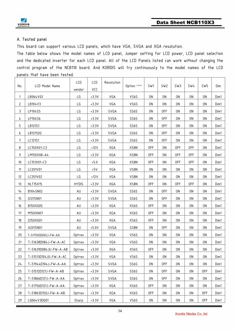
A. Tested panel This board can support various LCD panels, which have VGA, SVGA and XGA resolution. The table below shows the model names of LCD panel, Jumper setting for LCD power, LCD panel selection and the dedicated inverter for each LCD panel. All of the LCD Panels listed can work without changing the control program of the NCB110 board. And KORDIS will try continuously to the model names of the LCD panels that have been tested.
No. LCD Model Name LCD
vendor
LCD
VCC
ResolutionOption (note1) SW1 SW2 SW3 SW4 SW5 Dim
1 LB064V02 LG +3.3V VGA VS6S ON ON ON ON ON Dim1
2 LB104V3 LG +3.3V VGA VS6S ON ON ON ON ON Dim1
3 LP104S5 LG +3.3V SVGA SS6S ON OFF ON ON ON Dim1
4 LP104S6 LG +3.3V SVGA SS6S ON OFF ON ON ON Dim1
5 LB121S1 LG +3.3V SVGA SS6S ON OFF ON ON ON Dim1
6 LB121S02 LG +3.3V SVGA SS6S ON OFF ON ON ON Dim1
7 LC121S1 LG +3.3V SVGA SS6S ON OFF ON ON ON Dim1
8 LC150X01-C3 LG +12V XGA XS8N OFF ON OFF OFF ON Dim1
9 LM150X08-A4 LG +3.3V XGA XS8N OFF ON OFF OFF ON Dim1
10 LC151X01-C3 LG +5.0 XGA XS8N OFF ON OFF OFF ON Dim1
11 LC201V01 LG +5V VGA VS8N ON ON ON ON ON Dim1
12 LC201V02 LG +12V VGA VS8N ON ON ON ON ON Dim1
13 HLT15X15 HYDIS +3.3V XGA XS8N OFF ON OFF OFF ON Dim1
14 B104SN02 AU +3.3V SVGA SS6S ON OFF ON ON ON Dim1
15 G121SN01 AU +3.3V SVGA SS6S ON OFF ON ON ON Dim1
16 B150XG05 AU +3.3V XGA XS6S OFF ON ON ON ON Dim1
17 M150XN07 AU +3.3V XGA XS6S OFF ON ON ON ON Dim1
18 G150XG01 AU +3.3V XGA XS6S OFF ON ON ON ON Dim1
19 A201SN01 AU +5.0V SVGA SS8N ON OFF ON ON ON Dim1
20 T-51750GD065J-FW-AA Optrex +3.3V VGA VS6S ON ON ON ON ON Dim1
21 T-51638D084J-FW-A-AC Optrex +3.3V VGA VS6S ON ON ON ON ON Dim1
22 T-51639D084JU-FW-A-AB Optrex +3.3V XGA XS6S OFF ON ON ON ON Dim1
23 T-51513D104JU-FW-A-AC Optrex +3.3V VGA VS6S ON ON ON ON ON Dim1
24 T-51944D104J-FW-A-AA Optrex +3.3V SVGA SS6S ON OFF ON ON ON Dim1
25 T-51512D121J-FW-A-AB Optrex +3.3V SVGA SS6S ON OFF ON ON OFF Dim1
26 T-51866D121J-FW-A-AA Optrex +3.3V SVGA SS6S ON OFF ON ON ON Dim1
27 T-51756D121J-FW-A-AA Optrex +3.3V XGA XS6S OFF ON ON ON ON Dim1
28 T-51863D150J-FW-A-AB Optrex +3.3V XGA XS6S OFF ON ON ON OFF Dim1
29 LQ064V3DG01 Sharp +3.3V VGA VS6S ON ON ON ON OFF Dim1

35 Kordis Media Co.,ltd.
Data Sheet NCB110X3
30 LQ104V1DG51 Sharp +3.3V VGA VS6S ON ON ON ON OFF Dim1
31 LQ104S1DG21 Sharp +3.3V SVGA SS6S ON OFF ON ON OFF Dim1
32 LQ121S1DG41 Sharp +3.3V SVGA SS6S ON OFF ON ON OFF Dim1
33 NL10276BC12-02 NEC +3.3V XGA XS6N OFF ON ON ON ON Dim1
34 LQ084S3DG01 Sharp +3.3V VGA VS6S ON ON ON ON ON Dim1
Note1 : Abbreviated word : SⓐSⓑ6ⓒSⓓ
ⓐ V/S/X : V VGA, S SVGA, X XGA ⓑ S/D : SINGLE PORT, D DUAL PORT
ⓒ 6/8 : 6 6BITS 8 8BITS ⓓ S/N : (SFT) SHIFT, N(NOR) NORMAL