Embed Size (px)
Citation preview
0603cidephoto1
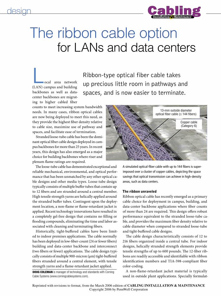
13-mm outside diameteroptical fiber cable (≤ 144 fibers)
Copper cable(Category 6)
design
Local area network (LAN) campus and building backbones as well as data-center backbones are migrat-ing to higher cabled fiber counts to meet increasing system bandwidth needs. In many cases, ribbon optical cables are now being deployed to meet this need, as they provide the highest fiber density relative to cable size, maximize use of pathway and spaces, and facilitate ease of termination.
Stranded loose-tube cable has been the domi-nant optical fiber cable design deployed in cam-pus backbones for more than 25 years. In recent years, this design has also emerged as a major choice for building backbones where riser and plenum flame ratings are required.
The loose-tube cable has demonstrated exceptional and reliable mechanical, environmental, and optical perfor-mance that has been unmatched by any other optical ca-ble designs and other media types. Loose-tube design typically consists of multiple buffer tubes that contain up to 12 fibers and are stranded around a central member. High tensile strength yarns are helically applied around the stranded buffer tubes. Contingent upon the deploy-ment location, a non-flame or flame-retardant jacket is applied. Recent technology innovations have resulted in a completely gel-free design that contains no filling or flooding compounds, eliminating the time and labor as-sociated with cleaning and terminating fibers.
Historically, tight-buffered cables have been limit-ed to indoor premises applications. The cable normally has been deployed in low-fiber-count (24 or fewer fibers) building and data-center backbone and interconnect (two fibers or fewer) applications. The cable design typi-cally consists of multiple 900-micron (µm) tight-buffered fibers stranded around a central element, with tensile strength yarns and a flame-retardant jacket applied.
The ribbon unraveledRibbon optical cable has recently emerged as a primary cable choice for deployment in campus, building, and data-center backbone applications where fiber counts of more than 24 are required. This design offers robust performance equivalent to the stranded loose-tube ca-ble, and provides the maximum fiber density relative to cable diameter when compared to stranded loose-tube and tight-buffered cable designs.
The cable design characteristically consists of 12 to 216 fibers organized inside a central tube. For indoor designs, helically stranded strength elements provide tensile strengths of up to 600 pounds. The 12-fiber rib-bons are readily accessible and identifiable with ribbon identification numbers and TIA-598-compliant fiber color-coding.
A non-flame-retardant jacket material is typically used in outside plant applications. Specially formulat-
A simulated optical-fiber cable with up to 144 fibers is super-imposed over a cluster of copper cables, depicting the space savings that optical transmission can achieve in high-density areas, such as data centers.
The ribbon cable option for LANs and data centers
Ribbon-type optical fiber cable takes up precious little room in pathways and spaces, and is now easier to terminate.
DOUG COLEMAN is manager of technology and standards with Corning Cable Systems (www.corningcablesystems.com).
Reprinted with revisions to format, from the March 2006 edition of CABLING INSTALLLATION & MAINTENANCECopyright 2006 by PennWell Corporation

0603cidef1
PE outer jacket
Ripcord
Dielectricstrength members
(as required)
Water-swellable tape
Filled buffer tube FibersWater-swellable yarn
Dielectriccentral
member
All drawings courtesy ofCorning Cable Systems
Loose-tube cable
0603cidef2
PVC outer jacket
Ripcord
Dielectricstrength members
900-µm TBII buffered fibers
Dielectriccentral
members
Tight-buffered cable
0603cidef3
UV-resistantflame-retardant
outer jacket
Ripcords
Filled buffer tube
Optical fiberribbons
Dielectric strength members
Water-swellable tape
12-fiber ribbon cable
Dielectricstrength members
0603cidef4
12-fiber ribbon
Boot
Coupling/housingassembly
MTP connector
Ferrule
Guide pins(2)
Dust cap
ed flame-retardant outer jackets are used for indoor appli-cations so that the cable design meets the requirements of the NFPA-262 flame test for ribbon plenum cables, as well as the requirements of the UL-1666 flame test for ribbon riser cables. Like the stranded loose-tube cable, completely gel-free designs are available.
For many years, design-ers and installers have been reluctant to specify ribbon optical cable in the LAN and data center because 12-fiber ribbon field terminations were limited. But with the introduction of inno-vations such as ribbon-splitting tools, ribbon-furcation kits, and field-installable 12-fiber array connectors, 12-fiber ribbons can be easily terminated with simplex and duplex connectors (such as LC or SC type) or with the MTP array connector.
The MTP connector is a 12-fiber push/pull optical connec-tor with a footprint similar to the SC simplex connector. These
high-density connectors are used to significantly accelerate the network cabling process, minimize errors, and reduce congestion in patch panels.
The MTP connector is commonly available in pretermi-nated form—as a pigtail to be spliced onto a 12-fiber rib-bon, or as an MTP connector backbone assembly that is terminated on each end. Field-installable MTP con-nectors are also available with a no-epoxy, no-polish de-sign that lets you terminate 12 fibers in less than five minutes. The MTP connector is specified to conform to the TIA/EIA-604-5 intermateability standard.
Many end-users are now using factory-terminated cables with MTP and/or simplex or duplex connectors to ensure the
A 12-fiber ribbon cable can be used in outside plant applications, or inside buildings when covered with flame-retardant outer jackets.
Tight-buffered cables are typically deployed in backbones containing 24 or fewer fibers, and interconnects with one or two fibers.
The MTP array connector houses 12 fibers in a footprint similar to that of the single-fiber SC connector.
With the introduction of innovations such as ribbon-splitting tools,
ribbon-furcation kits, and field-installable 12-fiber array connectors,
12-fiber ribbons can be easily terminated with simplex and duplex
connectors or with the MTP array connector.
The gel-free loose-tube cable, without filling or flooding compounds, eliminates time and labor associated with cleaning and termination.

0603cidef5
MTP harness assembly
0603cidef6
LC duplexconnector
MTPconnectors
MTP connector module
highest quality connector insertion-loss and return-loss per-formance, as well as to expedite cable installation. This is espe-cially true in the data-center environment where short-cycle installations and limited time availability for moves, adds, and changes make simplified and fast installations critical.
MTP connectorized ribbon cable typically is terminated in patch panels using one of two methods:• Method 1 is normally used in an interconnect application
where a harness assembly is used on the front of the patch panel. Harness assemblies are used to break out the 12-fi-ber MTP connectors termi-nated on ribbon cables into simplex- or duplex-style con-nectors. Harness assemblies have MTP connectors on one end of the cable while the other end is equipped with simplex or duplex style connectors. The harness as-sembly interconnects with the backbone ribbon cable at the patch panel MTP connector adapter.
• Method 2 is used in both interconnect and cross-connect ap-plications where an MTP connector module is used. MTP connector modules are used to break out the 12-fiber MTP connectors terminated on a ribbon cable into simplex or duplex style connectors. Simplex and duplex style jumper patch cords then can be used to patch into system equipment ports, patch panels, or client outlets. The module features simplex or duplex port adapters across the front and one or two MTP connector adapters across the back. Fiber polari-ty is maintained with an integrated wiring scheme built in-to the module that ensures proper transmitter-to-receiver
continuity throughout the system; so, when end equipment patch cords are installed, transmit goes to receive.
Pathway and spacesIt is critical to maximize use of pathway and spaces, espe-cially in campus and data-center backbones where space is a premium. Ribbon cables offer up to 45 percent space savings,
and three times the fiber-tray capacity over traditional bulk-ier cable solutions while minimizing cable tray weight. Op-timal cabled fiber density in data-center pathway and spaces is important to facilitate efficient cooling systems as well as for removal of abandoned cable in accordance with the Na-tional Electrical Code.
In summary, ribbon optical cable is now being deployed in areas where stranded loose-tube and tight-buffered cable have historically been used. Ribbon cable offers the highest fiber pack-ing density to maximize pathway and space utilization in ducts, raceways, and patch panels. Preterminated or field-terminated ribbon cable is now easily obtained using traditional simplex or duplex connectors, as well as the MTP array connectors.
The MTP connector harness, which breaks the 12-fiber MTP connector into simplex or duplex connectors, is used predominantly in intercon-nect applications.
Used in cross-connect or interconnect applications, this module features simplex or duplex port adapters across the front and one or two MTP connector adapters across the back.
[Ribbon] design offers robust performance equivalent to
the stranded loose-tube cable, and provides the maximum
fiber density relative to cable diameter when compared to
stranded loose-tube and tight-buffered cable designs.
Corning Cable SystemsPO Box 489Hickory, NC 28603-0489Tel: 1.800.743.2675Int’l: +1.828.901.5000Fax: +1.828.902.5973www.corning.com/cablesystems
LAN-736-EN