Embed Size (px)
Citation preview

VERTICAL RIB ROOF INSTALLATION INSTRUCTIONS
LAST REVISIONBY: EGB CHK: KMC
DETAIL NAME IF APPLICABLEPart Number H9925 PAGE 1
FOR FIELD USEPLEASE DISTRIBUTE TO THE ERECTION CREW
DUE TO THE PROCESS OF CONTINUOUS IMPROVEMENT, THE PRODUCTS AND PROCEDURES IN THIS MANUAL ARE SUBJECT TO CHANGE WITHOUT NOTICE
ERECTION MANUAL REVISION INFORMATIONRELEASE TYPE PROJECT NAME PAGES REVISED RELEASE DATE
VR16 II NAME CHANGE 1,25,58,68,& 93 08/06/2019Project Release
28, 30, 39, 40, 41, 43, 44, 46 10/09/201845 08/06/201830 06/18/2018
MaintenanceReleasePages
31,73 04/10/2018
WATERLOO, IN305 Industrial Parkway
Waterloo, IN 46793Phone: 260-837-7891
Fax: 260-837-7384
SWANSEA, SC200 Whetstone RoadSwansea, SC 29160Phone: 803-568-2100
Fax: 803-568-2121
TERRELL, TX600 Apache TrailTerrell, TX 75160
Phone: 972-524-5407Fax: 972-524-5417
BRIGHAM CITY, UT1050 North Watery LaneBrigham City, UT 84302
Phone: 435-919-3100Fax: 435-919-3101
VERTICAL RIB ROOF INSTALLATION INSTRUCTIONS
LAST REVISIONDATE: 07-27-2017BY: EGB CHK: KMC
DETAIL NAME IF APPLICABLEPAGE 2
1.0 GENERAL .............................................................................................................51.1 Purpose of this manual ....................................................................................................51.2 Buyer’s responsibility .......................................................................................................51.3 MBMA ..............................................................................................................................51.4 Disclaimer ........................................................................................................................51.5 Unloading and storing ......................................................................................................61.6 Erection sequence ...........................................................................................................61.7 Coordination with other trades .........................................................................................61.8 Erection care ....................................................................................................................71.9 Field cutting of panels ......................................................................................................71.10 Trim and Flashing ............................................................................................................71.11 Engineering and Reinforcing Materials ............................................................................7
2.0 DESIGN & PERFORMANCE CRITERIA ..............................................................82.1 Roof system .....................................................................................................................82.2 Panel clip spacing ............................................................................................................82.3 Panel clip fastener reqmt’s...............................................................................................82.4 Roof top units and curb supports .....................................................................................82.5 Insulation requirements....................................................................................................8
3.0 COMPOSITE VR16 II ROOF SYSTEM .................................................................93.1 Product definition .............................................................................................................93.2 Vapor barrier ....................................................................................................................93.3 Insulation..........................................................................................................................9
4.0 NUCOR VR16 II ROOF COMPONENTS WITH ENGINEERING ..........................94.1 Components with engineering definition ..........................................................................94.2 Diaphragm........................................................................................................................94.3 Clip fastening requirements .............................................................................................9
5.0 RECEIVING & HANDLING ROOF MATERIALS ................................................105.1 Field storage of materials...............................................................................................105.2 Handling individual roof panels ......................................................................................115.3 Handling roof materials in strong winds .........................................................................115.4 Material inventory...........................................................................................................125.5 Equipment for unloading and lifting................................................................................125.6 Lifting roof panel bundles ...............................................................................................125.7 Placing Panel Bundles on the Roof................................................................................13
6.0 SAFE ROOF INSTALLATION.............................................................................146.1 Regulations ....................................................................................................................146.2 Erector’s responsibility ...................................................................................................146.3 Walking and working on roof panels ..............................................................................146.4 Safety equipment ...........................................................................................................156.5 Crew size .......................................................................................................................156.6 Panel overhang ..............................................................................................................156.7 Point loads .....................................................................................................................156.8 Slick surfaces .................................................................................................................156.9 Electrical conductance ...................................................................................................156.10 False security of insulation.............................................................................................156.11 Sharp edges...................................................................................................................156.12 Safe Roof Installation Summary.....................................................................................16
7.0 CHECKING THE STRUCTURE ..........................................................................177.1 Completed and braced...................................................................................................177.2 Lateral stability ...............................................................................................................177.3 Alignment .......................................................................................................................17

VERTICAL RIB ROOF INSTALLATION INSTRUCTIONS
LAST REVISIONDATE: 07-27-2017BY: EGB CHK: KMC
DETAIL NAME IF APPLICABLEPAGE 3
7.4 Tolerances .....................................................................................................................177.5 Measuring ......................................................................................................................177.6 Aesthetic acceptance .....................................................................................................177.7 Corrections.....................................................................................................................18
8.0 INSTALLATION BASICS....................................................................................188.1 Proper tools....................................................................................................................188.2 Mastic .............................................................................................................................188.3 Fasteners .......................................................................................................................208.4 Field cutting of panels and flashing................................................................................218.5 Sheeting direction and modularity..................................................................................228.6 Layout and checking coverage ......................................................................................228.7 Appearance considerations............................................................................................228.8 Inspection of the roof assembly during installation ........................................................238.9 Inspection list .................................................................................................................238.10 Motorized Panel Seaming & Hand Crimping..................................................................258.11 Roof leak troubleshooting & potential causes of roof leaks ...........................................26
9.0 STANDARD HARDWARE PARTS .....................................................................279.1 General ..........................................................................................................................27
10.0 PREPARATION FOR ROOF PANEL INSTALLATION ......................................3210.1 General ..........................................................................................................................3210.2 Orientation and explanation ...........................................................................................3310.3 Eave plate ......................................................................................................................3410.4 Rake clip pre-drilling detail .............................................................................................3510.5 Insulation........................................................................................................................3610.6 Proper mastic installation procedures ............................................................................3710.7 Understanding Rake Clip and Rake Angle Installation ..................................................3810.8 Rake clip and rake angle installation..............................................................................3910.9 Thermal blocks...............................................................................................................4010.10 EPS foam spacer ...........................................................................................................4010.11 Final pre-panel installation detail....................................................................................41
11.0 EAVE START PANEL INSTALLATION.............................................................4211.1 Panel section, description, and nomenclature ...............................................................4211.2 Installing the eave start panel .......................................................................................4311.3 Installing the leading edge panel clips ...........................................................................4411.4 Typical panel clip attachment details .............................................................................4511.5 Installation of the Lap Stiffener at the eave start panel ..................................................46
12.0 INTERMEDIATE START PANEL INSTALLATION ...........................................4712.1 Installation of intermediate start panel mastic & Caulk ..................................................4712.2 Alignment & Installation of the intermediate start panel .................................................4812.3 Fastening of the intermediate start panel.......................................................................4912.4 Eave Installation.............................................................................................................50
13.0 FULL PANEL RUN INSTALLATION .................................................................5113.1 Installing the first full panel run, starting at the low eave................................................5113.2 Installing the Low Eave Fasteners and the leading edge clips at the full panel at eave 5213.3 Installing the intermediate full panel...............................................................................5313.4 Panel modularity ............................................................................................................5413.5 Panel modularity Measurements....................................................................................5513.6 Adjusting panel modularity .............................................................................................5513.7 End Lap Assembly Detail at Full Panel ..........................................................................5613.8 Ridge Closure Zee Installation .......................................................................................5713.9 Installing the finish panel run..........................................................................................5813.10 Motorized Panel Seaming & Hand Crimping of Panels..................................................58
14.0 PREPARATION FOR ROOF LINE TRIM INSTALLATON .................................59

VERTICAL RIB ROOF INSTALLATION INSTRUCTIONS
LAST REVISIONDATE: 07-27-2017BY: EGB CHK: KMC
DETAIL NAME IF APPLICABLEPAGE 4
14.1 Preparation for trim installaton .......................................................................................5914.2 General ..........................................................................................................................59
15.0 STANDARD ROOF LINE TRIM PARTS ............................................................6115.1 General ..........................................................................................................................61
16.0 ROOF LINE TRIM INSTALLATION ....................................................................6516.1 Wall Panel/Trim Foam Closures ....................................................................................6516.2 Low eave trim and low eave flash ..................................................................................6616.3 Low eave trim lap detail .................................................................................................6716.4 Low eave standard gutter...............................................................................................6816.5 Gutter lap detail ..............................................................................................................6916.6 Gutter end caps..............................................................................................................6916.7 Preparation for standard rake trim installation ...............................................................7016.8 Standard rake trim installation at building with gutter.....................................................7116.9 Rake trim lap detail ........................................................................................................7216.10 Standard rake trim termination at ridge.........................................................................7316.11 Rake trim termination at high side..................................................................................7416.12 Rake retainer trim installation.........................................................................................7516.13 Standard rake trim installation at building without gutter................................................7616.14 Rake parapet trim installation.........................................................................................7716.15 Standard rake parapet trim termination at high eave or ridge........................................7816.16 Preparation for High Eave or Ridge Trim Installation.....................................................7916.17 Rake parapet trim at high eave parapet trim installation................................................8016.18 High eave parapet trim lap detail ...................................................................................8116.19 Preparation for sculptured high eave trim installation ....................................................8216.20 Sculptured high eave trim installation ............................................................................8316.21 High eave trim lap detail.................................................................................................8416.22 Metal Peak BOX, PEAK Plate and Ridge Cap Preperation ...........................................8516.23 Metal Peak Box & Peak Plate Installation at Standard Rake Trim.................................8616.24 Std Ridge cap installation With Metal Peak Box ............................................................8716.25 Ridge cap lap details......................................................................................................8816.26 Parapet Peak Transition.................................................................................................8916.27 Metal Peak Box installation (Field Fabricated)..............................................................9016.28 Low Profile Ridge cap installation ..................................................................................91
17.0 VR16 II CHECKLIST ...........................................................................................92
VERTICAL RIB ROOF INSTALLATION INSTRUCTIONS
LAST REVISIONDATE: 02-29-2016BY: SDF CHK: EGB
DETAIL NAME IF APPLICABLEPAGE 5
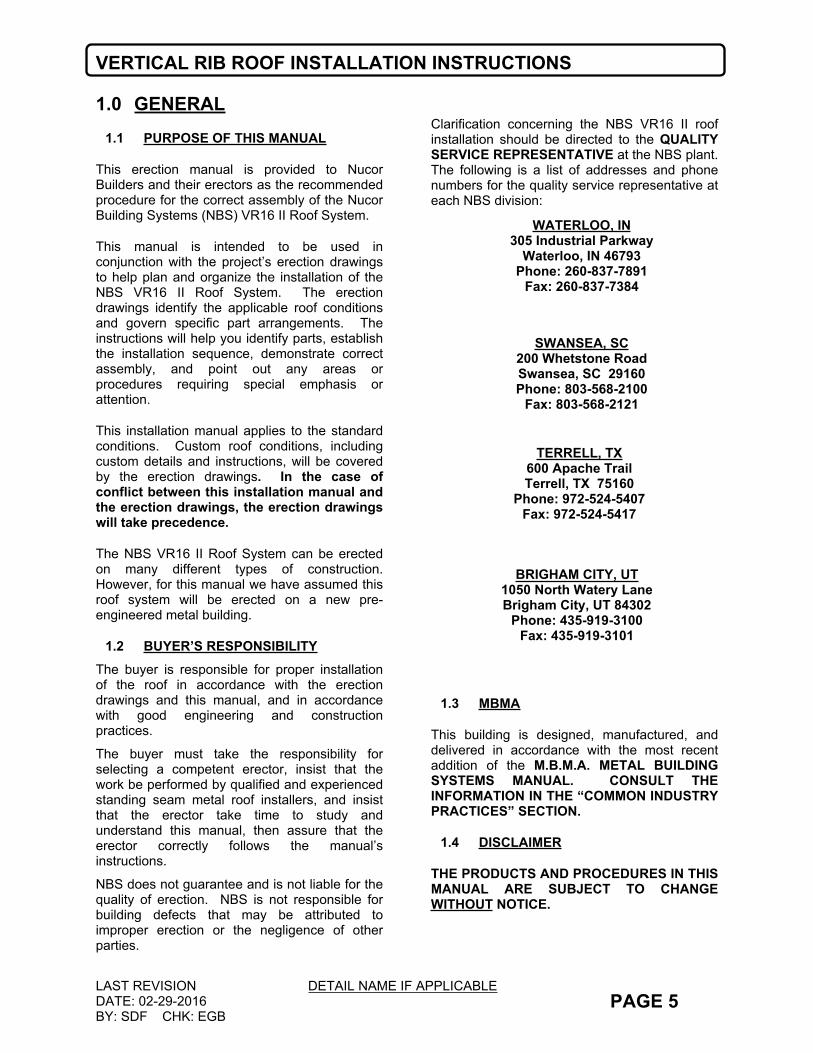
1.0 GENERAL1.1 PURPOSE OF THIS MANUAL
This erection manual is provided to Nucor Builders and their erectors as the recommended procedure for the correct assembly of the Nucor Building Systems (NBS) VR16 II Roof System.
This manual is intended to be used in conjunction with the project’s erection drawings to help plan and organize the installation of the NBS VR16 II Roof System. The erection drawings identify the applicable roof conditions and govern specific part arrangements. The instructions will help you identify parts, establish the installation sequence, demonstrate correct assembly, and point out any areas or procedures requiring special emphasis or attention.
This installation manual applies to the standard conditions. Custom roof conditions, including custom details and instructions, will be covered by the erection drawings. In the case of conflict between this installation manual and the erection drawings, the erection drawings will take precedence.
The NBS VR16 II Roof System can be erected on many different types of construction. However, for this manual we have assumed this roof system will be erected on a new pre-engineered metal building.
1.2 BUYER’S RESPONSIBILITYThe buyer is responsible for proper installation of the roof in accordance with the erection drawings and this manual, and in accordance with good engineering and construction practices.
The buyer must take the responsibility for selecting a competent erector, insist that the work be performed by qualified and experienced standing seam metal roof installers, and insist that the erector take time to study and understand this manual, then assure that the erector correctly follows the manual’s instructions.
NBS does not guarantee and is not liable for the quality of erection. NBS is not responsible for building defects that may be attributed to improper erection or the negligence of other parties.
Clarification concerning the NBS VR16 II roof installation should be directed to the QUALITY SERVICE REPRESENTATIVE at the NBS plant. The following is a list of addresses and phone numbers for the quality service representative at each NBS division:
1.3 MBMA
This building is designed, manufactured, and delivered in accordance with the most recent addition of the M.B.M.A. METAL BUILDING SYSTEMS MANUAL. CONSULT THE INFORMATION IN THE “COMMON INDUSTRY PRACTICES” SECTION.
1.4 DISCLAIMER
THE PRODUCTS AND PROCEDURES IN THIS MANUAL ARE SUBJECT TO CHANGE WITHOUT NOTICE.
BRIGHAM CITY, UT1050 North Watery LaneBrigham City, UT 84302
Phone: 435-919-3100Fax: 435-919-3101
WATERLOO, IN305 Industrial Parkway
Waterloo, IN 46793Phone: 260-837-7891
Fax: 260-837-7384
SWANSEA, SC200 Whetstone RoadSwansea, SC 29160Phone: 803-568-2100
Fax: 803-568-2121
TERRELL, TX600 Apache TrailTerrell, TX 75160
Phone: 972-524-5407Fax: 972-524-5417
VERTICAL RIB ROOF INSTALLATION INSTRUCTIONS
LAST REVISIONDATE: 09-26-2008BY: KMC CHK: EGB
DETAIL NAME IF APPLICABLEPAGE 6
1.5 UNLOADING AND STORING
Check the quantities and condition of all VR16 II bundles and trim crates on arrival. Note on the delivery tickets of any shortages, damage, or discrepancies. NBS shall not be liable for damage or shortages that are not noted on the delivery tickets. The customer assumes full responsibility for the condition of this material after deliver by the trucking company.
Extreme care should be exercised when unloading and handling the panel bundles and accessory crates to prevent damage. The weight of the panel bundle is printed on the bundle tag on the end of each bundle. If the tag is not on the bundle, you may calculate the weight of the bundle with the formula: (Qty. of panels x Bundle length x 2.5 lbs. per foot).
Bundles up to 25 feet long can be lifted with a forklift. Bundles over 25 feet long shall be lifted with a cane utilizing a spreader bar with 4-inch minimum width nylon straps. Straps should be 15 to 20 feet apart. To avoid damage to the panels, steel cables, chains, or chokers shall not be used.
The VR16 II panels and accessories shall be stored on high ground, sloped to drain and tarped to protect from moisture formation. The tarp should be open at each end to allow consistent airflow through the bundles. The recommended procedures are outlined in this manual. NBS will not be held responsible for damage or discoloration of panels caused by improper storage.
1.6 ERECTION SEQUENCE
The Nucor VR16 II™ Roof System is typically designed to be erected from either end of the building. In cases where a panel end lap is needed, the panels must be installed from right to left (looking up the roof slope). Also due to some building layouts, it may be required to start erection from a specific end. In either case, this will be noted as such on the roof sheeting plan.
Because the roof can be started from either end, the panel ribs may not be in alignment across the ridge. This is normal practice for the Nucor VR16 II Roof System and does not affect the performance of the roof system.
For buildings with roof translucent panels, in order to align the translucent panels across the ridge, it is suggested to erect the roof panels on both sides of the ridge from the same end of the building, utilizing the same start panel width. Panel runs with translucent panels have been placed as specified in the order documents.
1.7 COORDINATION WITH OTHER TRADES
Supports for the Nucor VR16 II™ Roof System shall be provided and are required as shown in the sections and as noted in these specifications. All necessary clearance dimensions for proper elevations relative to the roof panels have been shown. The contractor shall be responsible for coordinating these dimensional requirements with other trades associated with the building roof system.

VERTICAL RIB ROOF INSTALLATION INSTRUCTIONS
LAST REVISIONDATE: 01-5-2012BY: DLF CHK: EGB
DETAIL NAME IF APPLICABLEPAGE 7
1.8 ERECTION CAREThe Erector must be skilled in the erection of Metal Building Systems, including roof panels, and is responsible for complying with all applicable local, federal and state construction and safety regulations including OSHA regulations as well as any applicable requirements of local, national, or international union rules or practices.
The Erector remains solely responsible for the safety and appropriateness of all techniques and methods utilized by its crew in the erection of the Metal Building System and/or the VR16 II roof system.
The Erector and/or Contractor is also responsible for supplying safety devices, such as scaffolds, runways, nets, etc. which may be required to safely erect the Metal Building System and/or VR16 II roof system.
The Erector of the Nucor VR16 II™ Roof System shall exercise great care and attention to the details as shown on the erection drawings and in the Nucor VR16 II™ erection manual to insure a secure and proper fit of all components. NBS shall not be responsible for supervising and/or coordinating the erection of the VR16 II Roof System with other trades.
Due consideration must be given by the erector to the effects of thermal expansion and contraction when erecting a roof tie-in to an existing structure to insure a safe, secure, weather-tight condition. Flashing for tie-ins to existing buildings is typically not included as part of the material provided by NBS. Refer to the sections and details for specific materials provided by NBS.
1.9 FIELD CUTTING OF PANELS
When VR16 II roof panels need field cut or mitered, non-abrasive cutting tools such as nibblers or tin-snips shall be used. Abrasive cutting tools such as mechanical grinders or power saws, can damage the galvalume finish and create excess metal shavings that can corrode the panels. The use of non-approved cutting devices may void the factory warranty.
1.10 TRIM AND FLASHING
NOTE: Trim and/or flashing for transitions to existing buildings is not supplied by NBS.
1.11 ENGINEERING AND REINFORCING MATERIALS
NOTE: NBS does not supply engineering investigations or materials to reinforce existing non-Nucor buildings. These type investigations must be submitted to the project engineer of record.

VERTICAL RIB ROOF INSTALLATION INSTRUCTIONS
LAST REVISIONDATE: 09-26-2008BY: KMC CHK: EGB
DETAIL NAME IF APPLICABLEPAGE 8
2.0 DESIGN & PERFORMANCE CRITERIA
2.1 ROOF SYSTEM
The NBS VR16 II Roof System consists of 24 gage panels with a nominal coverage of 1’-4” and a panel seam that is 2” tall. The flat of the panel will be elevated above the top of the roof secondary member by either ½” (if short clips are used) or 1½” (if tall clips are used). Refer to the details and sections on the erection drawings for specific panel clip type.
Different seam types may be used on specific areas of a roof. In all cases, refer to the erection drawing roof sheeting plan and details for seam type and location. Also refer to the Seaming Manual for instructions on proper use of the seaming equipment.
2.2 PANEL CLIP SPACING
The NBS VR16 II Roof System uses a clip to attach the panels to the roof secondary members. Panel clip spacing is as follows:
For VR16 II Roof on a Nucor Building:Clips are required at every purlin and/or joist, location.
For VR16 II Roof on a non-Nucor Building:Maximum clip spacing is to be 5’-0” for purlin roofs, and 5’-6” maximum for joist roof.
2.3 PANEL CLIP FASTENER REQMT’S
NBS standard clip fasteners are designed to fasten to a steel structural member of .060” minimum thickness (16 Ga.). Two fasteners are required to engage the structural member at every panel clip location. Required fastener pullout values are dependent upon project location, size, building code, and loading. Consult Nucor Engineering for project-dependent fastener specifications.
2.4 ROOF TOP UNITS AND CURB SUPPORTS
The NBS VR16 II Roof System is elevated above the top of the roof secondary structural members. Roof curb sub-framing must be elevated above the secondary members to the elevation of the roof panel to avoid potential leak problems. Refer to the details for proper dimensions. Short roof clips require ½” of elevation, while tall roof clips require 1½” of elevation.
The NBS VR16 II Roof System is designed as a floating system. Curb framing and flashing must be designed accordingly to allow the curb system to float with the VR16 II roof during thermal expansion and contraction. Roof curbs shall not span the ridge of a building.
2.5 INSULATION REQUIREMENTS
NBS recommends that insulation be used in all VR16 II Roof applications to avoid problems with condensation forming on the underside of the sheeting. This also provides a buffer between the purlins and the VR16 II roof to eliminate noise and possible damage due to metal-to-metal contact. NBS can supply a noise reducing foam tape for use in limited applications (canopies, etc.) when included as part of the roof order. Refer to the details for foam tape requirements.
VERTICAL RIB ROOF INSTALLATION INSTRUCTIONS
LAST REVISIONDATE: 09-26-2008BY: KMC CHK: EGB
DETAIL NAME IF APPLICABLEPAGE 9
3.0 COMPOSITE VR16 II ROOF SYSTEM
(Applicable for Composite VR16 II Roof Systems)
3.1 PRODUCT DEFINITION
Refer to the sections and details on the erection drawings for specific clip fastening requirements, insulation thickness requirements, and liner deck type.
NBS recommends the roof secondary members be pre-drilled with ¼” diameter holes to accept the panel clip fasteners to avoid potential fastener breakage.
Composite VR16 II Roof without the use of a liner deck is not a NBS standard product application. Due consideration must be given by the engineer of record or architect when this occurs to the effects of condensation. In addition, great care must be taken by the erector to insure that the roof system is erected in a safe, quality manner.
3.2 VAPOR BARRIER
Vapor barrier must be used between the liner decking and the rigid board insulation to prevent condensation. Refer to the erection drawing details.
3.3 INSULATION
Rigid board insulation is used in conjunction with a Composite VR16 II Roof System. The rigid board insulation must be cut to allow free movement of the back-up plates at panel splice and ridge locations
4.0 NUCOR VR16 II ROOF COMPONENTS WITH ENGINEERING
4.1 COMPONENTS WITH ENGINEERING DEFINITION
In a case where NBS is providing the VR16 II Roof System to be used in conjunction with a non-Nucor structure, NBS refers to that as a “Components with Engineering”. This simply means that NBS shall calculate the quantities and lengths for the material required. NBS is performing no engineering study of the existing structure. The engineer of record on the project shall be responsible for coordinating the VR16 II Roof System with the other trades of the project to insure a safe, quality, and proper application of the roof system. NBS does not supply clip fasteners to attach to non-Nucor framing materials.
4.2 DIAPHRAGM
The NBS VR16 II Roof is designed to accommodate thermal expansion and contraction and will NOT act as a diaphragm for resisting lateral load forces or providing lateral stability to the roof structural members. Due consideration for this must be addressed by the project engineer of record. In addition, the VR16 II Roof, because it is designed to float, will not support structural members laterally. When replacing an existing screw down roof, additional bracing may be required to laterally support the members. Engineering and material for these uses shall not be provided by NBS.
4.3 CLIP FASTENING REQUIREMENTS
Refer to section 2.3 “Design and Performance Criteria” for VR16 II Roof panel clip fastening requirements.

VERTICAL RIB ROOF INSTALLATION INSTRUCTIONS
LAST REVISIONDATE: 09-26-2008BY: KMC CHK: EGB
DETAIL NAME IF APPLICABLEPAGE 10
5.0 RECEIVING & HANDLING ROOF MATERIALS
5.1 FIELD STORAGE OF MATERIALS
Upon acceptance of the shipment, the buyer or his representative is responsible for proper handling, storage, and security of the roof materials. NBS is not liable for damage, injury, or loss as a result of improper storage and/or handling.
The roof panel bundles should be stored on the job site in accordance with the following recommendations.a. Store panels in a protected area, out of
standing water and drifting snow, etc. Panel bundles and trim crates should be blocked 12” above grade.
b. Elevate panels with blocking to allow air circulation under the bundle.
c. Slope panels for drainage of moisture from the panels.
d. As necessary, cover panels with waterproof tarp, allowing for air circulation (do not wrap tarp under panel bundle or restrict air movement.
e. Inspect panels daily for moisture accumulation.
f. If panel bundles contain moisture, the panels should be dried and re-stacked. Use care in re-stacking to avoid damage to panels.
g. Opened or re-stacked panel bundles should be secured to prevent wind damage.
h. Bundles should be located over primary structural frame lines, not in the middle of the bay. Blocking should be used between the
purlins/joists at the panel bundle locations. This blocking is not supplied by NBS.
When moving panel bundles, extreme caution should be taken to prevent damage to the panel edges. Uncrated panels should be supported at each end and at 8’ (maximum) spaces.
All bundles or loose panels on the roof should be secured to the roof secondary members at the end of each workday. On steep sloped roofs, provisions should be taken to prevent panels, panel bundles, and/or trim crates from sliding off the roof. Be sure to set panel bundles on the roof in the proper direction for the installation sequence.
Trim and accessories should be stored in a secure area and protected from damage, weather, and theft. Fasteners, mastics, closures, etc. should be stored out of the weather and protected from contamination.
IMPORTANT NOTE: The finish on these panels may not perform as intended if not erected within 90 days from receipt at the job site. The finish is also subject to severe damage if moisture, debris, or dust is allowed to get between the panels; therefore, panels MUST BE STORED UNDER COVER with one end elevated to allow for drainage and protection against moisture, dust, or debris until erected. The manufacturer will not accept claims for non-performing panels if not properly stored at the jobsite. The customer assumes full responsibility for the condition of this material after deliver by the trucking company.
VERTICAL RIB ROOF INSTALLATION INSTRUCTIONS
LAST REVISIONDATE: 09-26-2008BY: KMC CHK: EGB
DETAIL NAME IF APPLICABLEPAGE 11
5.2 HANDLING INDIVIDUAL ROOF PANELS
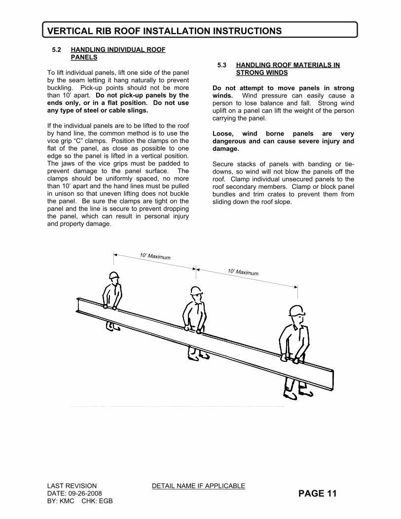
To lift individual panels, lift one side of the panel by the seam letting it hang naturally to prevent buckling. Pick-up points should not be more than 10’ apart. Do not pick-up panels by the ends only, or in a flat position. Do not use any type of steel or cable slings.
If the individual panels are to be lifted to the roof by hand line, the common method is to use the vice grip “C” clamps. Position the clamps on the flat of the panel, as close as possible to one edge so the panel is lifted in a vertical position. The jaws of the vice grips must be padded to prevent damage to the panel surface. The clamps should be uniformly spaced, no more than 10’ apart and the hand lines must be pulled in unison so that uneven lifting does not buckle the panel. Be sure the clamps are tight on the panel and the line is secure to prevent dropping the panel, which can result in personal injury and property damage.
5.3 HANDLING ROOF MATERIALS IN STRONG WINDS
Do not attempt to move panels in strong winds. Wind pressure can easily cause a person to lose balance and fall. Strong wind uplift on a panel can lift the weight of the person carrying the panel.
Loose, wind borne panels are very dangerous and can cause severe injury and damage.
Secure stacks of panels with banding or tie-downs, so wind will not blow the panels off the roof. Clamp individual unsecured panels to the roof secondary members. Clamp or block panel bundles and trim crates to prevent them from sliding down the roof slope.
10’ Maximum
10’ Maximum
VERTICAL RIB ROOF INSTALLATION INSTRUCTIONS
LAST REVISIONDATE: 09-26-2008BY: KMC CHK: EGB
DETAIL NAME IF APPLICABLEPAGE 12
5.4 MATERIAL INVENTORY
Your material is carefully inspected and packaged before leaving the plant and accepted by the transportation company as being complete and in satisfactory condition. It is the carrier’s responsibility to deliver the shipment intact. Note any damage or discrepancies on the delivery tickets before signing as receiver.
Conducting a material inventory at the time of delivery is essential. By conducting the materials inventory, the erector is able to identify any material shortage or damage and avoid stopping installation later because of such shortage or damage. All claims must be filed with NBS Quality Service Representatives prior to any field modifications or purchases that may result in a charge to NBS.
It is imperative that any shortages or damages of the delivered materials be noted at once and clearly marked on the bill of lading before signature of acceptance. Notify NBS immediately of any conflicts. NBS will not be responsible for shortages or damages unless they are noted on the bill of lading. NBS is not responsible for items accepted in questionable condition.
In the case of packaged components (such as clips, fasteners, and mastics, etc.), the quantities are marked on their container and should be checked against the bill of materials.
5.5 EQUIPMENT FOR UNLOADING AND LIFTING
Hoisting equipment is necessary to unload and position the panels and accessory crates for site storage and installation. The equipment must have sufficient capacity and reach to place the material where it is required for efficient installation.
Nylon slings will be required to minimize panel damage. Nucor recommends a minimum 4” wide nylon sling be used. NBS panels are rolled and banded. No exterior covering is used, so care must be taken to prevent damage.
A spreader bar will be required for the longer panel bundles to assure correct sling spacing and uniform lifting. The spreader bar must be large enough to handle the maximum panel bundle weight and length.
Trim crates are to be handled in the same way as panel bundles.
Panel bundle weight can be found on the I.D. tag at the low end of each bundle. Steel chokers, cables or chains shall not be used.
5.6 LIFTING ROOF PANEL BUNDLES
Bundles over 25 feet long should be handled with a crane using a spreader bar and nylon slings. Lifting should occur at center of gravity. Locate slings at ¼ points of the length of the panel from each end of the bundle.
Loads should always be checked for secure hook-up, proper balance, and lift clearance. Tag lines should be used if to control the load during lifting, especially if operating in the wind.
Panel crates less than 25’ long may be lifted with a forklift only if the forks are spread at least 5’ apart and blocking is used to prevent panel damage by the forks.
VERTICAL RIB ROOF INSTALLATION INSTRUCTIONS
LAST REVISIONDATE: 09-26-2008BY: KMC CHK: EGB
DETAIL NAME IF APPLICABLESSEM0050.dwg PAGE 13
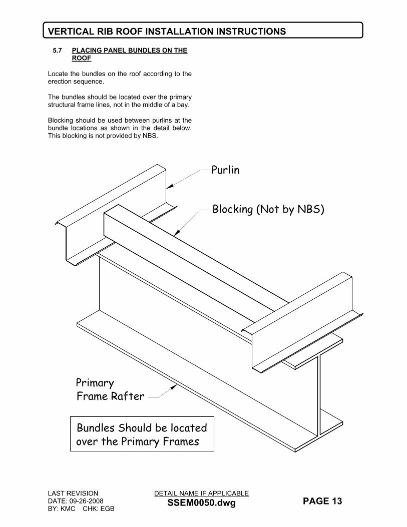
5.7 PLACING PANEL BUNDLES ON THE ROOF
Locate the bundles on the roof according to the erection sequence.
The bundles should be located over the primary structural frame lines, not in the middle of a bay.
Blocking should be used between purlins at the bundle locations as shown in the detail below. This blocking is not provided by NBS.

VERTICAL RIB ROOF INSTALLATION INSTRUCTIONS
LAST REVISIONDATE: 09-26-2008BY: KMC CHK: EGB
DETAIL NAME IF APPLICABLEPAGE 14
6.0 SAFE ROOF INSTALLATION
6.1 REGULATIONS
Regulations set forth by the Occupational Safety and Health Act, local, state, and/or federal agencies should be adhered to at all times. NBS is not responsible for injury, damage, or failure, which may be the result from failing to meet any of these regulations.
In compliance with the Hazard Communication Rule 1910:1200, Material Safety Data Sheets (MSDS) have been provided for your use and safety. These data sheets should be made available to all personnel that come in contact with these products. These data sheets will give you the necessary information to properly handle such materials and what to do in case of an emergency. (The MSDS sheets are located in one of the warehouse boxes for non-Nucor builders, and in the office of Nucor Builders).
6.2 ERECTOR’S RESPONSIBILITY
The erector of the roof system is responsible for the safe execution of this manual. These instructions are intended to describe the sequence and proper placement of parts. They are not intended to prescribe comprehensive safety procedures. The procedures in this
manual are believed to be reliable. However, NBS shall not be responsible for injury, damage, or failure due to the misapplication of these procedures, improper erection techniques, or negligence
6.3 WALKING AND WORKING ON ROOF PANELS
DO NOT place bundles of panels on the roof structure without first verifying the structure will safely support the concentrated weight of the panels and the weight of the installation crew. Some roof structures may not be designed to support the weight of a full panel bundle without additional structure support.
DO NOT use a roof panel as a working platform. An unsecured panel could collapse under the weight of a person standing between purlins or at the panel end.
DO NOT walk on the last installed panel run, as the unsecured edge could collapse under a person’s weight. When installing clips or making end lap connections, etc., stand where the roof structural will support your weight.
An approved and safe walking platform should be used in high traffic areas to prevent the roof panel from being deformed, scratched, or scuffed.
VERTICAL RIB ROOF INSTALLATION INSTRUCTIONS
LAST REVISIONDATE: 09-26-2008BY: KMC CHK: EGB
DETAIL NAME IF APPLICABLEPAGE 15
6.4 SAFETY EQUIPMENT
The use of safety equipment for the roof panel installation is recommended at all times during the installation process. However, when using lanyards, be sure that the clasp, belt hooks and wire cables are covered in such a manner that they will not scratch the panel surface if accidentally dragged along the panel.
6.5 CREW SIZE
The length of the individual roof panels should be considered when determining crew size. It is recommended that under normal conditions, there be one person for every ten feet of panel length, plus one.
6.6 PANEL OVERHANG
DO NOT stand on the end of unsupported (cantilevered) panels at the eave or ridge. Standing on the cantilever portion may result in panel collapse.
6.7 POINT LOADS
When properly supported by the structural steel, panels are designed to support uniform loads, which are evenly distributed over the panel surfaces. Point loads that occur in small or concentrated areas, such as heavy equipment, ladder, or platform feet, etc., may cause panel deformation or even panel collapse.
6.8 SLICK SURFACES
Panel surfaces and structural steel surfaces are hard, smooth, and nonabsorbent, which causes these surfaces to be very slick when wet or covered with snow or ice. Even blowing sand or heavy dust can make these surfaces difficult to walk on without slipping.
Unpainted panel surfaces are often coated with oil to accommodate the panel-fabrication process. Although designed to wash away or evaporate during normal weather, the oil on new panels can be extremely slick, especially during periods of light rain and dew.
Caution must be exercised to prevent slipping and falling onto the roof surface or even sliding off the roof. Non-slip footwear is a necessity and non-slip working platforms are recommended.
6.9 ELECTRICAL CONDUCTANCE
Metal panels are excellent electrical conductors. A common cause of injury is the contact of metal panels with power lines during handling and installation. The location of all power lines must be noted and, if possible, flagged. The installation process must be routed to avoid accidental contact with all power lines and high voltage services and equipment. All tools and power cords must be properly insulated and grounded and the use of approved ground fault circuit breakers is recommended.
6.10 FALSE SECURITY OF INSULATION
Blanket and rigid board insulation block the installer’s view of the ground below the roof. Serious injury can occur when the installer gets a false sense of security because he cannot see the ground and steps through the insulation.
6.11 SHARP EDGES
Some edges or panels and flashing are razor sharp and can cause severe cuts if proper protective hand gear is not worn. Be careful not to injure others while moving panels and flashing.

VERTICAL RIB ROOF INSTALLATION INSTRUCTIONS
LAST REVISIONDATE: 01-28-2010BY: EGB CHK: KMC
DETAIL NAME IF APPLICABLEPAGE 16
6.12 SAFE ROOF INSTALLATION SUMMARY
EXTREME CAUTION SHOULD BE EXERCISED WHEN WALKING ON ROOF PANELS.
OILS USED DURING THE ROLL FORMING PROCESS AND/OR NATURAL MOISTURE MAY CAUSE THE PANELS TO BECOME SLIPPERY.
DO NOT STEP ON PANELS WITH CREASED EDGES.
DO NOT STEP ON OR NEAR THE EDGE OF A PANEL.
DO NOT STEP WITHIN 5 FEET OF THE END OF A PANEL.
DO NOT USE LOOSE PANELS AS WORK PLATFORMS.
DO NOT WALK ON UNSECURED PANELS.
DO NOT WALK ON TRANSLUCENT PANELS
SECURE ALL LOOSE PANELS AT THE END OF THE WORK DAY.
USE EXTRA CARE WHEN WORKING ON STEEP SLOPES.
WHEN INSTALLING CLIPS, WALK ONLY OVER THE PURLIN/JOIST LINES.
AS ROOF WORK PROGRESS’S, ALL FULL PANELS RUNS SHOULD BE MOTOR SEAMED. SEE PAGE’S 25 & 59 FOR TEMPORARILY HAND CRIMPING INFORMATION.
IN COMPLIANCE WITH THE HAZARD COMMUNICATION RULE 1910:1200, MATERIAL SAFETY DATA SHEETS HAVE BEEN PROVIDED FOR YOUR USE AND SAFETY. THESE DATA SHEETS SHOULD BE MADE AVAILABLE TO ALL PERSONNEL THAT COME IN CONTACT WITH THESE PRODUCTS. THESE DATA SHEETS WILL GIVE YOU THE NECESSARY INFORMATION TO PROPERLY HANDLE SUCH MATERIALS AND WHAT TO DO IN CASE OF AN EMERGENCY.
VERTICAL RIB ROOF INSTALLATION INSTRUCTIONS
LAST REVISIONDATE: 09-26-2008BY: KMC CHK: EGB
DETAIL NAME IF APPLICABLEPAGE 17
7.0 CHECKING THE STRUCTURE
7.1 COMPLETED AND BRACED
Before placing materials and workers on the roof structure to start roof installation, it must be confirmed that the structure is designed to accommodate the material and erection loads as well as the appropriate live loads and wind uplift loads.
It also must be determined that the structure is complete and structurally sound with all structural connections and bracing in place and secure.
7.2 LATERAL STABILITY
The sliding clip method of attaching roof panels to the roof secondary members provides only limited lateral stability and diaphragm bracing to the roof secondary members.
Before placing materials on the roof and starting the roof installation, confirm that the necessary roof bracing and sag angles or bridging is in place and secured.
7.3 ALIGNMENT
Prior to installation, roof secondary members should be checked for overall dimensions and evenness of plane. The roof secondary members should also be checked to verify the roof system can be installed without interference. Also, roof secondary members nearest the panel end laps, ridge, or high eave should be checked for correct location to properly accommodate the roof components.
7.4 TOLERANCES
To assure the roof system’s correct fit-up and designed weather tightness, the structure must be aligned within the following tolerances; also refer to the MBMA manual for common industry standards.
OUT OF SQUARE – The roof system can only accommodate 1/8” of “sawtooth” of the roof panel ends and the eave, ridge, and panel splices. This means the allowable out of square
of the rake line relative to the eave line and ridge line is 1/8” for each 40’ of rake run.
STRUCTURE WIDTH AND EAVE STRAIGHTNESS – The roof system is designed to accommodate +/- 1” of overall structure width error, or +/- 3/4” of eave straightness error at each eave.
To assure that the accumulation of the structure width error and eave straightness error does not exceed the roof system’s tolerance, the structure width should be measured from eave line to eave line at each rake, at the first frame line from each rake and at each point where there is a significant error or change in eave straightness (this usually occurs at a frame line or at a wind column).
STRUCTURE LENGTH AND RAKE STRAIGHTNESS – The roof system is designed to accommodate +/- 2” of overall structure length error, or +/- 1” of rake straightness error at each rake line.
To assure that the accumulation of the structure length error and rake straightness error does not exceed the roof system’s tolerance, the structure length should be measured from rake line to rake line at each eave, at the ridge and at each point where there is a significant error or change in rake straightness (this usually occurs at a rafter end splice).
7.5 MEASURING
Structure length and width may be measured with a steel measuring tape from the face of the eave or rake member to the face of the opposite eave or rake member. The measuring tape must be parallel to the relative eave or rake line and must be stretched taut. Eave and rake straightness may be determined by measuring deviations from a string line, which is stretched taut along the eave or rake line.
7.6 AESTHETIC ACCEPTANCE
Although these structure alignment tolerances will allow for reasonable roof component fit-up and ease of installation, the extremes of these tolerances may be aesthetically objectionable and should be confirmed with the customer before starting the roof installation.

VERTICAL RIB ROOF INSTALLATION INSTRUCTIONS
LAST REVISIONDATE: 09-26-2008BY: KMC CHK: EGB
DETAIL NAME IF APPLICABLEPAGE 18
7.7 CORRECTIONS
Any structure alignment error, which exceeds the above stated tolerances, must be corrected before roof installation can begin. If it is decided that the structure alignment errors cannot be corrected, alternate roof details may have to be developed. The alternate details may require additional materials, modified parts (with additional cost, fabrication and delivery time) and additional installation time. NBS cannot assure the performance of such alternate details.
8.0 INSTALLATION BASICS8.1 PROPER TOOLS
Before starting the roof installation, be sure that the proper equipment and tools are on hand. The tools must be in good operating condition and operators should adhere to safety precautions at all times.
The following tools and equipment should be considered for efficient installation of the NBS VR16 II Roof System. Actual tools and equipment required may vary due to variations in building type and construction:
Motorized Seaming Machine NBS VR16 II Manual Crimping Tool Screw Guns-designed for use with
self-drilling screws Socket Extensions-6” for screw guns Hex Socket Heads-5/16” and 3/8”,
magnetic Electric Drill Motor-1/4” capacity Drill Bits-assortment Sheet Metal Cutter-or power shears
or nibblers VR16 II Rib Clamp(s)
o Available for Purchase from NBS
Pop Rivet Tool-1/8” capacity
Sheet Metal Shears-left and right cut Hack Saw-with metal cutting blade Steel Measuring Tapes-12’, 50’, 100,
and120’ Nylon String Lines Blue Chalk Line (Not Red) Brooms Marking Pens (do not use pencils) Caulk Guns-for 1/10-gallon mastic
tubes Power Source and Extension Cords-
capable of handling the total equipment requirement, including 20-amp seaming machine, without power drop due to extension cord length.
8.2 MASTIC
TEMPERATURE EFFECTSTemperature extremes must be considered during installation of the roof due to the sensitivity of mastics. The recommended installation temperature range is 20-120 degrees Fahrenheit. At colder temperatures, the mastic stiffens resulting in loss of adhesion and compressibility. At hotter temperatures, the mastic becomes too soft for practical handling. On cold but sunny days, the panel surface may become warm enough to accept the application of heated mastic even though the air temperature is below 20 degrees Fahrenheit.
When overnight temperatures fall below freezing, the mastic should be stored in a heated room so it will be warm enough to use the following day. On hot days, the mastic cartons should be stored off the roof in a cool and shaded area. While on the roof, mastic rolls should be kept shaded until actual use.
In very cold weather, it is recommended that the fasteners be tightened slowly and only tight enough that the mastic is in full contact with the panel or flashing. Then on the next sunny day, complete the tightening process after the sun warms the panel and flashing surfaces.

VERTICAL RIB ROOF INSTALLATION INSTRUCTIONS
LAST REVISIONDATE: 09-26-2008BY: KMC CHK: EGB
DETAIL NAME IF APPLICABLEPAGE 19
CONTAMINATIONTo assure proper adhesion and sealing, the mastic must have complete contact with adjoining surfaces. Contaminants such as water oil, dirt and dust prevent such contact. The panel and flashing surfaces must be dry and thoroughly cleaned of all contaminants. Before applying tape mastic, the mastic should be checked for contaminants. If the mastic surfaces are contaminated, it must not be used.
During cool weather, condensation or light mist can accumulate on the panel and flashing surface and not be easily noticed. It is recommended that the mastics always be kept under protective cover and that the panel and flashing surfaces be wiped dry immediately before installation.
Tape mastic is provided with a protective paper to reduce contamination. Incomplete removal of the protective paper will prevent the mastic adhesion to the panel or flashing surfaces. Always check that the protective paper is completely removed. DO NOT remove the protective paper until immediately before the panel or flashing is installed over the mastic.
COMPRESSIONTo assure proper compression and seal, the tape mastic must be compressed between the
panel and flashing surfaces with firm and uniform pressure. In most cases, the required pressure is applied by the clamping action of screws pulling the adjoining surfaces together. However, the tape sealant’s resistance to pressure becomes greater in cold weather.
During cold weather, the fasteners must be tightened slowly to allow the mastic time to compress. If the fasteners are tightened too fast, the fasteners may strip out before the mastic compresses adequately, or the panel or flashing may deform in the immediate area of the fastener, leaving the rest of the mastic insufficiently compressed.
INSIDE CORNERSAn inside radius, such as where the panel flat meets a rib, is usually the most critical area to seal. A common mistake for the installer is to bridge the mastic across the inside radius.
When the lapping panel or flashing is pushed into place, the bridged mastic is stretched and thinned. The mastic may then be too thin to adequately seal this critical area. When tape mastic is applied at an inside radius, it is recommended that the mastic be folded back, then push the mastic fold into the radius.
VERTICAL RIB ROOF INSTALLATION INSTRUCTIONS
LAST REVISIONDATE: 09-26-2008BY: KMC CHK: EGB
DETAIL NAME IF APPLICABLEPAGE 20
8.3 FASTENERS
SCREW GUNSUse torque control screw guns for driving self-drilling screws. 2000-2500 RPM screw guns with torque adjustable clutch are necessary to attain efficient drilling speeds. High tool amperage (6-7 AMP) is required to achieve the proper torque for secure fastening. Do not use impacting tools. Also note that cordless screw guns will not work.
To assure proper voltage to the tool, extension cords should be checked for proper wire size and cord length:
16 ga. wire, max cord length = 100’ 14 ga. wire, max cord length = 200’ 12 ga. wire, max cord length = 300’
SOCKETSUse good quality magnetic sockets. Good fitting sockets reduce wobble and stripping of the screw heads. They also minimize objectionable paint chipping and scuffing on colored screws and minimize damage to the protective coating on unpainted screws.
Magnetic sockets collect drill shavings, which will build up and eventually prevent the socket from seating properly on the screw heads. One method of removing the drill shavings is to roll up a ball of tape mastic and push the socket into the mastic.
When the socket is removed from the mastic, most of the drill shavings will be embedded in the mastic thereby cleaning the socket. This process should be repeated as often as needed to keep the socket clear of drill shavings.
SOCKET EXTENSIONSA 4” or 6” socket extension is recommended for installing the panel clip screws. With the extension, the screw can be driven straight down without tilting the screw gun to clear the panel or clip.
INSTALLATIONBefore starting the screw, the materials to be joined must be pressed together with foot or
hand pressure. The pressure must be maintained until the screw has drilled through all the materials and the threads have engaged.
Most self-drilling screws require 20 pounds of pressure to maintain the drilling action and to start the thread cutting action. Also, applying such pressure before starting the screw gun will usually prevent tip walking or wandering. If too little pressure is applied, the drill point may not cut into the metal and the point will heat up and become dull. If the pressure is too heavy, the bottom material may be deflected away, causing a standoff condition, or the drill tip may be broken or split. Screws must be held perpendicular to the panel or flashing surface during starting and driving.
For proper seating of the fastener-sealing washer, the panel of flashing surface must be clean and drill shavings must be removed from under washers before seating. The fastener must be driven perpendicular to the panel surface so that the washer can seat level without warping or cupping.
Do not over-drive screws. Over-driving can strip the threads and/or damage the sealing washer. Use screw gun with torque control set to function properly for the combination of fastener size, hole size, and material thickness.
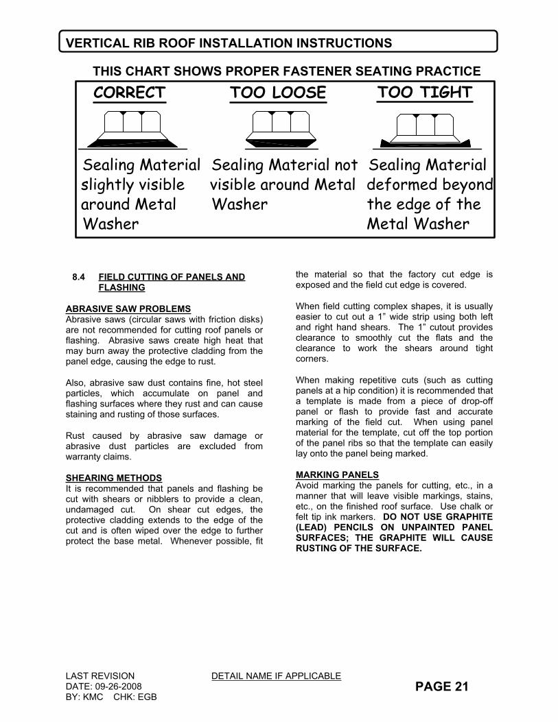
The fastener should be driven tight enough to uniformly compress the washer but not so tight that the washer splits or rolls out from under its metal dome. The recommended procedure is to tighten the fastener until the sealing washer just starts to visually bulge from under the metal dome. Refer to the chart on the following page for a proper fastener-seating diagram.
As a standard practice, NBS provides oversized (goof) screws. Upon stripping or breaking a screw, the screw must be immediately removed and replaced with the goof screw. Do not defer the screw replacement to be remembered and fixed later, or to be found by the clean-up crew. The majority of such screws are easily overlooked until they cause leak problems later.
VERTICAL RIB ROOF INSTALLATION INSTRUCTIONS
LAST REVISIONDATE: 09-26-2008BY: KMC CHK: EGB
DETAIL NAME IF APPLICABLEPAGE 21
THIS CHART SHOWS PROPER FASTENER SEATING PRACTICE
Sealing Material slightly visible around Metal Washer
Sealing Material not visible around Metal Washer
Sealing Material deformed beyond the edge of the Metal Washer
CORRECT TOO LOOSE TOO TIGHT
8.4 FIELD CUTTING OF PANELS AND FLASHING
ABRASIVE SAW PROBLEMSAbrasive saws (circular saws with friction disks) are not recommended for cutting roof panels or flashing. Abrasive saws create high heat that may burn away the protective cladding from the panel edge, causing the edge to rust.
Also, abrasive saw dust contains fine, hot steel particles, which accumulate on panel and flashing surfaces where they rust and can cause staining and rusting of those surfaces.
Rust caused by abrasive saw damage or abrasive dust particles are excluded from warranty claims.
SHEARING METHODSIt is recommended that panels and flashing be cut with shears or nibblers to provide a clean, undamaged cut. On shear cut edges, the protective cladding extends to the edge of the cut and is often wiped over the edge to further protect the base metal. Whenever possible, fit
the material so that the factory cut edge is exposed and the field cut edge is covered.
When field cutting complex shapes, it is usually easier to cut out a 1” wide strip using both left and right hand shears. The 1” cutout provides clearance to smoothly cut the flats and the clearance to work the shears around tight corners.
When making repetitive cuts (such as cutting panels at a hip condition) it is recommended that a template is made from a piece of drop-off panel or flash to provide fast and accurate marking of the field cut. When using panel material for the template, cut off the top portion of the panel ribs so that the template can easily lay onto the panel being marked.
MARKING PANELSAvoid marking the panels for cutting, etc., in a manner that will leave visible markings, stains, etc., on the finished roof surface. Use chalk or felt tip ink markers. DO NOT USE GRAPHITE (LEAD) PENCILS ON UNPAINTED PANEL SURFACES; THE GRAPHITE WILL CAUSE RUSTING OF THE SURFACE.

VERTICAL RIB ROOF INSTALLATION INSTRUCTIONS
LAST REVISIONDATE: 09-26-2008BY: KMC CHK: EGB
DETAIL NAME IF APPLICABLEPAGE 22
8.5 SHEETING DIRECTION AND MODULARITY
Although the NBS VR16 II Roof System is designed so it can be installed either direction (left to right or right to left), there may be roof conditions that require a specific sheeting direction. If panel end laps are needed, the panels must be installed from right to left (looking up the roof slope). Check the erection drawings to determine if a specific sheeting direction is required. The required installation sequence is to complete each panel run from eave to ridge before starting the next panel run. This sequence will help ensure straight runs and allow the insulation to be installed immediately ahead of each panel run.
During installation of the roof, considerations must be made for maintaining panel modularity. By maintaining panel modularity, proper roof coverage can be obtained and the standard perimeter parts will fit properly without necessity of field modifications or reordering of parts, etc.
For proper fit-up between the panel, mastic and closures or end lap parts, the panels must be held to the 16” coverage dimension (within a 1/8” tolerance per panel). The accumulated coverage (start panel to finish panel) tolerance is determined by the ability to keep the panels parallel and to correctly fit and assemble the finish rake condition.
If the roof panel has conditions such as fixed location penetrations, parapets, firewalls, etc., the accumulated panel coverage may require tighter tolerances for proper fit-up and weather-tightness of the roof system.
Maintaining panel modularity is EXTREMELY IMPORTANT, as the panels may shrink or grow during installation. Refer to section 13.5 and 13.6 for further instructions and details about holding panel modularity.
8.6 LAYOUT AND CHECKING COVERAGE
Recommended for all roofs, but a must for large or complex roofs, is to make a layout of the actual structure (field measured as described in sections 7.4-7.5) so that the roof panel start and stop dimensions can be laid out to accommodate any structural misalignments.
Panel coverage is always checked at the eave, ridge, and end laps so that non-parallel seam (or dogleg) conditions can be detected and corrected before they become objectionable. The coverage check should be one with a measuring tape held taut and measured to the same side of the seam and always parallel to the eave to prevent any measuring error.
Every four to six panel runs should be checked for panel modularity. This will assure that the panels are maintaining a straight line and proper coverage is being maintained. If the panels are off module, they should be corrected by equal adjustments of the next four to six panel runs.
8.7 APPEARANCE CONSIDERATIONS
Although the above stated coverage tolerance will provide for reasonable ease of installation and water tightness, such visible conditions as non-parallel panel seams, dogleg of the panel seam at the end laps, non-parallel finish panel width, and mismatch of panel seams across the ridge, may be objectionable and should be confirmed with the customer before continuing roof installation.
VERTICAL RIB ROOF INSTALLATION INSTRUCTIONS
LAST REVISIONDATE: 09-26-2008BY: KMC CHK: EGB
DETAIL NAME IF APPLICABLEPAGE 23
8.8 INSPECTION OF THE ROOF ASSEMBLY DURING INSTALLATION
IMPORTANCE OF INSPECTIONDuring the roof installation, all areas of the roof system assembly must be frequently inspected to ensure the correct assembly in accordance with the erection drawings and this manual.
Failure to assemble the roof system correctly will result in roof performance problems that may require costly corrective work, roof replacement and performance and damage claims, etc. Also, incorrect installation may void the material and weather-tightness warranties.
8.9 INSPECTION LIST
ERECTION DRAWINGSCheck that the erection drawings are available at the job site and have been reviewed for differences with the actual job conditions and differences with the erection manual. Also confirm that the drawings are the latest issue with the latest revisions and additions.
ROOF LAYOUTSCheck that the roof start and finish dimensions have been correctly determined based on the erection drawings and the actual structural conditions.
STRUCTURAL ALIGNMENTCheck that the structural misalignments were corrected in accordance with section 7.3 of this manual.
PANEL LENGTHCheck that the installed roof panels have the correct overhang at the eave and end laps and have the correct hold back dimension at the ridge or high eave, in accordance with the erection drawings.
EAVE SEALCheck that the eave mastic is in the correct position on top of the eave plate. Check that the eave fasteners penetrate the center of the eave mastic and into the eave plate. Check that the fasteners are not loose or stripped.
Check that the eave mastic is in complete contact with the roof panel and eave plate without any voids or gaps. Confirm that the roof panel and eave plate are clean and dry during installation and that the mastic is not wet or otherwise contaminated.
END LAP SEALCheck that the roof panel end laps are correctly assembled and that the lapping panels are tightly nested without visible gaps.
Check that the mastic is in the correct position and is in complete contact with the lapped panels without any voids or gaps, especially at the radius between the panel flat and the vertical legs of the panel. Confirm that the panels are clean and dry during installation and that the mastic is not wet or otherwise contaminated.
Check that the end lap fasteners penetrate through the center of the mastic and into the lap stiffener. Check that the fasteners are not loose or stripped.
Check that the end lap assembly is not bowed down causing water ponding and debris accumulations.
RIDGE / HIGHSIDE SEALCheck that the zee closure is installed correctly.
Check that the mastic is in the correct position and is in complete contact with the zee closure and the roof panel without any voids or gaps. Confirm that the zee closure and roof panels are clean and dry during installation and the mastic is not wet or contaminated.
Check that the zee closure fasteners penetrate through the roof panel, through the center of the mastic and into the zee closure. Check that the fasteners are not loose or stripped.
Check that the tube caulk is installed along the back of the zee closure as necessary to seal any voids around the panel seam area.

VERTICAL RIB ROOF INSTALLATION INSTRUCTIONS
LAST REVISIONDATE: 09-26-2008BY: KMC CHK: EGB
DETAIL NAME IF APPLICABLEPAGE 24
RAKE SEALCheck that the mastic between the rake trim and the roof panel is properly installed.
Check that the end caps are installed properly.
Check that the flashing splices are correctly lapped, sealed, and fastened.
Check that all fasteners are seated properly.
PANEL CLIP ATTACHMENTCheck that the panel clips are correctly fitted to the panel without any distortion or damage of the clip tab. On sliding clips, check that the clip tab is centered on the clip base between the centering tabs.
Check that the clips are located along each panel side lap at each roof secondary member or at the locations specified on the erection drawings.
Check that the panel clip fasteners are of the type, size, length, finish and quantity per clip as specified on the erection drawings.
Check that the panel clip fasteners are not loose or stripped. In the case of composite VR16 II construction, verify that the fasteners penetrated and engaged the specified roof secondary member.
SIDE LAPCheck that the factory installed side lap mastic is in the correct position without voids or interruptions and is not damaged, wet or otherwise contaminated.
Check that the full length of each side lap seam is correctly seamed.
Check that the panel coverage tolerance does not exceed 1/8” per panel and that the accumulated coverage will allow proper fit and assembly of the ridge closure zee and finish rake condition and any other critical fit conditions such as penetrations, parapets, etc.
FLASHING AND PENETRATIONSCheck that all flashing (including penetrations) are correctly assembled and tightly fitted. Check that the required mastics are correctly positioned and in complete contact with the adjoining surfaces without voids or interruptions. Confirm that the mastics and adjoining surfaces are clean and dry during installation
Check that the flashing splices are correctly lapped, sealed and fastened.
Check that the flashing is sufficiently pitched to shed water and eliminate ponding areas, especially at the critical splices, end laps and corners.
Check that the fasteners are of the specified type, size, length, finish and spacing. Check that the fasteners are not loose or stripped. Check that the sealing washers are in full contact with the flashing surface and not distorted, split or otherwise damaged.
Along the rakes, high eave transitions, fixed penetration, etc., check that the flashing is not constrained and will allow for the roof’s expansion/contraction movement.
VERTICAL RIB ROOF INSTALLATION INSTRUCTIONS
LAST REVISIONDATE: 08/06/2019BY: EGB CHK: KMC
DETAIL NAME IF APPLICABLEPAGE 25
SURFACE CONDITIONSDamaged roof system surfaces are subject to corrosion and performance problems and may void the material and performance warranties.
Check that the panel and flashing surfaces are not being subjected to abusive conditions such as: careless handling of panels and flashing, excessive roof traffic, abrasive or contaminated footwear, rough handling of materials, tools and equipment, or contact with abrasive materials or residue, etc.
Check that the panel and flashing surfaces are not being subjected to exposed metal objects and material left on the roof such as: tools, material drop-off, fasteners, wire, staples, drill and nibbler chips, saw and file particles, etc. In the process of rusting, these materials will absorb the panel’s protective coating, thus leaving the panels exposed to rusting.
Check that the panels and flashing are not being subjected to long term wet conditions such as: standing water, consistent sources of steam, mist, spray, dripping or runoff, wet debris, wet insulation or other moisture holding material.
Check that the panels and flashing are not subjected to direct contact or runoff from corrosive materials such as: copper pipes and flashing, uncured cement, treated lumber, anti-icing chemicals, galvanized materials, strong solvents or other corrosive materials.
Check that graphite (lead) pencils were not used to mark on unpainted surfaces. The graphite marks will cause rusting.
Check that the roof materials are not subjected to damaging heat such as: cutting torches, abrasive saws, etc.
UNSPECIFIED MATERIALSUse of the wrong materials may cause installation and performance problems and may void the performance and material warranties.
Check that all installed roof system materials, especially mastics and fasteners, are only those which are provided or specified by NBS for your specific project and are used only as a specified on the erection drawings and this installation guide.
NBS cannot be responsible for the performance of roof materials that are not provided, specified or approved by NBS.
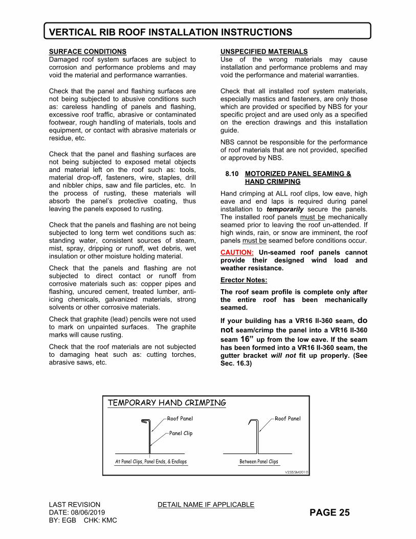
8.10 MOTORIZED PANEL SEAMING & HAND CRIMPING
Hand crimping at ALL roof clips, low eave, high eave and end laps is required during panel installation to temporarily secure the panels. The installed roof panels must be mechanically seamed prior to leaving the roof un-attended. If high winds, rain, or snow are imminent, the roof panels must be seamed before conditions occur.
CAUTION: Un-seamed roof panels cannot provide their designed wind load and weather resistance.Erector Notes: The roof seam profile is complete only after the entire roof has been mechanically seamed.
If your building has a VR16 II-360 seam, do not seam/crimp the panel into a VR16 II-360 seam 16” up from the low eave. If the seam has been formed into a VR16 II-360 seam, the gutter bracket will not fit up properly. (See Sec. 16.3)
Panel Clip
Roof Panel
TEMPORARY HAND CRIMPING
Roof Panel
VERTICAL RIB ROOF INSTALLATION INSTRUCTIONS
LAST REVISIONDATE: 09-26-2008BY: KMC CHK: EGB
DETAIL NAME IF APPLICABLEPAGE 26
8.11 ROOF LEAK TROUBLESHOOTING & POTENTIAL CAUSES OF ROOF LEAKS
The erector does not locate and read the NBS VR16 II erection manual and erection drawing instructions.The erection manual defines the standard details required for installing the NBS VR16 II Roof System. The manual and erection drawings are shipped in a warehouse crate clearly stamped, “OPEN ME FIRST”. Reading the erection manual and drawings will actually improve the productivity and quality of your work. We have included the benefit of years of testing and feedback from many installers who have installed millions of square feet of NBS VR16 II Roof. Be cautious with anyone who tells you that their experience allows them to deviate from the tried and true instructions found in our erection manual and erection drawings.
The building insulation is not properly tied off to form a vapor barrier, allowing the roof to condensate.Condensation occurs when warm moist air comes in contact with colder surfaces such as panels, framing members, etc. The insulation system must be designed to act as a vapor barrier in addition to providing thermal values. It is the erector’s responsibility to install the insulation properly, according to normal and customary industry practices.
The lap stiffener at the end lap is not properly installed or aligned.If the tabs on the lap stiffener are not properly attached over the end of the roof panels, the lap stiffener will push away and not allow the end lap fastener to engage properly.
The pre-cut mastic at the end lap is not properly located over the dimples at the end of the upper panel.The end lap mastic is provided wide enough to cover the dimples in the end of the upper panel. It is important that the mastic is centered over the dimples, so the fastener penetrates the mastic.
Stripped fasteners at end laps, joints, rake, eave, ridge, etc.NBS provides oversize fasteners (H1000) to be used when end lap fasteners are stripped. It is important that if a fastener is stripped, it is replaced with one of a larger size to ensure the proper tightening and clamping force is achieved.
The zee closure is not properly installed.If the proper installation procedure is not followed the panel will not be sealed and moisture build up from ice and snow or a driving rain may infiltrate the building. Refer to the NBS erection manual section (13.8) for instructions. The zee closures need to be aligned, fastened together and sealed with butyl tube caulk.
Butyl Tube Caulk is not applied properly at the Low Eave.Butyl tube caulk is to be placed between the panels at the low eave of the building. Refer to section (11.3 & 12.4) of the NBS erection manual.
Butyl Tube Caulk is not applied properly at the High Eave/Ridge.Butyl tube caulk is to be placed between the panels at the low eave of the building. Refer to section (13.3) of the NBS erection manual.
Incorrect caulking type used at roof locations.NBS provides two types of tube caulking. A non-skinning butyl caulk is supplied for all roof applications, and a skinning polyurethane caulk is supplied for trim applications. The polyurethane caulk is not to be used in roof applications.
Holes in the roof panelsMost of the time, holes in roof panels are from objects being dropped or thrown onto the panels. These include screw guns, roof accessories, clips, etc. Small holes can be patched with a piece of galvalume material sealed with tape mastic and screwed in place. Larger holes should be repaired by replacing the roof panel.

VERTICAL RIB ROOF INSTALLATION INSTRUCTIONS
LAST REVISIONDATE: 09-26-2008BY: KMC CHK: EGB
DETAIL NAME IF APPLICABLEPAGE 27
9.0 STANDARD HARDWARE PARTS
9.1 GENERAL
The following details provide a basic description and graphic illustrations of the standard roof assembly parts. The purpose of these details is to assist the erector in the correct selection and identification of parts.
Because of the many variations in conditions, it is important that you review the job conditions to identify the specific parts required for your job.
Review the erection drawings for any special parts or parts which are different from the standard parts shown in these details. If differences exist, the erection drawings will take precedence.
For proper fit-up, sealing and fastening and to help ensure the roof assembly’s weather-tightness, structural capability, durability and appearance, the correct parts must be used. Do not use parts other than those specified on the erection drawings.

VERTICAL RIB ROOF INSTALLATION INSTRUCTIONS
LAST REVISIONDATE: 09-20-2018BY: KMC CHK: EGB
DETAIL NAME IF APPLICABLEV2SSEM0430.dwg PAGE 28
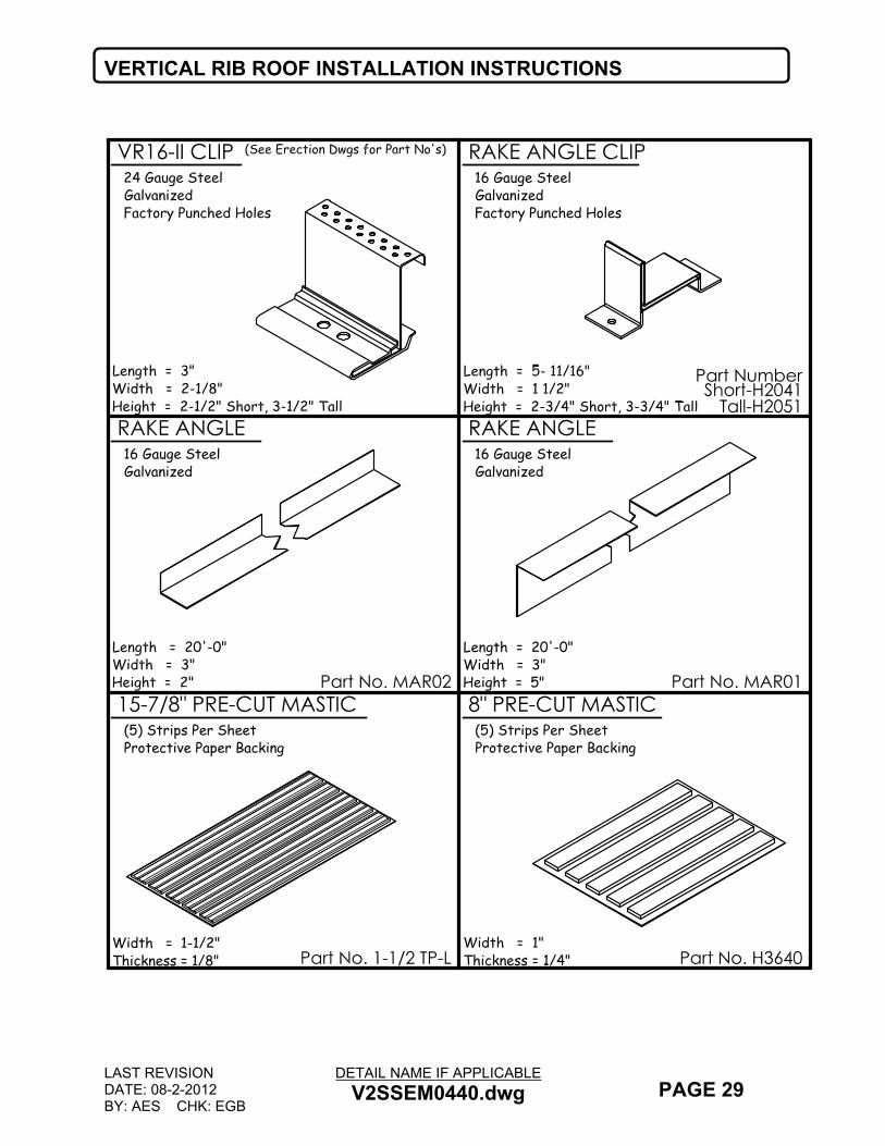
VERTICAL RIB ROOF INSTALLATION INSTRUCTIONS
LAST REVISIONDATE: 08-2-2012BY: AES CHK: EGB
DETAIL NAME IF APPLICABLEV2SSEM0440.dwg PAGE 29
Width = 1-1/2"Thickness = 1/8"
(5) Strips Per SheetProtective Paper Backing
Part Number
16 Gauge SteelGalvanized
RAKE ANGLE
16 Gauge SteelGalvanizedFactory Punched Holes
Short-H2041Tall-H2051
Length = 20'-0"Width = 3"Height = 5"
16 Gauge SteelGalvanized
VR16-II CLIP
8" PRE-CUT MASTIC
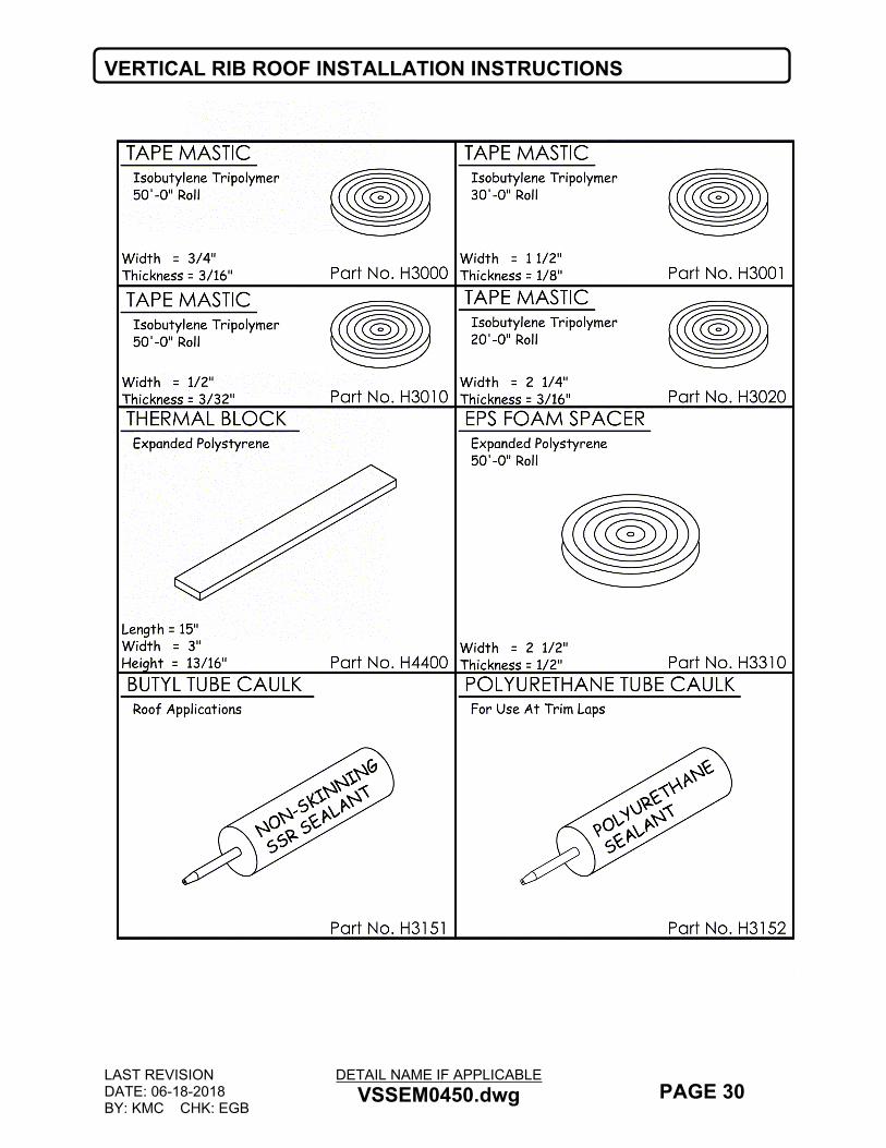
VERTICAL RIB ROOF INSTALLATION INSTRUCTIONS
LAST REVISIONDATE: 06-18-2018BY: KMC CHK: EGB
DETAIL NAME IF APPLICABLEVSSEM0450.dwg PAGE 30

VERTICAL RIB ROOF INSTALLATION INSTRUCTIONS
LAST REVISIONDATE: 4-03-2018BY: SDF CHK: AES
DETAIL NAME IF APPLICABLEV2SSEM0460.dwg PAGE 31
VERTICAL RIB ROOF INSTALLATION INSTRUCTIONS
LAST REVISIONDATE: 8-2-2012BY: AES CHK: EGB
DETAIL NAME IF APPLICABLEV2SSEM0460.dwg PAGE 32
10.0 PREPARATION FOR ROOF PANEL INSTALLATION
10.1 GENERAL
The following details provide graphic illustration of the roof assembly steps. The purpose is to instruct the erector in correct and efficient assembly of the roof system.
Because of the many variations in conditions, it is important that you review the job to identify and isolate the specific installation details required for your job.
Review the erection drawings for differences with these details. If differences exist, the erection drawings will take precedence.
These details are arranged in a step-by-step sequence. Following this sequence ensures that correct assembly and ensures that the part to be worked on will be readily accessible for the next assembly step.
Do not shortcut these assembly steps without careful consideration of the possibility of incorrect or omitted assembly and the resulting corrective rework.
To minimize confusion, the details are always oriented so that the view is from eave to ridge, with the starting rake at the left and finish rake at the right. Refer to the erection drawings to determine the required sheeting direction and rake conditions.
To help ensure weather-tightness, the details emphasize proper fit-up, sealing and fastening. It is most important that only the specified mastics and fasteners be used for each condition and that they be installed correctly as shown on these details and the erection drawings.
Be sure that these critical instructions are reviewed often and the roof assembly is checked at each assembly step.
.

VERTICAL RIB ROOF INSTALLATION INSTRUCTIONS
LAST REVISIONDATE: 09-26-2008BY: KMC CHK: EGB
DETAIL NAME IF APPLICABLESSEM0100.dwg PAGE 33
10.2 ORIENTATION AND EXPLANATION
The details in this section will show the installation of the eave plate, eave mastic, rake clips, rake angle, and the first run of insulation. These are the parts that must be installed before the roof panel installation can begin.
The view below shows the roof system oriented for a left-to-right sheeting direction. For right-to-left sheeting direction, reverse the parts orientation. When panel end laps are required the sheeting direction must be right-to-left (looking up the roof slope). Reference the Final Erection Drawing set to determine the sheeting direction.
The panel erection sequence must always be started from the low eave corner working toward the high eave or ridge. The full panel run from eave to high eave or ridge must be installed before the next panel run can be started.
In the case of a building with a roof step, the lower level panels must be installed before the upper level panels. Install six lower panels ahead of the upper panels.
Rake Angle
Rake Angle
Rake Clips (typ.)
Insulation Starting Run
Purlins
Eave Strut
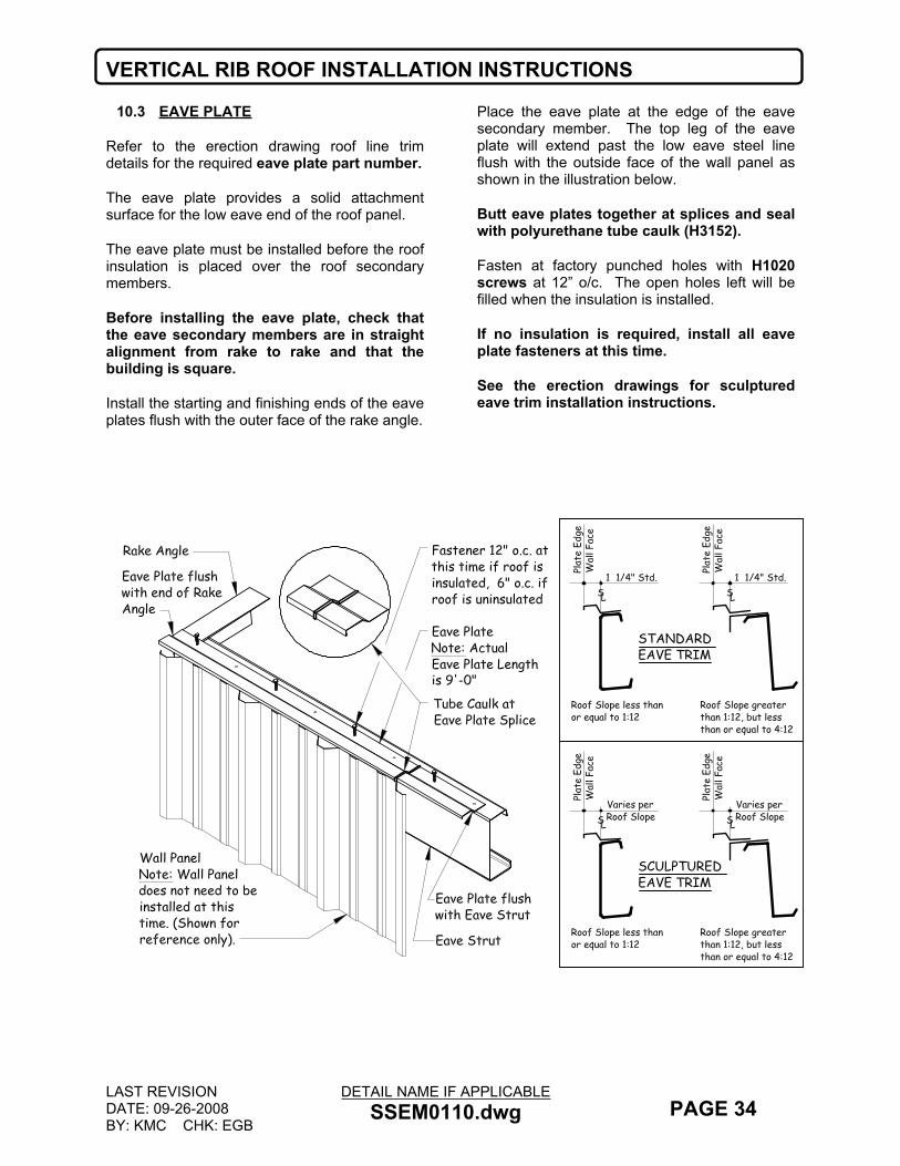
VERTICAL RIB ROOF INSTALLATION INSTRUCTIONS
LAST REVISIONDATE: 09-26-2008BY: KMC CHK: EGB
DETAIL NAME IF APPLICABLESSEM0110.dwg PAGE 34
10.3 EAVE PLATE
Refer to the erection drawing roof line trim details for the required eave plate part number.
The eave plate provides a solid attachment surface for the low eave end of the roof panel.
The eave plate must be installed before the roof insulation is placed over the roof secondary members.
Before installing the eave plate, check that the eave secondary members are in straight alignment from rake to rake and that the building is square.
Install the starting and finishing ends of the eave plates flush with the outer face of the rake angle.
Place the eave plate at the edge of the eave secondary member. The top leg of the eave plate will extend past the low eave steel line flush with the outside face of the wall panel as shown in the illustration below.
Butt eave plates together at splices and seal with polyurethane tube caulk (H3152).
Fasten at factory punched holes with H1020 screws at 12” o/c. The open holes left will be filled when the insulation is installed.
If no insulation is required, install all eave plate fasteners at this time.
See the erection drawings for sculptured eave trim installation instructions.
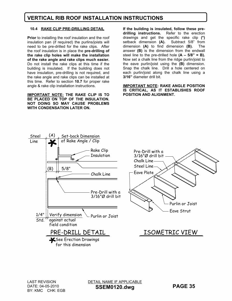
VERTICAL RIB ROOF INSTALLATION INSTRUCTIONS
LAST REVISIONDATE: 04-05-2010BY: KMC CHK: EGB
DETAIL NAME IF APPLICABLESSEM0120.dwg PAGE 35
10.4 RAKE CLIP PRE-DRILLING DETAIL
Prior to installing the roof insulation and the roof insulation pan (if required) the purlins/joists will need to be pre-drilled for the rake clips. After the roof insulation is in place the pre-drilling of the rake clip holes will make the installation of the rake angle and rake clips much easier. Do not install the rake clips at this time if the building is insulated. If the building does not have insulation, pre-drilling is not required, and the rake angle and rake clips can be installed at this time. Refer to section 10.7 for proper rake angle & rake clip installation instructions.
IMPORTANT NOTE: THE RAKE CLIP IS TO BE PLACED ON TOP OF THE INSULATION. NOT DOING SO MAY CAUSE PROBLEMS WITH CONDENSATION LATER ON.
If the building is insulated, follow these pre-drilling instructions. Refer to the erection drawings and get the specific rake clip (*) setback dimension (A). Subtract 5/8” from dimension (A) to find dimension (B). The answer (B) is the dimension from the endwall steel line to the pre-drilled hole (A – 5/8” = B). Now set a chalk line from the ridge purlin/joist to the eave purlin/joist using the (B) dimension. Snap the chalk line. Drill a hole centered on each purlin/joist along the chalk line using a 3/16” diameter drill bit.
IMPORTANT NOTE: RAKE ANGLE POSITION IS CRITICAL, AS IT ESTABLISHES ROOF POSITION AND ALIGNMENT.

VERTICAL RIB ROOF INSTALLATION INSTRUCTIONS
LAST REVISIONDATE: 09-26-2008BY: KMC CHK: EGB
DETAIL NAME IF APPLICABLESSEM0130.dwg PAGE 36
10.5 INSULATION
Install the insulation pan (optional, refer to erection drawing ridge detail to see if your project requires insulation pan) at the ridge prior to any insulation installation.
Insulation pan part numbers: (IPA01) at purlins, (IPB01) at joists.
Align the edge of the insulation with the building steel lines at both the rake and eave.
Pull the insulation toward the ridge/high eave so as to create a smooth appearance of the insulation backing.
Consult the insulation manufacturer for proper seaming and taping methods. At the high side/ridge use (H1020) screws with insulation retainer washers (H2200) at 12” o/c
At the low eave, remove a 4” strip of insulation from the backing leaving a 4” strip of backing exposed. Fold this strip of backing over the insulation batt creating a double vapor barrier.
Fasten the insulation to the lower leg of the eave plate using (H1020) screws and retainer washers (H2200) in the open factory punched eave plate holes. Also fill the void in the eave strut the full length of the building.

VERTICAL RIB ROOF INSTALLATION INSTRUCTIONS
LAST REVISIONDATE: 09-26-2008BY: KMC CHK: EGB
DETAIL NAME IF APPLICABLEVSSEM0140.dwg PAGE 37
10.6 PROPER MASTIC INSTALLATION PROCEDURES
VR16 II panels are shipped with thin plastic film along each shoulder of the panel. Prior to installing any tape mastic this film must be removed.
Apply mastic only to clean, dry surfaces.
Roll mastic out to arm length. Press the mastic firmly in place making sure it is tightly formed to all bends.
Remove paper backing only when ready to install top component.
Splice mastic with a 2” lap. Press lapped pieces of mastic firmly together to form a single thickness.
DO NOT STRETCH MASTIC ACROSS CORNERS. THIS WILL DECREASE THE THICKNESS WHERE IT IS NEEDED THE MOST, AND MAY NOT PERFORM AS DESIGNED.
2"
INCORRECT CORRECT
MASTIC LAP

VERTICAL RIB ROOF INSTALLATION INSTRUCTIONS
LAST REVISIONDATE: 09-26-2008BY: KMC CHK: EGB
DETAIL NAME IF APPLICABLESSEM0145.dwg PAGE 38
10.7 UNDERSTANDING RAKE CLIP AND RAKE ANGLE INSTALLATION
The rake angle slides onto the rake clips as shown in the details below. Because the roof panel is attached to the rake angle, this assembly method allows the rake angle to move with the thermal expansion and contraction of the roof panel.
Also refer to sections 10.8 and 10.9 for more specific rake angle and rake clip assembly instructions.

VERTICAL RIB ROOF INSTALLATION INSTRUCTIONS
LAST REVISIONDATE: 10-09-2018BY: EGB CHK: KMC
DETAIL NAME IF APPLICABLE- PAGE 39
10.8 RAKE CLIP AND RAKE ANGLE INSTALLATION
SETTING OF RAKE ANGLE POSTION IS CRITICAL, AS IT WILL ESTABLISH ROOF POSITION AND ALIGNMENT.Slide the rake clips on to the rake angle (MAR02) prior to installing the angle. This assembly method allows the rake angle to move with the thermal expansion and contraction of the roof panel.
Rake clip part numbers: (H2041) at short clips, (H2051) at tall clips. Refer to the erection drawing details for your projects’ clip type.
Prior to installing the rake angle, apply a continuous run of 1 1/2” mastic (H3001) the full length of the top leg of the eave plate. NOTE: The mastic must be held flush with the outside end of the eave plate (see below). Do not remove the paper backing until the panels are installed, and then remove only enough for each panel run. This will help the mastic from becoming contaminated. (SEE DETAIL ON NEXT PAGE)
Before placing the rake angle on the mastic, extend the angle to the proper (**) overhang dimension (refer to the low eave details on the erection drawings for this dimension). NOTE: At a sculptured eave condition, the rake angle stops flush with the edge of the eave plate.
Place the rake clips and the angle over the insulation and eave plate.Use a small drift pin to locate the pre-drilled clip hole. While holding the rake clip in place with the drift pin, fasten the clip in the opposite clip hole with (1) fastener: (H1020) at purlins, (H1070) at joists. Remove the drift pin and fasten with the same type fastener in the remaining clip hole as described in the previous step. (NOTE: (2) SCREWS ARE REQUIRED AT EVERY CLIP LOCATION). Do not cut the insulation around the clip locations.If the building does not have insulation, then align the rake angle clip hole with the snapped chalk line and fasten with (2) screws per clip: (H1020) at purlins, (H1070) at joists.
Rake angles are to be spliced with a minimum 2” lap. Fasten lap with (1) fastener (H1020). Keep the rake angle laps a minimum of 2” away from any rake any clip. The rake angle must not be fastened into the rake angle clip, as this will not allow the roof to expand and contract properly.After rake angle is secured, place a small piece of 1 ½” mastic (H3001) on top of rake as shown below.
(SEE DETAIL ON NEXT PAGE)
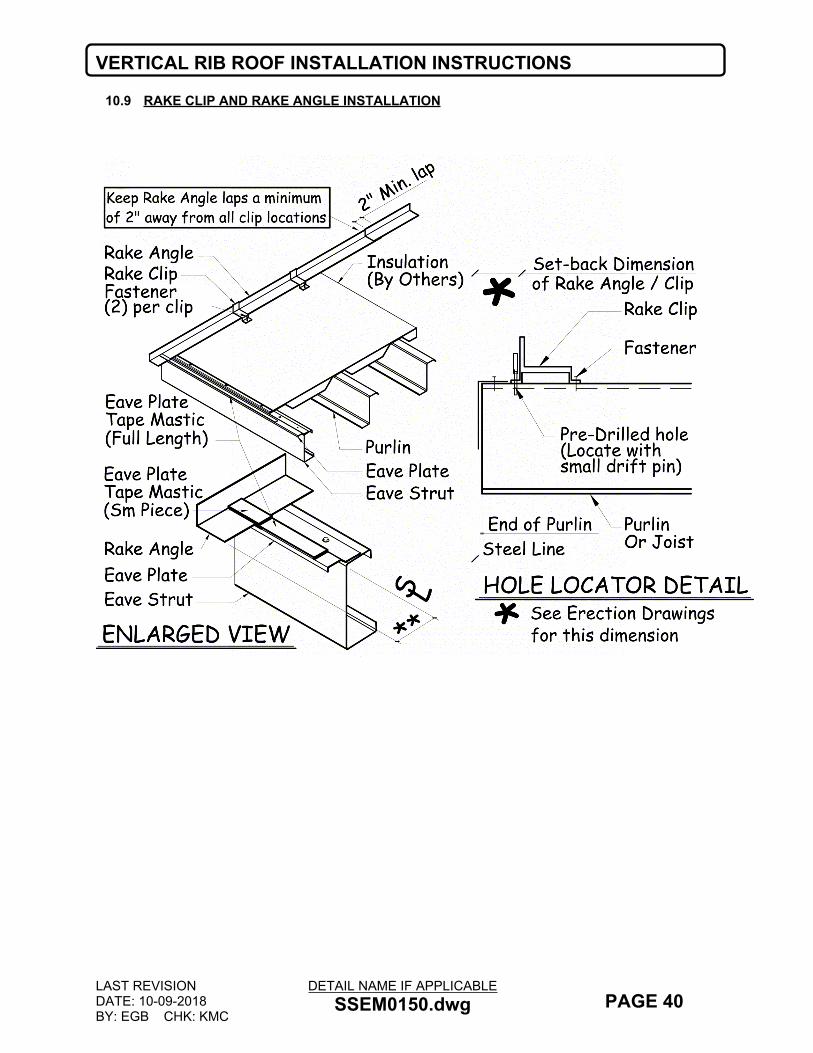
VERTICAL RIB ROOF INSTALLATION INSTRUCTIONS
LAST REVISIONDATE: 10-09-2018BY: EGB CHK: KMC
DETAIL NAME IF APPLICABLESSEM0150.dwg PAGE 40
10.9 RAKE CLIP AND RAKE ANGLE INSTALLATION

VERTICAL RIB ROOF INSTALLATION INSTRUCTIONS
LAST REVISIONDATE: 10-09-2018BY: EGB CHK: KMC
DETAIL NAME IF APPLICABLESSEM0190.dwg PAGE 41
10.10 THERMAL BLOCKS
Thermal blocks are used only with tall panel clips.Position the thermal block (H4400) on top of the insulation over each purlin line before installing the roof panels.Place the thermal block tight against the rake angle and the next panel clip. Thereafter, the blocks will be placed between panel clips.
10.11 EPS FOAM SPACEREPS Foam Spacer is used only with short panel clips on buildings without insulation.EPS Foam Spacer (H3310) is provided in 50’ rolls and is placed on top of the purlin leg before installing the panel clips.EPS Foam Spacer has an adhesive backing. Remove the protective paper before rolling it out.
In the absence of insulation, the EPS Foam Spacer will reduce noise and vibration caused by the wind. It may also help reduce damage caused by metal to metal contact.
10.12 FINAL PRE-PANEL INSTALLATION DETAIL
The following detail is a summary of all of the “Preparation for Roof Panel Installation” steps. Make sure that all the necessary steps have been taken and have been properly followed.Before installing any roof panels, refer to the erection drawing roof sheeting plan and roof details to see if there are any other special requirements.At this time, make sure that the eave plate is fastened to the eave member at 6” o/c with (H1020) screws.Install a string line from the end of the rake angle to the next frame line. This will help keep the ends of the roof panels in line
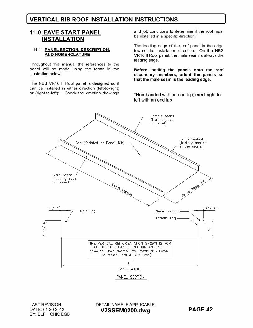
VERTICAL RIB ROOF INSTALLATION INSTRUCTIONS
LAST REVISIONDATE: 01-20-2012BY: DLF CHK: EGB
DETAIL NAME IF APPLICABLEV2SSEM0200.dwg PAGE 42
11.0 EAVE START PANEL INSTALLATION
11.1 PANEL SECTION, DESCRIPTION, AND NOMENCLATURE
Throughout this manual the references to the panel will be made using the terms in the illustration below.
The NBS VR16 II Roof panel is designed so it can be installed in either direction (left-to-right) or (right-to-left)*. Check the erection drawings
and job conditions to determine if the roof must be installed in a specific direction.
The leading edge of the roof panel is the edge toward the installation direction. On the NBS VR16 II Roof panel, the male seam is always the leading edge.
Before loading the panels onto the roof secondary members, orient the panels so that the male seam is the leading edge.
*Non-handed with no end lap, erect right to left with an end lap
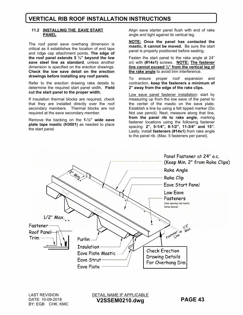
VERTICAL RIB ROOF INSTALLATION INSTRUCTIONS
LAST REVISIONDATE: 10-09-2018BY: EGB CHK: KMC
DETAIL NAME IF APPLICABLEV2SSEM0210.dwg PAGE 43
11.2 INSTALLING THE EAVE START PANEL
The roof panel eave overhang dimension is critical as it establishes the location of end laps and ridge cap attachment points. The edge of the roof panel extends 5 ¼” beyond the low eave steel line as standard, unless another dimension is specified on the erection drawings. Check the low eave detail on the erection drawings before installing any roof panels.Refer to the erection drawing rake details to determine the required start panel width. Field cut the start panel to the proper width. If insulation thermal blocks are required, check that they are installed directly over the roof secondary members. Thermal blocks are not required at the eave secondary member.
Remove the backing on the 1-½” wide eave plate tape mastic (H3001) as needed to place the start panel.
Align eave starter panel flush with end of rake angle and tight against its vertical leg.
NOTE: Once the panel has contacted the mastic, it cannot be moved. Be sure the start panel is properly positioned before seating.
Fasten the start panel to the rake angle at 24” o/c with (#14x1) screws. NOTE: The fastener line cannot exceed ½” from the vertical leg of the rake angle to avoid trim interference.
To ensure proper roof expansion and contraction, keep the fasteners a minimum of 2” away from the edge of the rake clips.Low eave panel fastener installation: start by measuring up from the low eave of the panel to the center of the mastic on the eave plate. Establish a line by using a felt tipped marker (Do Not use pencil). Next, measure along that line, from the panel rib to rake angle, marking fastener locations using the following fastener spacing: 2”, 5-1/4”, 8-1/2”, 11-3/4” and 15”. Lastly, install fasteners (#14x1) from rake angle to the panel rib. (Max. 5 fasteners per panel).

VERTICAL RIB ROOF INSTALLATION INSTRUCTIONS
LAST REVISIONDATE: 10-09-2018BY: EGB CHK: KMC
DETAIL NAME IF APPLICABLEV2SSEM0230.dwg PAGE 44
11.3 INSTALLING THE LEADING EDGE PANEL CLIPS
Install roof panel clips to the leading edge of the roof panel, at each roof secondary structural member. NOTE: Panel clips are not required at the eave.
Roof panel clip types (refer to the erection drawing details for your projects’ clip type):
SHORT SLIDING (LSEC-1) TALL SLIDING (LSEC-2T)
To install the clips, tilt the clip so that the tab can be hooked over the edge of the roof panel male seam, then rotate the clip down into the vertical position. Position the clip base so that the clip
fasteners can be installed through the holes in the base and into the roof secondary member.
When fiberglass insulation is used, the panel clips sit on top of the insulation and the insulation is compressed between the clip base and top of the roof secondary member. In all cases, determine required insulation assembly and the relationship of the panel clips to the insulation.
Specific panel clip details are shown on the following page.
Do not over-drive screws. Over-driving can strip the threads and/or damage the sealing washer. Use screw gun with torque control set to function properly for the combination of fastener size, hole size and material thickness.

VERTICAL RIB ROOF INSTALLATION INSTRUCTIONS
LAST REVISIONDATE: 05-02-2016BY: SDF CHK: KMC
DETAIL NAME IF APPLICABLEV2SSEM0240.dwg PAGE 45
11.4 TYPICAL PANEL CLIP ATTACHMENT DETAILS
Panel clips are available as sliding clips and are available in either tall or short heights. Refer to the erection drawings to determine the type of clip required for each roof condition.
Check that the panel clip tab is seated tightly next to the roof panel seam and that the panel clip hook has captured the panel lip
Check that the clip tab is vertical and that the clip base is set square and firmly over the roof secondary member.
Panel clips always require two fasteners per clip. Use (#12 x 1 1/4” SDHH) at purlins, use (#12 x 1 1/2” SDHHT5) at joists. (At lapped or nested purlins, pre-drilling may be required).
Check that the clip fasteners are equally spaced through the clip base holes and are securely engaged into the roof secondary member. Tighten screws in the clip to allow the lower part of the clip to disengage the self-centering tab located on the upper part of the clip.
Do not over-drive screws. Over-driving can strip the threads and/or damage the sealing washer. Use screw gun with torque control set to function properly for the combination of fastener size, hole size and material thickness.

VERTICAL RIB ROOF INSTALLATION INSTRUCTIONS
LAST REVISIONDATE: 10-09-2018BY: EGB CHK: KMC
DETAIL NAME IF APPLICABLEV2SSEM0250.dwg PAGE 46
11.5 INSTALLATION OF THE LAP STIFFENER AT THE EAVE START PANEL
Before installing the lap stiffener, make sure that the panel overhang dimension at the up-slope end of the install panel is correct. Refer to the detail below and the erection drawing details.
At the start panel, a lap stiffener (LSLS-1) must be field cut to the proper width. To determine this width, measure the flat of the start panel and subtract 3”. The lap stiffener should fit
tight up against the horizontal leg of the rake angle.
Slide the lap stiffener onto the end of the start panel. If there are no tabs left on the lap stiffener after field cutting to width, drill and fasten with (2) pop rivets (H1100).
IF YOUR BUILDING REQUIRES MORE THAN ONE PANEL TO REACH THE HIGH EAVE OR RIDGE, STOP AND TURN TO THE NEXT PAGE.
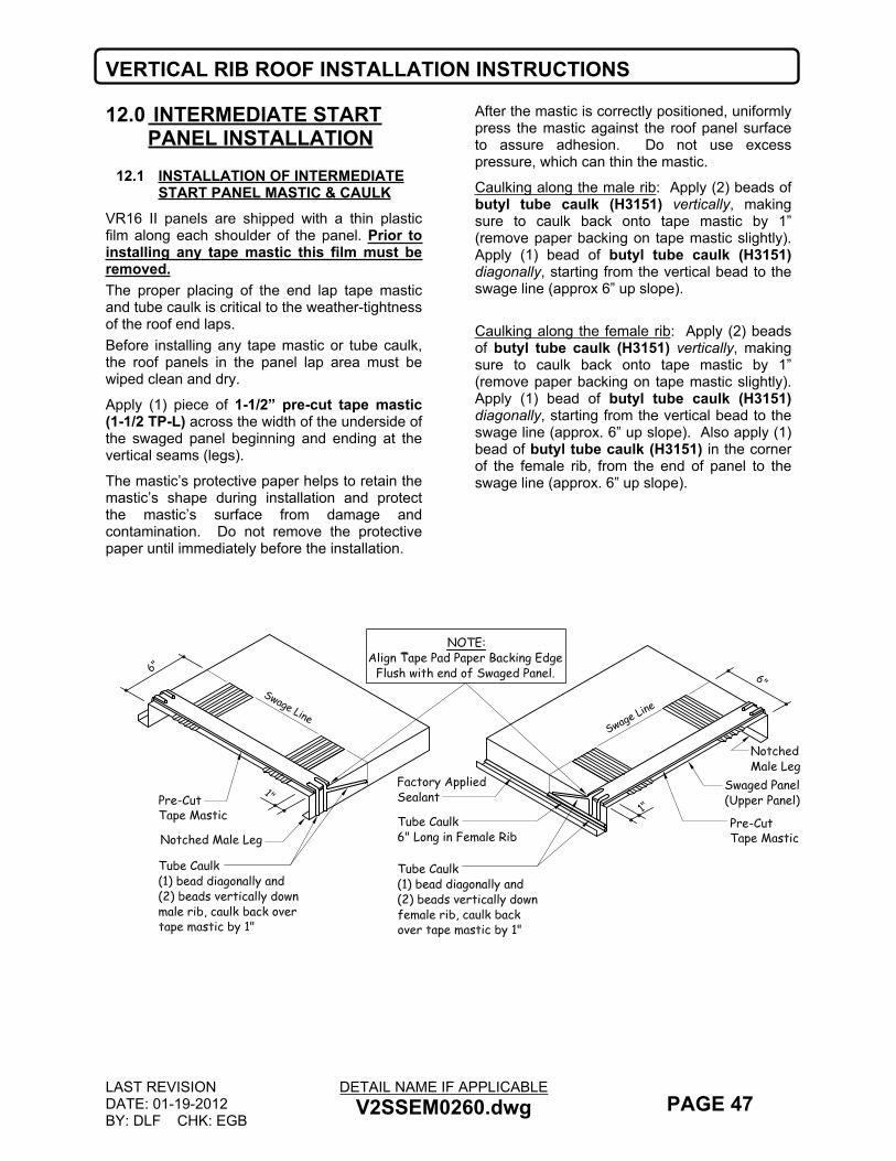
VERTICAL RIB ROOF INSTALLATION INSTRUCTIONS
LAST REVISIONDATE: 01-19-2012BY: DLF CHK: EGB
DETAIL NAME IF APPLICABLEV2SSEM0260.dwg PAGE 47
12.0 INTERMEDIATE START PANEL INSTALLATION
12.1 INSTALLATION OF INTERMEDIATE START PANEL MASTIC & CAULK
VR16 II panels are shipped with a thin plastic film along each shoulder of the panel. Prior to installing any tape mastic this film must be removed.The proper placing of the end lap tape mastic and tube caulk is critical to the weather-tightness of the roof end laps.Before installing any tape mastic or tube caulk, the roof panels in the panel lap area must be wiped clean and dry.
Apply (1) piece of 1-1/2” pre-cut tape mastic (1-1/2 TP-L) across the width of the underside of the swaged panel beginning and ending at the vertical seams (legs).
The mastic’s protective paper helps to retain the mastic’s shape during installation and protect the mastic’s surface from damage and contamination. Do not remove the protective paper until immediately before the installation.
After the mastic is correctly positioned, uniformly press the mastic against the roof panel surface to assure adhesion. Do not use excess pressure, which can thin the mastic.
Caulking along the male rib: Apply (2) beads of butyl tube caulk (H3151) vertically, making sure to caulk back onto tape mastic by 1” (remove paper backing on tape mastic slightly). Apply (1) bead of butyl tube caulk (H3151) diagonally, starting from the vertical bead to the swage line (approx 6” up slope).
Caulking along the female rib: Apply (2) beads of butyl tube caulk (H3151) vertically, making sure to caulk back onto tape mastic by 1” (remove paper backing on tape mastic slightly). Apply (1) bead of butyl tube caulk (H3151) diagonally, starting from the vertical bead to the swage line (approx. 6” up slope). Also apply (1) bead of butyl tube caulk (H3151) in the corner of the female rib, from the end of panel to the swage line (approx. 6” up slope).
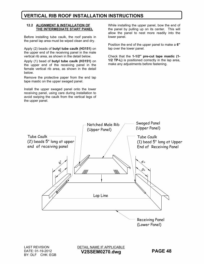
VERTICAL RIB ROOF INSTALLATION INSTRUCTIONS
LAST REVISIONDATE: 01-19-2012BY: DLF CHK: EGB
DETAIL NAME IF APPLICABLEV2SSEM0270.dwg PAGE 48
12.2 ALIGNMENT & INSTALLATION OF THE INTERMEDIATE START PANEL
Before installing tube caulk, the roof panels in the panel lap area must be wiped clean and dry.
Apply (2) beads of butyl tube caulk (H3151) on the upper end of the receiving panel in the male vertical rib area, as shown in the detail below.Apply (1) bead of butyl tube caulk (H3151) on the upper end of the receiving panel in the female vertical rib area, as shown in the detail below.Remove the protective paper from the end lap tape mastic on the upper swaged panel.
Install the upper swaged panel onto the lower receiving panel, using care during installation to avoid swiping the caulk from the vertical legs of the upper panel.
While installing the upper panel, bow the end of the panel by pulling up on its center. This will allow the panel to nest more readily into the lower panel.
Position the end of the upper panel to make a 6” lap over the lower panel.
Check that the 1-1/2” pre-cut tape mastic (1-1/2 TP-L) is positioned correctly in the lap area, make any adjustments before fastening.
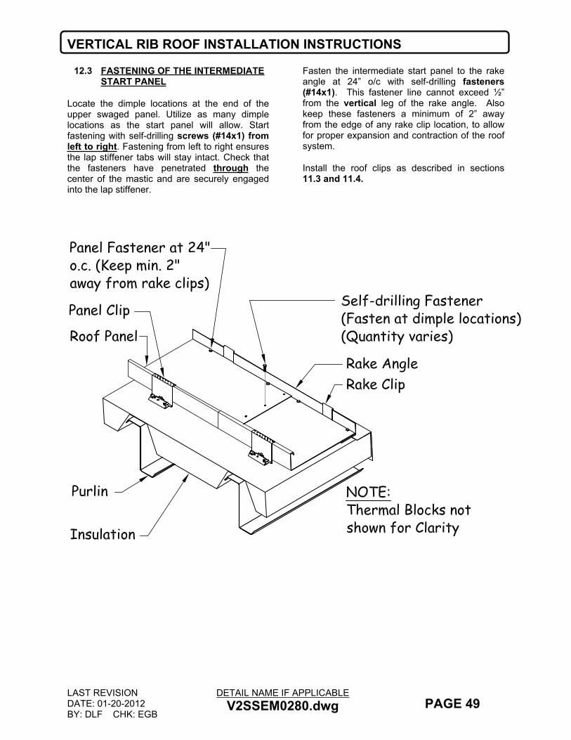
VERTICAL RIB ROOF INSTALLATION INSTRUCTIONS
LAST REVISIONDATE: 01-20-2012BY: DLF CHK: EGB
DETAIL NAME IF APPLICABLEV2SSEM0280.dwg PAGE 49
12.3 FASTENING OF THE INTERMEDIATE START PANEL
Locate the dimple locations at the end of the upper swaged panel. Utilize as many dimple locations as the start panel will allow. Start fastening with self-drilling screws (#14x1) from left to right. Fastening from left to right ensures the lap stiffener tabs will stay intact. Check that the fasteners have penetrated through the center of the mastic and are securely engaged into the lap stiffener.
Fasten the intermediate start panel to the rake angle at 24” o/c with self-drilling fasteners (#14x1). This fastener line cannot exceed ½” from the vertical leg of the rake angle. Also keep these fasteners a minimum of 2” away from the edge of any rake clip location, to allow for proper expansion and contraction of the roof system.
Install the roof clips as described in sections 11.3 and 11.4.

VERTICAL RIB ROOF INSTALLATION INSTRUCTIONS
LAST REVISIONDATE: 09-10-2019BY: KMC CHK: EGB
DETAIL NAME IF APPLICABLEV2SSEM0300.dwg PAGE 50
12.4 EAVE INSTALLATION
Apply a 3” long tape pad (3 TP) on the male vertical leg, making sure the tape pad covers the horizontal leg on the male rib.
Next apply a bead of butyl tube caulk (H3151) along the male horizontal leg, making sure to start at the end of the panel and caulk a distance of 6” for all eave conditions.
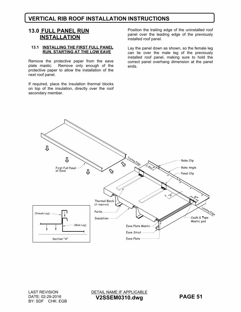
VERTICAL RIB ROOF INSTALLATION INSTRUCTIONS
LAST REVISIONDATE: 02-29-2016BY: SDF CHK: EGB
DETAIL NAME IF APPLICABLEV2SSEM0310.dwg PAGE 51
13.0 FULL PANEL RUN INSTALLATION
13.1 INSTALLING THE FIRST FULL PANEL RUN, STARTING AT THE LOW EAVE
Remove the protective paper from the eave plate mastic. Remove only enough of the protective paper to allow the installation of the next roof panel.
If required, place the insulation thermal blocks on top of the insulation, directly over the roof secondary member.
Position the trailing edge of the uninstalled roof panel over the leading edge of the previously installed roof panel.
Lay the panel down as shown, so the female leg can lie over the male leg of the previously installed roof panel, making sure to hold the correct panel overhang dimension at the panel ends.
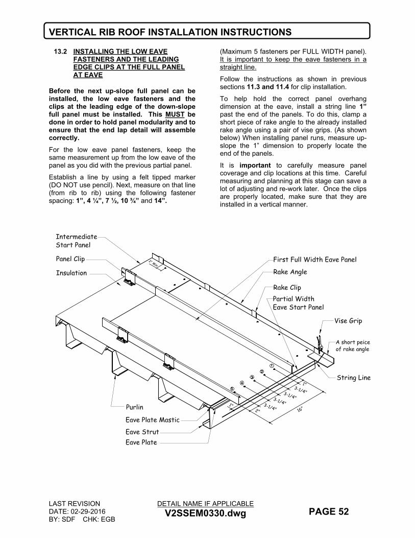
VERTICAL RIB ROOF INSTALLATION INSTRUCTIONS
LAST REVISIONDATE: 02-29-2016BY: SDF CHK: EGB
DETAIL NAME IF APPLICABLEV2SSEM0330.dwg PAGE 52
13.2 INSTALLING THE LOW EAVE FASTENERS AND THE LEADING EDGE CLIPS AT THE FULL PANEL AT EAVE
Before the next up-slope full panel can be installed, the low eave fasteners and the clips at the leading edge of the down-slope full panel must be installed. This MUST be done in order to hold panel modularity and to ensure that the end lap detail will assemble correctly.For the low eave panel fasteners, keep the same measurement up from the low eave of the panel as you did with the previous partial panel.
Establish a line by using a felt tipped marker (DO NOT use pencil). Next, measure on that line (from rib to rib) using the following fastener spacing: 1”, 4 ¼”, 7 ½, 10 ¾” and 14”.
(Maximum 5 fasteners per FULL WIDTH panel). It is important to keep the eave fasteners in a straight line.
Follow the instructions as shown in previous sections 11.3 and 11.4 for clip installation.
To help hold the correct panel overhang dimension at the eave, install a string line 1” past the end of the panels. To do this, clamp a short piece of rake angle to the already installed rake angle using a pair of vise grips. (As shown below) When installing panel runs, measure up-slope the 1” dimension to properly locate the end of the panels.
It is important to carefully measure panel coverage and clip locations at this time. Careful measuring and planning at this stage can save a lot of adjusting and re-work later. Once the clips are properly located, make sure that they are installed in a vertical manner.
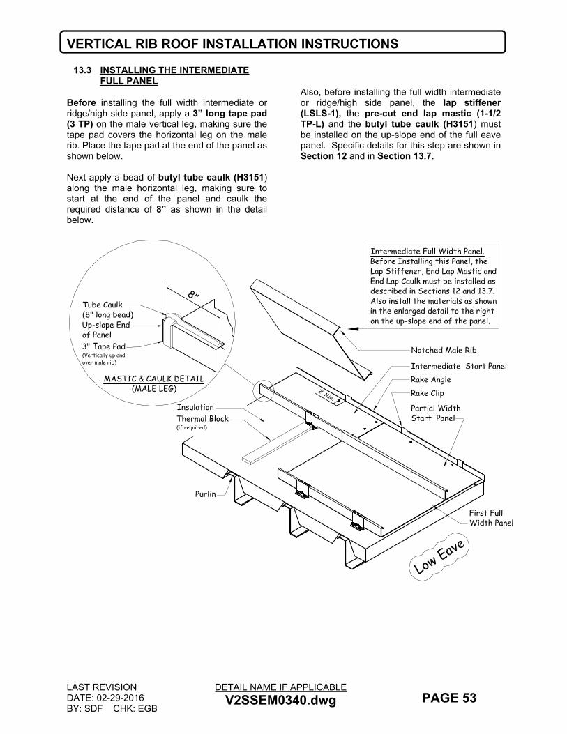
VERTICAL RIB ROOF INSTALLATION INSTRUCTIONS
LAST REVISIONDATE: 02-29-2016BY: SDF CHK: EGB
DETAIL NAME IF APPLICABLEV2SSEM0340.dwg PAGE 53
13.3 INSTALLING THE INTERMEDIATE FULL PANEL
Before installing the full width intermediate or ridge/high side panel, apply a 3” long tape pad (3 TP) on the male vertical leg, making sure the tape pad covers the horizontal leg on the male rib. Place the tape pad at the end of the panel as shown below.
Next apply a bead of butyl tube caulk (H3151) along the male horizontal leg, making sure to start at the end of the panel and caulk the required distance of 8” as shown in the detail below.
Also, before installing the full width intermediate or ridge/high side panel, the lap stiffener (LSLS-1), the pre-cut end lap mastic (1-1/2 TP-L) and the butyl tube caulk (H3151) must be installed on the up-slope end of the full eave panel. Specific details for this step are shown in Section 12 and in Section 13.7.
First FullWidth Panel

VERTICAL RIB ROOF INSTALLATION INSTRUCTIONS
LAST REVISIONDATE: 04-24-2013BY: DLF CHK: EGB
DETAIL NAME IF APPLICABLEVSSEM0325.dwg PAGE 54
13.4 PANEL MODULARITY
Maintaining panel modularity is EXTREMELY IMPORTANT, as the panels may shrink or grow during installation.
Use rib clamps at the low eave, endlap and the ridge/high eave during roof panel installation.
Rib clamps can be purchased from your closest NBS plant, part # H7300.
Check the panel modularity every four to five panel runs by measuring from a fixed plumb line (possibly the endwall steel line) over the completed panel runs.
It is also important to hand crimp (with the manual hand crimper/seamer tool) all panel clips locations, only after an entire full length panel run is installed.
Rib Clamp(Typ.)

VERTICAL RIB ROOF INSTALLATION INSTRUCTIONS
LAST REVISIONDATE: 01-23-2012BY: DLF CHK: EGB
DETAIL NAME IF APPLICABLEVSSEM0325A.dwg PAGE 55
13.5 PANEL MODULARITY MEASUREMENTS
Maintaining panel modularity is EXTREMELY IMPORTANT, as the panels may shrink or grow during installation.
Check the panel modularity every four to five panel runs by measuring from a fixed plumb line (possibly the endwall steel line) over the completed panel runs.
Measurements should be taken at the ridge/high eave, at end laps, at the low eave, and at random clip locations on long panel runs. The dimensions at these locations (as well as any other point along the panel run) should be the same.
13.6 ADJUSTING PANEL MODULARITY
Eave fastener placement is critical, as this helps control proper panel modularity.
Modularity can be adjusted at each purlin line by slightly tilting the panel clip. However, DO NOT ADJUST THE PANEL WIDTH BY MORE THAN 1/8” ON ANY PANEL AREA.Adjustments may be required to several panels to get back on proper module. These adjustments should be made at the low eave and ridge/high eave to match the end lap.
MeasuringTape at Eave
Low Eave
High Eave
Measuring Tape atRidge
Read measurementat face of panelseam
Hold or Clamp End ofTape Tight againest Faceof Panel Seam

VERTICAL RIB ROOF INSTALLATION INSTRUCTIONS
LAST REVISIONDATE: 01-23-2012BY: DLF CHK: EGB
DETAIL NAME IF APPLICABLEV2SSEM0345.dwg PAGE 56
13.7 END LAP ASSEMBLY DETAIL AT FULL PANEL
VR16 II panels are shipped with a thin plastic film along each shoulder of the panel. Prior to installing any tape mastic this film must be removed.Before installing the any tape mastic or tube caulk, the roof panels in the panel lap area must be wiped clean and dry.Slide the lap stiffener (LSLS-1) on to the lower panel.
Reference details and instructions in Sections 12.1 and 12.2 for upper roof panel prep.Fasten the upper panel with (5) self-drilling fasteners (#14x1) in the sequence shown, following the additional instructions in the detail below.
16"
3-1/4"
1"
1
Panel Clip
Lap Stiffener
Swaged Panel(Upper Panel)
Receiving Panel(Lower Panel)
Dimple
(5) Fastenersper panel flat
Fastener Sequence
2
3
4
5
3-1/4"3-1/4"3-1/4"2" 1"
Dimples
Notched Male Rib

VERTICAL RIB ROOF INSTALLATION INSTRUCTIONS
LAST REVISIONDATE: 09-01-2009BY: EGB CHK: KMC
DETAIL NAME IF APPLICABLEV2SSEM0370.dwg PAGE 57
13.8 ZEE CLOSURE INSTALLATIONAfter several VR16 II panels have been installed, need to start installing full pieces of the Zee Closure (TRCZ). Installing the Zee Closure helps maintain panel modularity. Temporarily clamping of the vertical seam panel will insure mastic engagement and to maintain modularity until the fasteners are installed. Start the first full Zee piece in the middle of the first full panel run. The termination Zee Closure installation is covered in sections: 16.9, 16.10 & 16.14.Place a continuous piece of 2 ¼” tape mastic (H3020) on the bottom leg of the Zee Closure (TRCZ). If building has a painted roof, need to install a roof colored Zee Closure Cover Flash (TL1) over each Zee Closure (TRCZ). After the tape mastic has been placed onto the Zee Closure, apply two beads of Butyl Tube Caulk (H3151) to the Zee Closure Cover Flash (TL1) as shown in the detail below. Next peel the paper backing off the tape mastic and place the Zee Closure (with the Zee Closure
Cover) under the panel and on the ends of the panels. Fasten with (5) #14x1” roof fasteners per full panel using the fastener sequence below.
Zee Closure Lap Instructions:
On the lapped Zee Closure, start the 2 1/4” tape mastic (H3020) 2” from the end as shown. Next apply Butyl Tube Caulk (H3151) around each surface of the Zee piece as shown in the detail below. Place over the back of the previous installed Zee Closure and repeat the installation and attachment as covered in the previous steps above. Add (1) #14x1” fastener into the lapped Zee’s.Move roof clamps (H7300) along as panel erection and Zee Closure installation allows.After all of the Zee Closure have been installed, run a continuous strip of ¾” tape mastic (H3000) along the top of the Zee Closure as shown. Leave the paper backing intact until you are ready to install the ridge cap or high side trim.
*
SECTION "A"
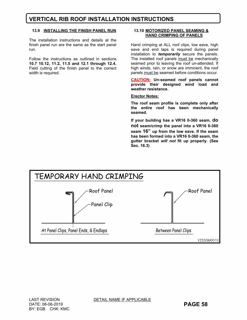
VERTICAL RIB ROOF INSTALLATION INSTRUCTIONS
LAST REVISIONDATE: 08-06-2019BY: EGB CHK: KMC
DETAIL NAME IF APPLICABLEPAGE 58
13.9 INSTALLING THE FINISH PANEL RUN
The installation instructions and details at the finish panel run are the same as the start panel run.
Follow the instructions as outlined in sections 10.7 10.12, 11.2, 11.5 and 12.1 through 12.4. Field cutting of the finish panel to the correct width is required.
13.10 MOTORIZED PANEL SEAMING & HAND CRIMPING OF PANELS
Hand crimping at ALL roof clips, low eave, high eave and end laps is required during panel installation to temporarily secure the panels. The installed roof panels must be mechanically seamed prior to leaving the roof un-attended. If high winds, rain, or snow are imminent, the roof panels must be seamed before conditions occur.
CAUTION: Un-seamed roof panels cannot provide their designed wind load and weather resistance.Erector Notes: The roof seam profile is complete only after the entire roof has been mechanically seamed.
If your building has a VR16 II-360 seam, do not seam/crimp the panel into a VR16 II-360 seam 16” up from the low eave. If the seam has been formed into a VR16 II-360 seam, the gutter bracket will not fit up properly. (See Sec. 16.3)
Panel Clip
Roof Panel
TEMPORARY HAND CRIMPING
Roof Panel

VERTICAL RIB ROOF INSTALLATION INSTRUCTIONS
LAST REVISIONDATE: 09-26-2008BY: EGB CHK: KMC
DETAIL NAME IF APPLICABLEPAGE 59
14.0PREPARATION FOR ROOF LINE TRIM INSTALLATON
14.1 PREPARATION FOR TRIM INSTALLATON
BEFORE PROCEEDING WITH THE ROOF LINE TRIM INSTALLATION, WALK THE ROOF PAYING PARTICULAR ATTENTION TO THE FOLLOWING AREAS:
All panel splices are straight, and are properly installed.
All ridge closure zees are in place and properly fastened.
All metal shavings and debris have been removed from the roof.
All perimeter fasteners are in place and properly tightened. The rubber washer should be visible all around the fastener.
14.2 GENERAL
Begin installing trim at the back of the building working toward the front. This will “hide” the trim laps from direct view.
When lapping rake trim and rake parapet trim, the upper piece should overlap the lower piece. This will help prevent water from entering into the building through the lap.
Gutter/Rake trim (bird stop) must be installed prior to the installation of the low eave trim. See section 16 for proper installation details.
Some field cutting, trimming, and bending is required. Extreme care must be taken while performing any fieldwork so as to produce an attractive, weather-tight condition.
Refer to you project erection drawings and the following pages for trim part numbers.
NOTE: Polyurethane tube caulk (H3152) is used at all trim laps except at the ridge cap. The ridge cap utilizes the butyl tube caulk (H3151). It is important that the correct caulk be used. Careful attention to the details is a must.
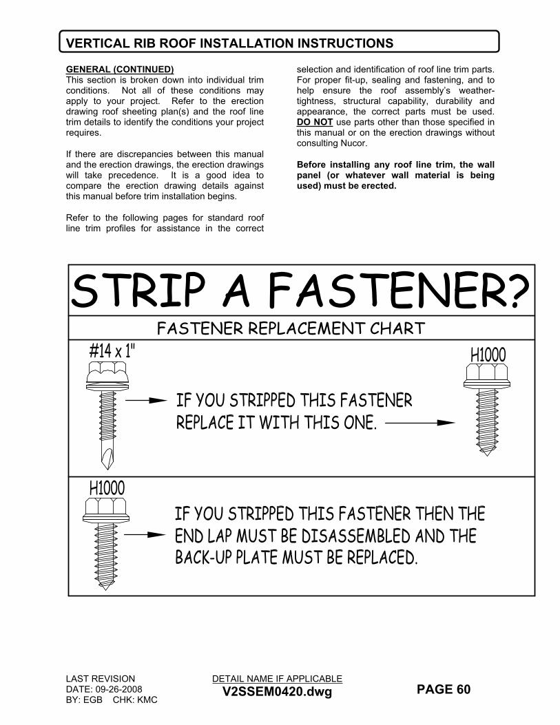
VERTICAL RIB ROOF INSTALLATION INSTRUCTIONS
LAST REVISIONDATE: 09-26-2008BY: EGB CHK: KMC
DETAIL NAME IF APPLICABLEV2SSEM0420.dwg PAGE 60
GENERAL (CONTINUED)This section is broken down into individual trim conditions. Not all of these conditions may apply to your project. Refer to the erection drawing roof sheeting plan(s) and the roof line trim details to identify the conditions your project requires.
If there are discrepancies between this manual and the erection drawings, the erection drawings will take precedence. It is a good idea to compare the erection drawing details against this manual before trim installation begins.
Refer to the following pages for standard roof line trim profiles for assistance in the correct
selection and identification of roof line trim parts. For proper fit-up, sealing and fastening, and to help ensure the roof assembly’s weather-tightness, structural capability, durability and appearance, the correct parts must be used. DO NOT use parts other than those specified in this manual or on the erection drawings without consulting Nucor.
Before installing any roof line trim, the wall panel (or whatever wall material is being used) must be erected.
FASTENER REPLACEMENT CHARTSTRIP A FASTENER?

VERTICAL RIB ROOF INSTALLATION INSTRUCTIONS
LAST REVISIONDATE: 09-26-2008BY: EGB CHK: KMC
DETAIL NAME IF APPLICABLEV2SSEM0470.dwg PAGE 61
15.0 STANDARD ROOF LINE TRIM PARTS15.1 GENERALThis section is intended to show you diagrams of the trim parts that are used in this section of the manual. These parts cover the standard conditions. The erection drawing details will cover the special conditions.
It is a good idea to check the erection drawing details against the details in this section. If there are discrepancies, the erection drawings will take precedence.

VERTICAL RIB ROOF INSTALLATION INSTRUCTIONS
LAST REVISIONDATE: 09-26-2008BY: EGB CHK: KMC
DETAIL NAME IF APPLICABLESSEM0480.dwg PAGE 62
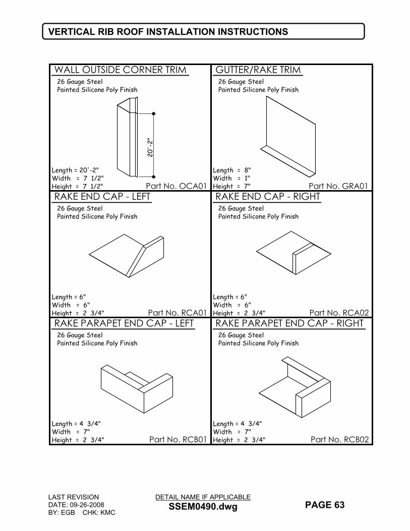
VERTICAL RIB ROOF INSTALLATION INSTRUCTIONS
LAST REVISIONDATE: 09-26-2008BY: EGB CHK: KMC
DETAIL NAME IF APPLICABLESSEM0490.dwg PAGE 63

VERTICAL RIB ROOF INSTALLATION INSTRUCTIONS
LAST REVISIONDATE: 07-27-2017BY: EGB CHK: KMC
DETAIL NAME IF APPLICABLESSEM0500A.dwg PAGE 64
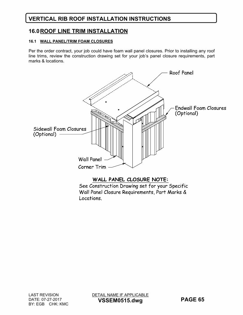
VERTICAL RIB ROOF INSTALLATION INSTRUCTIONS
LAST REVISIONDATE: 07-27-2017BY: EGB CHK: KMC
DETAIL NAME IF APPLICABLEVSSEM0515.dwg PAGE 65
16.0ROOF LINE TRIM INSTALLATION16.1 WALL PANEL/TRIM FOAM CLOSURES
Per the order contract, your job could have foam wall panel closures. Prior to installing any roof line trims, review the construction drawing set for your job’s panel closure requirements, part marks & locations.
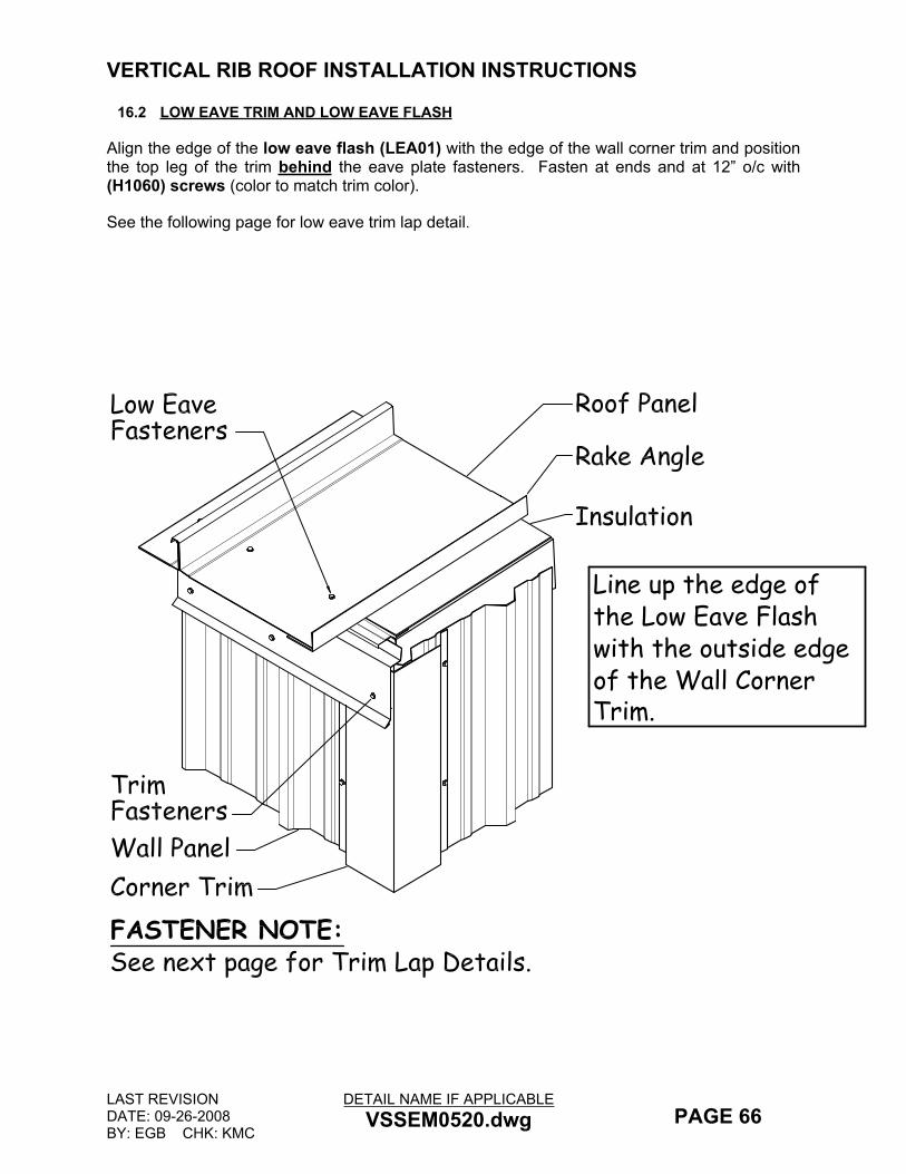
VERTICAL RIB ROOF INSTALLATION INSTRUCTIONS
LAST REVISIONDATE: 09-26-2008BY: EGB CHK: KMC
DETAIL NAME IF APPLICABLEVSSEM0520.dwg PAGE 66
16.2 LOW EAVE TRIM AND LOW EAVE FLASH
Align the edge of the low eave flash (LEA01) with the edge of the wall corner trim and position the top leg of the trim behind the eave plate fasteners. Fasten at ends and at 12” o/c with (H1060) screws (color to match trim color).
See the following page for low eave trim lap detail.
Line up the edge of the Low Eave Flash with the outside edge of the Wall Corner Trim.
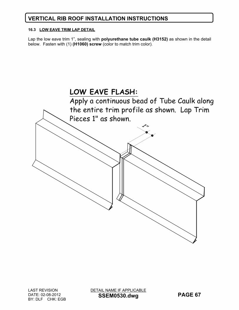
VERTICAL RIB ROOF INSTALLATION INSTRUCTIONS
LAST REVISIONDATE: 02-08-2012BY: DLF CHK: EGB
DETAIL NAME IF APPLICABLESSEM0530.dwg PAGE 67
16.3 LOW EAVE TRIM LAP DETAIL
Lap the low eave trim 1”, sealing with polyurethane tube caulk (H3152) as shown in the detail below. Fasten with (1) (H1060) screw (color to match trim color).

VERTICAL RIB ROOF INSTALLATION INSTRUCTIONS
LAST REVISIONDATE: 08-06-2019BY: EGB CHK: KMC
DETAIL NAME IF APPLICABLEV2SSEM0540.dwg PAGE 68
16.4 LOW EAVE STANDARD GUTTEREstablish a string line 6 3/8” beyond the low eave edge of the roof panel to aid in proper gutter bracket alignment.Apply 8” pre-cut mastic (H3640) to the end of the bracket directly under the pre-punched holes as shown.NOTE: Before the gutter bracket can be installed, the panel seam at the low eave must be hand crimped into a VR16 II-90 Seam.
Do Not crimp 16” up from the low end of the panel into a VR16 II-360 Seam. (The bracket will not fit up properly).
Place the gutter bracket (H4640) on the roof panel, holding the low eave end at the string line as established earlier. Gutter brackets are required at every other panel rib (2’-8” on center) U.N.O.Fasten the gutter bracket with (2) gutter bracket colored self-drilling screws (#14 x 1”).Apply ½” tape mastic (H3010) to the back lip of the gutter and fasten to the roof panel with (3) roof colored self- drilling screws (#14 x 1”).
NOTE: Clamping the gutter to the roof panel will allow for easier installation.
GUTTER PART NUMBERS GTA01 x 10’-1” GTA02 x 20’-2” GUTTER EXT. TRIM NUMBERS GTT01 x 10-1”
On some jobs, the end owner may specify that they want a larger capacity gutter system. Per the order contract it is possible to order this system. If required, the gutter extension trim would be installed on the gutter prior to installing the gutter. (See the detail below) The gutter would then be installed by using the same pervious steps.If the endwall is a standard rake trim condition, the gutter should extend 1” beyond the edge of the wall corner trim. Attach the gutter to the gutter bracket with (1) gutter colored self- drilling screw (#14x1). NOTE: THE GUTTER BRACKET SHOULD BE UNDER THE LIP OF THE GUTTER.If the endwall is a rake parapet trim condition, the gutter should be held back ½” from the face of the parapet wall.

VERTICAL RIB ROOF INSTALLATION INSTRUCTIONS
LAST REVISIONDATE: 09-08-2012BY: DLF CHK: EGB
DETAIL NAME IF APPLICABLEV2SSEM0550.dwg PAGE 69
16.5 GUTTER LAP DETAIL
Lap gutter 1”, sealing with (2) continuous beads of polyurethane tube caulk (H3152) to the end of the adjoining piece. Fasten with (10) pop rivets (H1100).
16.6 GUTTER END CAPS
Apply a continuous bead of polyurethane tube caulk (H3152) around three sides of the gutter end cap (H4000), close to the inside edge of the cap.
Insert the cap into the gutter leaving ½” of the cap exposed on all sides.
Fasten with pop rivets (H1100) at the front and back only. (6) total rivets required per cap.
Fasten the gutter/rake trim (GRA01) to the wall corner trim with (2) trim-colored self-drilling screws (#14 x 1”). Hold the trim piece tight to the back of and flush with the bottom of the gutter.
After the gutter end cap (H4000) has been installed, apply a continuous bead of polyurethane tube caulk (H3152) around the inside bends of the cap.
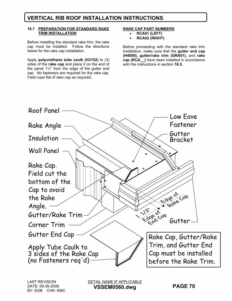
VERTICAL RIB ROOF INSTALLATION INSTRUCTIONS
LAST REVISIONDATE: 09-26-2008BY: EGB CHK: KMC
DETAIL NAME IF APPLICABLEVSSEM0560.dwg PAGE 70
16.7 PREPARATION FOR STANDARD RAKE TRIM INSTALLATION
Before installing the standard rake trim, the rake cap must be installed. Follow the directions below for the rake cap installation.
Apply polyurethane tube caulk (H3152) to (3) sides of the rake cap and place it on the end of the panel 1½” from the edge of the gutter end cap. No fasteners are required for the rake cap. Field cope flat of rake cap as required.
RAKE CAP PART NUMBERS RCA01 (LEFT) RCA02 (RIGHT)
Before proceeding with the standard rake trim installation, make sure that the gutter end cap (H4000), gutter/rake trim (GRA01), and rake cap (RCA__) have been installed in accordance with the instructions in section 16.5.
Rake Angle
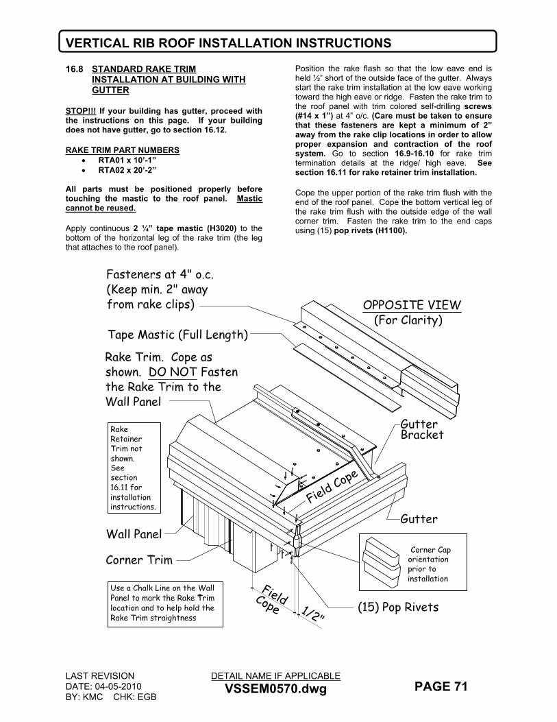
VERTICAL RIB ROOF INSTALLATION INSTRUCTIONS
LAST REVISIONDATE: 04-05-2010BY: KMC CHK: EGB
DETAIL NAME IF APPLICABLEVSSEM0570.dwg PAGE 71
16.8 STANDARD RAKE TRIM INSTALLATION AT BUILDING WITH GUTTER
STOP!!! If your building has gutter, proceed with the instructions on this page. If your building does not have gutter, go to section 16.12.
RAKE TRIM PART NUMBERS RTA01 x 10’-1” RTA02 x 20’-2”
All parts must be positioned properly before touching the mastic to the roof panel. Mastic cannot be reused.
Apply continuous 2 ¼” tape mastic (H3020) to the bottom of the horizontal leg of the rake trim (the leg that attaches to the roof panel).
Position the rake flash so that the low eave end is held ½” short of the outside face of the gutter. Always start the rake trim installation at the low eave working toward the high eave or ridge. Fasten the rake trim to the roof panel with trim colored self-drilling screws (#14 x 1”) at 4” o/c. (Care must be taken to ensure that these fasteners are kept a minimum of 2” away from the rake clip locations in order to allow proper expansion and contraction of the roof system. Go to section 16.9-16.10 for rake trim termination details at the ridge/ high eave. See section 16.11 for rake retainer trim installation.
Cope the upper portion of the rake trim flush with the end of the roof panel. Cope the bottom vertical leg of the rake trim flush with the outside edge of the wall corner trim. Fasten the rake trim to the end caps using (15) pop rivets (H1100).
FieldCope 1/2"
Field Cope

VERTICAL RIB ROOF INSTALLATION INSTRUCTIONS
LAST REVISIONDATE: 04-05-2018BY: SDF CHK: EGB
DETAIL NAME IF APPLICABLESSEM0580.dwg PAGE 72
16.9 RAKE TRIM LAP DETAIL
Lap the rake trim 1”, sealing with a continuous bead of polyurethane caulk (H3152) to the end of the adjoining piece. Fasten with (5) trim colored self- drilling screws (#14 x 1”) and (5) pop rivets (H1100).
Do not attach the rake trim to the wall panel (or whatever wall material is being utilized). Go to the rake retainer trim installation instructions in section 16.11.

VERTICAL RIB ROOF INSTALLATION INSTRUCTIONS
LAST REVISIONDATE: 04-05-2010BY: KMC CHK: EGB
DETAIL NAME IF APPLICABLEV2SSEM0590.dwg PAGE 73
16.10 STANDARD RAKE TRIM TERMINATION AT RIDGE
If your building has a ridge, extend the standard rake trim 2” past the end of the roof panel. If your building is a single slope, go to section 16.10.Field cut a Ridge Closure Zee (TRCZ) long enough to lap 2” onto the first full Ridge Closure Zee and to create a 1” tab.
Apply a piece of 2 ¼” tape mastic (H3020) to the bottom edge of the Ridge Closure Zee stopping 2” short of the lapped end.
Next apply Butyl Caulk (H3151) as shown below in the lapped area.
Before installing the Ridge Closure Zee (TRCZ), field cut a small slit into the Rake Trim as shown. Place a small piece of 2 ¼” tape mastic (H3020) on the vertical surface of the rake as shown below (for the TRCZ tab).
If required, prepare the cover flash by running two beads of Butyl Tube Caulk (H3151) in the corners of the trim as shown.
Place the Ridge Closure Zee into the rake trim slit and underneath the roof panel. Fasten through the roof panel and into the next full Closure Zee with #14 x 1” fasteners. Fasten the tab and lap with (1) #14 x 1” fastener.
Field Cut an Ridge Closure Zee to the Proper Length (add 1" to length to allow for a tab as shown)
NOTE:See Section 13.8 for More Ridge Closure Zee Information.

VERTICAL RIB ROOF INSTALLATION INSTRUCTIONS
LAST REVISIONDATE: 09-26-2008BY: EGB CHK: KMC
DETAIL NAME IF APPLICABLEV2SSEM0600.dwg PAGE 74
16.11 RAKE TRIM TERMINATION AT HIGH SIDE
If your building is a single slope, extend the rake trim 1” past the outside face of the wall corner trim. Field cope the vertical leg of the rake trim flush to the outside face of the wall corner trim.Field cope the upper section of the rake trim back 1” as shown. Additionally, cope the “sloped” face of the rake trim back 2 7/8” at an angle to match 2 7/8” coped top and back leg.Field cut a Ridge Closure Zee (TRCZ) long enough to lap 2” onto the first full Ridge Closure Zee and to create a 1” tab. Apply a piece of tape mastic (H3020) to the bottom edge of the Ridge Closure Zee stopping 2” short of the lapped end.
Next apply Butyl Caulk (H3151) as shown below in the lapped area.Before installing the Ridge Closure Zee (TRCZ), field cut a small slit into the Rake Trim as shown. Place a small piece of tape mastic (H3020) on the vertical surface of the rake as shown below (for the TRCZ tab).If required, prepare the cover flash by running two beads of Butyl Tube Caulk (H3151) in the corners of the trim as shown.Place the Ridge Closure Zee into the rake trim slit (See Sec 16.09 for slitting trim detail) and underneath the roof panel. Fasten through the roof panel and into the next full Closure Zee with #14 x 1” fasteners. Fasten the tab and lap with (1) #14 x 1” fastener.
SECTION "A"NOTE:See Section 13.8 for More Ridge Closure Zee Information.

VERTICAL RIB ROOF INSTALLATION INSTRUCTIONS
LAST REVISIONDATE: 08-2-2012BY: AES CHK: EGB
DETAIL NAME IF APPLICABLEVSSEM0610.dwg PAGE 75
16.12 RAKE RETAINER TRIM INSTALLATION
The rake retainer trim allows the standard rake trim to float with the expansion and contraction of the roof system. Proper positioning of the rake retainer trim will allow the standard rake trim to function as designed.
Position the rake retainer trim over the drip edge on the standard rake flash, aligning the low eave
end flush with the outside face of the wall corner trim. Fasten the rake retainer trim to the wall panel with trim colored self-drilling screws (H1060) at ends and at 12” o/c
Do not lap the rake retainer trim. The ends should be butted together.
Gutter
GutterRake Trim
Wall Panel
Roof Panel
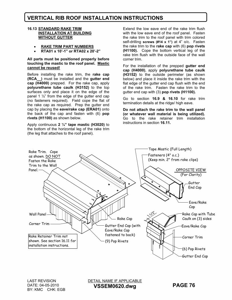
VERTICAL RIB ROOF INSTALLATION INSTRUCTIONS
LAST REVISIONDATE: 04-05-2010BY: KMC CHK: EGB
DETAIL NAME IF APPLICABLEVSSEM0620.dwg PAGE 76
16.13 STANDARD RAKE TRIM INSTALLATION AT BUILDING WITHOUT GUTTER
RAKE TRIM PART NUMBERS RTA01 x 10’-1” or RTA02 x 20’-2”
All parts must be positioned properly before touching the mastic to the roof panel. Mastic cannot be reused!Before installing the rake trim, the rake cap (RCA__) must be installed and the gutter end cap (H4000) prepped. For the rake cap, apply polyurethane tube caulk (H3152) to the top surfaces only and place it on the edge of the panel 1 ½” from the edge of the gutter end cap (no fasteners required). Field cope the flat of the rake cap as required. Prep the gutter end cap by placing the eave/rake cap (ERA01) onto the back of the cap and fasten with (6) pop rivets (H1100) as shown below.
Apply continuous 2 ¼” tape mastic (H3020) to the bottom of the horizontal leg of the rake trim (the leg that attaches to the roof panel).
Extend the low eave end of the rake trim flush with the low eave end of the roof panel. Fasten the rake trim to the roof panel with trim colored self-drilling screws (#14 x 1”) at 4” o/c. Fasten the rake trim to the rake cap with (6) pop rivets (H1100). Cope the bottom vertical leg of the rake trim flush with the outside face of the wall corner trim.
For the installation of the prepped gutter end cap (H4000), apply polyurethane tube caulk (H3152) to the outside perimeter (as shown below) and place it inside the rake trim with the flat edge of the gutter end cap flush with the end of the rake trim. Fasten the rake trim to the gutter end cap with (3) pop rivets (H1100).Go to section 16.9 & 16.10 for rake trim termination details at the ridge/ high eave.
Do not attach the rake trim to the wall panel (or whatever wall material is being utilized). Go to the rake retainer trim installation instructions in section 16.11.

VERTICAL RIB ROOF INSTALLATION INSTRUCTIONS
LAST REVISIONDATE: 02-08-2012BY: DLF CHK: EGB
DETAIL NAME IF APPLICABLEVSSEM0630.dwg PAGE 77
16.14 RAKE PARAPET TRIM INSTALLATION
If your building has gutter, hold the gutter back ½” short of the inside face of the parapet wall.
Apply polyurethane tube caulk (H3152) around three sides of the gutter end cap (H4000) and install in the gutter. Leave ½” of the end cap exposed at the end of the gutter. Fasten with (10) pop rivets (H1100).
Apply continuous 2 ¼” tape mastic (H3020) to the bottom of the horizontal leg of the rake parapet trim (RPA01) (the leg that attaches to the roof panel).
All parts must be positioned properly before touching the mastic to the roof panel. Mastic cannot be reused!
Fasten the rake parapet trim to the roof panel with trim colored self- drilling screws (#14 x 1”) at 4” o/c
Apply polyurethane tube caulk (H3152) around the perimeter of the rake parapet cap and slide into place. Fasten with (9) self-drilling screws (#14 x 1”).
RAKE PARAPET CAP PART NO.’S RCB01 – (LEFT) RCB02 – (RIGHT)
Lap the rake parapet trim 1”, sealing with (2) continuous beads of polyurethane caulk (H3152) to the end of the adjoining piece. Fasten with (6) trim colored screws.
If your building does not have gutter, these same instructions above apply. However, you will not need the gutter end cap (H4000).
For rake parapet trim termination details at the ridge or high eave refer to section 16.14.

VERTICAL RIB ROOF INSTALLATION INSTRUCTIONS
LAST REVISIONDATE: 04-05-2010BY: KMC CHK: EGB
DETAIL NAME IF APPLICABLEV2SSEM0640.dwg PAGE 78
16.15 STANDARD RAKE PARAPET TRIM TERMINATION AT HIGH EAVE OR RIDGE
Extend the rake parapet trim 2” past the end of the roof panel.
Field cut a Ridge Closure Zee (TRCZ) long enough to lap 2” onto the first full Ridge Closure Zee and to create a 1” tab.
Apply a piece of tape mastic (H3020) to the bottom edge of the Ridge Closure Zee stopping 2” short of the lapped end.
Next apply Butyl Caulk (H3151) as shown below in the lapped area.
Before installing the Ridge Closure Zee (TRCZ), field cut a small slit into the Rake Trim as shown. Place a small piece of tape mastic (H3020) on the vertical surface of the rake as shown below (for the TRCZ tab).
If required, prepare the cover flash by running two beads of Butyl Tube Caulk (H3151) in the corners of the trim as shown.
Place the Ridge Closure Zee into the rake trim slit and underneath the roof panel. Fasten through the roof panel and into the next full Closure Zee with #14 x 1” fasteners. Fasten the tab and lap with (1) #14 x 1” fastener.
Field Cut an Ridge Closure Zee to the Proper Length (add 1" to length to allow for a tab as shown)
NOTE:See Section 13.8 for More Ridge Closure Zee Information.
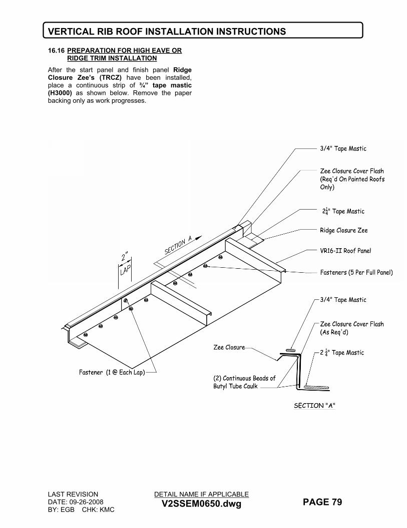
VERTICAL RIB ROOF INSTALLATION INSTRUCTIONS
LAST REVISIONDATE: 09-26-2008BY: EGB CHK: KMC
DETAIL NAME IF APPLICABLEV2SSEM0650.dwg PAGE 79
16.16 PREPARATION FOR HIGH EAVE OR RIDGE TRIM INSTALLATION
After the start panel and finish panel Ridge Closure Zee’s (TRCZ) have been installed, place a continuous strip of ¾” tape mastic (H3000) as shown below. Remove the paper backing only as work progresses.
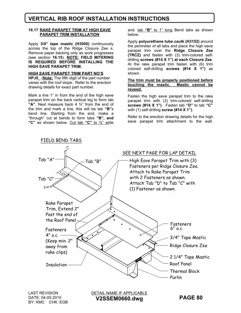
VERTICAL RIB ROOF INSTALLATION INSTRUCTIONS
LAST REVISIONDATE: 04-05-2010BY: KMC CHK: EGB
DETAIL NAME IF APPLICABLEV2SSEM0660.dwg PAGE 80
16.17 RAKE PARAPET TRIM AT HIGH EAVE PARAPET TRIM INSTALLATION
Apply 3/4” tape mastic (H3000) continuously across the top of the Ridge Closure Zee s. Remove paper backing only as work progresses (see section 16.15). NOTE: FIELD MITERING IS REQUIRED BEFORE INSTALLING THE HIGH EAVE PARAPET TRIM.HIGH EAVE PARAPET TRIM PART NO’SHPJ0_ (Note: The fifth digit of the part number varies with the roof slope. Refer to the erection drawing details for exact part number.
Mark a line 1” in from the end of the high eave parapet trim on the back vertical leg to form tab “A”. Next measure back 4 ¾” from the end of the trim and mark a line, this will be tab “B”s bend line. Starting from the end, make a “through” cut at bends to form tabs “B”, and “C” as shown below. Cut tab “C” to ¾” wide
and. tab “B” to 1” long Bend tabs as shown below.
Apply polyurethane tube caulk (H3152) around the perimeter of all tabs and place the high eave parapet trim over the Ridge Closure Zee (TRCZ) and fasten with (3) trim-colored self-drilling screws (#14 X 1”) at each Closure Zee. At the rake parapet trim fasten with (6) trim colored self-drilling screws (#14 X 1”) as shown.
The trim must be properly positioned before touching the mastic. Mastic cannot be reused.Fasten the high eave parapet trim to the rake parapet trim with (3) trim-colored self-drilling screws (#14 X 1”). Fasten tab “D” to tab “C” with (1) self-drilling screw (#14 X 1”).Refer to the erection drawing details for the high eave parapet trim attachment to the wall.
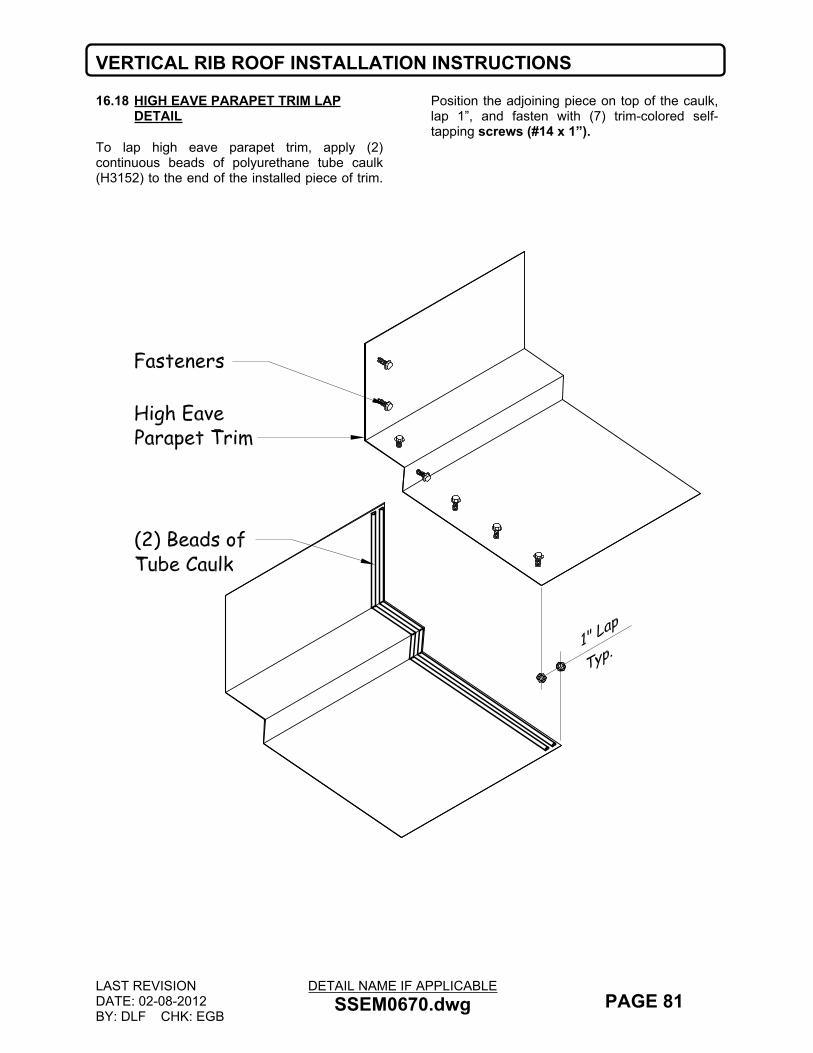
VERTICAL RIB ROOF INSTALLATION INSTRUCTIONS
LAST REVISIONDATE: 02-08-2012BY: DLF CHK: EGB
DETAIL NAME IF APPLICABLESSEM0670.dwg PAGE 81
16.18 HIGH EAVE PARAPET TRIM LAP DETAIL
To lap high eave parapet trim, apply (2) continuous beads of polyurethane tube caulk (H3152) to the end of the installed piece of trim.
Position the adjoining piece on top of the caulk, lap 1”, and fasten with (7) trim-colored self-tapping screws (#14 x 1”).

VERTICAL RIB ROOF INSTALLATION INSTRUCTIONS
LAST REVISIONDATE: 09-26-2008BY: EGB CHK: KMC
DETAIL NAME IF APPLICABLEV2SSEM0680.dwg PAGE 82
16.19 PREPARATION FOR SCULPTURED HIGH EAVE TRIM INSTALLATION
Before installing the high eave trim, apply polyurethane tube caulk (H3152) around the perimeter of the corner cap (H4000). Slide the cap into the end of the standard rake trim, leaving ½” exposed as shown below.
Apply 3/4” tape mastic (H3000) continuously across the Ridge Closure Zee. Remove paper backing only as work progresses.
Also see section 16.15 for additional mastic details at the Ridge Closure Zee s.

VERTICAL RIB ROOF INSTALLATION INSTRUCTIONS
LAST REVISIONDATE: 09-26-2008BY: EGB CHK: KMC
DETAIL NAME IF APPLICABLEV2SSEM0690.dwg PAGE 83
16.20 SCULPTURED HIGH EAVE TRIM INSTALLATION
Lay the high eave trim over the Ridge Closure Zee and fasten with (3) trim-colored self-drilling screws (#14 x 1”). NOTE: The high eave sculptured trim must be properly positioned before touching the mastic. Remove the paper backing only as work progresses.
SCULPTURED HIGH EAVE TRIM PART NO’S HEC01 x 10’-1” HEC02 x 20’-2”
Field cope the high eave trim similar to the rake trim except do not cut the sloped face. Instead, fold the sloped face over the sloped face of the rake trim. Caulk all around with polyurethane tube caulk (H3152) and fasten with (3) pop rivets (H1100).
Fasten the high eave trim and the rake trim to the corner cap with (7) pop rivets (H1100). Fasten the top leg of the high eave trim with (6) trim-colored self- drilling screws (#14x 1”).
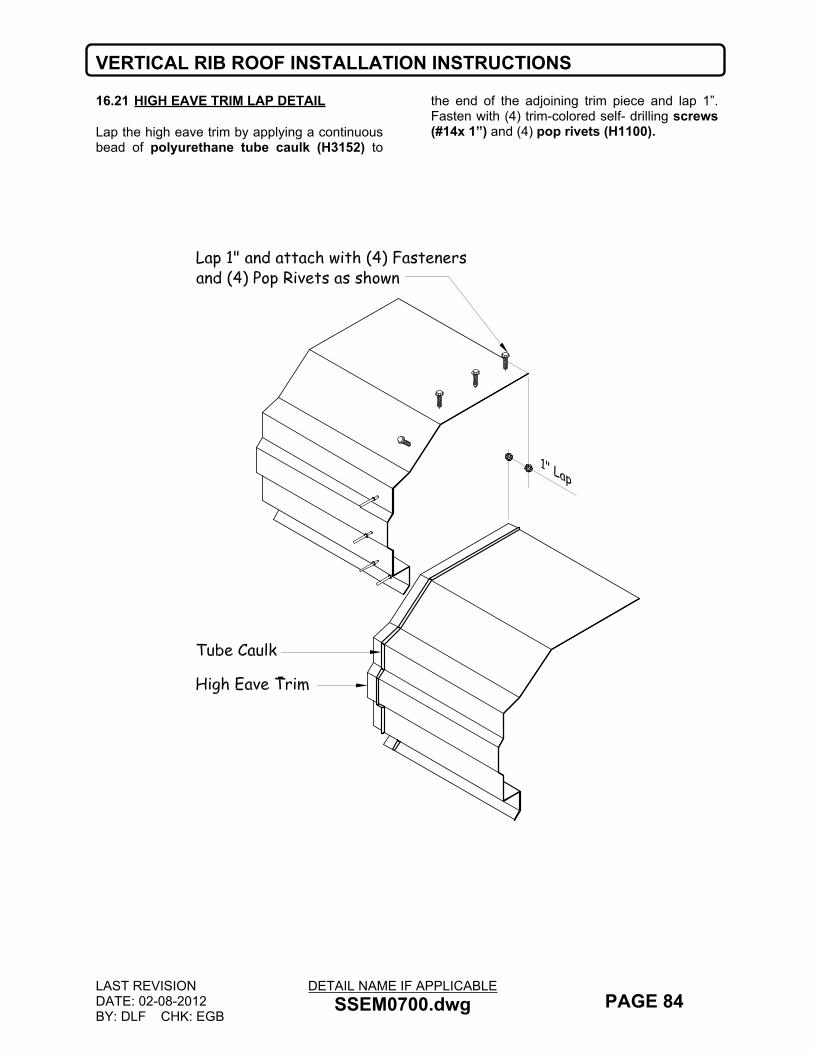
VERTICAL RIB ROOF INSTALLATION INSTRUCTIONS
LAST REVISIONDATE: 02-08-2012BY: DLF CHK: EGB
DETAIL NAME IF APPLICABLESSEM0700.dwg PAGE 84
16.21 HIGH EAVE TRIM LAP DETAIL
Lap the high eave trim by applying a continuous bead of polyurethane tube caulk (H3152) to
the end of the adjoining trim piece and lap 1”. Fasten with (4) trim-colored self- drilling screws (#14x 1”) and (4) pop rivets (H1100).

VERTICAL RIB ROOF INSTALLATION INSTRUCTIONS
LAST REVISIONDATE: 09-26-2008BY: EGB CHK: KMC
DETAIL NAME IF APPLICABLEV2SSEM0705.dwg PAGE 85
16.22 METAL PEAK BOX, PEAK PLATE AND RIDGE CAP PREPERATION
Prior to installing the first or last piece of ridge cap, the Peak Box and Peak Plate need to be installed. PEAK BOX:Start by field cutting the back leg of the peak box off as shown below. Next apply a continuous bead of polyurethane tube caulk (H3152) on the underside of the Peak Box where it comes in contact with the rake trims. Apply polyurethane tube caulk (H3152) to any gaps on the underside of the peak box in the mitered area.RIDGE CAP Next, for proper ridge cap fit up with the peak cap, the ridge cap will need to be field notched. Start by marking a line on the ridge cap back 3” from the leading edge of the ridge cap. Cut along the first bend up from the bottom flange to the 3” line. For tab “A” (on the vertical face) cut up 1” along the 3” marked line as shown. Bend tab up to match roof slope.For tab “B” (on the flange of the ridge cap) Mark a line 2 ¼” back from the leading edge of
the ridge cap. Cut along this line. Bend tab up 90°.
PEAK PLATE:Start by applying a continuous strip of ¾” tape mastic (H3000) to the top of the four tabs and the underside of the sloped tab as shown. Next place the Peak Plate inside of the ridge cap and fasten with (6) Trim colored #14 x 1” fasteners.
PEAK BOX AND PEAK PLATE PART NUMBERS
Roof Slope
Peak Box Peak Plate
.5:12 MPB50 MPP501:12 MPB01 MPP012:12 MPB02 MPP023:12 MPB03 MPP034:12 MPB04 MPP045:12 MPB05 MPP056:12 MPB06 MPP06

VERTICAL RIB ROOF INSTALLATION INSTRUCTIONS
LAST REVISIONDATE: 09-26-2008BY: EGB CHK: KMC
DETAIL NAME IF APPLICABLEV2SSEM0730.dwg PAGE 86
16.23 METAL PEAK BOX & PEAK PLATE INSTALLATION AT STANDARD RAKE TRIM
Center the prepared Peak Box over the ridge. Once centered, push the peak box down and over the rake trims. Make sure the back lip of the peak box is between the ridge closure zee and the rake trim. To achieve this, you may need to back out the fastener on the ridge closure zee tab and then re-install. Finish installing the rake retainer trim over the peak box.Install continuous 3/4” tape mastic (H3000) along the top of the ridge closure zees on both sides of the ridge. Remove the paper backing only as work progresses.
After the Peak Box is in place, place 3/4” tape mastic (H3000) on tabs “A” & “B” as shown. Next, install short pieces of 3/4” tape mastic (H3000) to the flat portion of the ridge cap (as shown).
Center the prepared section of Ridge Cap over the ridge closure zees and fasten with (5) ridge cap colored self-drilling screws (#14 x 1”) per panel width. (2” from each rib and 5” o/c in between). Be sure that the edge of the ridge cap is flush with the sloped face.Fasten the Ridge Cap to the rake trim using self-drilling screws (#14 x 1”).

VERTICAL RIB ROOF INSTALLATION INSTRUCTIONS
LAST REVISIONDATE: 09-26-2008BY: EGB CHK: KMC
DETAIL NAME IF APPLICABLEV2SSEM0710.dwg PAGE 87
16.24 STD RIDGE CAP INSTALLATION WITH METAL PEAK BOX
Install continuous 3/4” tape mastic (H3000) along the top of the Ridge Closure Zees (TRCZ) on both sides of the ridge. Remove the paper backing only as work progresses.
Start the ridge cap flush with the sloped edge of the rake trim as shown in the detail below.
Ridge cap must be properly positioned before touching the mastic. Mastic cannot be reused.
Center the ridge cap over the Ridge Closure Zees and fasten with (5) ridge cap colored self-drilling screws (#14 x 1”) per panel width. (2” from each rib and 5” o/c in between).
Refer to the next page for ridge cap lap details.

VERTICAL RIB ROOF INSTALLATION INSTRUCTIONS
LAST REVISIONDATE: 07-28-2016BY: SAA CHK: KMC
DETAIL NAME IF APPLICABLEV2SSEM0720.dwg PAGE 88
16.25 RIDGE CAP LAP DETAILS
IMPORTANT NOTE: DO NOT LAP THE RIDGE CAP AT A PANEL RIB.
Ridge cap is to be lapped 4”, utilizing (2) beads of BUTYL tube caulk (H3151). Also apply the tube caulk to the tape mastic as shown.
DO NOT USE FASTENERS AT RIDGE CAP LAPS. DOING SO WILL NOT ALLOW THE RIDGE CAP TO EXPAND AND CONTRACT AS DESIGNED.
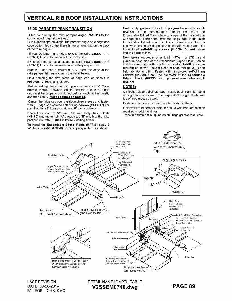
VERTICAL RIB ROOF INSTALLATION INSTRUCTIONS
LAST REVISIONDATE: 09-26-2014BY: EGB CHK: KMC
DETAIL NAME IF APPLICABLEV2SSEM0740.dwg PAGE 89
16.26 PARAPET PEAK TRANSITION Start by running the rake parapet angle (MAP01) to the centerline of ridge. (Low Slope) On higher slope buildings, run parapet angle past ridge and cope bottom leg so that there is not a large gap on the back of the rake angle. If your building has a ridge, extend the rake parapet trim (RPA01) flush with the end of the roof panel.If your building is a single slope, stop the rake parapet trim (RPA01) flush with the inside face of the parapet wall.Start the ridge cap a maximum of ½” from the edge of the rake parapet trim as shown in the detail below.Field notching the first piece of ridge cap as shown in FIGURE. A. Bend all tabs 90. Before setting the ridge cap, place a piece of ¾” Tape mastic (H3000) between tab “B” and the rake trim. Ridge cap must be properly positioned before touching the mastic and tube caulk. Mastic cannot be reused. Center the ridge cap over the ridge closure zees and fasten with (3) ridge cap colored self-drilling screws (#14 x 1”) per panel width. (2” from each rib and 6” o/c in between). Caulk between tab “A” and “B” with Poly Tube Caulk (H3152) and fasten tab “A” through tab “B” and into the rake parapet trim with (1) (#14 x 1”) self- drilling screw.To install the Expandable Edged Flash, (RPT30) apply 2 ¼” tape mastic (H3020) to rake parapet trim as shown.
Next apply generous bead of polyurethane tube caulk (H3152) to the corners rake parapet trim. Form the Expandable Edged Flash piece to shape of the parapet trim & ridge cap, center the over the ridge cap. Next, push Expandable Edged Flash tight into corners and form a bellows in the center of the flash as shown. Fasten with (14) trim-colored self-drilling screws (H1050). Do not fasten into the parapet trim.Next, take short pieces of jamb trim (JTA__ or JTD__) and place on each side of the Expandable Edged Flash. Fasten into the rake angle with one trim-colored self-drilling screw (H1050) as shown. Take a piece of head trim (HTA__) and field tab into jamb trim. Fasten with trim-colored self-drilling screws (H1050). Caulk the perimeter of the Expandable Edged Flash (RPT30) with polyurethane tube caulk (H3152).NOTES: On higher slope buildings, taper mastic back from high point of ridge cap as shown. Taper expandable edged flash over top of tape mastic as well.Fasteners into masonry and counter flash by others.Field work rake parapet trims to ensure weather tightness as required on ALL buildings. Transition trims not supplied on buildings greater then 6:12.
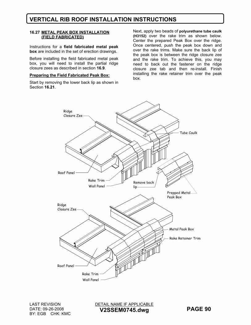
VERTICAL RIB ROOF INSTALLATION INSTRUCTIONS
LAST REVISIONDATE: 09-26-2008BY: EGB CHK: KMC
DETAIL NAME IF APPLICABLEV2SSEM0745.dwg PAGE 90
16.27 METAL PEAK BOX INSTALLATION (FIELD FABRICATED)
Instructions for a field fabricated metal peak box are included in the set of erection drawings.
Before installing the field fabricated metal peak box, you will need to install the partial ridge closure zees as described in section 16.9.
Preparing the Field Fabricated Peak Box:Start by removing the lower back lip as shown in Section 16.21.
Next, apply two beads of polyurethane tube caulk (H3152) over the rake trim as shown below. Center the prepared Peak Box over the ridge. Once centered, push the peak box down and over the rake trims. Make sure the back lip of the peak box is between the ridge closure zee and the rake trim. To achieve this, you may need to back out the fastener on the ridge closure zee tab and then re-install. Finish installing the rake retainer trim over the peak box.

VERTICAL RIB ROOF INSTALLATION INSTRUCTIONS
LAST REVISIONDATE: 01/06/2012BY: DLF CHK: EGB
DETAIL NAME IF APPLICABLEV2SSEM0750.dwg PAGE 91
16.28 LOW PROFILE RIDGE CAP INSTALLATION
Install continuous 3/4” tape mastic (H3000) along the top of the ridge closure zees on both sides of the ridge and under the coped out part of the ridge cap. Remove the paper backing only as work progresses.Start the ridge cap a maximum of ½” from the edge of the rake trim as shown in the detail below. Next, for proper ridge cap fit up with the metal peak box, the ridge cap will need to be field notched. Start by marking a line on the ridge cap back 2 ½” from the leading edge on the horizontal and vertical surfaces of the ridge cap. Next, for tab “A” cut 1 ¾” back along the top shoulder of the ridge cap. Make the second cut 1 ¾” in the lower shoulder of the cap. (same as the first cut. Next bend the tab out using the 2 ½” start line. Trim the tab to ¾” long.For tab “B” bend up at the 2 ½” line and trim to ¾” wide. Repeat steps for the other side of the cap.
Before setting the ridge cap, place a bead of polyurethane tube caulk (H3152) caulk between tab “B” and the rake trim.Ridge cap must be properly positioned before touching the mastic and tube caulk. Mastic cannot be reused.Center the ridge cap over the ridge closure zees and fasten with (3) ridge cap colored self-drilling screws (#14 x 1”) per panel width. (2” from each rib and 6” o/c in between). Fasten tab ”B” on the end with (1) trim colored self- drilling screw (#14 x 1”) then, caulk between tab “A” and “B” with polyurethane tube caulk (H3152) and fasten through tab “B” and into the rake trim with (1) self- drilling screw (#14 x 1”) Refer to page 88 for ridge cap lap details.RIDGE CAP PART NUMBERSREFER TO THE ERECTION DRAWING RIDGE DETAIL FOR THIS PART NUMBER

NUCOR BUILDING SYSTEMS VR16 II ERECTION MANUAL
17.0 VR16 II CHECKLIST
92
17.0VR16 II CHECKLIST
The following checklist is intended to assist the builder and/or erector in troubleshooting and punching out the NUCOR VR16 II ROOF SYSTEM. This list is not intended to serve as a certification of the roof system, because many details such as mastic installation are impossible to inspect after the roof has been erected. However, in conjunction with continuous quality control measures during the erection process, this list should help insure a safe, weather-tight roof system.Nucor recommends that detailed notes be taken during the inspection and punching out of the roof. The erector or the actual person doing the work should have access to these notes. Do not place pencil markings on the galvalume panels, because pencil lead will cause rusting and will void your galvalume warranty. Instead, consider using clothes pins attached to the seam of the panel to point out problem/unfinished areas. These work well, do not create a mess, and can be seen from across the roof.
VR16 II ROOF DETAIL COMPLIANCE LIST
LOW EAVE CONDITION
Y N Is the first bend in the eave plate aligned with the edge of the roof member?Y N Does the eave plate extend all the way to the endwall steel line?Y N Is the eave plate fastened at 6” on center?Y N Is mastic applied continuous along the top of the eave plate?Y N Has tape pad/butyl tube caulk been installed on the low eave panel rib prior to next panel installation?Y N Is the insulation visible at the eave plate (from the outside)? (If so, this is not correct.)Y N Are the gutter brackets installed per contract? (at 1’-4” or 2’-8” O.C.)Y N Are there (5) fasteners installed into the flat of the panel at the low eave?
RAKE CONDITION
Y N If the building has insulation, are the rake angle clips installed over the top of the insulation?Y N Are the rake trim fasteners installed through rake clips? (If so, this is not correct.)Y N Are the rake trim fasteners located 2” to either side of the rake clips? (To allow roof to float properly.)Y N Are the rake trim fasteners installed at 4” on center?
ENDLAP CONDITION
Y N Do you have the swaged panel in the proper location? The swaging is on the lower end of the up slope panel.Y N Is the endlap mastic and tube caulk in the proper location?Y N Are the panel ends lapped 6” at an endlap?Y N Does the endlap have a back-up plate with all (3) tabs engaged?Y N Has the endlap tube caulk been properly placed in the panel notch?Y N Are the back-up plates properly engaged by the fasteners?Y N Are there any stripped or missing fasteners at the panel endlaps?Y N Are all oversized fasteners properly tightened?Y N Are there (5) fasteners installed at the endlap?
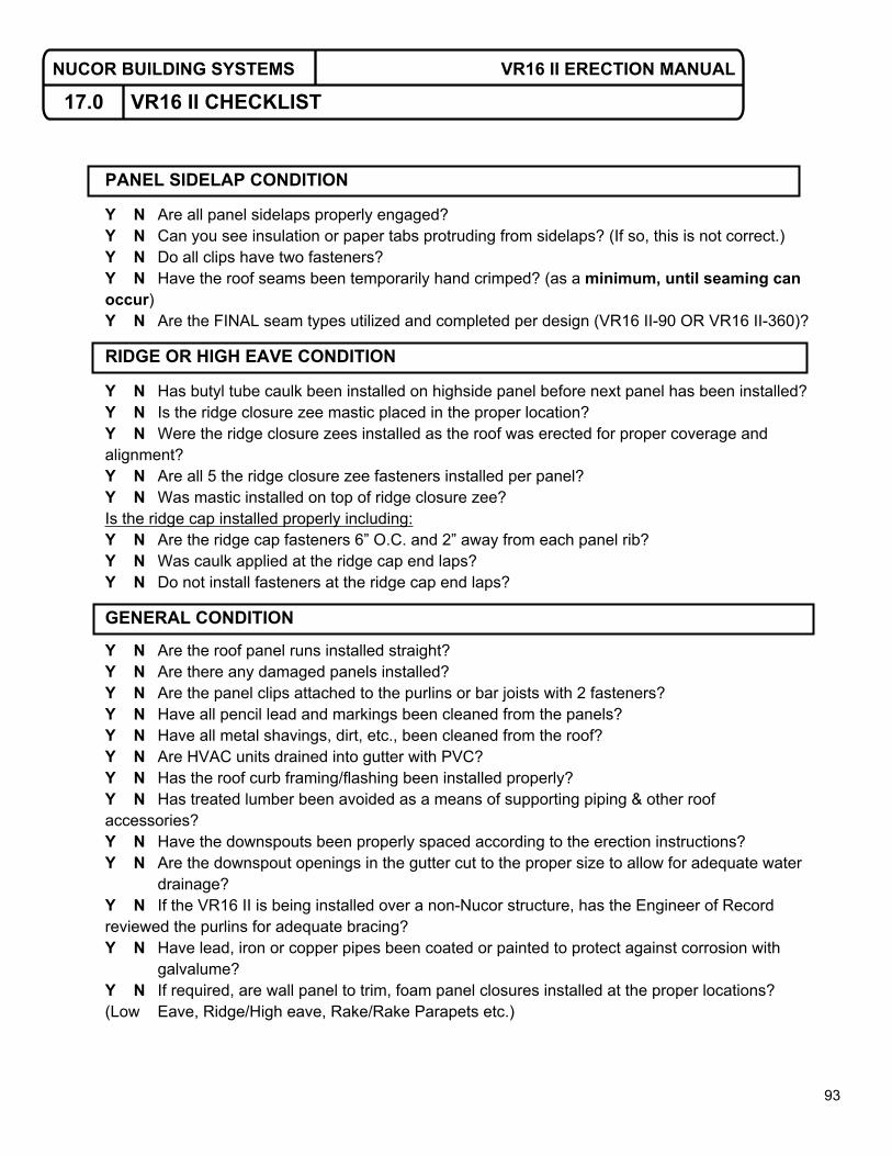
NUCOR BUILDING SYSTEMS VR16 II ERECTION MANUAL
17.0 VR16 II CHECKLIST
93
PANEL SIDELAP CONDITION
Y N Are all panel sidelaps properly engaged?Y N Can you see insulation or paper tabs protruding from sidelaps? (If so, this is not correct.)Y N Do all clips have two fasteners?Y N Have the roof seams been temporarily hand crimped? (as a minimum, until seaming can occur)Y N Are the FINAL seam types utilized and completed per design (VR16 II-90 OR VR16 II-360)?
RIDGE OR HIGH EAVE CONDITION
Y N Has butyl tube caulk been installed on highside panel before next panel has been installed?Y N Is the ridge closure zee mastic placed in the proper location?Y N Were the ridge closure zees installed as the roof was erected for proper coverage and alignment?Y N Are all 5 the ridge closure zee fasteners installed per panel?Y N Was mastic installed on top of ridge closure zee?Is the ridge cap installed properly including:Y N Are the ridge cap fasteners 6” O.C. and 2” away from each panel rib?Y N Was caulk applied at the ridge cap end laps?Y N Do not install fasteners at the ridge cap end laps?
GENERAL CONDITION
Y N Are the roof panel runs installed straight?Y N Are there any damaged panels installed?Y N Are the panel clips attached to the purlins or bar joists with 2 fasteners?Y N Have all pencil lead and markings been cleaned from the panels?Y N Have all metal shavings, dirt, etc., been cleaned from the roof?Y N Are HVAC units drained into gutter with PVC?Y N Has the roof curb framing/flashing been installed properly?Y N Has treated lumber been avoided as a means of supporting piping & other roof accessories?Y N Have the downspouts been properly spaced according to the erection instructions?Y N Are the downspout openings in the gutter cut to the proper size to allow for adequate water
drainage?Y N If the VR16 II is being installed over a non-Nucor structure, has the Engineer of Record reviewed the purlins for adequate bracing?Y N Have lead, iron or copper pipes been coated or painted to protect against corrosion with
galvalume?Y N If required, are wall panel to trim, foam panel closures installed at the proper locations? (Low Eave, Ridge/High eave, Rake/Rake Parapets etc.)