Embed Size (px)
Citation preview

1
YASKAWA AC DriveYASKAWA AC DriveL1000AL1000A
for Elevator Applicationsfor Elevator Applications
200 V Class 1.5 to 110 kW400 V Class 1.5 to 110 kW
JQA-0422 JQA-EM0498
Certified forISO9001 andISO14001
The Lift DriveThe Lift Drive

2
Control Mode Starting Torque Speed Range Motor Encoders and Option Cards
V/f Control 150% at 3 Hz* 1:40 N/AOpen Loop Vector Control 200% at 0.3 Hz* 1:200 N/A
Closed Loop Vector Control
200% at0 r/min*1 1:1500
Incremental Encoders:- PG-X3 (Line Driver)- PG-B3 (Complementary)
Closed Loop Vector Control for PM
200% at0 r/min* 1:1500
Incremental Encoders:- PG-X3 (Line Driver) - PG-B3 (Complementary) Absolute Encoders: - PG-F3 (ECN1313,HIPERFACE) - PG-E3 (HEIDENHAIN ERN1387)
11..Matching Every NeedMatching Every Need
Cutting-edge drive technology allows L1000 to run a newly installed gearless synchronous motor, or a refurbished geared induction motor. This minimizes equipment required for your application.
L1000
Capacity Range
200 V Class 1.5 to 110kW400 V Class 1.5 to 110kW *Some models not yet available.
Control Mode
PM motors ・Closed Loop Vector Control for PM motors (SPM/IPM drive)
Induction motors ・V/f Control・Open Loop Vector Control・Closed Loop Vector Control
High-performance current vector control generates powerful starting torque and allows precision control at low speeds.
Interfaces to match gearless, SPM synchronous motors and every type of absolute encoder. High resolution and pole position detection for a smooth and safe ride.
*Drive and motor must be matched appropriately.
Easily fit into compact machine rooms by combining the world's smallest drive in its class with the light, efficient design of a PM motor.
L1000’s slender design can be installed into a slender control panel. Depth of 200 mm for models up to 18.5 kW, 300 mm for 22 kW to 75kW
Take advantage of Side-by-Side installation* when storage space is limited. *For models up to 18.5 kW.
Slender design
Previous modelPrevious model
L1000
42% 42% smallersmaller
Drive Dimension Comparison Example shows a 400 V Class, 15 kW drive
Improved operation efficiencyL1000 calculates the stopping distance to minimize operation
time. “Direct Landing” function is also available.These features improve operation efficiency as well as greater stopping precision.
Short Floor minimizes the “creep speed” time for faster, more efficient operation.
Faster Operation Time Short FloorDirect Landing
Loaded with AutoLoaded with Auto--Tuning FeaturesTuning FeaturesL1000 is loaded with a variety of Auto-Tuning methods to ensure top performance.Rotational Auto-Tuning and Stationary Auto-Tuning are available for induction motors as well as synchronous motors.
Motor tuning features optimize drive settings without needing to disconnect the rope or car.Tuning features for connected machinery.
Motor Tuning
Rotational Auto-Tuning
Applications requiring high starting torque, high speed, and high accuracy. Tuning is performed on the motor alone, uncoupled from the load.
Stationary Auto-Tuning
Applications where the motor must remain connected to the load during the auto-tuning process.
Motor ResistanceAuto-Tuning
For re-tuning when the cable length between the motor/drive has changed or when motor/drive capacities are different.
Encoder Offset Auto-Tuning
Fine tunes the home pulse position when using an encoder with a synchronous motor. Possible with both Rotational and Stationary Auto-Tuning.
Brand new Auto-Tuning methods allow L1000 to continuously analyze changes in motor characteristics during run for highly precise speed control (when using Open Loop Vector Control)
Types of Auto-Tuning
Runs Induction and Synchronous MotorsRuns Induction and Synchronous Motors Designed Compact for Tight Machine RoomsDesigned Compact for Tight Machine Rooms
Compatible with a Wide Range of EncodersCompatible with a Wide Range of Encoders
Load Tuning
Inertia Tuning Optimizes deceleration time, Feed Forward, and functions (available soon)
Induction motorSynchronous SPM motor
(base-mount)
Synchronous IPM motor(ultra-thin)
Use parameters to switch between motor types
Floor Contact (if avaiable)
Stop
Stopping distance correction at stop
contact (if available)
Stopping distance set in the drive
Stopping distanceset in the drive
Stopping distance correction at stop contract(if available)
Speed reference Stopping
distance
LevelingStopFloor
Contact(if available)
StopLevelingStop
Actual stoppingdistance setin the drive
Stopping distancecalculated in the drive from ride profile settings
Reduced Operation Time and More Powerful BrakingReduced Operation Time and More Powerful Braking

3
22..Smooth, Comfortable RideSmooth, Comfortable Ride
L1000 has ½ the torque ripple compared to our earlier models, for an even smoother ride.
Designed specifically for elevator applications, L1000 provides precise motor torque performance capability for smoother acceleration and deceleration.
Torque Ripple Comparison (Closed Loop Vector at zero speed)
Feed Forward achieves ideal speed response, eliminating vibration and overshoot, and makes it easy to tweak the speed control loop (ASR). (Available soon)
Adjust jerk settings at the start and end of acceleration and deceleration to create a perfectly smooth ride.
Previous Speed Control
Secondary current (torque) control+
++
-
Speed reference
Speed detectionOvershoot Compensation
Feed Forward
Feed Forward Control Speed control
Even without a load sensor, high-performance torque compensation (Advanced Anti-Rollback*) and high-resolution absolute encoder eliminate shock when the brake is released. Simplifying load sensor control signals makes cumbersome adjustments unnecessary.
Advanced Anti-Rollback
* Advanced Anti-Rollback: Torque compensation function that eliminates shock at start up by preventing the car from moving when the brake is released.
All models up to 30 kW are equipped with a braking transistor for even more powerful braking options by just adding a braking resistor. Built-in braking transistor up to 18.5 kW
0.4 18.5 30 kW
Built-in braking transistor up to 30 kW
Previous Models
L1000
High Performance Starting Torque without SensorsHigh Performance Starting Torque without Sensors
Variety of Braking FunctionsVariety of Braking Functions
Smooth OperationSmooth Operation Overshoot and AntiOvershoot and Anti--Vibration ControlVibration Control
RollbackSuppressed
Zero servo gain 2 (S3-02)(Before adjustment)
Zero servo gain 2 (S3-02)(After adjustment)
Anti-Rollback with sensors is easy to adjust, preventing shockstart and stop.
Time (0.2 s/div)
【Previous model】 (2%/div)
【L1000】
L1000ATo
rque
(%)
Kv (C5 parameter)
Torque reference
Processing
+
+
“Position hold”command input
NEW
Kp(S3-01)
Positioning Speed regulator
+
-
+
-
Speed feedback S3-02
Torquereference
MotorspeedRollback
Torquereference
Motorspeed
Time (s)
Position feedback
w/Feed Forward Control
Spee
d (r/m
in)
Time (s)
Suppresses overshoot at the end of acceleration
L1000A LINE UPL1000A LINE UP
Available soon
400 VClass
200 VClass
ModelCIMR-LT4A
ModelCIMR-LT2A
0216018001500112009100750060004500390031002400180015000900060005
0415034602830215018001450115008500750060004700330025001800110008
1109075554537302218.515117.55.53.72.21.5Motor Capacity kW

4
33..SafetySafety
Rescue Operation switches to backup battery or UPS in case ofa power outageBoth single-phase and 3-phase 220 V UPS and 48-96 Vdc
battery (24 V control power supply) can keep the elevator running in case of an emergency. Possible with all 200 V and 40 V class models (400 V class requires a 400 V class UPS)
L1000 automatically adjusts speed if a voltage drop occurs to prevent loss in motor speed.
Light Load Direction Search function triggered by UPS and battery voltage is provided.
UPS Wiring and Operation Backup Battery Wiring and Operation
*The illustrations above have been simplified, omitting switches and control signals that are otherwise required. Refer to the wiring diagrams included with the components in question.
UPS 220 V, single phase
L1000
24VDC
48-96VDC
24 V power supply unit
L1000
Protect the elevator application with immediate fault detection.L1000 protects the entire elevator application by detecting
overacceleration, speed reversal, wiring errors, and improper parameter settings. Hardware sensors respond immediately if the motor encoder signal is lost, ensuring an even higher level of safety.
Overacceleration Fault Detection
*Actual operation varies by the control modeand motor encoder.
Performance Life MonitorsL1000 is equipped with performance life monitors
that notify the user of part wear and maintenance periods to prevent problems before they occur.
Safe Disable FunctionSafe Disable Function Preventative WarningsPreventative Warnings
Alarm Signals Output PLC or Control Device
Ten Years of Durable PerformanceCooling fan, capacitors, relays, and IGBTs have
been carefully selected and designed for a life expectancy up to ten years*.
*Assumes the drive is running continuously for 24 hours a day,60 s/cycle, at 80% load, and an ambient temperature of 40ºC.
LongLong--Life PerformanceLife Performance
Rescue OperationRescue Operation Safe Disable FunctionSafe Disable Function
L4-13Accel during normal operation
SpeedMotor speed during fault
Time
Speed
Time
SignalOveraccel (fault signal)
Closed Open
Motor speed during normal operation
Fault acceleration detection level
Accel during faultAccel
Alarm !!
Monitor status of input power supplyCustomized hardware immediately detects phase loss from the
input power supply. Detection remains active regardless of whether the drive is running or stopped. An output signal can also be setup if a phase loss occurs.
No longer needed!
・Space-saving・Highly reliable・Cost-efficient
Emergency stop
Power supply
Motor
Safe Disable wiring example (source mode)
Switch
AC drive
H2
H1
HC24 V
Main power
Power moduleN P
Control circuit
Gate block
Gate block
Jumper S3(set to SOURCE)
Safety regulationsFully compliant with EN954-1 Cat. 3, ISO13849-1 (Cat. 3, PLd), and
IEC/EN61058 SIL2, while eliminating the need for extra peripherals.Helps to easily satisfy EU standard for elevators EN81-1.

5
44..EnvironmentalEnvironmental
55..Easy Setup and MaintenanceEasy Setup and MaintenanceTerminal Block with Parameter BackupTerminal Block with Parameter BackupThe Drive Industry’s First Terminal Board with a Parameter Backup FunctionThe terminal block’s ability to save parameter setting data makes it a breeze
to get the application back online in the event of a failure requiring drivereplacement.
Quick setup and easy maintenance Set speed, acceleration, and jerk parameters in elevator units. All models come standard with an LED unit equipped with a Copy
function that lets the user quickly upload and download parameter settings.
LCD operator keypad option available USB Copy Unit is available to copy parameter settings and program
multiple drives instantly. The Setup Mode gives the user access to just those parameters
needed to get the drive up and running right away. The Verify Function lets the user check parameters that may have
been changed from their default values.
List of parameters that have been changed from their default settings.
Engineering Tool DriveWizard PlusManage the unique settings for all your drives with a personal
computer (PC).An indispensable tool for drive setup and maintenance. Edit
parameters, access all monitors, create customized operation sequences, and observe drive performance with the oscilloscope function.
The Drive Replacement feature in DriveWizard Plus saves valuabletime during equipment replacement and application upgrades by automatically programming parameters for full compatibility.
Equipped with a USB port for easy connection to a personal computer.
Connecting L1000 and a PC with USB
USB Copy Unit (optional)
LCD Operator(optional)
LED Operator (standard)
L1000A Terminal Block
Verify Function
Easy SetupEasy Setup
DriveWizard PlusDriveWizard Plus
Superior efficiency and control with an IPM motor and Yaskawa’s Energy Saving functionAchieve even greater efficiency with a IPM motor and L1000’s optimized control functions.
Re-use regenerative power by adding a regenerative unit (VARISPEED-656RC5)Combining L1000 with VARISPEED-656RC5 to send regenerative power back to the power supply.
L1000 is incredibly efficient– approximately 97%. Save even more energy by using the cooling fan ON/OFF control function when the cooling fan is not needed. Maximizing Control Efficiency with an IPM Motor
(minimizing output current (I) during operation)
Id (%)
0
I(%)
110
105
100
95
90
85
80-60 -50 -40 -30 -20 -10
Optimum efficiency
Yaskawa also offers 12-pulse and 18-pulse rectifieroptions*, as well as filters to minimize harmonic distortion.*Available soon. Requires a separate 3-winding or 4-winding transformer.
High Efficiency: Energy SavingHigh Efficiency: Energy Saving
High Performance: Low Harmonic DistortionHigh Performance: Low Harmonic DistortionBuilt-in DC reactor suppresses
harmonic distortion to keep the input power factor above 90%.*Models 18.5 kW and below offer a
built-in DC reactor as an option. Waveformdistortion
88%
Waveformdistortion
40%
RoHSRoHSAll standard products are fully
compliant with the EU’s RoHSdirective.
L1000A
Regenerative Power Supply with RC5(re-using regenerative energy)
RoHScompliant
No reactor
DC reactor
Parameter Name No. Default Set valueSpeed reference selection b1-01 1 0
Acceleration time C1-01 3.00s 3.50sDeceleration time C1-02 3.00s 3.50s
・・・
・・・
・・・
・・・
Note: Users can also use the WV103 cable included with earlier Yaskawa models. Simply remove the operator keypad to access the comm. port.
StandardInput Current Waveform
6
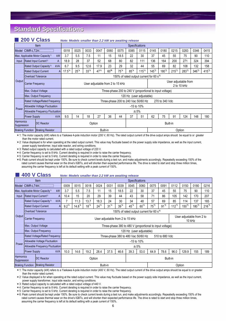
Standard SpecificationsStandard Specifications
148
346*5
13232490
0346
18091 124
415*5215*5 283*5
15882 108394200 27111055 75
0215 04150283Specifications
Built-inOptionDC ReactorHarmonics Suppression
7562513744362718149.5Power Supply kVA
Power
00255.5
Output
018001450115008500750060004700330018Model CIMR-LT2A
±5%Allowable Frequency Fluctuation-15 to 10%Allowable Voltage Fluctuation
Three-phase 200 to 240 Vac 50/60 Hz 270 to 340 VdcRated Voltage/Rated Frequency
Braking Function
120 Hz (user adjustable)Max. Output Frequency
OptionBuilt-inBraking Resistor
Three-phase 200 to 240 V (proportional to input voltage)Max. Output Voltage
User adjustable from2 to 10 kHzUser adjustable from 2 to 15 kHzCarrier Frequency
150% of rated output current for 60 s*6Overload Tolerance180*5145*5115*485*475*460*447*433*425*417.5*4Rated Output Current A
69554432292317.912.69.56.7Rated Output Capacity*3 kVA16413611182806852372818.9Rated Input Current*2 AInput4537302218.515117.53.7Max. Applicable Motor Capacity*1 kW
Item
189155
216*5180*516513720717011090
02160180SpecificationsItem
Option
Built-inOptionDC ReactorHarmonics Suppression
129.996.078.664.953.039.346.637.528.419.214.610.0Power Supply kVA
Power
Built-inBraking Resistor
±5%Allowable Frequency Fluctuation-15 to 10%Allowable Voltage Fluctuation
Three-phase 380 to 480 Vac 50/60 Hz 510 to 680 VdcRated Voltage/Rated Frequency
Braking Function
120 Hz (user adjustable)Max. Output Frequency Three-phase 380 to 480 V (proportional to input voltage)Max. Output Voltage
User adjustable from 2 to 10 kHzUser adjustable from 2 to 15 kHzCarrier Frequency
150% of rated output current for 60 s*6Overload Tolerance150*5112*591*575*560*445*439*431*424*418*414.8*49.2*4Rated Output Current A1148569574834302418.313.711.37Rated Output Capacity*3 kVA
Output
14210586715843443929201510.4Rated Input Current*2 AInput75554537302218.515117.55.53.7Max. Applicable Motor Capacity*1 kW
015001120091007500600045003900310024001800150009Model CIMR-LT4A
*1: The motor capacity (kW) refers to a Yaskawa 4-pole induction motor (200 V, 60 Hz). The rated output current of the drive output amps should be equal to or greaterthan the motor rated current.
*2: Value displayed is for when operating at the rated output current. This value may fluctuate based on the power supply side impedance, as well as the input current, power supply transformer, input side reactor, and wiring conditions.
*3: Rated output capacity is calculated with a rated output voltage of 220 V.*4: Carrier frequency is set to 8 kHz. Current derating is required in order to raise the carrier frequency. *5: Carrier frequency is set to 5 kHz. Current derating is required in order to raise the carrier frequency.*6: Peak current should be kept under 150%. Be sure to check current levels during a test run, and make adjustments accordingly. Repeatedly exceeding 150% of the
rated current causes thermal wear on the drive's IGBTs, and will shorten their expected performance life. The drive is rated to start and stop three million times, assuming the carrier frequency is left at its default setting with a peak current of 150%.
*1: The motor capacity (kW) refers to a Yaskawa 4-pole induction motor (400 V, 60 Hz). The rated output current of the drive output amps should be equal to or greaterthan the motor rated current.
*2: Value displayed is for when operating at the rated output current. This value may fluctuate based on the power supply side impedance, as well as the input current, power supply transformer, input side reactor, and wiring conditions.
*3: Rated output capacity is calculated with a rated output voltage of 440 V.*4: Carrier frequency is set to 8 kHz. Current derating is required in order to raise the carrier frequency. *5: Carrier frequency is set to 5 kHz. Current derating is required in order to raise the carrier frequency.*6: Peak current should be kept under 150%. Be sure to check current levels during a test run, and make adjustments accordingly. Repeatedly exceeding 150% of the
rated current causes thermal wear on the drive's IGBTs, and will shorten their expected performance life. The drive is rated to start and stop three million times, assuming the carrier frequency is left at its default setting with a peak current of 150%.
200 V Class Note: Models smaller than 2.2 kW are awaiting release
400 V Class Note: Models smaller than 2.2 kW are awaiting release

7
L1000A
±5%Torque Accuracy
-20 to 60 (short-term temperature during transportation)Storage Temperature95% RH or less (no condensation)Humidity-10 to 40 (open-chassis), -10 to 50 (NEMA Type 1)Ambient TemperatureIndoorsArea of Use
10 Hz to 20 Hz, 9.8 m/s2 max. 20 Hz to 55 Hz, 5.9 m/s2 max. ShockUp to 1000 metersAltitude
UL508C, EN61800-3, EN61800-5-1,EN954-1 Cat. 3, ISO13849-1 (Cat. 3, PLd), IEC/EN61508 SIL2Standards Compliant
Protection by electronic circuit*3Ground Fault ProtectionStall prevention during accelerationStall Prevention
IP00 open-chassis, NEMA Type 1 enclosure*4Protective Design
Charge LED remains lit until DC bus has fallen below approx. 50 VCharge LED
ThermistorHeatsink Overheat Protection
200 V class: Stops when DC bus exceeds approx. 190 V400 V class: Stops when DC bus exceeds approx. 380 VUndervoltage Protection
200 V class: Stops when DC bus exceeds approx. 410 V400 V class: Stops when DC bus exceeds approx. 820 VOvervoltage Protection
Drive stops after 60 s at 150% of rated output current *2Overload Protection
Drive stops when output current exceeds 200% of rated output currentMomentary Overcurrent Protection
ThermistorMotor Protection
Torque compensation at start (with or without sensors), Auto-Tuning (for motor and encoder offset), braking sequence, Feed Forward, Short Floor, Advanced Short Floor, Rescue Operation using back-up power supply, Light Load Direction Search, Removable Terminal Block with Parameter Backup, Direct Landing...
Main Control Functions
User-selected programs and V/f preset patterns possibleV/f CharacteristicsApproximately 125% when using a braking resistor optionBraking Torque0.00 to 6000.0 s (4 selectable combinations of independent acceleration and deceleration settings)Accel/Decel Time
All vector control modes allow separate settings in four quadrantsTorque Limit
10 Hz in Open Loop Vector Control (25±10), 50 Hz in Closed Loop Vector Control (25±10) (excludes temperature fluctuation when performing Rotational Auto-Tuning)Speed Response
±0.2% in Open Loop Vector Control (25±10)*1, ±0.02% in Closed Loop Vector Control (25±10)Speed Control Accuracy
1:40 (V/f Control) 1:1500 (Closed Loop Vector Control) 1:200 (Open Loop Vector Control) 1:1500 (Closed Loop Vector Control for PM)Speed Control Range
150% / 3 Hz (V/f Control) 200% / 0 r/min (Closed Loop Vector Control) 200% / 0.3 Hz (Open Loop Vector Control) 200% / 0 r/min (Closed Loop Vector Control for PM)Starting Torque
-10 to 10 V, 0 to 10 VFrequency Setting Resolution0.001 HzOutput Frequency Resolution
Digital reference: 0.01 HzAnalog reference: 0.03 Hz / 60 Hz (11 bit)Frequency Setting Resolution
Digital reference: within ±0.01% of the max. output frequency (-10 to +40)Analog reference: within ±0.1% of the max. output frequency (25±10)
Frequency Accuracy (Temperature Fluctuation)
0.01 to 120 HzFrequency Control Range
Use drive parameters to select from the following control modes:V/f Control, Open Loop Vector Control, Closed Loop Vector Control, Closed Loop Vector Control for PMControl Method
SpecificationItem
Note: Specifications regarding Open Loop Vector Control capabilities require Rotational Auto-Tuning.L1000 must be used in acceptable environmental conditions to ensure the expected performance life of all drive components.
*1: Speed control accuracy may vary slightly depending on installation conditions or motor used. Contact Yaskawa for details.*2: Overload protection may be triggered when operating for 60 s with 150% of the rated output current if the output frequency is less than 6 Hz.*3: Protection may not be provided under the following conditions as the motor windings are grounded internally during run:
・Low resistance to ground from the motor cable or terminal block.・Drive already has a short-circuit when the power is turned on.
*4: Removing the cover from a NEMA Type 1 model drive (models CIMR-LT2A0018 to 2A0075, CIMR-LT4A0009 to 4A0039) converts the enclosure rating to IP20.
Common Specifications
Contr
ol Ch
arac
terist
icsEn
viron
ment
Prote
ction
Fun
ction
s

8
DimensionsDimensions Enclosure Panel (NEMA Type 1)
Open-Chassis (IP00)
18.515117.55.53.7
Applicable Motor(kW)
Dimensions (mm)
9.7M6578158350335192197365220200758.7M6578-8-33519219735022000605.6M5575-8-28416018730018000474.0M5555-6-24812216726014000334.0M5555-6-24812216726014000253.5M5555-6-248122164260140
1
0018
Weight(kg)dt1D1H3H2H0H1W1DHW
Figure
ModelCIMR-LT2A
200 VClass
79M103.23.213012.568032533070545001809042M62.32.31107.5535260283550325
1
015075
400 V Class
110
5545373022
Applicable Motor(kW)
Dimensions (mm)
96M124.54.5130137733703508005000216
41M62.32.31107.5535260283550325011236M63.22.31057.5495260258510325009136M63.22.31057.5495260258510325007525M62.32.31007.5435220258450275006021M62.32.31007.53851952584002500045
Weight(kg)dt2t1D1H2H1W1DHW
Figure
ModelCIMR-LT4A
Figure 1
W1 4-d
1.5
W H2
H1 H
D D1t1
W1
W H2 H3
H1
H0 H
4-d
1.5
D D1 t1
Figure 1 Figure 2
W1 4-d
H1 H
t1W D
D1
t2
10 max. 10 max.H2
18.515117.55.53.7
Applicable Motor(kW)
Dimensions (mm)
8.3M6578-8-335192197350220200395.7M5575-8-28416018730018000315.4M5555-8-28416016730018000243.9M5555-6-24812216726014000183.9M5555-6-24812216726014000153.5M5555-6-248122164260140
1
0009
Weight(kg)dt1D1H3H2H0H1W1DHW
Figure
ModelCIMR-LT4A
400 VClass
80M103.23.213012.568032533070545002837576M103.23.213012.5680325330705450021555
98M124.54.513013773370350800500034690
1 38M62.32.31107.5535260283550325018045
200 VClass
110
373022
Applicable Motor(kW)
Dimensions (mm)
99M124.54.5130137733703508005000415
37M62.32.31107.5535260283550325014525M62.32.31007.5435220258450275011521M62.32.31007.53851952584002500085
Weight(kg)dt2t1D1H2H1W1DHW
Figure
ModelCIMR-LT2A

9
Watt Loss and Drive Watt Loss and Drive DeratingDerating
L1000A
Watt Loss Data
The drive can be operated at above the rated temperature, altitude, and default carrier frequency by derating the drive capacity.A drive with a rated output current of 10 A can be derated to having an output current of 8 A, thus allowing the drive to operate continuously at a higher temperature.
Derating as the carrier frequencyAs the carrier frequency of the drive is increased above the default setting, the drive’s rated output current must be derated according to Figure 1 to Figure 4.
Derating
2524 *1588 *11936 *1283 *10283751980 *1466 *11514 *1215 *1021555
3347 *1783 *12564 *1346 *1034690
1354 *1378 *1976 *1180 *1018045
200 VClass
91225066211501153072121151085008522
1122 *1306 *1816 *1145 *1014537
68122146075007518.5
110
15117.55.53.7
Applicable Motor (kW)
Carrier Frequency 8 kHz
3626 *2954 *22672 *2415 *20415
558163395600060410130280470047319105214330033287921942500251686710117.50018
Total Loss (W)Interior Unit Loss (W)Heatsink Loss (W)Rated Amps (A)Model
CIMR-LT2A
*1: These values assume the carrier frequency is set to 5 kHz. *2: These values assume the carrier frequency is set to 2 kHz.
Figure 1. CIMR-LT2A0018 to 2A0115
Drive rating80% of drive rating70% of drive rating
0 8 kHz 15 kHz
2A0018 to 2A0060
2A0075 to 2A0115
Figure 2. CIMR-LT2A0145 to 2A0415
Drive rating80% of drive rating
0 5 kHz 10 kHz
2A0145 to 2A0415
Figure 3. CIMR-LT4A0009 to 4A0091
Drive rating
60% of drive rating
0 8 kHz 15 kHz
4A0009 to 4A0091
Figure 4. CIMR-LT4A0112 to 4A0216
Drive rating
70% of drive rating
0 5 kHz 10 kHz
4A0112 to 4A0216
2313 *1541 *11771 *1180 *10180901920 *1580 *11340 *1150 *1015075
400 VClass
1022 *1299 *1723 *191 *1009145817 *1254 *1563 *175 *10075377012174846000603051817034945004522
1325 *1416 *1908 *1112 *1011255
50917933039003918.5
110
15117.55.53.7
Applicable Motor (kW)
Carrier Frequency 8 kHz
3075 *1715 *12360 *1216 *10216
403141263310031323115208240024247971501800182218613514.8001513061699.20009
Total Loss (W)Interior Unit Loss (W)Heatsink Loss (W)Rated Amps (A)Model
CIMR-LT4A

10
Standard Connection DiagramStandard Connection Diagram
FM
R/L1
L1000A
U/T1
Ground
MA
MB
MC
+2 +1 - B1 B2
JumperU X
DC reactor (option)
Fuse
S/L2
T/L3
r1s1t1
2MCCB
R
S
T
MCCB or ELCBMC
Three-phase power supply200 to 240 V50/60 Hz
Thermal relay trip contact (option)
Braking resistor (option)
Terminals -, +1, B1, B2 are for connecting options. Never connect power supply lines to these terminals.
Wiring sequence should shut off power to the drive when a fault output is triggered.
Main Circuit
V/T2
W/T3
M
M
U
V
W
FU
FV
FW
r1
s1
t1 Cooling fan
A+A-B+B-Z+Z-
SDNC
TB2CN3
IPIG
FE
SG
TB1
PG
a+a-b+b-z+z-
A track monitor
B track monitor
Z track monitor
IP12IP5IG
PG-X3
M1
M2
P1
C1P2
C2
AM
FM
AM
AC
0 V
E(G)
DM+DM-
+
+
-
-
Fault relay output250 Vac, max. 1 A30 Vdc, max. 1 A(min. 5 Vdc, 10 mA)Multi-function relay output(Brake control)250 Vac, max. 1 A30 Vdc, max. 1 A(min. 5 Vdc, 10 mA)
Analog monitor output 1(Output frequency)-10 to +10 V (2 mA)
Analog monitor output 2(Output current)-10 to +10 V (2 mA)
EDM (Safety Electronic Disable Monitor)
SA
MCON
MC
OFFTHRX2MCCBMC MB
SA
THRX
1 2
Braking resistor unit thermal relay trip contact
SA
TRX
MC MATRX
Fault relay contact
Forward run / Stop
Reverse run / Stop
S1
Separate transformer is required when running from a 400 V power supply to step the voltage down to 200 V.
S2
External fault S3
Fault reset S4
Multi-speed step 1 S5
Multi-speed step 2 S6
Multi-speed step 3 S7
Through-mode S8
SPSink/source
selection jumper
SC
SN 24 VCN5-CCN5-BCN5-A
Option board
connectors
Multi-function digital inputs
(default)
E(G)
+V Power supply +10.5 Vdc, max. 20 mAA1 Analog input 1
(Frequency reference bias)0 to +10 Vdc (20 kΩ)
A2 Analog input 2(Frequency reference bias)
0 to +10 V (20 kΩ) 4 to 20 mA (250 Ω)/0 to 20 mA (250 Ω)
AC
0 to +10 V
0 to +10 V
0 V
2 kΩ
Potentio-meter for frequency reference
Main frequency reference
-V (10.5 V 20 mA)
R+R-
Termination resistor (120Ω 1/2 W)
DIP switch S2
S+S-1G
MEMOBUSRS-422/485
max. 115.2 kbps
H1H2
HC
Wire jumper
Open
Safety relay / controller
Multi-function photocoupler output 1(Frequency output)48 Vdc, 2 to 50 mA
Multi-function photocoupler output 2(Not used)48 Vdc, 2 to 50 mA
Control Circuit
Safety switch
Safety Disable inputs
M3
M4
Multi-function relay output(Output contactor control)250 Vac, max. 1 A30 Vdc, max. 1 A(min. 5 Vdc, 10 mA)
M5
M6
Multi-function relay output(Drive ready)250 Vac, max. 1 A30 Vdc, max. 1 A(min. 5 Vdc, 10 mA)
shielded line twisted-pair shielded line
main circuit terminal control circuit terminal
*1
*2*3,*4
*5
*7
*6
*8
<9>
*9
*1: Remove the jumper between terminals +1 and +2 when installing a DC reactor option.*2: Models CIMR-LT2A0085 to 2A0415 and 4A0045 to 4A0216 come with a built-in DC reactor. *3: Disable protection for built-in braking transistor (L8-55 = 1) when using a regenerative converter, regenerative unit, or braking unit (and therefore not using the built-in braking transistor).*4: Drives using a braking resistor unit should wire a thermal relay so that the power supply is also shut off if overheat occurs.*5: Self-cooling motors do not require wiring that would be necessary with motors using a cooling fan.*6: A separate 24 V power supply is required to have the control circuit still operating while the power to the main circuit is shut off.*7: For control modes that do not use a motor speed feedback signal, PG option card wiring is not necessary.*8: Place jumpers to set the drive for sink or source (internal or external power supply). The default setting is for sink (internal power supply).*9: The maximum output current capacity for the +V and −V terminals on the control circuit is 20 mA. Never short terminals +V, −V, and AC, as this can cause erroneous operation or damage
the drive.*10: Enable the termination resistor in the last drive in a MEMOBUS/Modbus network by setting DIP switch S2 to the ON position.*11: The sink/source setting for the Safe Disable input is the same as with the sequence input. Jumper S3 has the drive set for an external power supply. When not using the Safe Disable input
feature, remove the jumper shorting the input and connect an external power supply.*12: Disconnect the wire jumper between HC - H1 and HC - H2 when utilizing the Safe Disable input.*13: Monitor outputs work with devices such as analog frequency meters, ammeters, voltmeters, and wattmeters. Do not use these outputs in a feedback loop.*14: Note that if the drive is set to trigger a fault output whenever the fault restart function is activated (L5-02 = 1), then a sequence to interrupt power when a fault occurs will result in shutting off
the power to the drive as the drive attempts to restart itself. The default setting for L5-02 is 0 (fault output active during restart attempt).*15: MA, MB, and MC must be used as fault outputs. They must be set up so that any interruption in the safety chain shuts off drive output.*16: Even though no fault is present conditions where the drive can not start can occur, e.g., when the digital operator is left in the Programming Mode. Use the "Drive Ready" output
(default set to terminals M5-M6) to interlock operation in such situations.
CIMR-LT2A0033: 200 V Class 7.5 kW
<9>
*10
*11
*12
*15
*16
*13
*14

11
L1000 and L1000 and YaskawaYaskawa PM MotorsPM Motors FlatFlat--type and basetype and base--mount motorsmount motors
Model Number KeyModel Number Key
L1000A
200 VClass
2A00601689.729P71681052A00601448.328P3144902A0047965.625P6096602A0047724.224P207245
900
2A0047966.226P2096602A0047724.624P607245
1000
L1000Motor
2A00752A0075
2A00602A00602A00332A00332A00472A00472A00332A00332A00332A00252A0025
CIMR-LT
1681120111681051449.229P214490
1688.128P11681051446.926P914490964.624P609660723.523P507245
750
1686.526P51681051445.625P614490963.723P709660722.822P807245
600
1444.224P214490962.822P809660722.122P107245
450
Motor Speed(r/min)
Motor Output(kW)
ModelSSE4-
Elevator Speed(m/min)
Weight(Kg)
400 VClass
4A00311681140111681054A0039192134013192120
4A00311449.249P2144904A0024966.246P2096604A0024724.644P607245
1000
4A00311688.148P11681054A00311446.946P9144904A0018964.344P3096604A0018723.243P207245
690
4A0015962.842P809660
4A00311689.749P71681054A00311448.348P3144904A0018965.645P6096604A0018724.244P207245
900
4A00314A00314A00184A0018
4A00244A00244A00184A00184A00184A0018
4A0015
1688.148P11681051446.946P914490964.644P309660723.543P207245
750
1686.546P51681051445.645P614490963.743P709660722.842P807245
600
1684.844P81681051444.244P214490
722.142P107245
450
CIMR- L T 2 A 0018 A A ADrive L1000 Series
JapanAAsiaT
RegionNo.3-phase, 200 V3-phase, 400 V
24
Voltage ClassNo.
Standard modelA
Customized SpecificationsNo. See chart above.
Current ClassNo.IP00NEMA Type 1
AF
Enclosure TypeNo.
StandardA
Environmental SpecificationsNo.
Design Revision Order
12
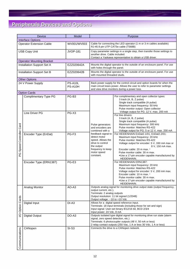
Peripherals Devices and OptionsPeripherals Devices and Options
For HEIDENHAIN ERN1387:Maximum input frequency: 20 kHzPulse monitor: Matches RS-422Voltage output for encoder: 5 V, 200 mA max.Encoder cable: 10 m max. *Pulse monitor cable: 30 m max.*Use a 17-pin encoder capable manufactured byHEIDENHAIN.
For HEIDENHAIN EnDat2.1/01, EnDat2.2/01:Maximum input frequency: 20 kHzPulse monitor: Matches RS-422Voltage output for encoder: 5 V, 330 mA max or
8 V, 150 mA max.Encoder cable: 20 m max. *Pulse monitor cable: 30 m max.*Use a 17-pin encoder capable manufactured byHEIDENHAIN.
For line drivers:3 track (A, B, Z pulse)Single track compatible (A pulse)Maximum input frequency: 300 kHzPulse monitor: Matches RS-422Voltage output for PG: 5 or 12 V, max. 200 mA
For complimentary and open collector types:3 track (A, B, Z pulse)Single track compatible (A pulse)Maximum input frequency: 50 kHzPulse monitor output: Open collectorVoltage output for PG: 12 V, max. 200 mA
PG-E3Encoder Type (ERN1387)
Outputs analog signal for monitoring drive output state (output frequency, output current, etc.).Terminals: 2 analog outputsOutput resolution: 11 bit signed (1/2048)Output voltage: −10 to +10 Vdc
AO-A3Analog Monitor
PG-F3Encoder Type (EnDat)
PG-X3Line Driver PG
Pulse generators and encoders are combined with a feedback signal to detect motor speed. Allows the drive to control the output frequency to keep motor speed constant.
PG-B3Complimentary Type PG
Interface Options
Connects the drive to a CANopen network.SI-S3CANopen
Outputs isolated type digital signal for monitoring drive run state (alarm signal, zero speed detection, etc.)Terminals: 6 photocoupler outputs (48 V, 50 mA or less)2 relay contact outputs (250 Vac, 1 A or less 30 Vdc, 1 A or less)
DO-A3Digital Output
Allows for a digital speed reference input.Terminals: 18 input terminals (including those for set and sign)Input signal: User-set binary 8/12/16 bit, BCD 2/3/4Input power: 24 Vdc, 8 mA
DI-A3Digital Input
Option Cards
Back power supply for the control circuit and option boards for when the main circuit loses power. Allows the user to refer to parameter settings and view drive monitors during a power loss.
PS-A10LPS-A10H
24 V Power SupplyOther Options
Mounts the digital operator to the outside of an enclosure panel. For use with mounted threaded studs.
EZZ020642BInstallation Support Set B
Mounts the digital operator to the outside of an enclosure panel. For use with holes through the panel.
EZZ020642AInstallation Support Set AOperator Mounting Bracket
Copy parameter settings in a single step, then transfer those settings to another drive. Cable included.Contact a Yaskawa representative to obtain a USB driver.
JVOP-181USB Copy Unit
Cable for connecting the LED operator (1 m or 3 m cables available)RJ-45 8 pin UTP CAT5e cable (T568B)
WV001/WV003Operator Extension Cable
PurposeModelDevice
PG S
peed
Con
trolle
r Car
dI/O
Opt
ion
Car
dsC
omm
unic
atio
ns
13
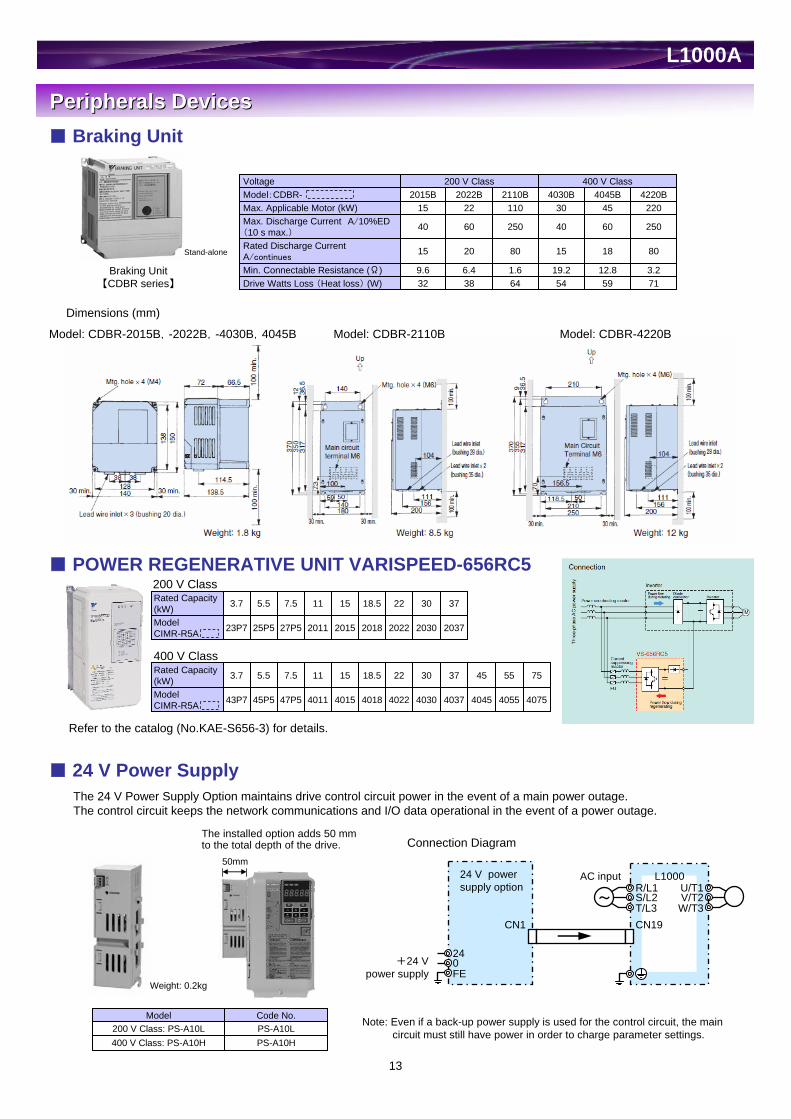
Peripherals DevicesPeripherals Devices Braking Unit
Model: CDBR-2015B,-2022B,-4030B,4045B Model: CDBR-2110B Model: CDBR-4220B
Stand-alone
Braking Unit【CDBR series】
3.212.819.21.66.49.6Min. Connectable Resistance (Ω)32
15
40
152015B
200 V Class
Drive Watts Loss (Heat loss) (W)
Rated Discharge CurrentA/continues
Max. Discharge Current A/10%ED(10 s max.)
Max. Applicable Motor (kW)Model:CDBR-Voltage
7159546438
8018158020
250604025060
2204530110224220B4045B4030B2110B2022B
400 V Class
Dimensions (mm)
POWER REGENERATIVE UNIT VARISPEED-656RC5
400 V Class
Refer to the catalog (No.KAE-S656-3) for details.
24 V Power SupplyThe 24 V Power Supply Option maintains drive control circuit power in the event of a main power outage. The control circuit keeps the network communications and I/O data operational in the event of a power outage.
The installed option adds 50 mm to the total depth of the drive.
Note: Even if a back-up power supply is used for the control circuit, the main circuit must still have power in order to charge parameter settings.
PS-A10HPS-A10LCode No.
400 V Class: PS-A10H200 V Class: PS-A10L
Model
Weight: 0.2kg
M~
24 V powersupply option
L1000AC inputR/L1S/L2T/L3
U/T1V/T2W/T3
CN19CN1
240FE
+24 Vpower supply
Connection Diagram
ModelCIMR-R5A 2018
18.5
2015
15
2011
11
27P5
7.5
25P5
5.5
23P7
3.7
2022
22Rated Capacity(kW)
20372030
3730
ModelCIMR-R5A 4018
18.5
4015
15
4011
11
47P5
7.5
45P5
5.5
43P7
3.7
4022
22Rated Capacity(kW)
40754055404540374030
7555453730
200 V Class
L1000A
50mm

14
Peripherals DevicesPeripherals Devices DC Reactor (UZDA-B for DC circuit)
Base device selection on motor capacity.
Lead Wire Type
*Cable: Indoor PVC(75), ambient temperature 45, 3 lines max.
Connection Diagram
L1000
DC reactor
R/L1S/L2T/L3
U/T1V/T2W/T3
MRST
XU
+2 +1Circuit breaker
Note: Remove jumper between +1 and +2, and wire as shownin the diagram.
Note: Reactor recommended for power supplies larger than 600 kVA.
Reactor unnecessary
Reactor required
Drive Capacity (kVA)
4000
600
060 400
2.2 5.5182M5M418556076368086
1
X0100493181.5
200 VClass
Built-in22~1106.5
4.9
3.2
Weight(kg)
45
29
22
WattLoss(W)
25
26
26
K
80
100
80
H
M6
M6
M6
φ1
G
M8
M8
M6
φ2
117
93
93
Z
52.5
56
46
Y1
3064105105X0100510.572117.5
86490105X0100501365.53.7
120
Y2
133
X
Dimensions (mm)
3086X0101760.49018.515
Wire*
Gauge(mm2)B
FigureInductance(mH)
Current(A) Code No.
MotorCapacity
(kW)
2.22111M4328060902X010053115.7
1.5
400 VClass
Built-in22~1106
4
3.2
2
Weight(kg)
42
26
27
16
WattLoss(W)
25
26
26
18
K
90
90
80
55
H
M6
M6
M6
M4
φ1
G
M6
M6
M5
M5
φ2
100
93
93
76
Z
57.5
51
46
36
Y1
86495105X0100561.933117.5
5.56490105X0100553.6235.5
2608086
1
X0100546.3123.7
125
Y2
115
X
Dimensions (mm)
1472X0101771.34718.515
Wire*
Gauge(mm2)B
FigureInductance(mH)
Current(A) Code No.
MotorCapacity
(kW)
Dimensions (mm)
Pow
er S
uppl
y C
apac
ity (k
VA
)
Figure 1 Figure 2

15
Fuse and Fuse HolderInstall a fuse to the drive input terminals to prevent damage in case a fault occurs.Refer to the instruction manual for information on UL-approved components.
200 VClass
Fuse HolderFuse
*
CM-2A
CM-1A
Model
CR2L-4000145CR2L-3500115
CR2L-2250060CR2L-1750047CR2L-1500033 1CR2L-1250025
CR2LS-10000180011 1
3
CR2LS-500008
CS5F-800
CR2L-600
CR2L-450
CR2L-300CR2L-260
Model
04150346028302150180
00850075
ModelCIMR-LT2A Qty. Qty.
*Manufacture does not recommended a specific fuse holder for this fuse.Contact the manufacture for information on fuse dimensions.
CR6L-15000310039
400 VClass
Fuse HolderFuse
*
CMS-5
CMS-4
Model
0075CR6L-2500060
CR6L-10000240018
1
CR6L-75001500090006 1
3
CR6L-500005
CS5F-600
CR6L-400CR6L-350CR6L-300
CR6L-200
Model
02160180015001120091
0045
ModelCIMR-LT4A Qty. Qty.
【Fuji Electric FA Components & System Co., Ltd】
Terminal Type
M6
M6
M6
M4
φ1
M6
M6
M4
M4
φ2
G
25
26
26
18
K
80
100
80
55
H
86
64
64
60
B
160
135
129
101
Z
52.5
56
46
36
Y1
147.5
124
94
84
Y2
133
105
105
86
X
Dimensions (mm)
2.2 182
1
300-027-1313181.5
200 VClass
6.5
4.9
3.2
Weight(kg)
44
29
22
WattLoss(W)
300-027-1330.572117.5
300-027-1321365.53.7
300-027-1390.49018.515
FigureInductance(mH)
Current(A) Code No.
MotorCapacity
(kW)
162M4M4185560101368486
1
300-027-1366.312
M6
M6
M6
M4
φ1
M5
M4
M4
M4
φ2
32
G
25
26
26
K
90
90
80
H
72
64
64
80
B
136
129
118
88
Z
57.5
51
46
Y1
142.5
109
104
Y2
115
105
105
90
X
Dimensions (mm)
2.21112300-027-135115.7
1.5
400 VClass
5
4
3.2
Weight(kg)
42
26
27
WattLoss(W)
300-027-1381.933117.5
300-027-1373.6235.53.7
300-027-1401.34718.515
FigureInductance(mH)
Current(A) Code No.
MotorCapacity
(kW)
Dimensions (mm)
L1000A
Figure 1 Figure 2
z

16
L1000A
DRIVE CENTER (INVERTER PLANT)2-13-1, Nishimiyaichi, Yukuhashi, Fukuoka, 824-8511, JapanPhone: 81-930-25-3844 Fax: 81-930-25-4369http://www.yaskawa.co.jp
YASKAWA ELECTRIC CORPORATIONNew Pier Takeshiba South Tower, 1-16-1, Kaigan, Minatoku, Tokyo, 105-6891, JapanPhone: 81-3-5402-4502 Fax: 81-3-5402-4580http://www.yaskawa.co.jp
YASKAWA AMERICA, INC.2121 Norman Drive South, Waukegan, IL 60085, U.S.A.Phone: (800) YASKAWA (927-5292) or 1-847-887-7000 Fax: 1-847-887-7310http://www.yaskawa.com
YASKAWA ELÉTRICO DO BRASIL LTDA.Avenda Fagundes Filho, 620 Bairro Saude, São Paulo, SP04304-000, BrasilPhone: 55-11-3585-1100 Fax: 55-11-5581-8795http://www.yaskawa.com.br
YASKAWA EUROPE GmbHHauptstrasse 185, 65760 Eschborn, GermanyPhone: 49-6196-569-300 Fax: 49-6196-569-398http://www.yaskawa.eu.com
YASKAWA ELECTRIC UK LTD.1 Hunt Hill Orchardton Woods, Cumbernauld, G68 9LF, United KingdomPhone: 44-1236-735000 Fax: 44-1236-458182http://www.yaskawa.co.uk
YASKAWA ELECTRIC KOREA CORPORATION7F, Doore Bldg. 24, Yeoido-dong, Yeungdungpo-gu, Seoul, 150-877, KoreaPhone: 82-2-784-7844 Fax: 82-2-784-8495http://www.yaskawa.co.kr
YASKAWA ELECTRIC (SINGAPORE) PTE. LTD.151 Lorong Chuan, #04-01, New Tech Park, 556741, SingaporePhone: 65-6282-3003 Fax: 65-6289-3003http://www.yaskawa.com.sg
YASKAWA ELECTRIC (SHANGHAI) CO., LTD.No. 18 Xizang Zhong Road, Room 17F, Harbour Ring Plaza, Shanghai, 200001, ChinaPhone: 86-21-5385-2200 Fax: 86-21-5385-3299http://www.yaskawa.com.cn
YASKAWA ELECTRIC (SHANGHAI) CO., LTD. BEIJING OFFICERoom 1011, Tower W3 Oriental Plaza, No. 1 East Chang An Ave.,Dong Cheng District, Beijing, 100738, ChinaPhone: 86-10-8518-4086 Fax: 86-10-8518-4082
YASKAWA ELECTRIC TAIWAN CORPORATION9F, 16, Nanking E. Rd., Sec. 3, Taipei, 104, TaiwanPhone: 886-2-2502-5003 Fax: 886-2-2505-1280
YASKAWA ELECTRIC CORPORATION
LITERATURE No.EZZ021066 8Published in Japan August 2010
In the event that the end user of this product is to be the military and said product is to beemployed in any weapons systems or the manufacture thereof, the export will fall underthe relevant regulations as stipulated in the Foreign Exchange and Foreign TradeRegulations. Therefore, be sure to follow all procedures and submit all relevantdocumentation according to any and all rules, regulations and laws that may apply.Specifications are subject to change without noticefor ongoing product modifications and improvements.
© 2009 YASKAWA ELECTRIC CORPORATION. All rights reserved.