Embed Size (px)
Citation preview

HYFIRE® 6.6 SERIES OF ELECTRONIC IGNITION CONTROL
HYFIRE® 6.6 IGNITION SYSTEM PART NO. 686M
FOR APPLICATIONS TRIGGERED BY POINTS, MALLORY ELECTRONIC IGNITION DISTRIBUTOR (ALL MODELS), ORIGINAL EQUIPMENT ELECTRONIC IGNITION AMPLIFIERS AND MAGNETIC TRIGGERPULSES (MAGNETIC PICKUP DISTRIBUTOR OR CRANK TRIGGER IGNITION). OPTIONAL ADAPTERSARE AVAILABLE FOR EASY CONNECTION TO EARLY MODEL DELCO/GM HEI SYSTEMS, LATE MODELGM HEI/EST SYSTEMS, FORD TFI SYSTEMS, AND OEM MAGNETIC PICKUP (NON-COMPUTER; FORDDURASPARK, GM HEI AND MOPAR/CHRYSLER ELECTRONIC SYSTEMS).
NOTE: MALLORY HYFIRE® 6.6 ELECTRONIC IGNITION CONTROLS ARE NOT COMPATIBLE WITH DISTRIBUTORLESS SYSTEMS OR POSITIVE GROUND APPLICATIONS. THE RPM LIMITERS IN THEHYFIRE® 6.6 (PART NO. 686M) WILL NOT WORK PROPERLY WITH ODD-FIRE OR SEMI-EVEN FIRE V6APPLICATIONS.
CONTENTS
General Information 2Ignition Ballast Resistor/Loom Resistance Wire 2Standard Ignition Bypass (Bypass Connector) 2Ignition Coils 2Fuel Injection 2Spark Plug Wires 2Spark Plug Gaps 2Electric Welding 2Mounting Procedure 2Mounting to a Flat Surface Without Brackets 2Mounting to a Flat or Uneven Surface Using Brackets 2Mounting to a Flat Surface with Shock Mounts 2Wiring Procedure 3Wiring Method using Adapters and Harnesses 3GM HEI Systems/coil-in-cap with OEM module) 4Late Model GM HEI/EST Systems (external coil) 4Ford TFI Systems 4
Ford DuraSpark Systems (non-computer type,without module) 5
Early Model GM HEI Systems (non-computer type,without module) 5
FORM 1486M 03/05
Mopar/Chrysler Corp. Electronic Systems(non-computer type, without module) 7
Wiring Method Without Adapters 7
Mallory Electronic Ignition, UNILITE® Distributors,Magnetic Breakerless Distributors or ElectronicAdvance Distributors (3-wire/red, brown, green) 7
For OEM Electronic Systems with modules/amplifiers(Chrysler, Ford, and import) 7
Magnetic Pickup Trigger Pulses (magneticpickup distributors or crank trigger ignition) 8
HYFIRE® 6.6 Ignition System Features 11
Bypass Connector 11
INSTALLATION INSTRUCTIONS®
1MALLORY IGNITION www.malloryracing.com
1 HYFIRE® 6.6 Electronic Ignition Control - Part No. 686M1 Ignition Control Harness1 Universal Installation Hardware Kit1 Hand Held Controller
PARTS INCLUDED IN THIS KIT:
WARNING: USE ONLY SUPPRESSION CORE STYLE SPARK PLUG WIRES WITH THE HYFIRE® 6.6 IGNITION CONTROL.
KEEP ALL IGNITION SYSTEM WIRES AS FAR FROM SPARK PLUG WIRES AS POSSIBLE.
GENERAL INFORMATIONThe HYFIRE®6.6 Ignition System Part Nos. 686M arenot for marine use.The RPM limiters in the HYFIRE® 6.6 is not recommendedas an engine speed governor. The use of the RPM limitersis not recommended for applications equipped with a catalytic converter. Similarly, forcing engine RPM past theRPM limiter continuously for long sustained intervals cancause fuel build up in the exhaust system that mayadversely affect your application. The RPM limiting systemswill not work properly with odd-fire V6 applications.
Ignition Ballast Resistor / Loom Resistance WireThe performance of the HYFIRE® 6.6 is not affected by the presence of the factory ignition resistors or ignition ballast resistors in the wire from the ignition switch.
Standard Ignition Bypass (Bypass Connector)The Bypass Connector (supplied) fits into the IgnitionControl Harness to convert back to standard ignition. If you use the Bypass Connector, use ignition ballast resistors designed for your vehicle’s distributor and coil(see diagrams for more information). This bypass methoddoes not work with magnetic pickup distributor or cranktrigger ignition. Racing Applications: It is not necessary toinstall ignition ballast resistors. However, do not use theBypass Connector until the ignition ballast resistors areinstalled in the wire from the ignition switch.
Ignition CoilsThe HYFIRE® 6.6 Electronic Ignition Controls are designedto work with most original equipment ignition coils. Foroptimum performance use the Mallory PROMASTER E CoilPart Number 30440 (Up to 7,500 RPM), Part No. 30625 (Upto 10,000 RPM), PROMASTER® Coil Part No. 29440 (up to7,500 RPM) or Part No. 29625 (up to 10,000 RPM).
Fuel InjectionSome fuel injection systems need a voltage spike signalfrom the ignition coil before they will operate properly. This signal changes once HYFIRE® 6.6 Electronic IgnitionControls are installed. The Mallory Fuel Injection andTachometer Adapters Part Nos. 29074 and 29078 supplythe proper signal to the vehicle computer to operate thefuel injection system. Installation procedure and diagramsare supplied with these adapters.
Spark Plug WiresYOU MUST USE suppression type (carbon core, spiralcore, suppression core) spark plug wire. We recommendspiral core ignition wire, such as Mallory PROSIDEWINDER® Ignition Wire. Suppression type spark plugwires prevent false triggering and possible premature ignition or accessory failures. DO NOT USE solid core (coppercore; stainless steel core) spark plug wire with any electronic ignition system or accessory.
Spark Plug GapsFor street applications, use your engine manufacturer’sspecifications. For racing applications, start with yourengine manufacturer’s specifications, then experiment with, and closely monitor, various gaps to achieve maximum performance.
Electric WeldingUnplug the Ignition Control Harness from the HYFIRE® 6.6Electronic Ignition Control and unplug any distributor harnesses (if possible) before any welding is done on thevehicle.
External RPM LimitersMallory Proportional RPM Limiter Part Nos. 641-4, 641-6,641-8, 642, 643 and 644 WILL NOT function with theHYFIRE® 6.6 Electronic Ignition Controls.
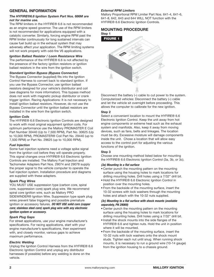
MOUNTING PROCEDUREStep 1
Disconnect the battery (–) cable to cut power to the system.Computerized vehicles: Disconnect the battery (–) cableand let the vehicle sit overnight before proceeding. Thisallows the computer to calibrate for the new ignition.
Step 2Select a convenient location to mount the HYFIRE® 6.6Electronic Ignition Control. Keep the unit away from hotengine components or extreme heat such as the exhaustsystem and manifolds. Also, keep it away from movingdevices, such as fans, belts and linkages. The locationmust be dry. Excessive moisture will damage componentsinside the unit. Chose a location that will allow easyaccess to the control port for adjusting the various functions of the ignition.
Step 3Choose one mounting method listed below for mountingthe HYFIRE® 6.6 Electronic Ignition Control (3a, 3b, or 3c).
(3a) Mounting to a flat surface• Center punch the mounting pattern on the mounting
surface using the housing holes to mark locations fordrilling mounting holes. Drill holes using a 7/32” drill bit.
• Hold the HYFIRE® 6.6 Electronic Ignition Control in position over the mounting holes.
• From the backside of the mounting surface, insert the 10-32 screws with lock washers through the mountingholes and attach with the 10-32 nuts supplied.
(3c) Mounting to a flat surface with shock mounts (available separately, PN 29069)• Center punch the mounting pattern on the mounting
surface using the housing holes to mark locations fordrilling mounting holes. Drill holes using a 7/32” drill bit.
• Install the shock mounts into the side flanges of theHYFIRE® 6.6 and tighten nuts. Hold the unit in positionwhere it will be mounted.
• From the backside of the mounting surface, insert the 10-32 nuts with lock washers onto the shock mountstuds. Tighten each nut until snug. When running shockmounts, it is necessary to run a ground wire (10-14 gauge)from the ignition housing to a chassis ground.
®
FIGURE 1
2 www.malloryracing.com MALLORY IGNITION
BLA
BRO
FIGURE 3
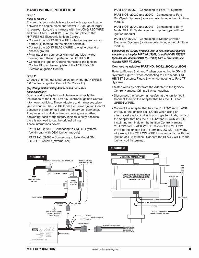
BASIC WIRING PROCEDUREStep 1Refer to Figure 2Ensure that your vehicle is equipped with a ground cablebetween the engine block and firewall (10 gauge or larger is required). Locate the harness with the LONG RED WIREand one LONG BLACK WIRE at the end plate of theHYFIRE® 6.6 Electronic Ignition Control.• Connect the LONG RED WIRE to the battery (+) post or
battery (+) terminal on the starter solenoid.• Connect the LONG BLACK WIRE to engine ground or
chassis ground.• Plug into 2-pin connector with red and black wires
coming from the end plate on the HYFIRE® 6.6.• Connect the Ignition Control Harness to the Ignition
Control Plug at the end plate of the HYFIRE® 6.6Electronic Ignition Control.
Step 2Choose one method listed below for wiring the HYFIRE®6.6 Electronic Ignition Control (2a, 2b, or 2c)
(2a) Wiring method using Adapters and Harnesses (sold separately)Special wiring Adapters and Harnesses simplify the installation of the HYFIRE® 6.6 Electronic Ignition Controlinto newer vehicles. These adapters and harnesses allowyou to connect the HYFIRE® 6.6 Electronic Ignition Controlbetween the ignition coil and the factory coil connector.They reduce installation time and wiring errors. Also, converting back to the factory ignition is easy becausethere is no need to cut the original wiring. These instructions cover:
PART NO. 29042 – Connecting to GM HEI Systems (coil-in-cap, with OEM ignition module)
PART NO. 29068 – Connecting to Late Model GMHEI/EST Systems (external coil)
PART NO. 29062 – Connecting to Ford TFI Systems.
PART NOS. 29039 and 29040 – Connecting to FordDuraSpark Systems (non-computer type, without ignitionmodule).
PART NOS. 29040 and 29043 – Connecting to EarlyModel GM HEI Systems (non-computer type, without ignition module)
PART NO. 29040 – Connecting to Mopar/ChryslerElectronic Systems (non-computer type, without ignitionmodule).
Connecting to: GM HEI Systems (coil-in-cap, with OEM ignitionmodule), use Adapter PART NO. 29042; Late Model GM HEI/ESTSystems, use Adapter PART NO. 29068; Ford TFI Systems, useAdapter PART NO. 29062.
Connecting Adapter PART NO. 29042, 29062 or 29068
Refer to Figures 3, 4, and 7 when connecting to GM HEISystems; Figure 5 when connecting to Late Model GMHEI/EST Systems; Figure 6 when connecting to Ford TFISystems.
• Match wires by color from the Adapter to the IgnitionControl Harness. Crimp all wires together.
• Disconnect the factory harness(es) at the ignition coil.Connect them to the Adapter that has the RED andGREEN WIRES.
• Connect the Adapter that has the YELLOW and BLACKWIRES to the ignition coil. NOTE: When using an aftermarket ignition coil with post type terminals, discardthe Adapter that has the YELLOW and BLACK WIRES.Install ring terminals on the Ignition Control Harness YELLOW and BLACK WIRES. Connect the YELLOWWIRE to the ignition coil (+) terminal. DO NOT allow anywire except the YELLOW WIRE to make contact with theignition coil (+) terminal. Connect the BLACK WIRE to theignition coil (–) terminal.
3MALLORY IGNITION www.malloryracing.com
FIGURE 2
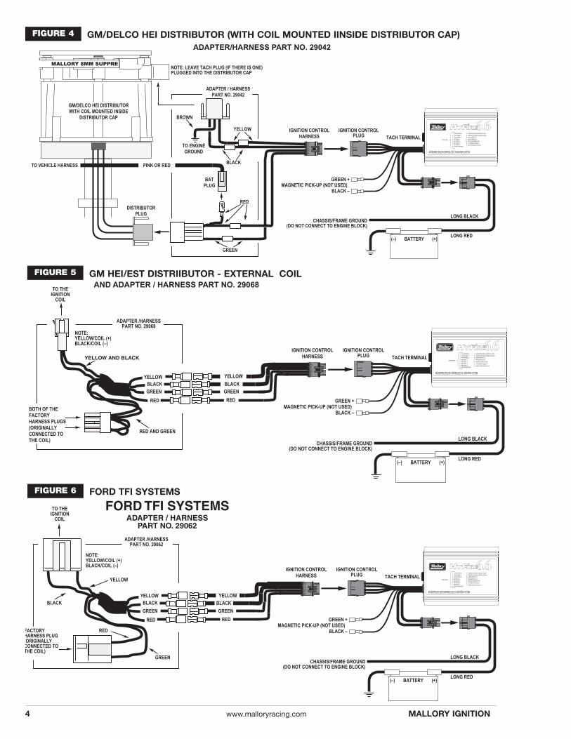
FIGURE 6 FORD TFI SYSTEMS
®
FIGURE 4 GM/DELCO HEI DISTRIBUTOR (WITH COIL MOUNTED IINSIDE DISTRIBUTOR CAP)
FIGURE 5 GM HEI/EST DISTRIIBUTOR - EXTERNAL COIL
4 www.malloryracing.com MALLORY IGNITION
5MALLORY IGNITION www.malloryracing.com
®
FIGURE 7
21
+
®
FIGURE 8
®
®
FIGURE 10
FIGURE 11
6 www.malloryracing.com MALLORY IGNITION
®
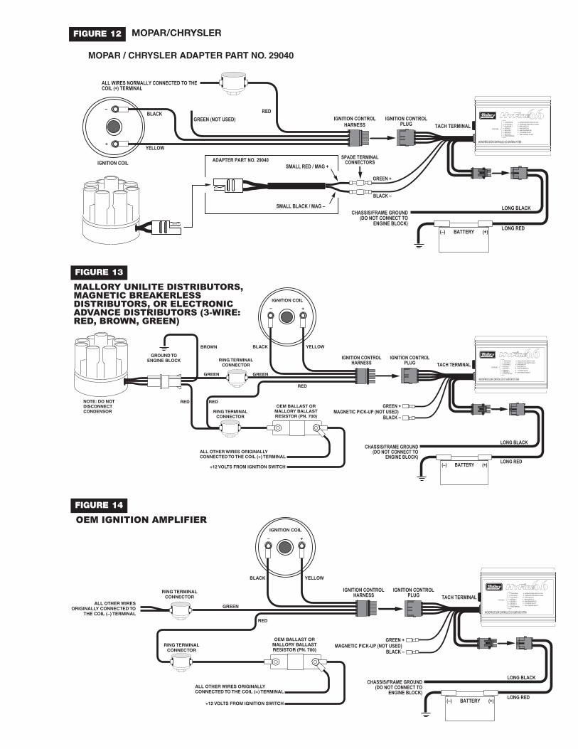
FIGURE 12 MOPAR/CHRYSLER
®
®
FIGURE 13
FIGURE 14
8
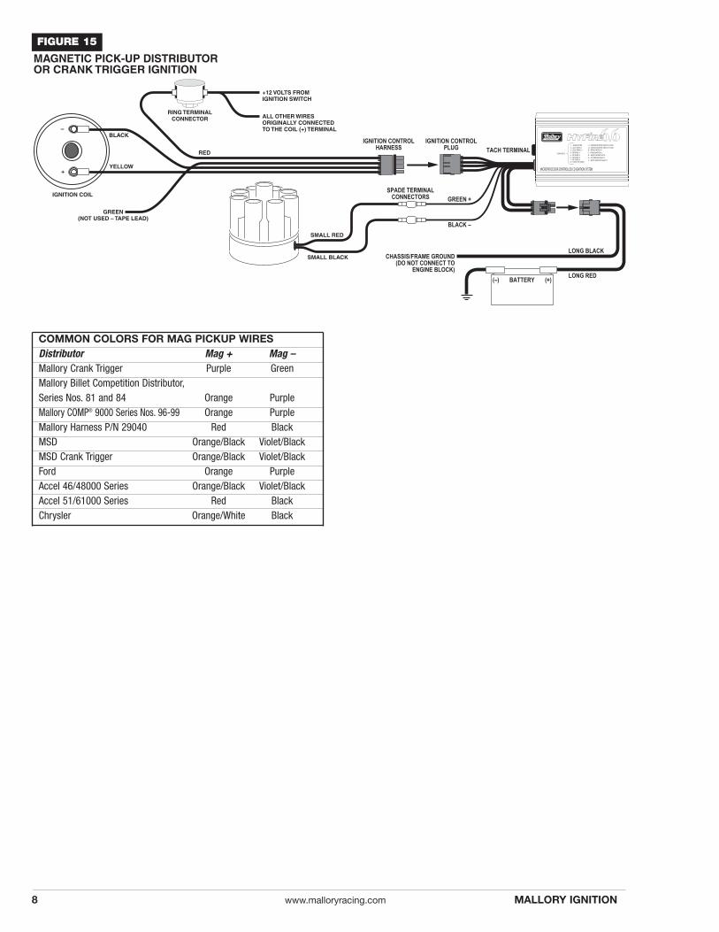
FIGURE 15
www.malloryracing.com MALLORY IGNITION
COMMON COLORS FOR MAG PICKUP WIRESDistributor Mag + Mag –Mallory Crank Trigger Purple GreenMallory Billet Competition Distributor,Series Nos. 81 and 84 Orange PurpleMallory COMP® 9000 Series Nos. 96-99 Orange PurpleMallory Harness P/N 29040 Red BlackMSD Orange/Black Violet/BlackMSD Crank Trigger Orange/Black Violet/BlackFord Orange PurpleAccel 46/48000 Series Orange/Black Violet/BlackAccel 51/61000 Series Red BlackChrysler Orange/White Black
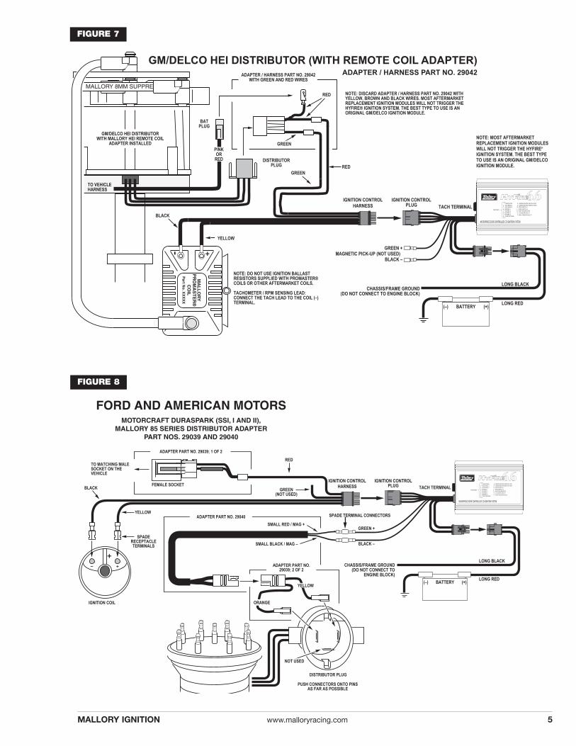
Connecting to Ford DuraSpark Systems (non-computer type) usingAdapter PART NO. 29039 and Harness PART NO. 29040 for OEMmagnetic pickupRefer to Figure 8 while performing the following steps.
Connecting Adapter PART NO. 29039:
• Disconnect all connectors at the ignition module, ignitioncoil and distributor. Remove the ignition module. Removethe distributor and coil harnesses.
• Connect the Adapter ORANGE WIRE to the distributorplug’s ORANGE WIRE.
• Connect the Adapter YELLOW WIRE to the distributorplug’s PURPLE WIRE.
• Connect the other Adapter female socket to the vehicle’smatching male socket. (The matching male socket wasoriginally connected the ignition module.)
Connecting the Harness PART NO. 29040:
• Connect the HYFIRE® 6.6 Electronic Ignition Control’sSMALL GREEN WIRE to the Harness RED WIRE.
• Connect the HYFIRE® 6.6 Electronic Ignition Control’sSMALL BLACK WIRE to the Harness BLACK WIRE.
• Connect the mating plug of the Harness to the matingplug of the Adapter Part No. 29039 from the distributor.
Connecting the Ignition Control Harness:
• Route the Ignition Control Harness to the coil so that itswires do not make contact with extreme heat, sharpobjects or moving devises such as fans, belts and linkages.
• Crimp the Ignition Control Harness RED WIRE to the sliceconnector on the Adapter Part No. 29039 female socket.
• Crimp a spade receptacle terminal on the Ignition ControlHarness YELLOW WIRE. Connect the YELLOW WIRE tothe ignition coil (+) terminal. DO NOT allow any wireexcept the YELLOW WIRE to make contact with the coil(+) terminal.
• Crimp a spade receptacle terminal on the Ignition ControlHarness BLACK WIRE. Connect the BLACK WIRE to theignition coil (–) terminal.
• NOTE: Do not connect the GREEN WIRE of the IgnitionControl Harness to anything. Tape the end of the wire toinsulate it.
• Go to Step 3, page 11.
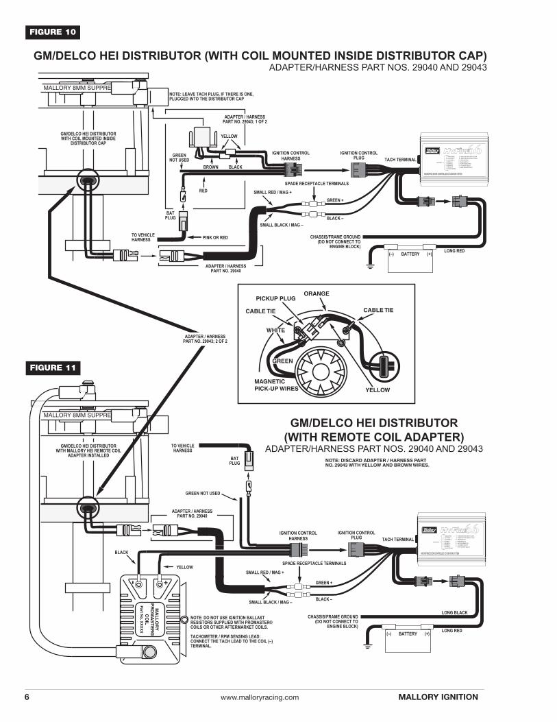
Connecting to Early Model GM HEI Systems (non-computer type)using Adapter PART NO. 29043 and Harness PART NO. 29040 forOEM magnetic pick-up. Refer to Figures 11 and 12 while performing the following steps.
Connecting Adapter PART NO. 29043:
For coil-in-cap distributors only
• Disconnect the (RED or PINK) BAT PLUG/wire from thedistributor cap.
• Disconnect the tachometer wire from the TACH terminalon the distributor cap.
• Disconnect the distributor plug from the distributor cap.For coil-in-cap distributors and external coil
• Remove the distributor cap.
• Disconnect the pickup plug from the ignition module.
• Remove the ignition module, radio noise filter/capacitorand distributor plug harness.
• Slide the Adapter ORANGE and YELLOW WIRES throughthe grommet (supplied).
• Connect the Adapter ORANGE WIRE to the pickup plug’sWHITE WIRE.
• Connect the Adapter YELLOW WIRE to the pickup plug’sGREEN WIRE.
• Position the grommet into the slot on the edge of the distributor housing. Use cable ties and 8-32 screws tohold wires in place.
• Install the distributor cap.
Connecting the Harness PART NO. 29040:
• Connect the HYFIRE® 6.6 Electronic Ignition Control’sSMALL GREEN WIRE to the Harness RED WIRE.
• Connect the HYFIRE® 6.6 Electronic Ignition Control’sSMALL BLACK WIRE to the Harness BLACK WIRE.
• Connect the mating plug of the Harness to the matingplug of the Adapter Part No. 29043 from the distributor.
Connecting the Ignition Control Harness:
• Route the Ignition Control Harness to the coil so that itswires do not make contact with extreme heat, sharpobjects or moving devises such as fans, belts and linkages.
• Crimp a spade terminal on the Ignition Control HarnessRED WIRE.
9MALLORY IGNITION www.malloryracing.com
10 www.malloryracing.com MALLORY IGNITION
Connecting the Ignition Control Harness:
• Route the Ignition Control Harness to the ignition coil sothat its wires do not make contact with extreme heat,sharp objects or moving devices such as fans, belts andlinkages.
• Connect the RED WIRE to the terminal on the ignition ballast resistor that previously had the DARK GREEN/REDWIRE connected to it (or to a 12-volt wire from the ignitionswitch). NOTE: The RED WIRE must get voltage when theignition switch is in the START and RUN positions.
• Connect the YELLOW WIRE to the ignition coil (+) terminal. DO NOT allow any wire except the YELLOWWIRE to make contact with the ignition coil (+) terminal.
• Connect the BLACK WIRE to the ignition coil (–) terminal.
• DO NOT connect the GREEN WIRE of the Ignition ControlHarness to anything. Tape the end of it to insulate it.
• Go to Step 3, page 11.
(2b) Wiring method without adapters; Mallory ElectronicIgnitions (three wire/red, brown, green); OEM electronicignition amplifiers.
Refer to: Figure 13 for Mallory UNILITE® Distributors, MagneticBreakerless Distributors or Electronic Advance Distributors (threewire/red, brown, green); Figure 14 for OEM electronic ignitionamplifiers
Connecting the Ignition Control Harness
• Route the Ignition Control Harness to the ignition coil sothat its wires do not make contact with extreme heat,sharp objects or moving devises such as fans, belts andlinkages.
• Disconnect ALL wires located on the ignition coil (+) terminal. These include the wires from the ignitionswitch/ignition ballast resistor, start/ignition bypass andany other wires normally connected to the ignition coil (+)terminal. Connect these wires to the RED WIRE. NOTE:The RED WIRE must get voltage when the ignition switchis in the START and RUN positions. If you are using aMallory Electronic Ignition, connect its BROWN WIRE toengine ground and add its RED WIRE to the IgnitionControl Harness RED WIRE. Use Ring TerminalConnectors to join wires together (See page 2 - IgnitionBallast Resistor / Loom Resistance Wire and StandardIgnition Bypass).
• Similarly, disconnect ALL wires located on the ignition coil(–) terminal. Connect these wires to the GREEN WIRE. Ifyou are using a Mallory Electronic Ignition, add its GREENWIRE to the Ignition Control Harness GREEN WIRE. UseRing Terminal Connectors to join wires together.
• Connect the YELLOW WIRE to the ignition coil (+) terminal. DO NOT allow any wire except the YELLOWWIRE to make contact with the ignition coil (+) terminal.
• Connect the BLACK WIRE to the ignition coil (–) terminal.
• Go to Step 3, page 11.
For coil-in-cap distributors onlyRefer to Figure 10 while performing the following steps.
• Connect the BAT PLUG/wire to the RED WIRE.
• Crimp the YELLOW WIRE to the YELLOW WIRE of theAdapter Part No. 29043 3-pin connector.
• Crimp the BLACK WIRE to the BROWN WIRE of theAdapter Part No. 29043 3-pin connector.
• Plug the Adapter Part No. 29043 3-pin connector into thedistributor cap.
• Note: DO NOT connect the GREEN WIRE of the IgnitionControl Harness to anything. Tape the end of it to insulateit.
• Go to Step 3, page 11.
For external coil only
Refer to Figure 11 while performing the following steps.(Replace the words “spade receptacle terminal” with “ring termi-nal” when aftermarket coils with post type terminals are used.)
• Disconnect the BAT wire from the ignition coil BAT/(+) terminal. Connect the BAT wire to the RED WIRE.
• Disconnect the tachometer wire from the ignition coilTACH/(–) terminal.
• Crimp a spade receptacle terminal on the Ignition ControlHarness YELLOW WIRE. Connect the YELLOW WIRE tothe ignition coil BAT/(+) terminal. DO NOT allow any wireexcept the YELLOW WIRE to make contact with the ignition coil BAT/(+) terminal.
• Crimp a spade receptacle terminal on the Ignition ControlHarness BLACK WIRE. Connect the BLACK WIRE to theignition coil BAT/(–) terminal.
• Discard the adapter plug with the yellow and brown wiresfrom the Adapter PART NO. 29043. It is not used onexternal ignition coil HEI systems.
• Note: DO NOT connect the GREEN WIRE of the IgnitionControl Harness to anything. Tape the end of it to insulateit.
• Go to Step 3, page 11.
Connecting to Mopar/Chrysler Electronic Systems (non-computertype) using Harness PART NO. 29040 for OEM magnetic pickup
Refer to Figure 12 while performing the following steps.
• Disconnect all connectors at the ignition module, ignitioncoil and distributor. Remove the ignition module. Takenotice of a DARK GREEN/RED WIRE connected to theignition ballast resistor. Remove the distributor and coilharnesses.
Connecting the Harness PART NO. 29040:
• Connect the HYFIRE® 6.6 Electronic Ignition Control’sSMALL GREEN WIRE to the Harness RED WIRE.
• Connect the HYFIRE® 6.6 Electronic Ignition Control’sSMALL BLACK WIRE to the Harness BLACK WIRE.
• Connect the mating plug of the Harness to the distributorplug.
RING TERMINAL CONNECTORS:
Furnished with the HYFIRE® 6.6 Electronic IgnitionControls are two Ring Terminal Connectors for the convenience of getting a neat installation when theHYFIRE® 6.6 Electronic Ignition Control is added to anexisting ignition system. These Ring Terminal Connectorsallow the existing ignition system wiring to remain in thearea of the ignition coil.
• Move wires onto the stud that is inside the Ring TerminalConnector body.
• Secure these wires to the stud with the nut and washer.
• Install the Ring Terminal Connector cap.
(2c) Wiring Method without adapters for MagneticPickup Trigger Pulses (Non-Computer Type); MagneticPickup Distributors or Crank Trigger Ignition
Connecting to Magnetic Pickup Distributors and Crank TriggerIgnition – Refer to Figure 17.
• Connect the magnetic pickup (+) wire to the SMALLGREEN WIRE from the HYFIRE® 6.6 Electronic IgnitionControl.
• Connect the magnetic pickup (–) wire to the SMALLBLACK WIRE from the HYFIRE® 6.6 Electronic IgnitionControl.
Connecting the Ignition Control Harness:
• Route the Ignition Control Harness to the ignition coil sothat its wires do not make contact with extreme heat,sharp objects or moving devises such as fans, belts andlinkages.
• Connect the RED WIRE to the 12-volt wire from the ignition switch. NOTE: The RED WIRE must get voltagewhen the ignition switch is in the START and RUN positions. Use a Ring Terminal Connector to join wirestogether.
• Connect the YELLOW WIRE to the ignition coil (+) terminal. DO NOT allow any wire except the YELLOWWIRE to make contact with the ignition coil (+) terminal.
• Connect the BLACK WIRE to the ignition coil (–) terminal.
• DO NOT connect the GREEN WIRE of the Ignition ControlHarness to anything. Tape the end of it to insulate it.
• Go to Step 3, Page 11.
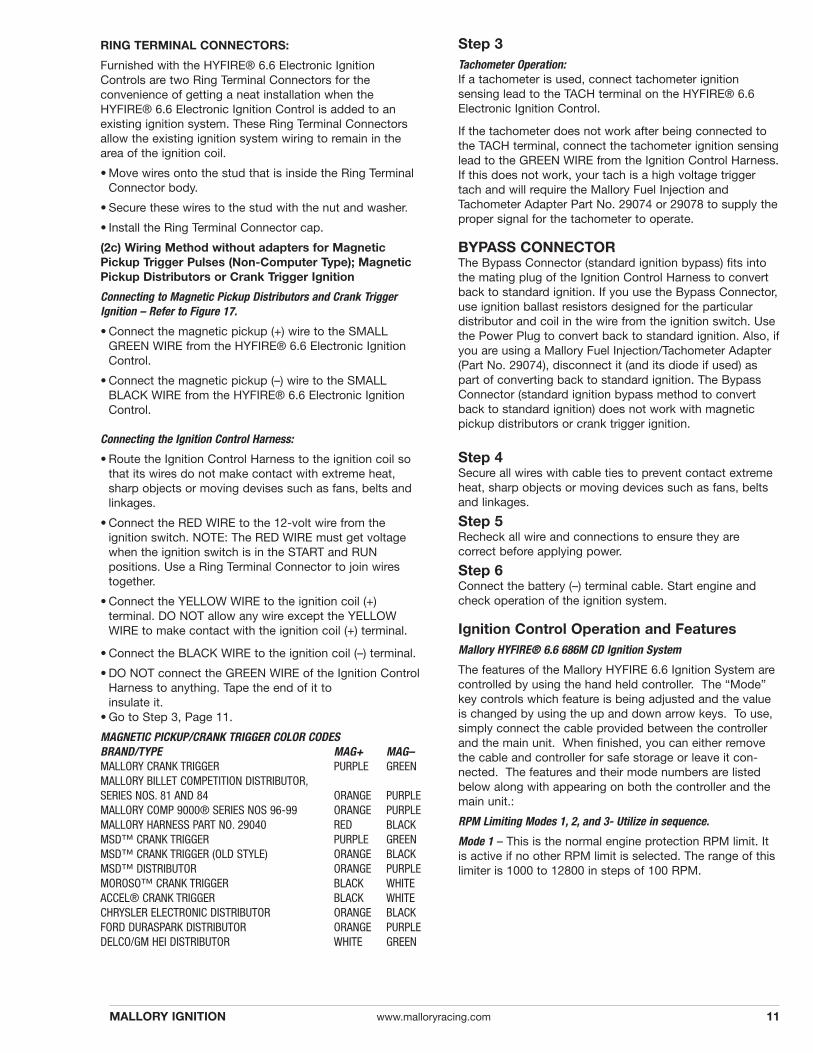
MAGNETIC PICKUP/CRANK TRIGGER COLOR CODESBRAND/TYPE MAG+ MAG–MALLORY CRANK TRIGGER PURPLE GREENMALLORY BILLET COMPETITION DISTRIBUTOR,SERIES NOS. 81 AND 84 ORANGE PURPLEMALLORY COMP 9000® SERIES NOS 96-99 ORANGE PURPLEMALLORY HARNESS PART NO. 29040 RED BLACKMSD™ CRANK TRIGGER PURPLE GREENMSD™ CRANK TRIGGER (OLD STYLE) ORANGE BLACKMSD™ DISTRIBUTOR ORANGE PURPLEMOROSO™ CRANK TRIGGER BLACK WHITEACCEL® CRANK TRIGGER BLACK WHITECHRYSLER ELECTRONIC DISTRIBUTOR ORANGE BLACKFORD DURASPARK DISTRIBUTOR ORANGE PURPLEDELCO/GM HEI DISTRIBUTOR WHITE GREEN
Step 3Tachometer Operation:If a tachometer is used, connect tachometer ignition sensing lead to the TACH terminal on the HYFIRE® 6.6Electronic Ignition Control.
If the tachometer does not work after being connected tothe TACH terminal, connect the tachometer ignition sensinglead to the GREEN WIRE from the Ignition Control Harness.If this does not work, your tach is a high voltage triggertach and will require the Mallory Fuel Injection andTachometer Adapter Part No. 29074 or 29078 to supply theproper signal for the tachometer to operate.
BYPASS CONNECTORThe Bypass Connector (standard ignition bypass) fits intothe mating plug of the Ignition Control Harness to convertback to standard ignition. If you use the Bypass Connector,use ignition ballast resistors designed for the particular distributor and coil in the wire from the ignition switch. Usethe Power Plug to convert back to standard ignition. Also, ifyou are using a Mallory Fuel Injection/Tachometer Adapter(Part No. 29074), disconnect it (and its diode if used) aspart of converting back to standard ignition. The BypassConnector (standard ignition bypass method to convertback to standard ignition) does not work with magneticpickup distributors or crank trigger ignition.
Step 4Secure all wires with cable ties to prevent contact extremeheat, sharp objects or moving devices such as fans, beltsand linkages.
Step 5Recheck all wire and connections to ensure they are correct before applying power.
Step 6Connect the battery (–) terminal cable. Start engine andcheck operation of the ignition system.
Ignition Control Operation and FeaturesMallory HYFIRE® 6.6 686M CD Ignition System
The features of the Mallory HYFIRE 6.6 Ignition System arecontrolled by using the hand held controller. The “Mode”key controls which feature is being adjusted and the valueis changed by using the up and down arrow keys. To use,simply connect the cable provided between the controllerand the main unit. When finished, you can either removethe cable and controller for safe storage or leave it con-nected. The features and their mode numbers are listedbelow along with appearing on both the controller and themain unit.:
RPM Limiting Modes 1, 2, and 3- Utilize in sequence.
Mode 1 – This is the normal engine protection RPM limit. Itis active if no other RPM limit is selected. The range of thislimiter is 1000 to 12800 in steps of 100 RPM.
11MALLORY IGNITION www.malloryracing.com
12 www.malloryracing.com
MALLORY IS A DIVISION OF THE MR. GASKET PERFORMANCE GROUP10601 MEMPHIS AVE. #12, CLEVELAND, OH 44144216.688.8300 FAX 216.688.8306
FORM 1486M06/04
Made in U.S.A.Printed in U.S.A.
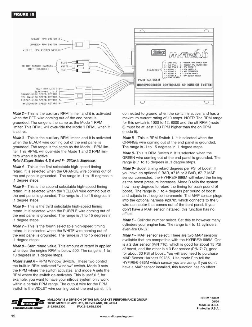
connected to ground when the switch is active, and has amaximum current rating of 10 amps. NOTE: The RPM rangefor this switch is 1000 to 12, 8000 and the off RPM (mode6) must be at least 100 RPM higher than the on RPM(mode 5).
Mode B – This is RPM Switch 1. It is selected when theORANGE wire coming out of the end panel is grounded.The range is .1 to 15 degrees in .1 degree steps.
Mode C– This is RPM Switch 2. It is selected when theGREEN wire coming out of the end panel is grounded. Therange is .1 to 15 degrees in .1 degree steps.
Mode D– Boost timing retard degrees per PSI of boost. Ifyou have an optional 2 BAR, #716 or 3 BAR, #717 MAPsensor connected, the HYFIRE® 686M will retard the timingas the boost pressure increases. Mode D tells the systemhow many degrees to retard the timing for each pound ofboost. The range is .1 to 4 degrees per pound of boostand adjusts in .1 degree increments The MAP sensor plugsinto the optional harness #29785 which connects to the 3wire connector that comes out of the front panel. If youdon’t have a MAP sensor installed, this function has noeffect.
Mode E – Cylinder number select. Set this to however manycylinders your engine has. The range is 4 to 12 cylinders,even-fire ONLY!
Mode F – MAP sensor select. There are two MAP sensorsavailable that are compatible with the HYFIRE® 686M. Oneis a 2 Bar sensor (P/N 716), which is good for about 15 PSIof boost, and the other is a 3 Bar sensor (P/N 717), goodfor about 30 PSI of boost. You will also need to purchaseMAP Sensor Harness 29785. Use mode F to tell theHYFIRE® 686M which sensor you are using. If you don’thave a MAP sensor installed, this function has no effect.
Mode 2 – This is the auxiliary RPM limiter, and it is activatedwhen the RED wire coming out of the end panel is grounded. The range is the same as the Mode 1 RPM limiter. This RPML will over-ride the Mode 1 RPML when itis active.
Mode 3 – This is the auxiliary RPM limiter, and it is activatedwhen the BLACK wire coming out of the end panel isgrounded. The range is the same as the Mode 1 RPM lim-iter. This RPML will over-ride the Mode 1 and 2 RPM lim-iters when it is active.Retard Stages Modes 4, 5, 6 and 7- Utilize in Sequence.
Mode 4 – This is the first selectable high-speed timingretard. It is selected when the ORANGE wire coming out ofthe end panel is grounded. The range is .1 to 15 degrees in.1 degree steps.
Mode 5 – This is the second selectable high-speed timingretard. It is selected when the YELLOW wire coming out ofthe end panel is grounded. The range is .1 to 15 degrees in.1 degree steps.
Mode 6 – This is the third selectable high-speed timingretard. It is selected when the PURPLE wire coming out ofthe end panel is grounded. The range is .1 to 15 degrees in.1 degree steps.
Mode 7 – This is the fourth selectable high-speed timingretard. It is selected when the WHITE wire coming out ofthe end panel is grounded. The range is .1 to 15 degrees in.1 degree steps.
Mode 8 – Start retard value. This amount of retard is appliedwhenever the engine RPM is below 500. The range is .1 to10 degrees in .1 degree steps.
Modes 9 and A – RPM Window Switch. These two controlthe built-in RPM activated “window” switch. Mode 9 setsthe RPM where the switch activates, and mode A sets theRPM where the switch de-activates. This is useful if, forexample, you want to have your nitrous system only workwithin a certain RPM range. The output wire for the RPMswitch is the VIOLET wire coming out of the end panel. It is
FIGURE 18