Embed Size (px)
Citation preview
15. Internationales Holzbau-Forum 09
Footbridges Oloron-Sainte-Marie | J.-F. Blassel/A. Schnubel
1
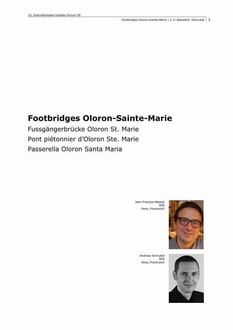
Footbridges Oloron-Sainte-Marie
Fussgängerbrücke Oloron St. Marie
Pont piétonnier d’Oloron Ste. Marie
Passerella Oloron Santa Maria
Jean-François Blassel
RFR
Paris, Frankreich
Andreas Schnubel
RFR
Paris, Frankreich

15. Internationales Holzbau-Forum 09
Footbridges Oloron-Sainte-Marie | J.-F. Blassel/A. Schnubel
2
15. Internationales Holzbau-Forum 09
Footbridges Oloron-Sainte-Marie | J.-F. Blassel/A. Schnubel
3
Footbridges Oloron-Sainte-Marie
The project for the twin footbridges in Oloron Sainte Marie is simple but exemplifies an
integrated design process where all scales, from landscape integration to structural con-
cept and constructive detailing, respond seamlessly to each other.
1. Principles
1.1. Urban context
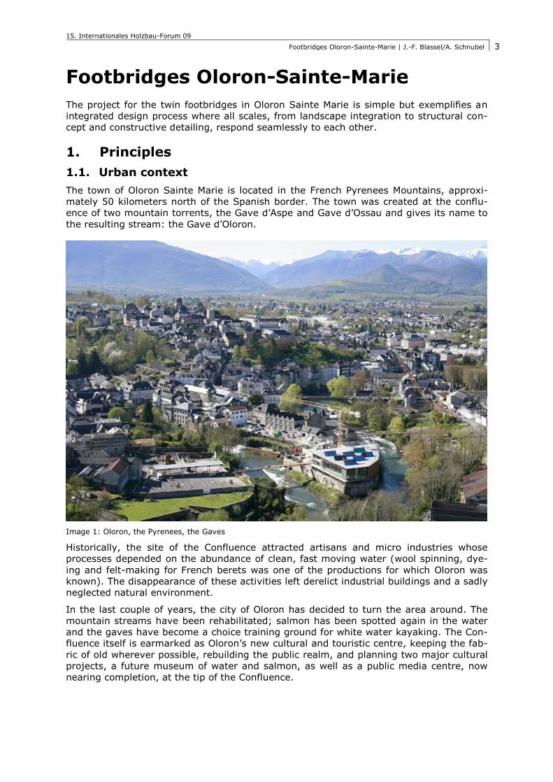
The town of Oloron Sainte Marie is located in the French Pyrenees Mountains, approxi-
mately 50 kilometers north of the Spanish border. The town was created at the conflu-
ence of two mountain torrents, the Gave d’Aspe and Gave d’Ossau and gives its name to
the resulting stream: the Gave d’Oloron.
Image 1: Oloron, the Pyrenees, the Gaves
Historically, the site of the Confluence attracted artisans and micro industries whose
processes depended on the abundance of clean, fast moving water (wool spinning, dye-
ing and felt-making for French berets was one of the productions for which Oloron was
known). The disappearance of these activities left derelict industrial buildings and a sadly
neglected natural environment.
In the last couple of years, the city of Oloron has decided to turn the area around. The
mountain streams have been rehabilitated; salmon has been spotted again in the water
and the gaves have become a choice training ground for white water kayaking. The Con-
fluence itself is earmarked as Oloron’s new cultural and touristic centre, keeping the fab-
ric of old wherever possible, rebuilding the public realm, and planning two major cultural
projects, a future museum of water and salmon, as well as a public media centre, now
nearing completion, at the tip of the Confluence.
15. Internationales Holzbau-Forum 09
Footbridges Oloron-Sainte-Marie | J.-F. Blassel/A. Schnubel
4
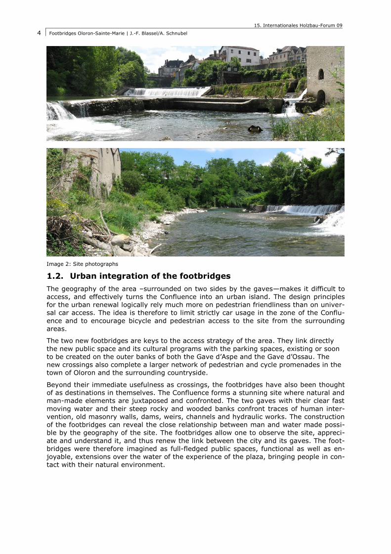
Image 2: Site photographs
1.2. Urban integration of the footbridges
The geography of the area –surrounded on two sides by the gaves—makes it difficult to
access, and effectively turns the Confluence into an urban island. The design principles
for the urban renewal logically rely much more on pedestrian friendliness than on univer-
sal car access. The idea is therefore to limit strictly car usage in the zone of the Conflu-
ence and to encourage bicycle and pedestrian access to the site from the surrounding
areas.
The two new footbridges are keys to the access strategy of the area. They link directly
the new public space and its cultural programs with the parking spaces, existing or soon
to be created on the outer banks of both the Gave d’Aspe and the Gave d’Ossau. The
new crossings also complete a larger network of pedestrian and cycle promenades in the
town of Oloron and the surrounding countryside.
Beyond their immediate usefulness as crossings, the footbridges have also been thought
of as destinations in themselves. The Confluence forms a stunning site where natural and
man-made elements are juxtaposed and confronted. The two gaves with their clear fast
moving water and their steep rocky and wooded banks confront traces of human inter-
vention, old masonry walls, dams, weirs, channels and hydraulic works. The construction
of the footbridges can reveal the close relationship between man and water made possi-
ble by the geography of the site. The footbridges allow one to observe the site, appreci-
ate and understand it, and thus renew the link between the city and its gaves. The foot-
bridges were therefore imagined as full-fledged public spaces, functional as well as en-
joyable, extensions over the water of the experience of the plaza, bringing people in con-
tact with their natural environment.
15. Internationales Holzbau-Forum 09
Footbridges Oloron-Sainte-Marie | J.-F. Blassel/A. Schnubel
5
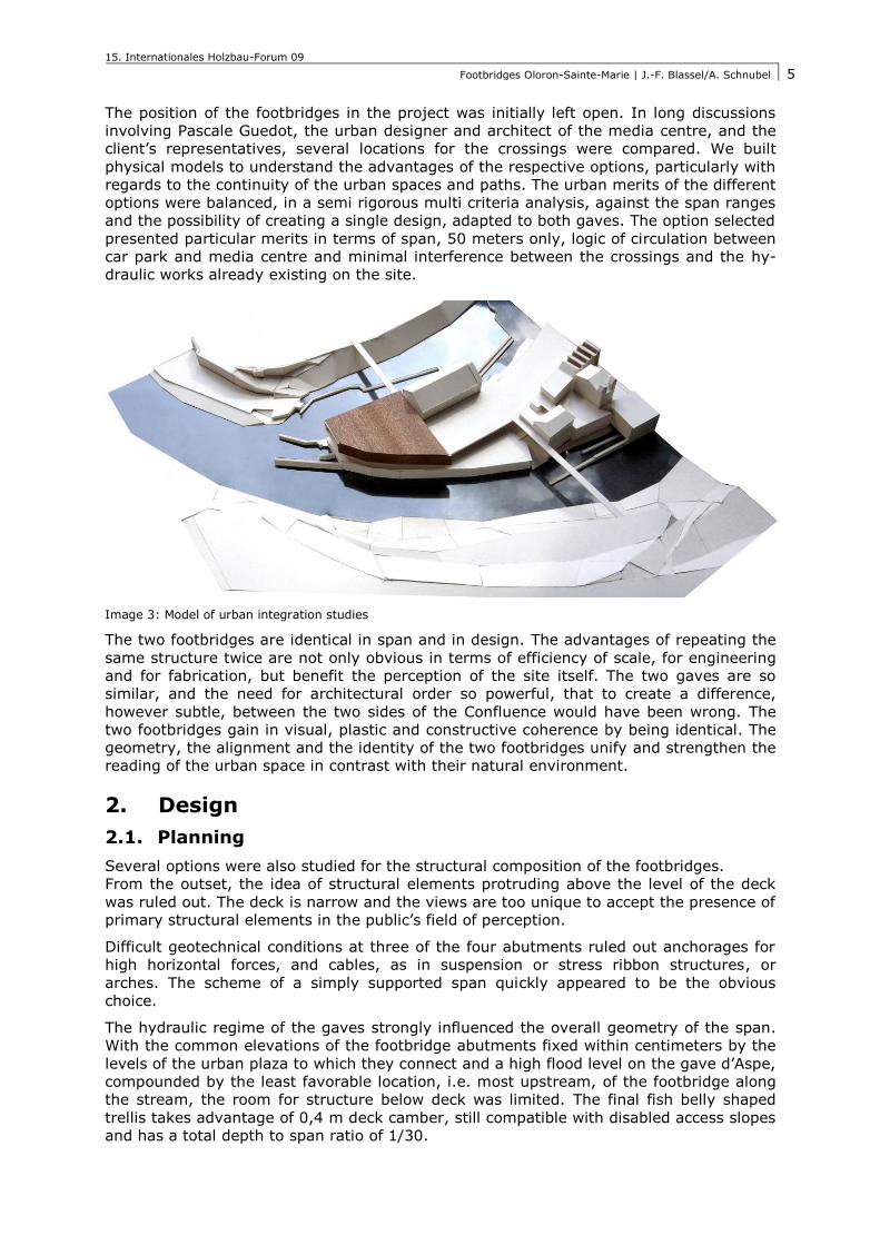
The position of the footbridges in the project was initially left open. In long discussions
involving Pascale Guedot, the urban designer and architect of the media centre, and the
client’s representatives, several locations for the crossings were compared. We built
physical models to understand the advantages of the respective options, particularly with
regards to the continuity of the urban spaces and paths. The urban merits of the different
options were balanced, in a semi rigorous multi criteria analysis, against the span ranges
and the possibility of creating a single design, adapted to both gaves. The option selected
presented particular merits in terms of span, 50 meters only, logic of circulation between
car park and media centre and minimal interference between the crossings and the hy-
draulic works already existing on the site.
Image 3: Model of urban integration studies
The two footbridges are identical in span and in design. The advantages of repeating the
same structure twice are not only obvious in terms of efficiency of scale, for engineering
and for fabrication, but benefit the perception of the site itself. The two gaves are so
similar, and the need for architectural order so powerful, that to create a difference,
however subtle, between the two sides of the Confluence would have been wrong. The
two footbridges gain in visual, plastic and constructive coherence by being identical. The
geometry, the alignment and the identity of the two footbridges unify and strengthen the
reading of the urban space in contrast with their natural environment.
2. Design
2.1. Planning
Several options were also studied for the structural composition of the footbridges.
From the outset, the idea of structural elements protruding above the level of the deck
was ruled out. The deck is narrow and the views are too unique to accept the presence of
primary structural elements in the public’s field of perception.
Difficult geotechnical conditions at three of the four abutments ruled out anchorages for
high horizontal forces, and cables, as in suspension or stress ribbon structures, or
arches. The scheme of a simply supported span quickly appeared to be the obvious
choice.
The hydraulic regime of the gaves strongly influenced the overall geometry of the span.
With the common elevations of the footbridge abutments fixed within centimeters by the
levels of the urban plaza to which they connect and a high flood level on the gave d’Aspe,
compounded by the least favorable location, i.e. most upstream, of the footbridge along
the stream, the room for structure below deck was limited. The final fish belly shaped
trellis takes advantage of 0,4 m deck camber, still compatible with disabled access slopes
and has a total depth to span ratio of 1/30.
15. Internationales Holzbau-Forum 09
Footbridges Oloron-Sainte-Marie | J.-F. Blassel/A. Schnubel
6
With such an unusually low ratio, the advantages of using as much as possible of the
constructive depth for structural use led to the replacement of the conventional timber
decking stacked over a hierarchical support structure by a more substantial and compact
solution. In this case, the upper chord of the structure becomes the walking surface of
the footbridge. The upper chord of the span becomes as wide as the footbridge itself and
the resulting massive section of the deck beam is well adapted to the significant axial
forces generated the shallow structural depth.
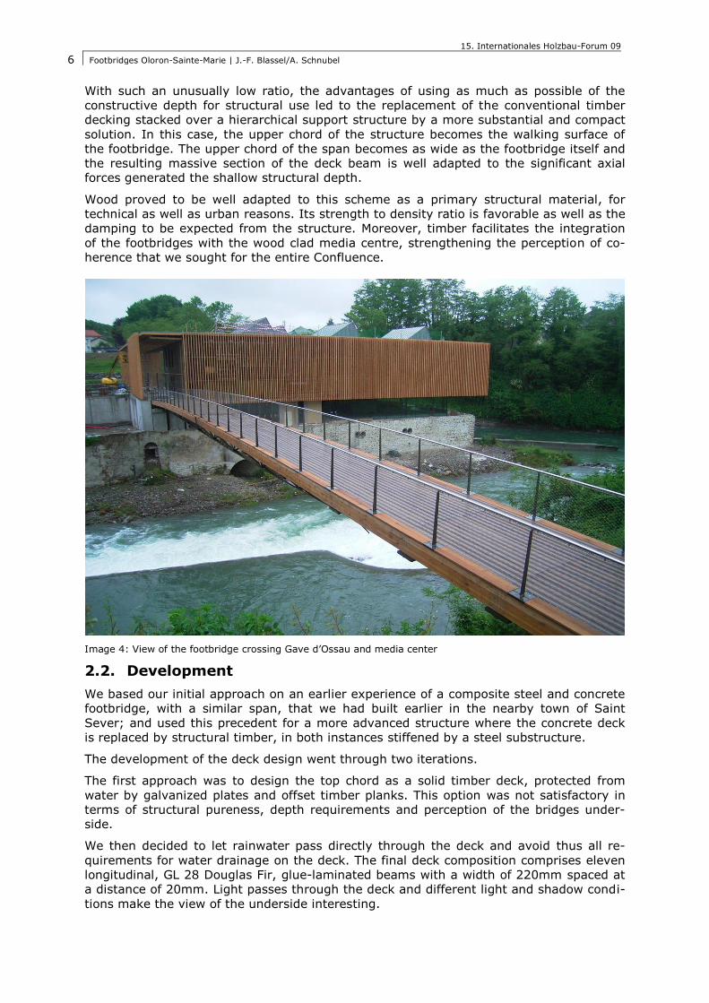
Wood proved to be well adapted to this scheme as a primary structural material, for
technical as well as urban reasons. Its strength to density ratio is favorable as well as the
damping to be expected from the structure. Moreover, timber facilitates the integration
of the footbridges with the wood clad media centre, strengthening the perception of co-
herence that we sought for the entire Confluence.
Image 4: View of the footbridge crossing Gave d’Ossau and media center
2.2. Development
We based our initial approach on an earlier experience of a composite steel and concrete
footbridge, with a similar span, that we had built earlier in the nearby town of Saint
Sever; and used this precedent for a more advanced structure where the concrete deck
is replaced by structural timber, in both instances stiffened by a steel substructure.
The development of the deck design went through two iterations.
The first approach was to design the top chord as a solid timber deck, protected from
water by galvanized plates and offset timber planks. This option was not satisfactory in
terms of structural pureness, depth requirements and perception of the bridges under-
side.
We then decided to let rainwater pass directly through the deck and avoid thus all re-
quirements for water drainage on the deck. The final deck composition comprises eleven
longitudinal, GL 28 Douglas Fir, glue-laminated beams with a width of 220mm spaced at
a distance of 20mm. Light passes through the deck and different light and shadow condi-
tions make the view of the underside interesting.
15. Internationales Holzbau-Forum 09
Footbridges Oloron-Sainte-Marie | J.-F. Blassel/A. Schnubel
7
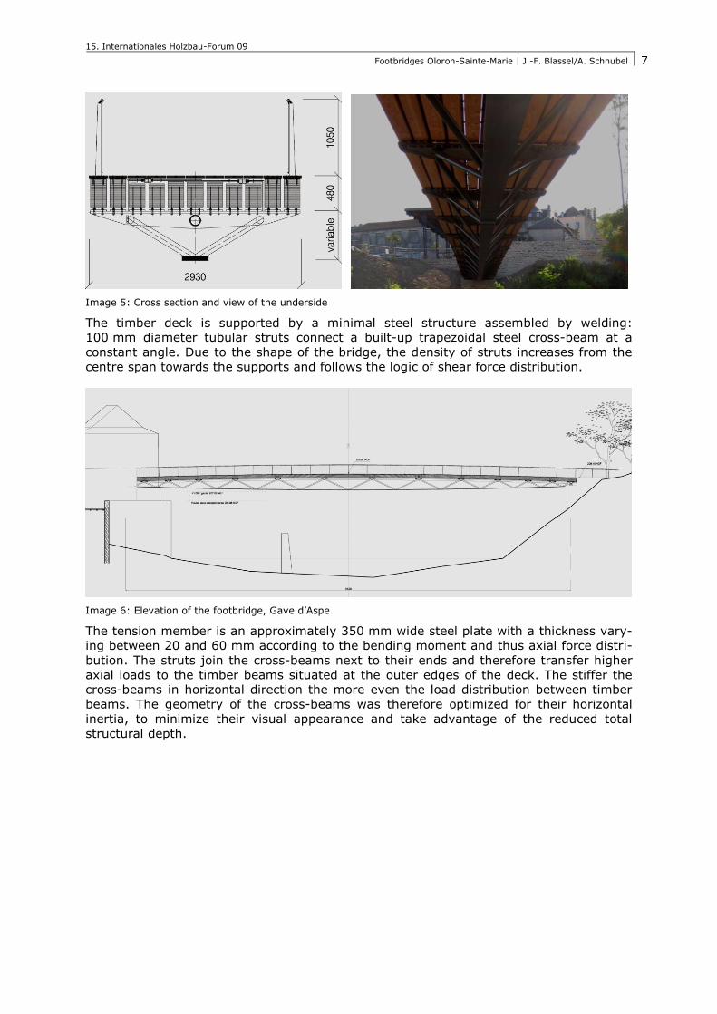
Image 5: Cross section and view of the underside
The timber deck is supported by a minimal steel structure assembled by welding:
100 mm diameter tubular struts connect a built-up trapezoidal steel cross-beam at a
constant angle. Due to the shape of the bridge, the density of struts increases from the
centre span towards the supports and follows the logic of shear force distribution.
Image 6: Elevation of the footbridge, Gave d’Aspe
The tension member is an approximately 350 mm wide steel plate with a thickness vary-
ing between 20 and 60 mm according to the bending moment and thus axial force distri-
bution. The struts join the cross-beams next to their ends and therefore transfer higher
axial loads to the timber beams situated at the outer edges of the deck. The stiffer the
cross-beams in horizontal direction the more even the load distribution between timber
beams. The geometry of the cross-beams was therefore optimized for their horizontal
inertia, to minimize their visual appearance and take advantage of the reduced total
structural depth.
15. Internationales Holzbau-Forum 09
Footbridges Oloron-Sainte-Marie | J.-F. Blassel/A. Schnubel
8
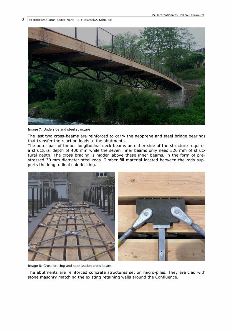
Image 7: Underside and steel structure
The last two cross-beams are reinforced to carry the neoprene and steel bridge bearings
that transfer the reaction loads to the abutments.
The outer pair of timber longitudinal deck beams on either side of the structure requires
a structural depth of 400 mm while the seven inner beams only need 320 mm of struc-
tural depth. The cross bracing is hidden above these inner beams, in the form of pre-
stressed 30 mm diameter steel rods. Timber fill material located between the rods sup-
ports the longitudinal oak decking.
Image 8: Cross bracing and stabilization cross-beam
The abutments are reinforced concrete structures set on micro-piles. They are clad with
stone masonry matching the existing retaining walls around the Confluence.
15. Internationales Holzbau-Forum 09
Footbridges Oloron-Sainte-Marie | J.-F. Blassel/A. Schnubel
9
2.3. Decking and Equipment
The structural timber used for the footbridges is Douglas fir, a species that is naturally
resistant to biological attacks (class 3, as per EN 355). The deck beams are further pro-
tected by the decking, made of 30mm oak planks placed in the longitudinal direction, one wide reconstituted board per deck beam. A Rephanol™ waterproofing foil, sandwiched
between the longitudinal beams and the decking, provides further protection against
moisture. The oak decking forms the wear surface for pedestrians and cyclists. It can be
easily replaced in time, along with the waterproof membrane. Each decking plank re-
ceived two of anti-sliding strips, made of an epoxy resin and sand filled groove. The deck
construction is completed by a balustrade composed of a simple stainless net stretched
on trapezoidal posts connected by a polished stainless steel handrail.
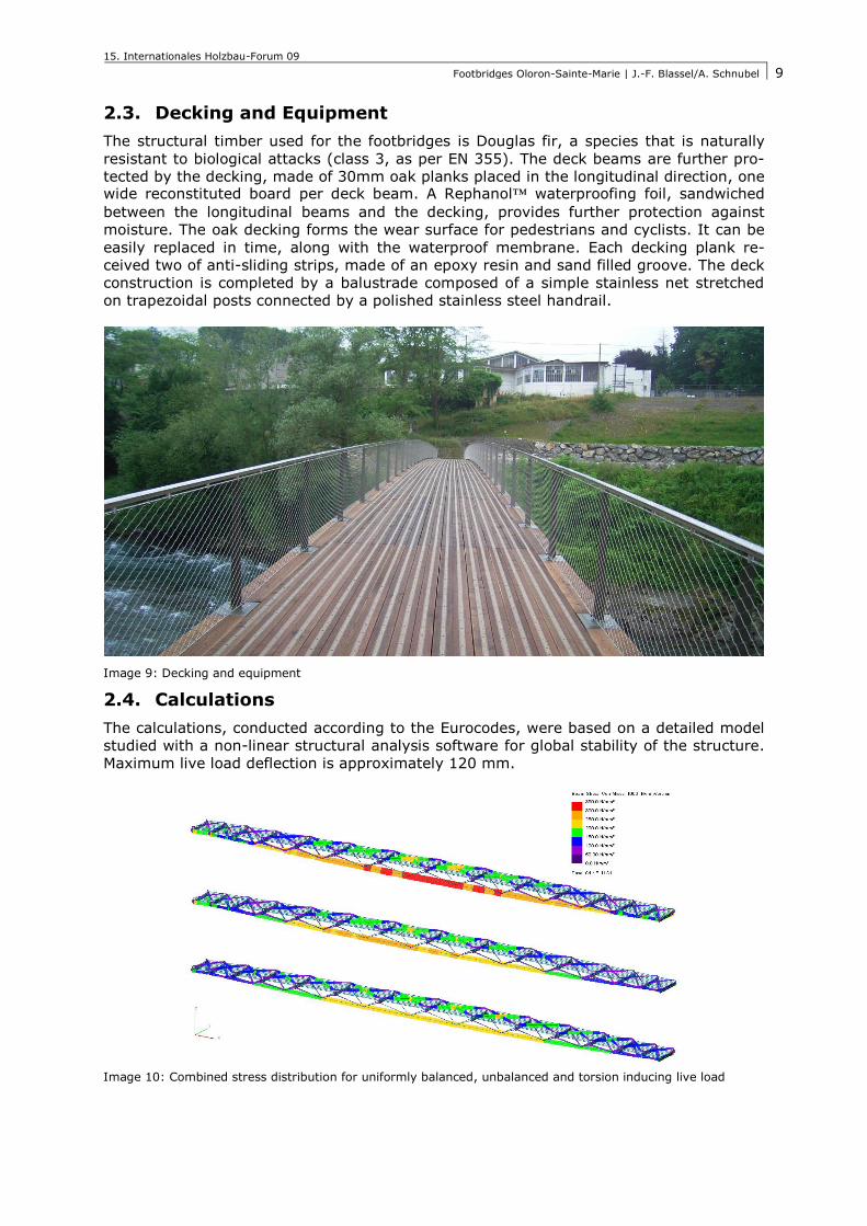
Image 9: Decking and equipment
2.4. Calculations
The calculations, conducted according to the Eurocodes, were based on a detailed model
studied with a non-linear structural analysis software for global stability of the structure.
Maximum live load deflection is approximately 120 mm.
Image 10: Combined stress distribution for uniformly balanced, unbalanced and torsion inducing live load
15. Internationales Holzbau-Forum 09
Footbridges Oloron-Sainte-Marie | J.-F. Blassel/A. Schnubel
10
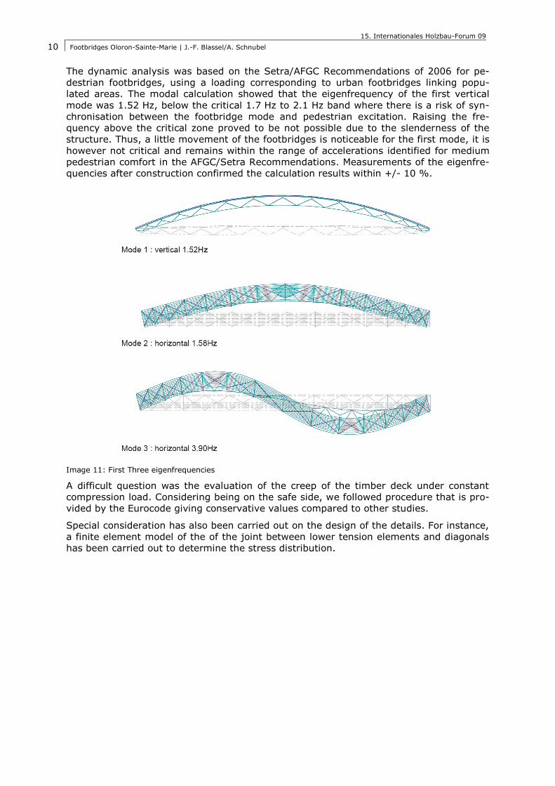
The dynamic analysis was based on the Setra/AFGC Recommendations of 2006 for pe-
destrian footbridges, using a loading corresponding to urban footbridges linking popu-
lated areas. The modal calculation showed that the eigenfrequency of the first vertical
mode was 1.52 Hz, below the critical 1.7 Hz to 2.1 Hz band where there is a risk of syn-
chronisation between the footbridge mode and pedestrian excitation. Raising the fre-
quency above the critical zone proved to be not possible due to the slenderness of the
structure. Thus, a little movement of the footbridges is noticeable for the first mode, it is
however not critical and remains within the range of accelerations identified for medium
pedestrian comfort in the AFGC/Setra Recommendations. Measurements of the eigenfre-
quencies after construction confirmed the calculation results within +/- 10 %.
Image 11: First Three eigenfrequencies
A difficult question was the evaluation of the creep of the timber deck under constant
compression load. Considering being on the safe side, we followed procedure that is pro-
vided by the Eurocode giving conservative values compared to other studies.
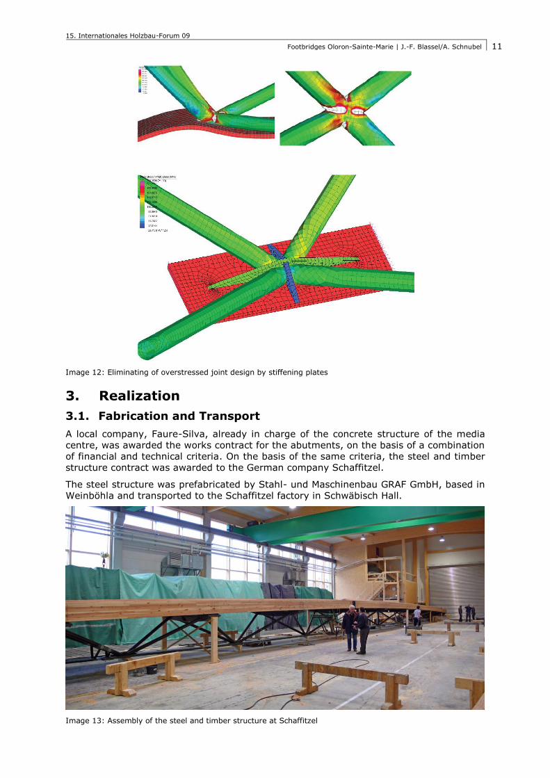
Special consideration has also been carried out on the design of the details. For instance,
a finite element model of the of the joint between lower tension elements and diagonals
has been carried out to determine the stress distribution.
15. Internationales Holzbau-Forum 09
Footbridges Oloron-Sainte-Marie | J.-F. Blassel/A. Schnubel
11
Image 12: Eliminating of overstressed joint design by stiffening plates
3. Realization
3.1. Fabrication and Transport
A local company, Faure-Silva, already in charge of the concrete structure of the media
centre, was awarded the works contract for the abutments, on the basis of a combination
of financial and technical criteria. On the basis of the same criteria, the steel and timber
structure contract was awarded to the German company Schaffitzel.
The steel structure was prefabricated by Stahl- und Maschinenbau GRAF GmbH, based in
Weinböhla and transported to the Schaffitzel factory in Schwäbisch Hall.
Image 13: Assembly of the steel and timber structure at Schaffitzel
15. Internationales Holzbau-Forum 09
Footbridges Oloron-Sainte-Marie | J.-F. Blassel/A. Schnubel
12
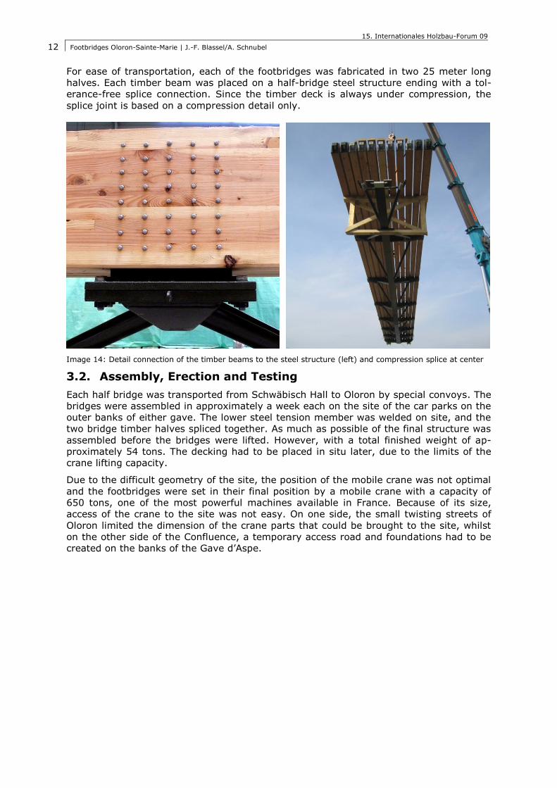
For ease of transportation, each of the footbridges was fabricated in two 25 meter long
halves. Each timber beam was placed on a half-bridge steel structure ending with a tol-
erance-free splice connection. Since the timber deck is always under compression, the
splice joint is based on a compression detail only.
Image 14: Detail connection of the timber beams to the steel structure (left) and compression splice at center
3.2. Assembly, Erection and Testing
Each half bridge was transported from Schwäbisch Hall to Oloron by special convoys. The
bridges were assembled in approximately a week each on the site of the car parks on the
outer banks of either gave. The lower steel tension member was welded on site, and the
two bridge timber halves spliced together. As much as possible of the final structure was
assembled before the bridges were lifted. However, with a total finished weight of ap-
proximately 54 tons. The decking had to be placed in situ later, due to the limits of the
crane lifting capacity.
Due to the difficult geometry of the site, the position of the mobile crane was not optimal
and the footbridges were set in their final position by a mobile crane with a capacity of
650 tons, one of the most powerful machines available in France. Because of its size,
access of the crane to the site was not easy. On one side, the small twisting streets of
Oloron limited the dimension of the crane parts that could be brought to the site, whilst
on the other side of the Confluence, a temporary access road and foundations had to be
created on the banks of the Gave d’Aspe.
15. Internationales Holzbau-Forum 09
Footbridges Oloron-Sainte-Marie | J.-F. Blassel/A. Schnubel
13
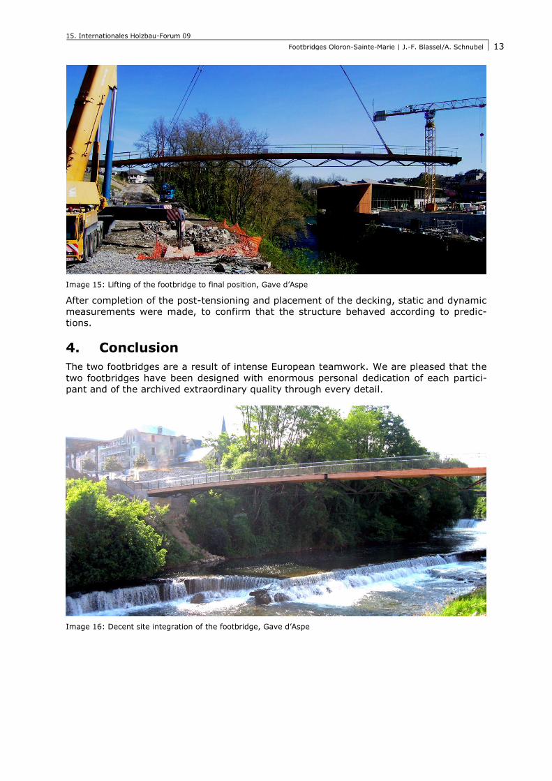
Image 15: Lifting of the footbridge to final position, Gave d’Aspe
After completion of the post-tensioning and placement of the decking, static and dynamic
measurements were made, to confirm that the structure behaved according to predic-
tions.
4. Conclusion
The two footbridges are a result of intense European teamwork. We are pleased that the
two footbridges have been designed with enormous personal dedication of each partici-
pant and of the archived extraordinary quality through every detail.
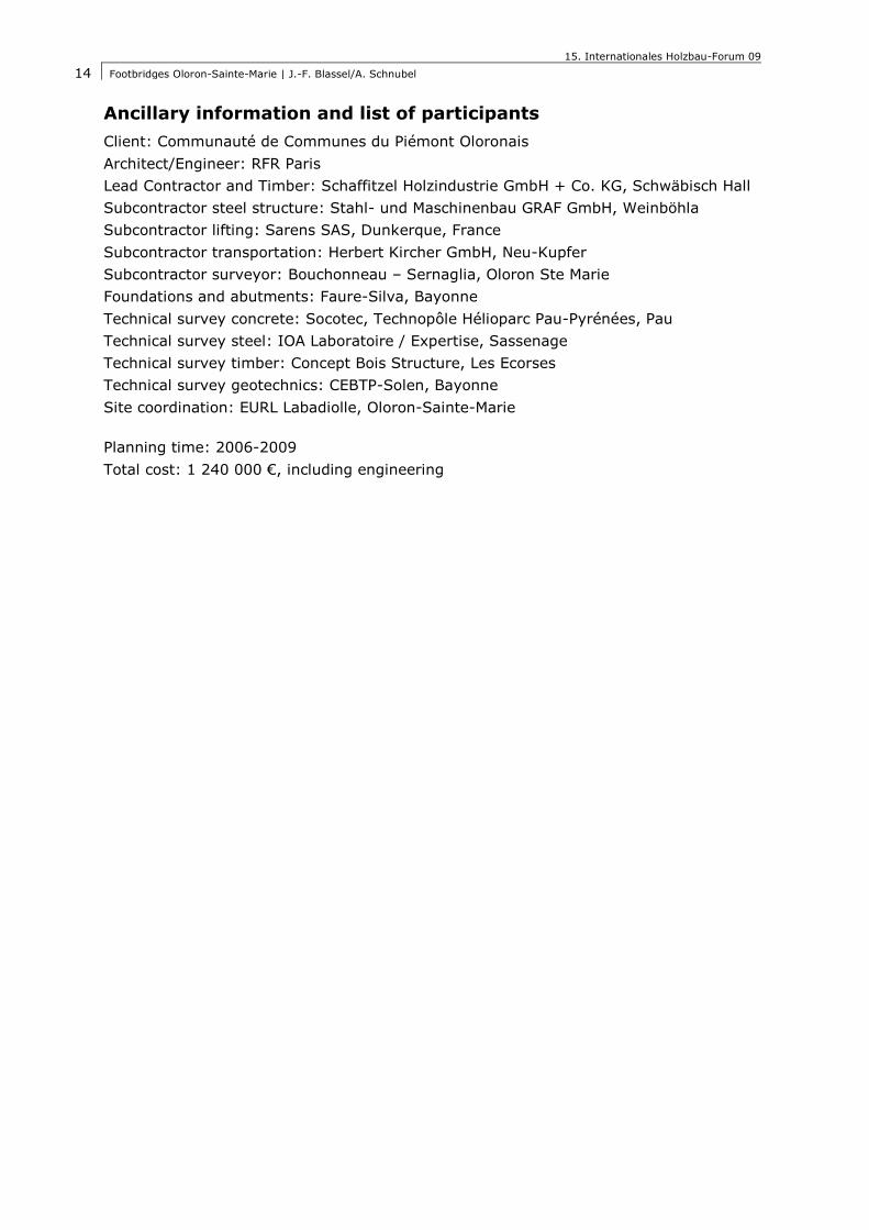
Image 16: Decent site integration of the footbridge, Gave d’Aspe
15. Internationales Holzbau-Forum 09
Footbridges Oloron-Sainte-Marie | J.-F. Blassel/A. Schnubel
14
Ancillary information and list of participants
Client: Communauté de Communes du Piémont Oloronais
Architect/Engineer: RFR Paris
Lead Contractor and Timber: Schaffitzel Holzindustrie GmbH + Co. KG, Schwäbisch Hall
Subcontractor steel structure: Stahl- und Maschinenbau GRAF GmbH, Weinböhla
Subcontractor lifting: Sarens SAS, Dunkerque, France
Subcontractor transportation: Herbert Kircher GmbH, Neu-Kupfer
Subcontractor surveyor: Bouchonneau – Sernaglia, Oloron Ste Marie
Foundations and abutments: Faure-Silva, Bayonne
Technical survey concrete: Socotec, Technopôle Hélioparc Pau-Pyrénées, Pau
Technical survey steel: IOA Laboratoire / Expertise, Sassenage
Technical survey timber: Concept Bois Structure, Les Ecorses
Technical survey geotechnics: CEBTP-Solen, Bayonne
Site coordination: EURL Labadiolle, Oloron-Sainte-Marie
Planning time: 2006-2009
Total cost: 1 240 000 €, including engineering