Embed Size (px)
Citation preview

•̂
Roll-Around Finishing Cabinet • Note BoarAccent Carving • Sanding Tips • Circle Sanding Jig
\\foodsmithVol. 16/No. 96
CountryHutch

No. 96 December, 1994
EditorExecutive EditorManaging Editor
Assistant Editors
Creative DirectorArt Director
Senior Illustrators
Illustrators
PhotographerElectronic Graphics
Design DirectorSenior Designer
Shop ManagerShop Asst./Facilities
Circulation DirectorSubscription Manager
Direct Mail ManagerNewsstand Sales
Donald B. PeschkeDouglas L. HicksTerry J. StrohmanJames M. DolanJonathan GarbisonMark A. Williams
Ted KralicekRod StoakesDavid KreylingCinda ShambaughDirkVerSteegMark HigdonCrayola EnglandChris GlowackiKen MunkelKent WelshSteve CurtisSteve Johnson
Liz BredesonSandy BaumTroy J. Do wellKent A. Buckton
PUBLISHING SERVICESMgr: Gordon Gaippe • Graph. Artist: Cheryl L Cynor
CORPORATE SERVICES
Planning Director: Jon Macarthy • Controller: RobinHutchinson •Account.: Laura Thomas • Bookkeeping:Julie Greenlee • Production, Mgr.: Carol Quijano • Info.Serv. Mgr.: Joyce Moore • Elec. Pub. Coord.:Douglas M. Lidster • Applic. Spec.: Linda Morrow• Sup. Asst: Nick Thielen • Admin. Assistants:Cheryl A. Scott, Julia Fish •Receptionist JeanneJohnson • Build. Maint: Ken Griffith
WOODSMITH MAIL ORDERArt Dir.: Cindy Jackson •Catalog Prod. Mgr.: BobBaker • Inv. Control/Prod. Mgr.: Mark Mattiussi• Proj. Supplies: Linda Jones • Tech. Supp: Jeff Janes
CUSTOMER SERVICESupervisor: Jennie Enos • Customer Service Reps.:Jennifer Murphy, Joy Krause, Sara Kono, AnnaCox, Lonnie Algreen, Karla Cronin
SHIPPING DEPARTMENTSupr: Nancy Johnson • Fulfillment Gloria Sheehan,Chuck Carlson, Sylvia Carey, Larry Prine
WOODSMITH STOREManager: Dave Larson •Assistant Manager: PaulSchneider •Sales Staff: Wendell Stone, Pat Lowery• Office Manager: Vicki Edwards
Woodsmith® (ISSN 0164-4114) is published bimonthly(Feb., Apr., June, Aug., Oct., Dec.) by Woodsmith Corp.,2200 Grand, Des Moines, IA 50312.Woodsmith® is a registered trademark of Woodsmith Corp.Copyright© 1994 Woodsmith Corporation. All rights reserved.Subscriptions: Single copy: $3.95. One year subscription (6issues), $19.95. Two years (12 issues), $35.95. (Canada/For-eign add $5 per year, U.S. funds.)Second Class Postage Paid at Des Moines, IA and at addi-tional offices.Postmaster: Send change of address to Woodsmith, Box10718, Des Moines, IA 50350.Subscription Questions? Call 1-800-333-5075, 8:00 amto 5:00 pm, Central Time, weekdays.E-Mail. Prodigy: EDJE97A, CompuServe: 75330,2301, [email protected]., America Online: Donpeschke.
E D I T O R ' S C O L U M N
SawdustIt's the smell that does it Every time I
start to work on a pine project it takesme back to the days when I first startedwoodworking.
To tell the truth, that was so many yearsago I don't remember most of the projectsI built. But Fll never forget the aroma thatfilled the air when I made my first cut intoa piece of pine.
Like many beginning woodworkers Iused pine because it was readily available.You could buy it at any lumberyard. And itwas inexpensive. Something that was veryimportant when you made as many mis-takes as I did.
I still make mistakes (fortunately, notquite as many as I used to). But I never lostmy affection for building pine projects.
Pine is still relatively inexpensive andreadily available. But it's also versatile. Inthis issue all three projects, The CountryHutch on page 6, the Note Board on page18, and the Finishing Cabinet on page 24,are built using pine lumber.
NEW LOOK. There's another thing I'vegotten a little nostalgic about — the cover.I've always felt the cover of a magazineshould reflect what's inside.
And while we've made several changesto the inside of Woodsmith over the years,
the cover has remained basically the same.I knew that I wanted to make somechanges but I kept putting it off.
It's sort of like staring at the same face inthe mirror. You'd like to improve the way itlooks. But you're a little worried that if youdo, your friends won't recognize you.
Well we finally decided to quit putting itoff and go ahead and make some changes.The biggest change we made was to theWoodsmith name on the cover.
We've also included a list of some of theprojects and articles in the issue across thetop of the cover. This allows you to tell at aglance what's inside.
NEW FACE. The cover of this issue isn'tthe only thing that's new around here.We've added another member to theWoodsmith family. Troy Dowell has joinedus as direct mail manager. Troy will beworking in our circulation department andwill try to make sense out of all the namesand numbers.
PUBLISHER'S STATEMENT. Speaking of
numbers, once a year the post office re-quires that we print a Publisher's State-ment, see below. It has a lot of numbers init, but the good news is we continue togrow. For being part of this growth and foryour continued support, I thank you.
STATEMENT OF OWNERSHIP, MANAGEMENT AND CIRCULATION(Required by 39 U.S.C. 3685)
1. Title of Publication: Woodsmith. la. Publication No.: 01644114. 2. Date of Filing: September 1,1994. 3. Frequency of issue:Bimonthly. 3a. No. of issues published annually: 6 (six). 3b. Annual subscription price: $ 19.95. 4. Complete mailing address ofknown office of publication. 2200 Grand Avenue, Des Moines, (Polk County), Iowa 50312-5306. 5. Complete mailing addressof the headquarters of general business offices of the publisher: 2200 Grand Avenue, Des Moines, Iowa 50312-5306. 6. Fullnames and complete mailing address of publisher, editor, and managing editor: Publisher and Editor: Donald B. Peschke,2200 Grand Avenue, Des Moines, Iowa 50312; Managing Editor: Terry J. Strohman, 2200 Grand Avenue, Des Moines, Iowa50312. 7. Owner: Woodsmith Corporation, 2200 Grand Avenue, Des Moines, Iowa 50312; Donald B. Peschke, 2200 GrandAvenue, Des Moines, Iowa 50312. 8. Known bondholders, mortgagees, and other security holders owning 1 percent or moreof total amount of bonds, mortgages or other securities: None. 9. (Does not apply.) 10. Extent and nature of circulation:
Average no. copies each Average no. copies ofissue during preceding single issue published
12 months nearest to filing date
A Total no. copies printed (net press run) 432,508 461,715B. Paid and/or requested circulation:
1. Sales through dealers, street vendors and counter sales 23,777 37,1472. Mail subscriptions (paid and/or requested) 374,954 395,264
C. Total paid and/or requested circulation 398,731 432,411D. Free distribution by mail, carrier or other means, samples,
complimentary, and other free copies Ill 106E. Total distribution 398,842 432,517F. Copies not distributed
1. Office use, left over, unaccounted, spoiled after printing 13,845 22,3592. Returns from news agents 19,821 6,839
G. Total 432,508 461,71511.1 certify that the statements made by me above are correct and complete.
(signed) Donald B. Peschke, Editor
Woodsmith No. 96

A L O O K I N S I D E
ContentsCountry Hutch 6
Simple design and basic joinery make this Hutch easy tobuild. Knotty pine boards give it a country appearance andkeep it affordable, too.
Note Board 18Make this Note Board to fit your favorite calendar. Thenadd an angled shelf to hold a note pad, with a lip on the frontto keep writing tools from rolling off.
Accent Carving 20This carving technique is easy to master by following ourstep-by-step drawings. Also, tips for choosing the best wood,laying out the pattern, and producing clean, crisp details.
Sanding Tips 22A collection of practical sanding tips to help you producemore professional finishes every time, with less work.
Finishing Cabinet 24A roll-around cabinet that makes the job of finishing moreconvenient. The top revolves on a shop-made "lazy susan."
Circle Sanding Jig 30Produce perfectly round—and smooth—circles using thisjig on a disc sander. It's easily adjustable to a range of sizes.
Tips & Techniques 4Shop Notes 16Talking Shop 29Sources 31
Country Hutch
Note Board
page 6
page 18
Finishing Cabinet page 24
No. 96 Woodsmith

F R O M F E L L O W W O O D W O R K E R S
Tips & TechniquesGLUING MITERS• Getting picture frames mi-tered to exactly 90° is hardenough. But then when youglue and clamp the corners to-gether they always slide apart.
But I've found a simple solu-
tion. On the back side of theframe, I'll use one or two staplesto hold each corner together be-fore I glue them, see Fig. 1.
The staples let the cornersopen from the front side so the
glue can get in, see Fig. 2. Andthey keep the corners aligned asthe clamps are tightened, seeFig. 3. After the glue dries, thestaples are easily removed.
Oh, by the way. Instead of us-
ing nails or those triangle-shaped push points to holdeverything in the frame, try hotmelt glue — it works great
George MerrittNepean, Ontario
Openmiter andapply glue
Lightly damp the piecesand remove stapleswhen the glue dries
— Front sideof frameStaples keep
pieces from shiftingStaple back side of frame at corners
ELIMINATING SNIPE• No matter how well I adjustmy thickness planer, wheneverI use it, the planer always cuts adeeper slice (snipe) at bothends of the board.
To eliminate the waste, I add"sacrificial" boards to my work-piece, see drawing. They'reabout 6" longer than my stock,so they get all of the snipe.
I use small dabs of hot meltglue to attach the scrap pieces tothe sides. Then I feed the boardsthrough the planer.
Once the workpiece is planedto size, the scrap pieces are eas-ily removed. And any glue resi-due can be quickly scraped off.
Chuck EnfieldBrooklyn Park, Minnesota
— Snipe on endsor workpiece
Attach sacrificial boardsto workpiece with hot melt glue
SPACING HOLES• When installing shelves, ittakes time to measure and drillthe holes for the shelf supports.And it doesn't take much to getoff just a hair. So I use a simplejig to keep the holes alignedwithout all the measuring.
The jig is a piece of wood withfour holes drilled in it. In two ofthe holes, dowels are installed
as indexing pins, see drawing.To use the jig, first drill two
holes in the board. Then posi-tion the dowels in these holes,and use the jig when drilling thenext two holes. By leap-froggingthe jig down the board all theholes are drilled evenly spaced.
JeffScrogginsOaklahoma City, Oklahoma
FIRST: Drill twoholes on workpiece
Q>
SECOND:Position
dowels in holesbefore drilling
^
Woodsmtth No. 96

BLAST GATE• I recently purchased a dustcollector for my shop. Addingblast gates would make the col-lector easier to use. But it's tooexpensive for me to buy a blastgate for each machine.
So I decided to make my ownblast gates using plywood andmetal duct pipes, see photo.(PVC tubing would also work.)I started with two pieces of 3/4!l-thick plywood and cut out a holethe same size as the outside di-ameter of the pipe, see drawing.
Next, Vfc"-thick Masonitespacers fit between the ply-wood. This creates a gap for asliding gate to fit into. Then glueand screw the plywood andspacers together.
I made the sliding gate fromanother piece of W-thick Ma-sonite. A block glued on topforms a handle, and a screw inthe bottom of the gate keeps itfrom being pulled all the way outwhen the gate is opened.
Then cut and install twopieces of metal duct pipe in theplywood. Install the pipe so it'sflush with the inside edge. Youdon't want the pipe to bind
against the sliding gate. Note:for an airtight seal use caulkaround the outside of the pipe.
Steven MagdemmjcrBel Air, Maryland
3A" plywood -^ Gate —
Female end
s- Glue handleto gate
Male end
#8x1V4"FhWoodscrews
-__^=— Vs" Masonitespacers
DETAIL
Caulkaround
outside ofpipe for an
airtight *r.,, seal
Screwkeeps
gate frompulling
out'
il/ til
ANGLE GAUGE• I do a lot of scroll saw workthat requires changing the an-gle of the table. But the stampedaluminum scale under the tableisn't very accurate, and it's hard
to read. So I made an anglegauge that uses an inexpensiveplastic protractor.
The angle gauge is simply ablock of wood with the protrac-
tor screwed to the side, see Fig.1. A piece of wire suspendedfrom the centerpoint indicatesthe degree of angle, see Fig. 2.
To use the angle gauge, first
Wood blockDrill hole at 90°locationand screw protractor to block
Wire pointsto angle when
table is tilted
adjust the protractor so the wireindicates 90° before changingthe angle of the table.
Jim PenkalaCalistoga, California
SUBMIT YOUR TIPS
If you would like to sharean original shop-tested tip,send it to Woodsmith, Tipsand Techniques, 2200 GrandAvenue, Des Moines, Iowa50312. Or if if s easier for you,FAXit to us at 515-282-6741.
If we publish it, we willsend you $30 to $150, depend-ing on the published length.Include a brief explanationand sketch (or photo). Anddon't worry, we'll rewrite thetip and redraw the art if nec-essary. Also, please include adaytime phone number.
No. 96 Woodsmith

F E A T U R E P R O J E C T
Country HutchKnotty pine boards give this Hutch an authentic "country" look,
Simple design and joinery make it easy to build.
Around here, change is a daily routine. Originally,I planned to build this Hutch from clear pine.
That plan changed at the lumberyard when I learnedclear pine (C-select & better) now costs more thanT-bone steak. So I made a change and went with No. 2common ("1-by" and "2-by") pine. Same wood, moreknots, but a big difference in price.
KNOTS IN PINE. Knotty pine makes a country projectlook more interesting, but it can also make building the
project more interesting. Too many knots and theHutch would look like it was made from used pallets.For the best effect, the knots should be randomly spacedthroughout the project With inexpensive wood, you canspend time matching boards and cutting around knots.
STAINING PINE. To finish the Hutch, I wanted thelook of aged pine. So I used a honey-colored stain. Butto avoid the blotches that can occur when staining pine,I also used a stain controller, see the box on page 15.
Woodsmith No. 96

EXPLODED VIEW
OVERALL DIMENSIONS80"HxSO"Wx183/4"D
MATERIALSLOWER CABINET
Vertical Facings (2)Sides (2)Bottom Shelf (1)Center Divider (1)Stretchers (2)Lower Backer (1)Upper Facing (1)Lower Facing (1)Divider Facing (1)Middle Backers (2)Middle Facings (2)Shelves (2)Cabinet Back(1)Drawer Mntg. Rails (4)
DRAWERSO Drawer Front/Backs (4)P Drawer Sides (4)Q Drawer Bottoms (2)R False Drawer Fronts (2)
DOORS & TOPS Door Stiles (8)T Door Rails, Top (4)U Door Rails, Bott. (4)V Door Panels (4)WTopd)
3/4X 21/2 -323/4
3 / 4 X 1 7%-323/4
3 /4X17 -47V4
-V4 x 17-273/43/ 4 x2 -47V4
3/4X4V4-461/2
3/4 X 1 - 433/4 x 41/2 - 433 / 4 X 2 V 2 - 2 7 V 4
3/4 X 1 V2 - 227/8
3 / 4 X 1 - 2Q1/4
3/4 X 1 67/8 - 223/4
1/4X471/2-28V23/4 X 2 - 1 7
1/?X43/8- 183/4
1/2 x 43/8 - 161/4 X 183/1- 15V2
3/4 x43/8-201/8
3 /4X2 ' /2 -21V 8
3 /4X2V2-53 /4
3/4x41/2 - 53/4
1/2X55/8- 151/4
11/4Xl83 /4-49V2
UPPER CABINET
Vertical Facings (2) 3/4 xSides (2) 3/4 x
Upper Back Rail (1) V/2Lower Back Rail (1) 1V2Outside Back Slats (2)3/4 xInside Back Slats (11) 3/4 x
Splines (12) 3/4 xValance (1) 3/4 xScrew Blocks (2) V? xTop(1) 1V4Cove Molding (1) 3/4 x
Connecting Cleat (1) 1/2 xShelves (2) 11/4
2V2-443/4115/8.443/4
X 1V2 -47V4
x 3i/^-47V4
37/8-413/16
3V2-413/16
1/4-413/ie
31/2-433-31/2x 13 - 505/8 - 84 (rgh)2V2-44x 103/8 - 463/8
SUPPLIESHARDWARE
(8) 11/4" Birch Knobs(4 pr) 2" x 13/8" Butt Hinges(4) Magnetic Door Catches(16) 1/4" Spoon-Style Shelf Supports(2) Figure-8 Fasteners(2 pr) 16" Full-Extension Drawer Glides
SCREWS(26) # 8 x 2 " Fh Woodscrews(16) #8 x 21/2" Fh Woodscrews(8) #8 x 11/2" Fh Woodscrews(44) #8 x 11/4" Fh Woodscrews(20) # 8 x 1 " Fh Woodscrews(38) #6 x 3/4" Fh Woodscrews
No. 96 Woodsmith

LOWER CABINETI started the Hutchby building thelower cabinet. Thisstarts out as a casewith sides, a bottomshelf, and a divider.
Note: Most of thisproject is built fromsolid pine panels. SoI started by gluingup enough boardsfor all the panels forthe lower cabinet,see Figs. 1 and 2.
VERTICAL FACING STRIPS. While the glueis drying on the panels, a pair of verticalfacing strips (A) can be cut to finished di-mensions, see Fig. 1.
The facing strips are attached to the frontedge of the side pieces. But rather than at-taching them with a simple butt joint, I de-cided to use a tongue and groove joint, seeFig. 1. This helps keep the mating pieces inalignment during assembly.
SIDE PANELS. Before attaching the fac-ings, I cut the side panels (B) to finishedsize, see Fig. 1. Then, for holding the bottomshelf and top stretchers that are added later,there's a pair of dadoes across the insideface of each panel, see Figs. 1 and Ib.
And a rabbet along the back inside edgeis for accepting a plywood back, see Fig. Ib.
Note: For a tip on attaching the facing tothe side, refer to page 16.
SHELF & DIVIDER. Now the other two ma-jor panels, the bottom shelf (C) and centerdivider (D), can be cut to finished dimen-sions, see Fig. 2.
STRETCHERS. The shelf connects thehutch sides at the bottom. But at the top, Iused a pair of stretchers, see Fig. 2. So nextI cut these stretchers (E) to finished size.
TONGUES & NOTCHES. Before the lowercabinet can be assembled, tongues must becut on the ends of both the shelf and thestretchers, see Fig. 2b. The tongues are cutto fit the dadoes in the side panels.
Next, cut a small notch on the top cornersof the center divider (D). These permit thedivider to fit between the stretchers wheneverything is assembled.
ASSEMBLE UNIT. Now the lower cabinetcan be assembled. I started by gluing theshelf and stretchers between the sides.
Next, install the divider with woodscrewsdown through the stretchers, see Figs. 2and 2a. Also screw into the divider throughthe bottom shelf, see Figs. 2 and 3. Note: Po-sition the divider so it creates two equal-sizecompartments inside the cabinet.
BACKER BOARD. The last structural partof the lower cabinet is a lower backer (F)that fits across the bottom of the case underthe shelf, see Figs. 3 and 3a. This stiffens theshelf and makes the cabinet more rigid.
Side
Notch forStretcheree Detail a.)
CENTERDIVIDER
3/4"x17"-273/4
a. CRO
i
3/4/1 L[f k! i| i
55 SECTION
x — #8x2" f/)^ Woodscrew
0,
2"
/
>
^
^ CENTER DIVIDER
BOTTOM SHELF3/4"x17" -47%"
NOTE: Cut tonguesto fit dadoes in Sides
NOTEGlue top edgeof Backer- ~to bottomof Shelf
©LOWERBACKER
3/4 X 41/4" - 461/2
8 Woodsrnith No. 96
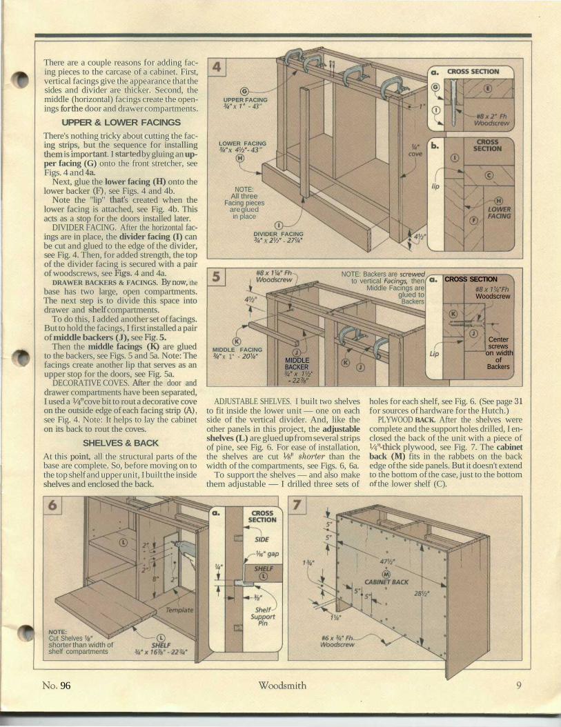
There are a couple reasons for adding fac-ing pieces to the carcase of a cabinet. First,vertical facings give the appearance that thesides and divider are thicker. Second, themiddle (horizontal) facings create the open-ings for the door and drawer compartments.
UPPER & LOWER FACINGSThere's nothing tricky about cutting the fac-ing strips, but the sequence for installingthem is important. I started by gluing an up-per facing (G) onto the front stretcher, seeFigs. 4 and 4a.
Next, glue the lower facing (H) onto thelower backer (F), see Figs. 4 and 4b.
Note the "lip" thaf s created when thelower facing is attached, see Fig. 4b. Thisacts as a stop for the doors installed later.
DIVIDER FACING. After the horizontal fac-ings are in place, the divider facing (I) canbe cut and glued to the edge of the divider,see Fig. 4. Then, for added strength, the topof the divider facing is secured with a pairof woodscrews, see Figs. 4 and 4a.
DRAWER BACKERS & FACINGS. By now, thebase has two large, open compartments.The next step is to divide this space intodrawer and shelf compartments.
To do this, I added another set of facings.But to hold the facings, I first installed a pairof middle backers (J), see Fig. 5.
Then the middle facings (K) are gluedto the backers, see Figs. 5 and 5a. Note: Thefacings create another lip that serves as anupper stop for the doors, see Fig. 5a.
DECORATIVE COVES. After the door anddrawer compartments have been separated,I used a W cove bit to rout a decorative coveon the outside edge of each facing strip (A),see Fig. 4. Note: It helps to lay the cabineton its back to rout the coves.
SHELVES & BACKAt this point, all the structural parts of thebase are complete. So, before moving on tothe top shelf and upper unit, I built the insideshelves and enclosed the back.
<§>-UPPER FACING3/4" x 1" - 43"
LOWER FACING3/4" x W - 43"
NOTE:All three
Facing piecesare gluedin place
DIVIDER FACING3/4" X 21/2" - 27'/4"
NOTE: Backers are screwedto vertical Facings, then
Middle Facings areglued toBackers
CROSS SECTION#8xV/4"FhWoodscrew
Centerscrews
on widthof
Backers
MIDDLE FACING3/4" x 1" - 20V4" MIDDLE
BACKER3/4"X V/2"
- 22%"
ADJUSTABLE SHELVES. I built two shelvesto fit inside the lower unit — one on eachside of the vertical divider. And, like theother panels in this project, the adjustableshelves (L) are glued up from several stripsof pine, see Fig. 6. For ease of installation,the shelves are cut Vs" shorter than thewidth of the compartments, see Figs. 6, 6a.
To support the shelves — and also makethem adjustable — I drilled three sets of
holes for each shelf, see Fig. 6. (See page 31for sources of hardware for the Hutch.)
PLYWOOD BACK. After the shelves werecomplete and the support holes drilled, I en-closed the back of the unit with a piece ofV4"-thick plywood, see Fig. 7. The cabinetback (M) fits in the rabbets on the backedge of the side panels. But it doesn't extendto the bottom of the case, just to the bottomof the lower shelf (C).
NOTE:Cut Shelvesshorter than width ofshelf compartments
No. 96 Woodsmith

DRAWERS, DOORS & TOPWith the shelvesand back installed, Imoved on to thedrawers. But firstthere needs to besome way of attach-ing the drawerhardware (glides).
MOUNTING RAILS.
Ordinarily, drawerglides are attacheddirectly to the sidesof a cabinet. But onthis project thafs
not possible — the sides are "recessed" be-cause of the vertical facings on the front ofthe cabinet sides.
So I came up with a different method ofattaching the drawer glides. If s a system ofmounting rails — strips of wood suspendedbelow the stretchers (E), see Fig. 8.
After cutting the mounting rails (N) tofinished dimensions, they can be installedinside the case, see Fig. 8a.
Note: In order for the drawers to fit prop-erly, the rails are installed flush to the insideedges of the facings on the front of the case.
DRAWERS. After the mounting rails havebeen installed, I moved on to the drawers.All the drawer parts, the front/backs (O)and the sides (P), are cut from VSrf-thickstock, see Fig. 9.
Note: There are three dimensions to con-sider when cutting the drawer parts. First,the drawer glides I used require W clear-ance on each side of the drawer, see Fig. 9a.
The details of the drawer joint are the sec-ond dimension that affect the length of thefronts and backs (O), see Fig. 9b.
And third, all the drawer parts are cut towidth to allow a Vi6M gap at the top and bot-tom, see Fig. 9a.
DRAWER JOINTS. After the drawer partshad been cut to finished dimensions, I cutthe tongue and dado joints that hold theparts together, see Fig. 9b.
Next, to hold the drawer bottoms, I cut agroove along the inside face of each drawerpart, see Fig. 9c. Then, the bottoms (Q)can be cut to fit in the grooves.
FALSE FRONTS. The full-extension drawerglides I used on this project need to be hid-den when the drawers are closed, see Fig.9a. That's the job of false fronts, see Fig. 10.
The false fronts (R) are cut from W-thick stock to fit the drawer openings withan even (Vie") gap all around, see Fig. lOa.
Then two holes can be drilled for a pair ofwood knobs, see Fig. lOa.
DRAWER GLIDES. Before the drawers canbe installed in the case, the drawer glidesneed to be attached. (Refer to page 16 formore on this.)
After the drawers are installed, the falsefronts can be attached, see Figs. 10 and lOa.
#8x2" FhWoodscrew
DRAWERMOUNTING RAIL
3/4"x2" - 17"
NOTE: EachMounting Rail
is installedwith four
screws
Mount inside Rails (N)flush to outside edqeof Divider Facing (ij
CROSS SECTION(Back View)
Mount outside Rails (N)flush to inside edge
± of Vertical Facing (A)
SWFDIVIDER FACING (T) VERTICAL FACING
(1/4"-thick plywood)v x^^X BOTTOM efflxX/4"- NOTE: Drawer Front, Back,
^^ (W-thirlf nl\AA/nnri] ^^f^ / =.«,-/ CiW«r .̂̂ « <-i.tand Sides are cutfrom 1/2"-thick pine
O. V2"-thick — ~^drawer glide —*
NOTE:Glide isflush withbottomof Rail-—
V
i®
TOPVIEW
Cut grooveto matchthickness
of plywood
/H. CROSS SECTION
FALSEDRAWER
FRONT3/4" x 43/8" - 20W
Drill'/2W ho/e%" c/eep/or drawerknob
Vie"
FALSEDRAWER
FRONT
I
10 Woodsmith No. 96

The doors that enclose the bottom of theHutch are made in the traditional way -solid wood panels inside solid wood frames.
RAILS & STILES. I started the doors by cut-ting the frame pieces. Two vertical stiles(S) and two horizontal rails (T and U) foreach door, see Fig. 11.
Note: The bottom rails (U) are wider thanthe top rails (T).
After the frame parts have been cut,grooves for the panel can be cut on the in-side edges, see Fig. lla.
Then, stub tenons are cut on the ends ofthe rails to fit in the grooves, see Fig. lla.
RAISED PANELS. The panels (V) insidethe frames are made from V^'-thick pine.And to allow for expansion and contractioninside the frames, the panels should be cutVs" smaller in both directions than the dis-tance between the bottoms of the grooves,see Fig. 11.
After the panels have been cut to size, Iused the table saw to cut a bevel all aroundthe front face. This creates a decorativeraised field, see Fig. lib. (For more on this,refer to page 16.)
Now, all the doors can be assembled withglue in the corner joints only, not aroundthe panel. It must be free to "float" when itexpands and contracts.
HINGES & KNOBS. Before the doors canbe installed, mortises are cut for the hinges,see Figs. 11 and lie.
Shop Note: I cut the mortises in the doorstile Vs" deep—enough to create a Vie" gapbetween the door and the case when thedoor is installed. This way, mortises don'tneed to be cut in the case.
After installing the hinges on each door, Idrilled a 5/8M-deep hole on the front for thedoor knob, see Fig. 11. (They're the sameknobs used on the drawers, refer to Fig. lOa.)Then the knobs can be glued in the holes.
Finally, the doors can be installed insidethe case and adjusted for an equal Vie" gap
11
2"x13/8"Butt Hinge —
10" -
2V2"
27%"
See Detail cfor cuttingmortise s. -
DoorKnob
DOOR RAIL, TOP%" x 21/2" - 53/4"
(make four)
NOTE: Cut all door partsto allow Vie" gap aroundinstalled doors
KDDOOR STILE
3/4"x2V2"-27%"
(make eight)
DOOR PANELV2" x 5%"
- 151/4"(make four)
DOOR RAIL, BOTTOM3/4" x 4V2" - 53/4"
(make four)
around and between them.DOOR CATCHES. Next, to secure the doors
in the closed position, a magnetic catch is in-stalled inside the case, see Fig. 12a. And astrike plate is attached to the inside face ofthe door stiles, see Fig. 12a.
TOP. I completed the lower cabinet bymaking a top for the unit, see Fig. 13.
The top (W) is glued up from 1 W-thickstock. After the top had been cut to finishedsize, I routed a decorative bullnose profilearound the sides and front (but not alongthe back), see Fig. 13a.
Finally, I attached the top to the case us-ing woodscrews through oversize (Vie")shank holes in the stretchers, see Fig. 13.
NOTE: Install Top flushwith back of cabinet ^ ®CABINET TOP
V/4ttx183/4u-3/i6"-dia.countersunkshank hole-
FIRST: Installdoors incabinet
#8xV/2" .Fh Woodscrew
NOTE: Don'tround overback edge
of TopMagnetic DoorCatch
RouterStable
fence72" round-over bit
SECOND: Install door catch \\and strike plate, see Detail a.
No. 96 Woodsmith 11

UPPER CABINETAt this point, thelower cabinet iscomplete. By add-ing an upper cabi-net, the project be-comes a hutch.
FACINGS & SIDES.The upper cabinetis built much likethe lower one.First, vertical fac-ings (X) are cut andglued to the sides(Y), see Fig. 14.
(The same tongue and groove joint used onthe lower unit is used to connect the facingsto the sides, see Fig. 14a.)
Then a stopped cove is routed on the frontedges of the facings, see Fig. 14.
The main difference between this upperunit and the lower unit is in the joinery atthe back. Instead of a rabbet, the sides forthis unit have a groove for accepting theback assembly, see Fig. 14b.
BACK RAILS. To enclose the back of theupper unit, there are a series of back slats,see Figs. 15 and 18. These are held in placeby a pair of rails that connect the sides (Y)at the top and bottom, see Fig. 15.
Note: The rails are cut from 1W'-thickstock, but the upper rail (Z) is narrowerthan the lower rail (AA), refer to Fig. 19a.
After cutting the rails to finished dimen-sions, I cut the joints on each piece. Thisconsists of a short offset tenon mat fits intothe groove in the sides, see Figs. 16 and 16a.
The other joinery on the rails is a simple
14 See Detail b.
SIDE
443/4
VERTICALFACING
r— See Detail a.
SIDE
443A
u NOTE: Cut tongueto fit groove
1 2W
^
NOTE: Rout %"stopped cove on bothfront edges of Facings
rabbet that accepts the back slats, see Figs.17 and 19a.
COVES. Finally, I routed a W stopped coveon the bottom edge of the upper rail and thetop edge of the lower rail, see Figs. 15,19a.
BACK SLATS. The back of this unit is en-closed with thirteen back slats. All the slatsare cutto the same length (413/i6M) from 3/4M-thick pine, see Fig. 15. The only thing that'sa bit unusual here is the width of the slats.
The two outside slats (BB) are wider(3%") than the eleven inside slats (CC,3V£"). Thafs because the tongues on the out-side slats are hidden. (The idea is for all theslats to look the same after they're installed.)
After cutting the slats to finished dimen-sions, a groove is cut on both edges of theinside slats (CC). This is for a spline thatkeeps the slats aligned, see Figs. 18 and 18a.
Then, an identical groove is cut on just the
UPPER BACK RAIL11/2"xlV2"-
BACK SLATS(refer to Fig. 18)
LOWER BACK RAILV/2"x3V2"-47%"
' stopped cove
/-
2a.SeeFig. 17
i
SIDE
«D\^,
SeeFig. 16
Cut tongueson both ends ̂of Upper and /Lower Back Rails
-J-^-] V/2"
rill
OUTSIDEBACK SLAT
Note grain directionon Splines
12 Woodsmith No. 96

inside edge of the outside slats (BB). Fi-nally, a rabbet is cut on the outside edge ofthe outside slats, see Figs. 18 and 18a.
CHAMFERS. Then, before the slats can beinstalled, I routed a decorative chamfer onboth edges of the inside slats, but only oneedge of the outside slats, see Fig. 18a.
SPLINES. Now that the slats are cut, thereneeds to be a way to keep them all aligned.That's the job of splines, see Fig. 18.
The splines (DD) are pieces o W-thickpine ripped to width (W) so they fit in thegrooves in each of the slats, see Fig. 18a.
ASSEMBLY. Now the upper unit can be as-sembled. To do this, I found it easiest to firstattach the slats between the top and bottomrails. Don't forget to install a spline (with noglue) between each of the slats.
I started by screwing the outside slats tothe rails so the edge of each outside slataligns with the end of the tenon on the rails.
Then attach the inside slats so there's aconsistent-size (Vie") gap between the slats.
With the back slats and rails assembledas a unit, the sides of the cabinet can beglued on, see Fig. 19.
VALANCE & TOPNow the side can be connected across thefront by a strip called a valance.
VALANCE. The valance (EE) starts out asa long strip cut to fit between the vertical fac-ings, see Fig. 20. Note: When measuring forthe valance, the back unit must be square.
To lay out the arch shape, first make pen-cil marks to indicate the ends of the arc, seeFig. 21. Then make a mark to indicate thetop of the arc. Now, connect the marks usinga thin stick as a guide for the pencil. (Nailshold the stick while the curve is drawn.)
Next, the arched profile can be cut on theband saw or sabre saw. Then sand the archsmooth and rout a decorative cove along thebottom edge, see Fig. 21a.
SCREW BLOCKS. There's a simple way toattach the valance between the vertical fac-ings. It involves a pair of V^"-thick screwblocks (FF) that are glued and screwed tothe back of the facings. Then the valance isscrewed to the blocks, see Figs. 20 and 20a.
TOP. The top (GG) of the upper unit isjust like the top of the lower unit It's gluedup from 1 V£"-thick stock then cut to size, seeFig. 22. Note: The edges of this top are leftsquare (no bullnose profile).
The top can now be screwed to the sides(Y), back rail, and valance, see Figs. 22 and22a. Note: There should be an equal (1")overhang on the sides and front but no over-hang at the back.
MOLDING. The edges of the top aren'trouted, but there is a decorative detail. It'sa strip of molding (HH) attached below thetop with 4d finish nails, see Figs. 22 and 22a.
19 OUTSIDE SLAT(BB
NOTE:Outside Slatsare attached with fourscrews each; Inside Slats areattached with two screws each
0. CROSS SECTION
#8xV/4H-Fh
Wood-screw
20 r<£S>?S^XBL^ glued and fa. CROSS SECTION1/2 x3 -31/2 ^.screwedto back
(Both ends)
(£*>—VALANCE
3/4" x 3V2" - 43"
VALANCE
<£!>SCREWBLOCK
•,|
4V2*V/2"
"5 »'"OrH
COVEMOLDING3/4" X 5/8" -
84" (rgh.)
NOTE:MiterCoveMoldingto fit "aroundTop
Roundover)#8x2V2"FhWoodscrew
No. 96 Woodsmith 13

TOP SHELVESThe upper half ofthe Hutch is almostready to be placedon the lower half.But there's onething to do first
SHELF HOLES. Iplanned to add twoshelves to the up-per unit. And Iwanted each shelfto be adjustable. Sobefore attachingthe upper unit to
the lower case, I drilled twelve holes in eachside for shelf support pins, see Fig. 23.
Shop Note: I used the same trick used forthe shelf support pins on the lower unit —a piece of Masonite as a template for drillingthe holes, see Fig. 23.
FIGURE-8 FASTENERS. Now the upper unitcan be attached to the lower unit. To do this,I first installed a pair of "Figure-8" fastenerson the bottom end of each vertical facing(X), see Fig. 24.
In order for the upper unit to pull tight tothe lower unit, the fasteners must be re-cessed into the facings. This is done by drill-ing a shallow hole on the bottom of each fac-ing, see Fig. 24a.
Shop Tip: Each hole should be drilledslightly off center of the facing. To keep thedrill bit from wandering, I used a piece ofscrap clamped to the facing as a guide forthe drill bit, see Fig. 24a.
After the fasteners have been screwed tothe facings, the upper unit can be attachedto the lower unit, see Figs. 25 and 25a. Thenit can be secured at the back, too.
CONNECTING CLEAT. The method I usedto attach the top unit to the bottom unit atthe back is fairly straightforward. It's a cleatthaf s screwed across both units, see Fig. 26.
After cutting the connecting cleat (II)to finished size, I chamfered the edges, seeFig. 26a. Then the cleat can be screwed tothe back of the upper and lower units.
SHELVES. The last part of this project isone of the easiest — building two shelves(JJ) to fit in the upper unit, see Fig. 27.
Note: Because these shelves have alonger span than the shelves in the lowerunit, they're made from IV^'-thick pine.
After the shelves have been cut to fit in-side the top unit, I next used a cove bit torout a decorative edge along the front ofeach shelf, see Fig. 27b. This ties theshelves in with the rest of the project.
Finally, I routed a pair of grooves alongthe top of each shelf to act as plate holders.For this, I switched to a core box bit in therouter table, see Figs. 27 and 27a. Therouter table fence acts as a guide for routingthe plate grooves—two different setups areall that's needed. Q
Notch allows templateto clear Lower Rail
Bottom end of' Vertical Facing
Center upper unit on-lower unit
upperunitalignswithback oflowerunit
a.?S x 7 "
Fh-A/nnHfVUfJU
screw
^^
<
SZ
1j•""'̂ ""'̂ x.
Figure-8 fastener--^
NOTE: CenterCleat on width
of Hutch
a. CROSSSECTION
^#8x11/4HFh
Wood-screw^-
I 1(14=
t . < » '
(77)
.̂. — ̂ V
,
»^7/&" chamfer
>l
(AA)
»nr̂ , s \
^7-
-TT> (W),uXAX> v»j//
y
27NOTE: Shelf is cutW smaller thanopening in upper unit
Plate grooves arerouted 3/ie" deepwith W core box bit
SHELF
NOTE: Rout cove on front edges only
14 Woodsmith No. 96

BLOTCH-FREE STAININGPine can be a stubborn wood tostain. The problem is that thepores of the wood alternatefrom large, open pores to small,dense ones. These variations af-fect the way a stain is absorbedinto the wood. Most of the time,the result is ugly blotches.
That's why, in the past pinefurniture was often finishedwithout a stain. Or it waspainted. But for the CountryHutch in this issue, I wanted the
look of an aged piece of pine —without waiting for it to developnaturally. Using a honey-col-ored stain was the answer. Butto avoid blotches, I first treatedthe wood with a stain controller.
STAIN CONTROLLER. The typeof stain controller I used is athinned-down oil that pene-trates all the pores of the wood.So when the stain is applied, itpenetrates the pores less deeplybut more evenly. And more even
penetration means less blotch-ing. (Think of applying a staincontroller as similar to searing athick steak on both sides beforegrilling it.)
Stain controller is applied likean ordinary coat of oil finish.Wipe it on liberally, let it soak in,then wipe off the excess. Thekey to avoiding blotches is to be-gin applying the stain rightaway, before the stain controllerhas dried completely.
TOP COAT. After the stain hasdried completely (in about 24hours), you can apply the topcoats of finish. (I used two coatsof wiping varnish, see page 31.)
Note: After the stain hasdried, you may notice that thewood has grown some "whisk-ers." These are small fibers thatwere raised by the coat of stain.The way to eliminate whiskers isto apply the first coat of varnishwith 600-grit wet/dry sandpaper.
CUTTING DIAGRAMV2" x W - 96 (6.2 Bd. Ft.) V2"x7W-72" (3.6Bd.Ft)
o
p
o
' 1o
p
oII
" K.,,,„, .̂ :
V V V V m<1 x 6 (W x 5W) - 8' (4 Bd. Ft.)
1 x 8 (3/4u x 7W) - 6' (4 Bd. Ft.)
| u | u I u I u }//,.J r / . /' / / / / / / /
1 x 6 (%" x 51/2") - 8' (4 Bd. Ft.)
IS | S
sS
QS
TT
' /
2x6(1 V2"x 5V2") - 5' (4 Boards @ 5 Bd. Ft. Each)
" 3?1 x 8 (3/4" x r/t") - 8' (3 Boards @ 5.3 Bd. Ft. Each) 2x6(1 V2"x 5V2") - 5' (3 Boards @ 5 Bd. Ft. Each)
B G B/
D /^ ^ , ; , \/f
GG
1 x 8 (3/4" x r/4") - 8' (3 Boards @ 5.3 Bd. Ft. Each) v-_ K2x6(1 V2"x5V2") - 5' (5Bd. Ft.)
c L L/ /
''/
AA
1 x 8 (3/4n x 7W) - 8' (5.3 Bd. Ft.)
I '
1 x 8 (3/4" x 71/4") - 8' (5.3 Bd. Ft.)
1 x 8 (3/4" x 7W) - 8' (2 Boards @ 5.3 Bd. Ft. Each)
CC
CCCC
CC
x 48" x 48" Plywood
1 x 8 (3/4" x 71/4") - 8' (5.3 Bd. Ft.)
CC CCCC EE
7 x 8 (3/4n x 7W) - 8' (5.3 Bd. Ft.)
BB
7 x 7 0 (3/4" x 91/4") - 8' (6.7 Bd. Ft.) DO
2x12(11/2" x 11 W) -8' (16 Bd. Ft.)
JJ
JJ
JJ
JJ n//////
No. 96 Woodsmith 15

S O M E T I P S F R O M O U R S H O P
Shop NotesSHARPENING A V-PARTING CHISEL• Compared to a regular chisel,sharpening a carving tool is a bitmore involved. Especially onelike the V-parting chisel used tocarve the pattern on the NoteBoard, see pages 18 and 20.
SHARPENING THE FACES. Fora V-parting tool, you begin justlike you're sharpening a regularchisel with the beveled facedown. But because a V-partingtool has two sides that come to-gether at an angle, both outsidefaces must be sharpened, seeFig. 1. Note: I use a medium-gritoil or water stone.
To do this, hold the chisel at
about a 20°-25° angle and moveit back and forth along thestone. To keep the angle consis-tent, use short strokes.
The trick here is to sharpenboth sides evenly. I count out afew strokes on one side, then flipit over and do the same numberof strokes on the other.
What you're looking for is asmall burr that runs completelyacross the inside face on eachside. To keep this burr frombreaking off and forming aragged edge, I remove it bydragging the inside face againstthe corner of a leather strop.
REMOVING THE HOOK. Whenthe burr has been removed,there's still a small "hook" left onthe outside corner, see Fig. 2a.If you don't remove this hook,the tool will be hard to control.
Removing the hook isn't diffi-cult. Just gently roll the tip of thechisel back and forth across amedium stone, see Fig. 2.
But be careful. You don't wantto remove too much metal. In-stead of just grinding away thehook, you'll create a tiny divot,which also prevents a clean cut.(If this happens, square up theedges and start again.)
POLISHING. The last step iscritical to getting the tool reallysharp. It's polishing the chiselwith a leather strop (or buffingwheel if you have one). Polish-ing removes the tiny nicks in theedge where the outside and in-side faces come together. Re-moving these nicks makes thetool much sharper.
To do this, add a little jew-eler's rouge to the leather andrepeat the sharpening steps topolish the edge, see Fig. 3. Don'toverdo it though. You canchange the angle of the bevel ifyou strop it too much.
Concentrate sharpening. on end of bevel >
FIRST:Sharpen bevelon outside facesSECOND: Removeinside burr
Polish edgeswith leather strop
Gently rollchisel to
remove hook
Apply jeweler s rougeto leather strop
DRAWER GLIDE INSTALLATION• I wanted to make the CountryHutch on page 6 as traditional-looking as possible. But therewas one modern innovation Iwasn't going to leave out: full-ex-tension drawer glides.
Wood glides look traditional,but they also tend to bind undera heavy load, such as a drawerfull of silverware. (This is espe-cially true of pine.) Full-exten-sion glides open smooth andalso make it easy to get at thecontents in the back of a drawer.
Like any drawer hardware,full-extension glides have to be
mounted level with each other.But this can be a little trickierthan with other glides. That'sbecause the edges are typicallyrounded. So it's hard to linethem up accurately.
With the Country Hutch themounting rails for the drawershang from the top and aren'tpart of the sides. So I clamped ascrap piece to the bottom of therails to create a little ledge, seeDrawing. When the glides wereset in place, they were perfectlyflush with the bottom of the railsand level to each other.
16 Woodsmith No. 96

SQUARE CORNERS• Most of the time when youadd facing strips to a case, thecase has already been built.Adding the facing is simply amatter of gluing and clampingthe strips in place.
But I built the Country Hutcha bit different. I added the verti-cal facings to the sides beforebuilding the case. And instead ofbutting them, I cut tongue andgroove joints to add strength
and keep these pieces alignedwhen clamping them together.
But keeping pieces alignedisn't the same as keeping themsquare. You'd think that whenusing a tongue and groove joint,there wouldn't be any need toworry about the squareness ofthe assembly. If the joint is cutright, the tongue and grooveshould "lock" the pieces square.
But surprisingly, this isn't the
1 Facing
Clampingpressuretends topull joint
out ofsquare
case. The problem isn't with thejoint — it's with the clamps. Ifthe clamps aren't perfectly cen-tered on the joint, they tend toforce the facing piece out ofsquare, see Fig. 1.
There are two solutions. Oneis to make sure the clamps arecentered perfectly. But this iseasier said than done. Espe-cially on the Hutch's long sidepanels and facings.
A better way to keep thepieces square is to use clampingblocks, see Fig. 2.1 clamp thesesquare blocks into the corner ofthe assembly. So the assembly isautomatically pulled up squareagainst the blocks.
Note: I cut off the inside cor-ner of each block. This way, anyexcess glue that's squeezed outwon't make the clamping blocksa permanent part of the Hutch.
Use dampingblock to holdjoint square
CUTTING RAISED PANELS SAFELY• I was just getting ready to cutthe raised panels for the doorson the Country Hutch when Iheard "the voice." You know, theone in the back of your head thatsays, "This cut might be danger-ous. Don't try it."
I stepped back to look at thesetup a second time. Cutting thelong sides of the panel wasn't aproblem. But cutting the shortends, which are less than 6"wide, wasn't a good idea.
Riding on the short ends, the
panel just wasn't stable — espe-cially when you consider there'sonly 3/i6M between the fence andthe blade for the piece to ride on.(Not to mention that about halfof this 3/i6" includes the openingin the table saw insert.) Plus, tohold the piece tight against therip fence, my hands would haveto pass close to the blade.
I didn't really want to take thetime to build and set up a specialjig. But I wasn't going to attemptto cut the ends of the raised pan-
7
— frn.i.nmm_jiiyn«»i
Aux.Fence
\
:x\;N \
, \ ^V
l\| 1 |N
1 PI1 ;,,. r
sra>t- '
dli
e
N \\ \ vJ
uiulu&uuT
/̂fHand-screws
L._/_
supporta tall
panel
1lMa, \ .,.„.._ ^
els without some extra support.Fortunately, the solution I cameup with was quick and simple.
First, I attached a taller auxil-iary fence to the rip fence, seedetail in Drawing below. Then Iset the panel on the saw andheld it tight against the fence.
While holding it in place, Iclamped a couple wood hand-
screws to the panel so theyrested flat on top of the auxiliaryfence, see Drawing below.
The idea here is simple. In-stead of trying to balance thepanel against the fence, I usedthe handscrews for added sup-port. They ride along the top ofthe auxiliary fence as the panelmoves past the saw blade.
SANDING BEVELS
Sand to removesaw marks
^ Cut edge of sanding( block to match angle\ of bevel
Sandpaper
When cutting raised panelswith the table saw, you oftenend up with saw marks left bythe blade. The quickest way toremove these marks is to use a
sanding block. It's a good ideato bevel the edges of this blockso it squares up the shouldercreated by the raised field ofthe panel, see detail above.
No. 96 Woodsmith 17
W E E K E N D P R O J E C T
Note BoardKeep a memo pad and pen
within easy reach.
You know how it goes. When the phone call is really important,you can't find anything to write with (or write on). This Note
Board solves that problem. Besides holding a standard officecalendar (8^" x 11"), it also has a shelf for a note pad and pen.
The Note Board is a quick weekend project There are only fivedifferent parts, and the joinery is quite simple. This means you canspend more time on the fun part—carving the wheat pattern alongthe top. (For more on this, see page 20.)
Of course, you don't have to carve the pattern. Instead, you couldstencil it or use a wood burning tool. But if you do choose to carvethe accent design, then read the carving article on page 20 beforeyou begin building the Note Board.
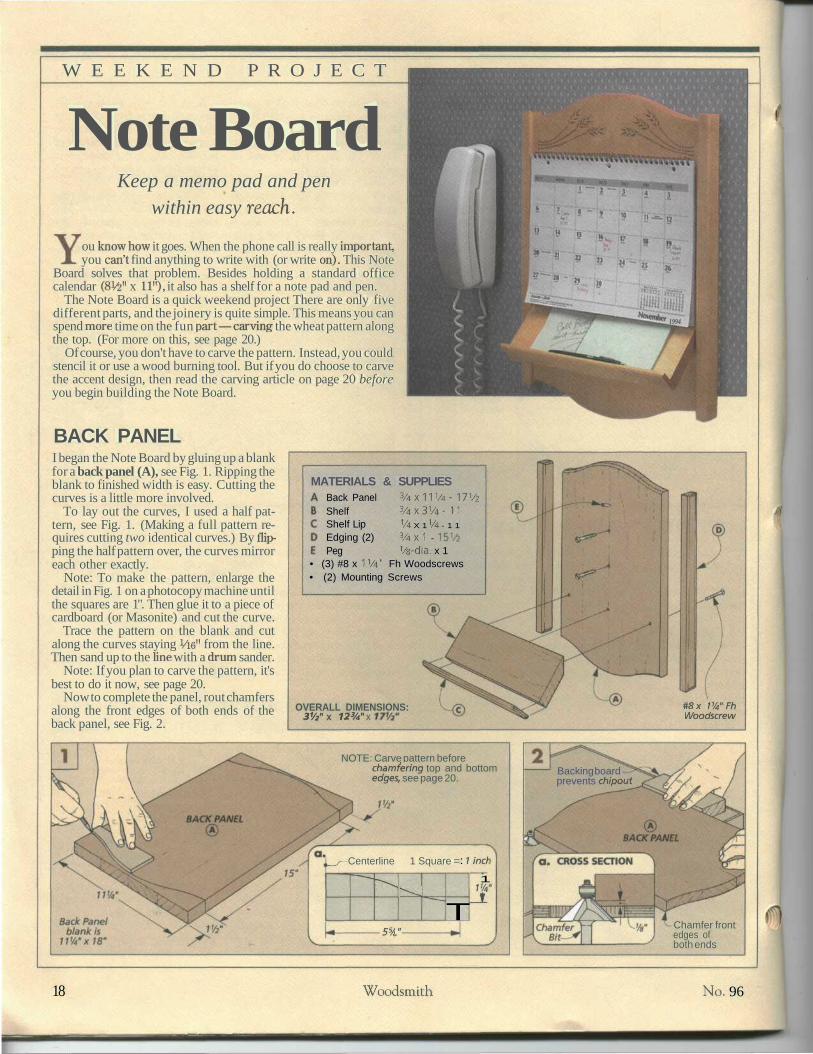
BACK PANEL
1994
I began the Note Board by gluing up a blankfor a back panel (A), see Fig. 1. Ripping theblank to finished width is easy. Cutting thecurves is a little more involved.
To lay out the curves, I used a half pat-tern, see Fig. 1. (Making a full pattern re-quires cutting two identical curves.) By flip-ping the half pattern over, the curves mirroreach other exactly.
Note: To make the pattern, enlarge thedetail in Fig. 1 on a photocopy machine untilthe squares are 1". Then glue it to a piece ofcardboard (or Masonite) and cut the curve.
Trace the pattern on the blank and cutalong the curves staying Vie" from the line.Then sand up to the line with a drum sander.
Note: If you plan to carve the pattern, it'sbest to do it now, see page 20.
Now to complete the panel, rout chamfersalong the front edges of both ends of theback panel, see Fig. 2.
MATERIALS & SUPPLIESBack PanelShelfShelf LipEdging (2)Peg
3 / 4 X 1 1 V 4 - 17V23 /4X3 1 /4- 111/4 X 1 1/4 - 1 13 / 4 X l -
Vs-dia. x 1• (3) #8 x 11/4" Fh Woodscrews• (2) Mounting Screws
OVERALL DIMENSIONS:31/2" x 123/4" x
#8x VA'FhWoodscrew
NOTE: Carve pattern beforechamfering top and bottomedges, see page 20.
__/— Centerline 1 Square =
"**t^ -̂*.^\K^
**u**»-*.
: 1 ind
TC5/ »
1
_!i
Backing boardprevents chipout
Chamfer frontedges ofboth ends
18 Woodsmith No. 96

SHELFA simple shelf is the first piece to be addedto the back panel. If s attached at an angleand has a lip for a pen and a note pad.
Start by cutting the shelf (B) to roughsize, see Fig. 3. (Later, one edge will be bev-eled, but it's easier to clamp the lip to theshelf while it still has square edges.)
Now, make the shelf lip (C) and glue itto the edge of the shelf, see Fig. 3. Once it'sdry, the lip can be chamfered, see Fig. 3a.Routing this tiny piece is much safer nowthat it's been glued to the shelf. This way, theshelf can be used as a handle.
Next, I tilted the table saw blade to 45° andripped the shelf to final width, see Fig. 3b.
SPOT GLUINGTo attach the shelf to the back panel, you
can't just glue it in place. The problem is thegrain on the shelf runs across the grain onthe panel. The panel naturally expands andcontracts across its width, and if the shelf isglued in place, this movement will eventu-ally cause the joint to come apart.
The solution is to attach the shelf withscrews, see Fig. 4. To do this, I first drilledthe shank holes oversize. (This allows thepanel to expand and contract.) Then I spotglued the shelf to the panel, see photo atright The glue temporarily holds the shelfin place while the pilot holes are drilled andthe shelf is attached.
A To position the shelf, all you need aretwo drops of glue and some hand pres-sure. Later, it can be secured with screws.
Chamferaroundfront
face of
FIRST:Drill oversize,countersunkshank holesin Back Panel
SECOND:Spot glueshelf to Panel(See box above)
THIRD:Secure pieceswith screws
SHELF BACK PANEL
EDGING & PEGThe Note Board is almost done. All that's leftare some decorative edging pieces and apeg to hang the calendar.
First cut two pieces of edging (D) to size,see Fig. 5. Then chamfer the edges, see Fig.5a (Note: Not all edges get chamfered.)
Now glue and clamp the edging to thepanel, see Fig. 5b. Shop Tip: Let the glue seta bit before you attach each piece. This way,the edging won't slide around.
The last step is to drill an angled hole forthe peg that holds the calendar, see Fig. 6.
For the finish, I applied a coat of MinwaxWood Conditioner, then two coats of theirColonial Maple stain. For a top coat, I usedGeneral Finishes' Royal Finish, see page 31.
To mount the Board, I simply screwed itto the wall, refer to the Exploded View. Q
BACKPANEL
I
SHELF
Vs" chamferon both faces(except back,inside edge,see detail a.)
a. TOP VIEW
75'/2"
y EDGING(make two)
—Do notchamfer
Drill-dia.
- holeat 10°angle,
'/4" deep
No. 96 Woodsmith 19

W O O D W O R K I N G T E C H N I Q U E
Accent CarvingMost people I've shown thiscarving pattern to have beeneager to give it a try. The simplewheat pattern really looks "do-able" — and it is. In no time atall, you'll be able to master a fewsimple carving techniques soyou can add a decorative accentto a project.
Carving this pattern doesn'trequire a large initial invest-ment either. You only need one$10 carving chisel (for sources,see page 31) and a sharp utilityknife. Plus some scrap pieces ofwood to practice on.
WOOD SELECTION. But beforegetting started, I should mention somethingabout the kind of wood to use. Choosing theright type of wood is just as important aschoosing the right tool.
The perfect wood for this type of carvinghas two qualities. First of all, it should besoft. This makes it easier for you to controlthe chisel and make the cuts.
The second quality to look for is a tight,straight grain pattern. (Or better yet, no vis-ible grain pattern at all.) In fact, woods tra-ditionally used for carving, like basswood,have barely noticeable grain patterns.
PINE. For the Note Board, I decided touse pine. Pine can also be a good carvingwood. But you have to choose the right
boards. To look at the NoteBoard on page 18, you mightthink it was a good project to usesome scraps of pine lyingaround the shop. But that's notnecessarily the case.
Some pieces of pine are a lotharder than others. The harderboards can be identified by theirdark grain patterns. This darkergrain (called latewood) containsresins that make it much harderthan the lighter and softer early-wood. Carving through late-wood is difficult. So when youpick out your pieces, pick outthe softest boards with lightest
grain pattern you can find. The result will bea crisp and clean carving.
PROCEDURE. Once you've selected thewood, the procedure is simple. First, trans-fer the pattern onto the panel blank, see boxbelow. Then carve the design. (But beforestarting on the real thing, it's a good idea topractice the technique first.)
TRANSFERRING THE PATTERNIf you're more artistic than I am, you won'tneed a pattern to do this carving. It's sim-ple enough to draw freehand (or you couldeven create your own design). But just incase, there's a half-size pattern below.
To use this pattern, you'll need to en-large it on a photocopier until it's IIWwide — roughly 200%. (Or you can ordera full-size pattern, see page 31.)
To get the pattern on the wood, Ithought about using carbon paper. Butcarbon paper leaves a waxy or greasy resi-due that's hard to erase.
Instead, I used transfer paper. (See page31 for sources.) Transfer paperworks justlike carbon paper, but better. It leaves"dry" lines you can erase easily.
To transfer the pattern, first tape thephotocopy to the panel so the curve on thepattern lines up with the curve on the topof the panel, see photo at right. Then slipthe transfer paper between the patternand the wood with the dark side down.Now trace the pattern with a pencil. Thetransfer paper leaves a light line whereveryou push down with the pencil.
{ To get the pattern onto the blank, I usedtransfer paper. It works just like carbonpaper but erases much easier.
NOTE:Enlarge pattern untilit's full size (HW wide)
Use top curveto position pattern
on panel
20 Woodsmith No. 96

TECHNIQUEI tried carving this pattern with all sorts ofknives and chisels. The best tool was an in-expensive V-parting chisel. (For sources,see page 31.) Its palm-handle grip is com-fortable and easy to control.
There are two basic cuts needed to carvethe wheat pattern. The first is a long shallowcut for the stalks, see Fig. 1.1 found it easiestto hold the chisel at a low angle with onehand and guide it with the other. But don'ttry to make the entire cut all at once. If shard to stop the cut cleanly. Instead, carvemost of the stalk in one direction. Then
To keep cuts even,hold chisel at
consistent angle
Complete cut fromopposite direction
come back from the otherdirection to finish it off.
For the stalks, the im-portant thing is to keep the lines smooth andeven. To do this, the carving tool must beheld at a consistent angle. If you want theline to widen (as on the ends of the stalks),just raise the handle a little. Then the chiselwill dig in deeper and make a wider cut.
The second cut shapes the kernels ofwheat. This is also a two-step process, seeFig. 2. Start by pushing the tool into thewood about half the length of the kernel.
Then repeat thiscut coming from the opposite direction. Asingle oval-shaped chip will pop out wherethe two halves meet. But keep the angle ofthe tool the same for each cut, see Fig. 2a.You'll get a cleaner carving.
There's one last detail you may want to in-clude. To make the kernels more realistic,I scored a simple line through each with autility knife, refer to Step 5 below.
FIRST: Push tool inhalf the lengthof the kernel For the cleanest results, //
the chisel should beangled the samewith each cut j \ /
SECOND: Completesecond half of cutfrom opposite direction
STEP-BY-STEPYou might be tempted just to "jump in" andstart carving this wheat pattern. But in or-der to avoid chipout, it's important to followa certain sequence.
I started with the stalks. This curved cutis the hardest to control. And if you carvethe ties before the stalks, there's a goodchance the wood will chip out
Next, I worked on the ties that cross thestalks. This is also a two-step process — if stoo easy to "overshoot" the cut
Finally I cut the kernels of wheat. Thereisn't any particular sequence here. Butmake sure you don't cut the kernels tooclose to each other. Any closer than Vs", andthe pine may chip out. Q
1 To carve the wheat, first transfer thepattern to the panel blank. Then begin
by cutting the stalks. But don't cut thewhole stalk at once. Stop about 1" short.
2 Complete the stalk by starting from theopposite end and connecting with the
first cut. For an even line, be careful to holdthe chisel at the same angle as before.
3 With all the stalks complete, next carvethe ties. Again, cut these from both di-
rections. This gives you better control of thedepth and length of the cut.
4 Carving the kernels is the next step.What you want is to cut a single, oval-
shaped chip. This is best done in two steps,keeping the angle of the chisel consistent.
5 If you would like to add "beards" to thekernels of wheat, simply take a sharp
utility knife and make a scoring cut throughthe center of each kernel.
No. 96 Woodsmith 21

I N T H E W O O D S M I T H S H O P
Sanding TipsThe more you know about the process,
the less time it will take.
How often do you hear someone say,"You did a great job of sanding that
project"? That's the problem with sanding.For something that takes so much time andcreates so much dust, it goes unnoticed.
Of course, if you did a poor job of sanding,it would get noticed. That's because thereisn't any finish that will hide a poor sandingjob (except maybe paint). Instead, a finish
will emphasize any irregularities or blem-ishes on the surface of the workpiece (likescratches and glue).
With all the power sanders and handsanding products available these days, youmight be tempted to think another tool willsolve your sanding headaches. But whilethese tools can help with the elbow grease,the process is still the same. And under-
GETTING STARTED
standingthis processwill savetime whether you're using a power sanderor just a plain old sanding block.
The following are a few notes and tips wethought you'd find helpful. They describehow we get the sanding job done in the leastamount of time. With the best results.
Many woodworkers will put offsanding for as long as possible.But after the project has been as-sembled, the sanding becomesmuch more difficult. So I alwaystry to get started sanding assoon as possible.
For example, it's much easierto sand a large panel when it canbe laid flat, see Tip 2 below. Orto sand a raised panel before it'sassembled in its frame, seephoto above. But you don't everwant to alter the fit of a joint. SoI wait to sand the rails and stilesuntil after assembly.
There's something else youshould think about before start-ing: the lighting. You may takethis part of sanding for granted.But if you aren't able to reallysee the surface of the wood, youmay discover a scratch, dent, orglue spot you missed when it'stoo late — after the finish is dry.
So make sure your sandingarea has plenty of light. But notoverhead light. The light shouldcome across at a low angle. Thistype of light will create shadowsso that any ridges, dips, anddeep scratches will stand out.
Lighting your work. A light can really help you see scratches ifit's positioned correctly. When directly overl'iead, many scratcheswill be barely visible. But bring the light dawn and shine it across theworkpiece, and it will create sliadows that highlight any scratches.
QUICK TIPS"1 Don't sand wood like you
*• scrub the floor. Use long,even strokes. This way, you'llbe sanding in a straight linewith the grain, not going side-ways across the grain.
Sand glued-up panels (andlarge pieces) before cut-
ting them to size. This keepsthe thickness more consistentaround the edges, which tendto end up a little thinner.
3 Don't sand up to the edgesof a board with a power
sander (unless you want toround them slightly). Instead,use a sanding block.
A If you're sanding with 150-• grit and you find a deep
scratch, don't keep sanding at150. Instead, use a coarser gritto remove the scratch. Workback up to 150 and continue.
If you've stained a project,be careful when sanding
between coats of finish. Andavoid the edges if possible.(Stay about Vs" away.) It's tooeasy to cut through the finishand remove the stain.
To get the end grain of aworkpiece to accept a stain
the same as the face grain,sand it a couple grits finer.
*"7 If using regular sandpaper,* put four layers on a sander
at the same time. Then rip offthe top layer when it's worn.
Q To sand "in tight" to a cor-™ ner or up to an edge, justwrap sandpaper around a dullchisel or a putty knife.
22 Woodsmith No. 96
THE BIG PICTUREIf you don't want to waste a lot oftime sanding, then you need tounderstand "the big picture." Iused to think of sanding as aone-step process —just gettingthe wood ready for a finish. Butnow I like to think of it as twoseparate steps.
FIRST STEP. The goal of thefirst step is simple: sand out allof the blemishes. By blemishesI mean any deep or cross-grainscratches as well as nicks anddents. It also includes any burnsand lay-out marks too.
The first step should be tack-led with the coarsest grit youplan to use. Whether it's 100 or150, don't switch to a finer grit
until all the blemishes are gone.Switching too early just meansyou'll spend more time sanding.
SECOND STEP. When all of theblemishes have been removed,it's time to sand with finer grits.This is the second step of thesanding process. The goal nowis to make all the scratches finerand finer so they won't be visibleafter the finish is applied.
Move to the next finer gritwhen you've sanded out all thescratches from the previousgrit. (Good lighting and close in-spections are important here.)And don't skip more than onegrit In the long run, you'll spendmore time sanding. Not less.
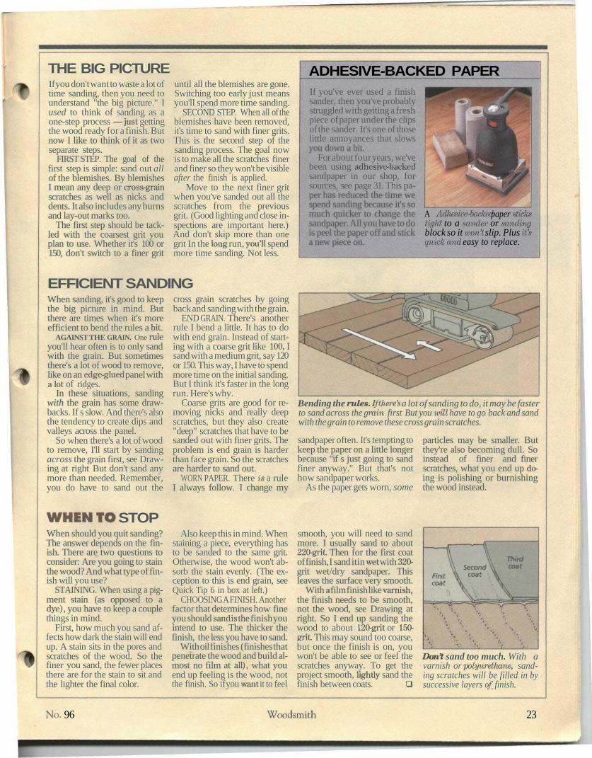
ADHESIVE-BACKED PAPERIf you've ever used a finishsander, then you've probablystruggled with getting a freshpiece of paper under the clipsof the sander. It's one of thoselittle annoyances that slowsyou down a bit.
For about four years, we'vebeen using adhesive-backedsandpaper in our shop, forsources, see page 31. This pa-per has reduced the time wespend sanding because it's somuch quicker to change thesandpaper. All you have to dois peel the paper off and sticka new piece on.
A Adfaesive-badced paper stickstight to a sander or sandingblock so it won't slip. Plus it'squick and easy to replace.
EFFICIENT SANDINGWhen sanding, it's good to keepthe big picture in mind. Butthere are times when it's moreefficient to bend the rules a bit
AGAINST THE GRAIN. One Rileyou'll hear often is to only sandwith the grain. But sometimesthere's a lot of wood to remove,like on an edge-glued panel witha lot of ridges.
In these situations, sandingwith the grain has some draw-backs. If s slow. And there's alsothe tendency to create dips andvalleys across the panel.
So when there's a lot of woodto remove, I'll start by sandingacross the grain first, see Draw-ing at right But don't sand anymore than needed. Remember,you do have to sand out the
cross grain scratches by goingback and sanding with the grain.
END GRAIN. There's anotherrule I bend a little. It has to dowith end grain. Instead of start-ing with a coarse grit like 100,1sand with a medium grit, say 120or 150. This way, I have to spendmore time on the initial sanding.But I think it's faster in the longrun. Here's why.
Coarse grits are good for re-moving nicks and really deepscratches, but they also create"deep" scratches that have to besanded out with finer grits. Theproblem is end grain is harderthan face grain. So the scratchesare harder to sand out.
WORN PAPER. There is a ruleI always follow. I change my
Bending the rules. If there's a lot of sanding to do, it may be fasterto sand across the grain first But you mil have to go back and sandwith the grain to remove these cross grain scratches.
sandpaper often. It's tempting tokeep the paper on a little longerbecause "if s just going to sandfiner anyway." But that's nothow sandpaper works.
As the paper gets worn, some
particles may be smaller. Butthey're also becoming dull. Soinstead of finer and finerscratches, what you end up do-ing is polishing or burnishingthe wood instead.
WHEN TO STOPWhen should you quit sanding?The answer depends on the fin-ish. There are two questions toconsider: Are you going to stainthe wood? And what type of fin-ish will you use?
STAINING. When using a pig-ment stain (as opposed to adye), you have to keep a couplethings in mind.
First, how much you sand af-fects how dark the stain will endup. A stain sits in the pores andscratches of the wood. So thefiner you sand, the fewer placesthere are for the stain to sit andthe lighter the final color.
Also keep this in mind. Whenstaining a piece, everything hasto be sanded to the same grit.Otherwise, the wood won't ab-sorb the stain evenly. (The ex-ception to this is end grain, seeQuick Tip 6 in box at left.)
CHOOSING A FINISH. Anotherfactor that determines how fineyou should sand is the finish youintend to use. The thicker thefinish, the less you have to sand.
With oil finishes (finishes thatpenetrate the wood and build al-most no film at all), what youend up feeling is the wood, notthe finish. So if you want it to feel
smooth, you will need to sandmore. I usually sand to about220-grit Then for the first coatof finish, I sand itin wet with 320-grit wet/dry sandpaper. Thisleaves the surface very smooth.
With a film finish like varnish,the finish needs to be smooth,not the wood, see Drawing atright. So I end up sanding thewood to about 120-grit or 150-grit. This may sound too coarse,but once the finish is on, youwon't be able to see or feel thescratches anyway. To get theproject smooth, lightly sand thefinish between coats. Q
Dont sand too much. With avarnish or polyurethane, sand-ing scratches will be filled in bysuccessive layers of finish.
No. 96 Woodsmith 23

S H O P P R O J E C T
Finishing CabinetThis cabinet does more than store your finishing supplies. It features a pull-out
tray, turntable top, and it can be rolled out of the way when not in use.
When it's time to apply a finish to a projectit seems like I have to hunt for an hour to
find all the things I need. My brushes hang in oneplace while the stain and varnish I'm looking forare stored somewhere else.
Then it's another challenge trying to find aclean place to set the project while applying thefinish. I thought about using my workbench. ButI'm usually working on another project making allkinds of dust. And unless I'm really careful, it's,pretty easy to spill varnish or stain all over the top.
So I decided it was time to organize my finish-ing "tools." That's what this Finishing Cabinet isdesigned to do. It stores all the supplies neededto finish a project in one handy location with room
on top to hold most projects.CABINET. All of my finishing supplies fit in this
cabinet that's basically a big wooden box onwheels. The doors and sides are built with peg-board panels that provide ventilation inside thecabinet. The panels are also a convenient place tohang brushes, masking tape, and other supplieson the outside.
Just above the doors is a slide-out tray. It pullsout from either side of the cabinet and holds yourfinishing supplies while you work.
TURNTABLE. Another useful feature we builtinto this project is the turntable top. This is espe-cially handy for small projects — you can sit inone place and still reach all sides of the project.
24 Woodsmith No. 96

EXPLODED VIEW
SIDE TRIM®
TOP RAIL (B)
FRONT/BACKTRIM TRAY
FRONT/BACKJ®
DOOR RAIL
@DOORSTILE
OVERALL DIMENSIONS:24"W x251/3"D x291/4"H
CASTER CLEATCaster
CUTTING DIAGRAM MATERIALS3/4" x T/4" x 96"
A
A
%" x 7'/4" x 96"
&
1/4" x r/4" x 96"G
N
3/4" x 3V2" x 48"s
(4.8 Bd. Ft)A j 0
1 0
(4.8 Bd. Ft)
B C P
C P
(4.8 Bd. Ft) I\ G / j , G :I N • v / / 7 y / / / / y /
(1.3 Bd. Ft) L v
I s t//|
0 'O
P '/////p V////
fi r-y/////////// 'f ;//;/// */'/////
H U
SUPPLIES(4) 11 /4"-dia. Wood Knobs(12) 7 / fe"-dia. Nylon Tack Glides(4pr.)2" Butt Hinges(16) #6 x V8" Fh Woodscrews(2) Magnetic Catches(8) Shelf Supports(4) 3" Swivel Casters with Brakes
• (16) 1 /4"-dia. x 1V;" Lag screws
• (18) #8 x 11/4" Fh Woodscrews• (6) #8 x 1 V2" Fh Woodscrews• (14) #8 x 2" Fh Woodscrews
Also Need:• One 4' x 8' sheet W plywood• One 4' x 4' sheet 1/4" pegboard• 3/4"- dia. Dowel
Stiles (4)Top Rails (2)Bottom Rails (2)Pegbd. Panels (2)Tray Support (1)Bottom (1)Face Trim (4)Tray Cleats (4)Bottom Cleats (2)Divider (1)Top(1)Trim Pieces (2)Tray Bottom (1)TrayFr./Bk.(2)Door Stiles (4)Door Rails (4)Door Panels (2)Shelves (2)Caster Cleats (2)Turntable (1)Side Trim (2)Fr./Bk.Trim(2)
W Pivot Pin (1)
3 / 4 X 3 - 2 5 V 4
3 / 4 X 5 - 1 7
3 / 4 X 3 - 1 71/4pegbd.- 17 x 173/43/4 p ly-21 x21V 2
3/4 ply-21 x21V2
3/4 X 13/4-21
3 / 4 X 1 -10Vs
3 / 4 X 1 - 21
3/4ply-211/2 x 19Vz3/4 p l y - 2 2 x 2 13 /4X3 /4 -22
3/4 ply-2015/i6x211/23/4X23/16-2015/16
3/4 x 3 - 223 / 4 X 3 - 1 71/4pegbd.- 17 x 161/23/4 ply - 91/2 x 207/s3 / 4 X 3 - 2 1
3/4 p ly-221/2X22V23/4X3 /4-221 /2
3/4 X 3/4 - 24
3/4-dia.dowel x 1 Vi
No. 96 Woodsmith 25

CABINETI started work on the finishing cabinet bymaking two identical side assemblies. Eachside assembly is made up of two stiles (ver-tical pieces), two rails (horizontal pieces),and a pegboard panel.
The key to holding these pieces togetheris a groove on the inside edge of the stilesand rails. This groove holds the panel inplace and forms a "mortise" for the tenonson the ends of the rails, see Fig. la.
Since the groove is the same size on allthe pieces (V4M wide x W deep), I startedby cutting all the stiles and rails (A, B,and C) to their finished width and length,see Fig. 1. Then I cut a centered groove onthe inside edge of all the pieces.
After the groove has been cut in the framepieces, the next step is to cut tenons on theends of the rails to fit the grooves in thestiles. With the tenons complete, the peg-board panels (D) can be cut to size. Thenthe entire side assembly can be glued andclamped together.
After the sides have been assembledthere's still two more things that need to bedone before they're complete. First, a rab-bet needs to be cut on the top inside face ofboth side assemblies, see Fig. Ib. The rab-bet is sized to accept a W plywood top that'sadded later, refer to Fig. 6.
Second, a dado is cut down the center ofboth side assemblies, see Figs. 1 and Ic. Adivider fits in this dado when the the cabinetis put together, refer to Fig. 4.
TRAY SUPPORT/BOTTOM. With the sidescomplete, I turned my attention to makingthe tray support (E) and bottom (F), seeFig. 2. They're made from 3/4M plywood andconnect the two side assemblies. Sincethey're the same size (21" wide x 21V2"long), I cut both at the same time.
NOTE: Finishedsize of Side Assembly
(25WHx 22W'W)
Insideface
Cut 1/4H x W stubtenon to fit VA" groove face
V Center dado onSide Assembly(See Detail c.)
Dado to matchthickness of3/4M plywood
But before the tray support and bottomare attached to the side assemblies, I addedface trim (G) to both pieces, see Fig. 2.These trim pieces are all cut to the samelength (21"), and hide the plywood edges onthe support and bottom. A tongue andgroove joint helps hold the trim in positionuntil the glue dries, see Fig. 2a.
CLEATS. Once the trim is attached, thenext step is to add cleats to the tray support(E) and bottom (F). These pieces of 3/4"stock are used to attach the tray support and
bottom to the side assemblies.However, since you need a W gap for the
divider, I used four tray cleats (H) on thetray support but only two cleats (I) on thebottom, refer to Figs. 2b and 4.
ASSEMBLY. After the cleats are glued inplace, the cabinet is ready to be assembled.To do this, first glue and screw the bottomto the side assemblies, see Fig. 3. Next,measure the distance between the dadoesin the side panels and cut the divider (J) tofit, see Fig. 4. (21VS" wide x 19W long.)
TRAY SUPPORT(3/4"x21* x21'/2')
dX
Use tongue and groove joint toattach Face Trim (See Detail a.)
NOTE:Lay Case
on side toattach Bottom
Bottom
Drill and countersinkpilot holes to fit #8 x 1
Fh Woodscrews
26 Woodsmith No. 96

Then slip the divider into the dadoes andglue and screw it to the bottom.
Now you can use the divider to help alignthe tray support in the cabinet To do this,set the tray support on the divider so thecleats glued on the bottom straddle the di-vider, see Fig. 4. Then align the bottom ofthe cleats with the bottom edge of the toprails and screw the tray support to the sideassemblies and divider, see Fig. 4a.
TOP. All that's left to complete the cabinetis to install a 3/4lf plywood top. To determinethe size, I first measured from shoulder toshoulder between the two rabbets on theside assemblies to get the width (22"). Thento find the length, I measured the width ofthe sides and subtracted 1W for trim piecesadded later. Now the top (K) can be cut tosize (22" wide x 21" long), see Fig. 5.
To finish the top, I glued on trim pieces(L) to the front and back edges, see Fig. 5.Then simply glue and screw the top to thecabinet, see Fig. 6.
TRAYWith the cabinet complete, the next step isto make a sliding tray. It fits between the top(K) and tray support (E). This tray pulls outfrom either side and holds your finishingsupplies while you use them.
TRAY. The tray is a piece of W-thick ply-wood with identical front and back pieces in-stalled on the ends. These front and backpieces have plastic glides mounted on topwhich help the tray slide easily in the cabi-net. And they keep it from sagging when it'spulled out
To determine the size of the tray bottom(M) start by measuring the width of theopening and subtract Vie" for clearance, seeFig. 7. (My tray bottom was 2015/16" wide.)
Finding the length of the tray bottom is abit trickier. That's because you need to takeinto account the joinery and the thicknessof the front and back pieces. So I measuredthe depth of the cabinet, subtracted 1", andcut the tray bottom to length (21V£"). Thento complete the tray bottom cut W tongueson two edges, see Fig. 7.
The next step is to cut the trayfront/back (N) pieces to size. The lengthof the pieces is the same as the width of thetray bottom (2015/l6"). But to determine theheight (width), first measure the opening inthe cabinet. Then subtract 5/V to allow forthe thickness of the glides (W) plus Vie" forclearance, see Fig. 7a. (In my case 23/l6".)
Now a V4M-wide groove can be cut on oneface of each piece to fit the tongues cut onthe tray bottom, see Fig. 7a.
After gluing the front and back pieces tothe bottom, I screwed a knob on both. Thento complete the tray, I added plastic glidesto the top edge of the front/back pieces, seeFigs. 7 and 7a.
NOTECleats areflush withbottomedge ofTop Rail
Install Topin rabbets on
Side Assemblies
NylonTack Glides
Use tongueand groove
joint to attachTray FrtJBk.TRAY
FRONT/BACK(23/ie" wide)
TRAY BOTTOM(3/4"x2015/i6"x211/2")
No. 96 Woodsmith 27
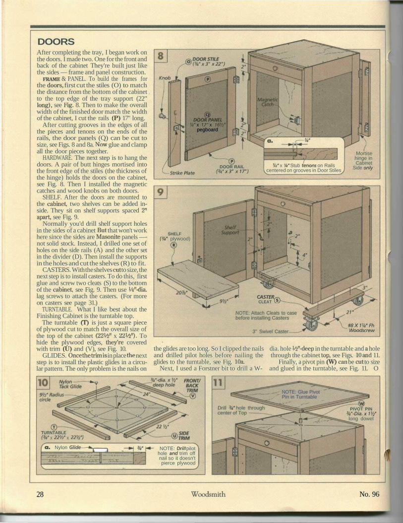
DOORSAfter completing the tray, I began work onthe doors. I made two. One for the front andback of the cabinet They're built just likethe sides — frame and panel construction.
FRAME & PANEL. To build the frames forthe doors, first cut the stiles (O) to matchthe distance from the bottom of the cabinetto the top edge of the tray support (22"long), see Fig. 8. Then to make the overallwidth of the finished door match the widthof the cabinet, I cut the rails (P) 17" long.
After cutting grooves in the edges of allthe pieces and tenons on the ends of therails, the door panels (Q) can be cut tosize, see Figs. 8 and 8a. Now glue and clampall the door pieces together.
HARDWARE. The next step is to hang thedoors. A pair of butt hinges mortised intothe front edge of the stiles (the thickness ofthe hinge) holds the doors on the cabinet,see Fig. 8. Then I installed the magneticcatches and wood knobs on both doors.
SHELF. After the doors are mounted tothe cabinet, two shelves can be added in-side. They sit on shelf supports spaced 2"apart, see Fig. 9.
Normally you'd drill shelf support holesin the sides of a cabinet But that won't workhere since the sides are Masonite panels —not solid stock. Instead, I drilled one set ofholes on the side rails (A) and the other setin the divider (D). Then install the supportsin the holes and cut the shelves (R) to fit.
CASTERS. With the shelves cut to size, thenext step is to install casters. To do this, firstglue and screw two cleats (S) to the bottomof the cabinet, see Fig. 9. Then use W-dia.lag screws to attach the casters. (For moreon casters see page 31.)
TURNTABLE. What I like best about theFinishing Cabinet is the turntable top.
The turntable (T) is just a square pieceof plywood cut to match the overall size ofthe top of the cabinet (22V<>" x 22 W. Tohide the plywood edges, they're coveredwith trim (U) and (V), see Fig. 10.
GLIDES. Once the trim is in place the nextstep is to install the plastic glides in a circu-lar pattern. The only problem is the nails on
QDOORPANEL
x 17" xpegboard
Mortisehinge inCabinet
Side onlyDOOR RAIL(3/4"x3" x17")
." x V4U Stub tenons on Railscentered on grooves in Door Stiles
SHELF(3/4u plywood)
CASTER^,CLEAT C5>--_
NOTE: Attach Cleats to casebefore installing Casters
#8X1V4"FhWoodscrew3" Swivel Caster
the glides are too long. So I clipped the nails dia. hole V^'-deep in the turntable and a holeand drilled pilot holes before nailing the through the cabinet top, see Figs. 10 and 11.glides to the turntable, see Fig. lOa. Finally, a pivot pin (W) can be cut to size
Next, I used a Forstner bit to drill a W- and glued in the turntable, see Fig. 11. O
NOTE: Glue PivotPin in Turntable
Drill 3/4" hole throughcenter of Top
PIVOT PIN3/4"-Dia.xV/2long dowel
TURNTABLE(3/4u x 221/2" x 221/2m)
Q. Nylon Glide NOTE: Drill pilothole and trim offnail so it doesn'tpierce plywood
28 Woodsmith No. 96

C O M M E N T S & Q U E S T I O N S
Talking ShopPAMPERING PINE• Some people think of pine asa "utility wood." You know,shelves in the garage, a table inthe laundry room, or saw horsesin the shop. But I also like tobuild furniture out of pine. Thatmeans "rethinking" the waythings get done in the shop.Let's face it, pine's a soft woodwith special requirements.
HANDLING
One requirement is that youhave to handle pine more care-fully than other woods. This canmake a big difference in howmuch work there will be when itcomes time to sand and finish it.
The problem is pine dentseasily — it doesn't take much toscratch and break the fibers. Soto make the shop "pine friendly,"I first give it a good cleaning. Iput away tools I'm not using andsweep off the bench. Chips anddried glue that I don't normallybother with get cleaned up.
Also, on a big project like theCountry Hutch, I'll use a sheetof plywood for a "furniture sled."
The project sits on the plywoodinstead of the concrete floor.That protects the ends of theboards from chipping out whensliding the project around.
But you can't avoid scratchesand dents completely. They'reinevitable — but not fatal. Mostscratches can be sanded outquickly. And most dents can beremoved too. I use a hot iron anda damp cloth. The dents soak upmoisture from the steam untilthey disappear.
TECHNIQUEJust as important as handlingpine is howyou work it The firstthing I do is make sure the tablesaw blade is sharp. A dull bladetears the soft fibers instead ofcutting them clean.
Also keep an eye on pitchbuildup on the saw blade. It cre-ates more resistance during thecut and the wood tends to burn.Note: An easy way to removepitch buildup is to soak yourblade in a common householdcleaner like Formula-409.
Drilling pine can also be a lit-tle tricky. When I used a newbrad point bit on the CountryHutch (refer to page 6) insteadof starting the hole cleanly, ittook chunks out of the wood. Ifound it helped to first run thehand drill in reverse. That waythe points on the bit scribe theoutside diameter of the hole slic-ing the wood fibers.
GLUING & SANDING
Just as the fibers in pine get tornwhen cutting and drilling, youcan also tear them out when re-moving dried glue — especiallyif you try to scrape it off.
So first I make sure not to usetoo much glue on the joints. Andany excess glue is cleaned upjust before it dries completely.Removing the excess now pre-vents tearing the fibers later.
SANDING. Sanding pine hasits own special challenges (seepage 22 for sanding tips). Nor-mally I'd use a finish sander tocomplete a project But on pineit leaves nearly invisible swirl
marks — until it's stained. So Ifinish sand my projects by hand.
It's also a good idea to use asanding block when sandingpine. Thaf s because it doesn'tsand evenly. Pine is made up ofboth soft and hard fibers (earlyand late wood). When you sandwithout a block, you removemore of the early wood becauseif s softer. What you end up withis a wavy surface instead of asmooth flat one.
FINISH
When finishing pine, there are acouple things to keep in mindthat will give you a better look-ing project.
First, pine doesn't absorbstain evenly so you get darkblotches on the wood. Try usinga stain controller (refer to page15). It evens out the amount ofstain that can soak into the pine.
Second, pid^iigrrterTwlurixrstains if possible. They don'thighlight missed dents, brokenfibers, or swirl marks as muchas dark colors. .
RIPPING CUPPED BOARDS• After reading the Shop Notessection of Issue 93, I have a
boards. I like to have the cupfacing up. But you show it be-ing ripped with the cup down.What's the best method forsafely ripping a cupped board?
Bruce DegarmoJanesville, Wisconsin
Actually, Bruce, I think bothmethods have advantages anddisadvantages.
CUP DOWN. Ripping with thecup down supports the work-piece on two edges. So it's stablefor most of the cat But the lastfew inches can cause problems.
As you complete the cut, thepiece between the fence and theblade can fall down and bind
against the blade. To reduce thepotential for kickback, 111 shovethe workpiece quickly throughthe last few inches of the cut(from behind, not on top).
CUP UP. The other method,ripping with the cup up, elimi-nates the binding and kickback
at the end of the cut By holdingthe board firmly agaist the tableand fence the pieces tend to fallaway from the blade.
But it seems like the board isless stable during the entire cut—not just the last few inches. Sothe chance for the board to bind
is greater (and so is the chancefor kickback).
HANDSAW. Probably the best(and safest) way to rip a cuppedboard and avoid kickback is notto use the table saw at all.
Instead, set up the band sawand rip the board to size.
CUPPED SIDE DOWN
To reduce chance of kickback,push workpiece auickly through
the last tew inches of the cut
NOTE: Always usea push stick
UP
Apply pressure hereto hold board tightagainst the fence
NOTE: Always usea push stick
No. 96 Woodsmith 29

R E A D E R ' S J I G
Circle Sanding JigThe circle sanding jig sent in byRon Hale of Joshua Tree, Cali-fornia works great. It allows youto accurately sand circularshapes on a disc sander.
The jig consists of two slidingtables. A base table that slidesside-to-side in the miter slot onthe disc sander. And a top tablethat holds the work piece andslides in-and-out
BASE. The base (A) is noth-ing more than a square piece ofplywood (6" x 6") with a groovein the top and bottom, see Fig.1. The groove in the top side is3/4"-wide and centered on thewidth of the piece. But thegroove in the bottom side is cutto match the width of the miter gauge slot.Note: Locate the bottom groove so the frontedge of base will end up Vi" away from thesanding disc, see detail in Fig. 2. Then cut arunner (B) to fit and glue it in place.
TOP. Attached to the top of base is an-other sliding table. The top table slides inand out and allows you to feed the work-piece into the spinning disc.
The top (C) is the same size as the base(A) and has a centered groove cut in the bot-tom side. This groove is the same size as theone you cut earlier in the top side of the baseand accepts a wood runner (D), see Fig. 1.
But before the runner is glued in place acouple of counterbored slots need to bedrilled in the top (C), see Fig.l. These slots
A This jig allows you to accurately sand a wide variety of differ-ent sized circles. And if you need several pieces the same size, thebuilt-in stop makes it easy.
FEATURE YOUR JIGIf you've built an original jigand would like to see it fea-tured on this page, send youridea to Woodsmith, Reader'sJig, 2200 Grand Avenue, DesMoines,IA 50312.
If we publish it, we'll sendyou $100 and a full set ofWoodsmith back issues, withbinders. (This set retails forover $300.) Include a sketch(or photo) of your jig and ex-plain how it's used. Andplease include a daytimephone number.
allow the top to be screwed to the base andstill slide in and out.
After gluing the runner (D) in place, a se-ries of five holes can be drilled in the top.These holes are drilled 1" apart and aresized to accept an axis pin (E). Dependingon which hole the pin is put in you can sandcircles from 2V£" to 10V&" in diameter.
ADJUSTABLE STOP. One of the unique fea-tures of this jig is the adjustable stop system.It makes it easy to sand several pieces to ex-actly the same size. (This is especiallyhandy if you're making toy wheels.)
Basically, the stop system consists of ablock (F), a piece of threaded rod, and aT-nut. The rod passes through a hole drilledin the block and threads into a T-nut in-
stalled on the back side, see Figs. 1 and 2.One end of the rod contacts the base and
stops the top from sliding closer to the disc.Attached to the other end is a wing and jamnut. When tightened together they form ahandle to make turning the rod easier. Asecond wing nut next to the block locks therod in place once the diameter is reached.
USING THE JIG. To use the jig, first draw acircle on your workpiece and rough cut it tosize. Next, drill a Vi" hole in the center andmount the workpiece on the axis pin.
Then with the rod touching the base,slowly back it out while rotating the work-piece against the disc until you reach thelayout line. Now to set the stop, simplytighten the wing nut against the block. Q
Rotate workpiece againstsanding disc until round74"- wide slot-
___ T«AXIS PIN
W-dia x 1" — Adjust screws soble slides smoothly
'/2n counterbore,deep -
TOP©3/4
plywood3/,6"x2V2"Threaded
Rod
Adjust bolt to setcircle diameter-
Cut groove %" NOTE: Space Axiswide x W deep Pin holes 1" apart
30 Woodsmith No. 96

m
COUNTRY HUTCHA complete hardware kit for theCountry Hutch, shown on page6, is available from WoodsmithProject Supplies. This kit in-cludes all the screws you'll need,plus the following hardware:• (8) Birch Shaker Knobs• (4 pr.) 2" x 1 W Butt Hinges• (4) Magnetic Catches• (16) Spoon-style Shelf Supports• (2) "Figure-8" Connectors• (2 pr.) 16" Full-extension
Drawer GlidesW96-796-100 CountryHutch Hardware Kit $49.95
Note: The same or similarhardware is available from someof the mail order sources thatare listed below.
NOTE BOARDThe Note Board on page 18 wasdesigned to hold a standard of-fice calendar (8W x 11"). Theonly hardware it requires is a fewwoodscrews. But if you wish todo the carving, you'll need thecarving tool listed below.
To carve the wheat pattern onthe top of the Note Board, Wood-smith Project Supplies is cur-rently offering a full-size pattern.W96-8005-650 Full-SizeWheat Carving Pattern $3.95
CARVING TOOL. To carve theaccent on the Note Board, wetried a number of tools. The onewe chose was a bent V-parting
WOODSMITH PRORDER BY MAIL
To order by mail, use the or-der form that comes with thecurrent issue. The order formincludes information on salestax as well as shipping andhandling charges.
If the mail order form is notavailable, please call our TollFree number at the right formore information on specificcharges and any applicablesales tax.
P R O J E C T
Souchisel. It's available from a number of sources, see below. Ouitool was made by Warren Tools(Item# PPTV-2). You can ordeia catalog with a price list fromthem directly by calling thenumber listed below.
FINISHESAll the projects in this issue werebuilt out of pine. Pine is hard tcstain. It soaks up the stain unevenly, leaving the surface of thewood looking blotchy.
Before staining pine, I usuallyprepare the wood with a coat olstain controller. It limits thepenetration of the stain, so thewood is colored more evenlyStain controllers are commonlyavailable, but they may be calledwood conditioners, dependingon the brand you choose.
STAINS. I used two differentbrands of stain For the CountryHutch, I used General FinishesHoney Maple Sealacell, see thesource listed below.
For the Note Board, I usedMinwax's Colonial Maple woodstain, available at many hard-ware stores and home centers.
TOPCOATS. I used the sametop coat for all the projects inthis issue: General Finishes'Royal Finish. It's available fromWoodsmith Project Suppliesand the source listed below.W96-4003-602 Royal Finish(Satin) $11.95 quart
[OJECT SUPPLIESORDER BY PHONE
For fastest service use our TollFree order line. Open Mondaythrough Friday, 7 AM to 7 PMCentral Time.
Before calling, please haveyour VISA, MasterCard, orDiscover Card ready.
1-800-444-7527
Note: Pnces subject tochange after February, 1995
S U P P L I E S
treesBiMicuiMfo CABINET special fabric on them already.
But if you have a sander with a> The Finishing Cabinet on page rubber or felt base, you'll need• 24 requires common hardware to add a conversion facing to the
that should be available at local pad on your sander.hardware stores or home cen- Note: Once you stick the fac-ters. Or you can order a kit from ing to the pad of your sander, it'sWoodsmith Project Supplies, pretty much on for good. ButThis kit includes everything you you can still use standard sand-will need except for the casters paper. Simply place the sandpa-(offered separately, see below) . per over the facing and clamp itThis kit includes all the screws in place as usual,as well as the following: Woodsmith Project Supplies• (4) 1W Wood Knobs is currently offering adhesive-• (12) Nylon Tack Glides backed sandpaper. It comes in• (4) 2" x 19/le11 Steel Hinges 4 V^'-wide rolls that are 10 yards• (2) Magnetic Catches long. The Conversion Facing is• (8) ShelfSupports 4 V^'x 11" but can be cut to size.• (16) V4" x 1V6" I,ag Screws W96-768-310 80 Grit $14.95W96-796-200 Finishing W96-768-320 100 Grit $14.95Cabinet Hardware Kit $12.95 W96-768-330 120 Grit $14.95
CASTERS. Woodsmith Project W96-768-340 180 Grit $14.95Supplies is also offering a set of W96-768-350 220 Grit $14.95four 3" locking casters for the W96-768-600 ConversionFinishing Cabinet These cast- Facing $3.95ers are general-duty swivel cast- cAuniMft Jir>ers with a load rating of 500 Ibs. «•»«•« SANDING JIGW96-796-250 Set of Four On page 30, we showed a jig that3"-dia. Locking Casters .. .$39.95 can be used to sand circles on a
_ disc sander. To build this jig,jJljp^fep you'll need some scrap pieces of
hardwood and plywood, plus theIn the sanding article on page 22 , following supplies:we mentioned the benefits of ad- • (1) #10-32 T-nuthesive-backed sandpaper. Cur- • (1) #10-32 Nutrently, there are several brands • (2) #10-32 Wing nutsavailable, see sources below. • (1) #10-32 x 3" Threaded Rod
The adhesive is designed to • (2) #8 x IVfc" Fh Woodscrewsbe attached to a special fabric. • (2) #10x1" Panhead ScrewsSome newer sanders have this • (1) Vi" x 1" Dowel
MAIL ORDER SOURCESSimilar hardware and supplies may be found in tha following
catalogs. Please call each company for a catalog or information.Cheny Tree Toys Constantines' Warren Tools
800-848-4363 800-223-8087 914̂ 876-7817Shaker Knotx AdJiesive-Backed Carving Tools
GarrettWade Sandpaper Wood Carvers Supply, Inc.800-221-2942 Highland Hardware 800-284-6229Adh&siw-Backed 800-241-6748 Carving ToolsSnMltw Adhesive-Backed The Woodcraft Shop
Woodcraft Sandpaper 800-397-2278800-22S-1153 The Woodworkers' Store Coming ToolsShaker Knobs, 800-279-4441Adiiesive-Backed. Hutch Hardware,Sandpaper Adhesive-Backed
Sandpaper, GeneralFinishes
No. 96 Woodsmith 31

A L A S T L O O K
Final DetailsCarved Note Board
A To give a decorative accent to our Note Board (see page 18), we addeda simple wheat carving. This requires just one inexpensive carving tool(and a utility knife). A step-by-step technique article begins on page 20.
Finishing Cabinet
A It seems a lot of "finishing" time is spent rounding up the supplies andfinding a clean surface to set the project on. This cabinet (page 24) keepseverything in one place. And the top rotates to make finishing easier.
Country Hutch
A Inexpensive phie lumber and straightforwardjoinery are combined to viake this classic CountryHutch. Complete step-by-step plans begin on page 6.
A Creating interesting details like these coves andrvund&vers on the Country Hutch is easy. All youneed is a router and a couple ofc&tnmon bits.
32 Woodsmith No. 96