Embed Size (px)
Citation preview
Issue 1.1 Page 1 of 13
Fol
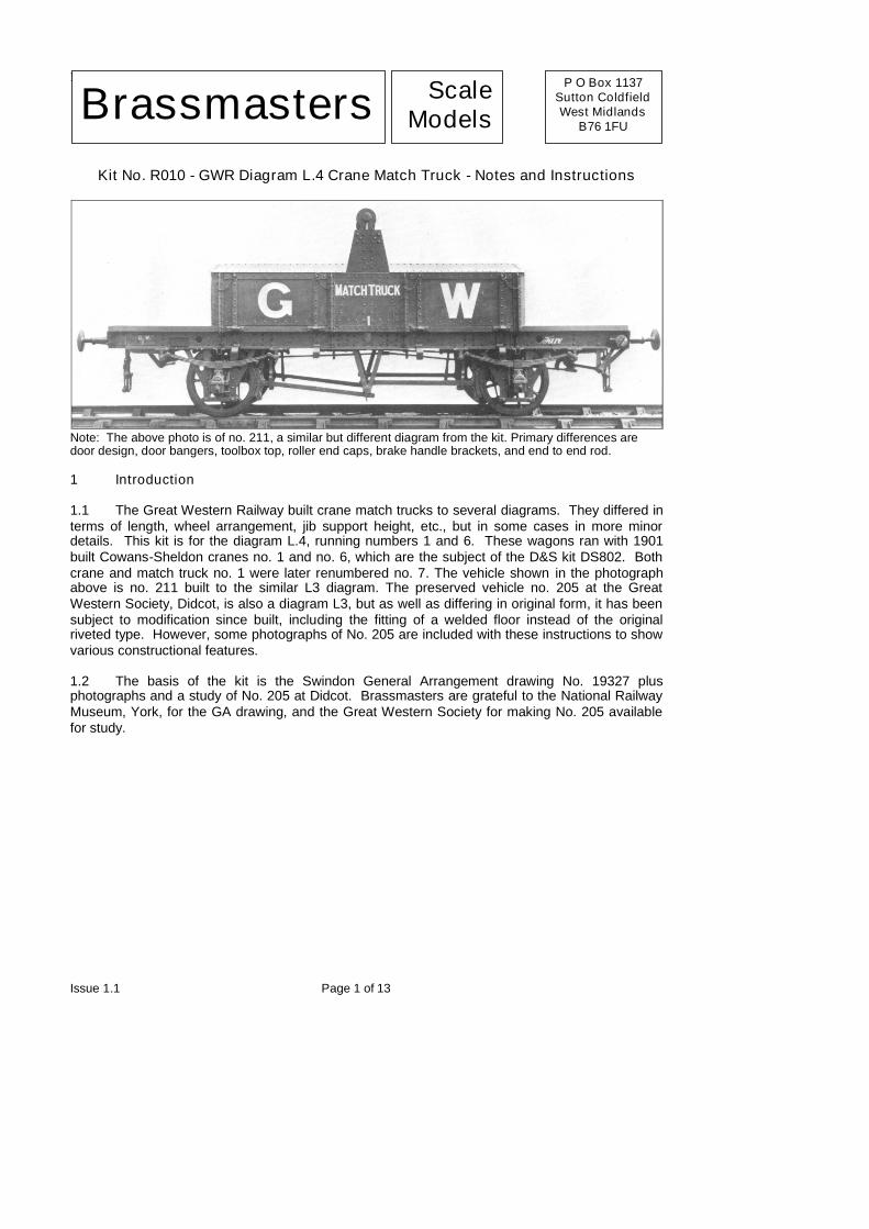
Kit No. R010 - GWR Diagram L.4 Crane Match Truck - Notes and Instructions
Note: The above photo is of no. 211, a similar but different diagram from the kit. Primary differences aredoor design, door bangers, toolbox top, roller end caps, brake handle brackets, and end to end rod.
1 Introduction
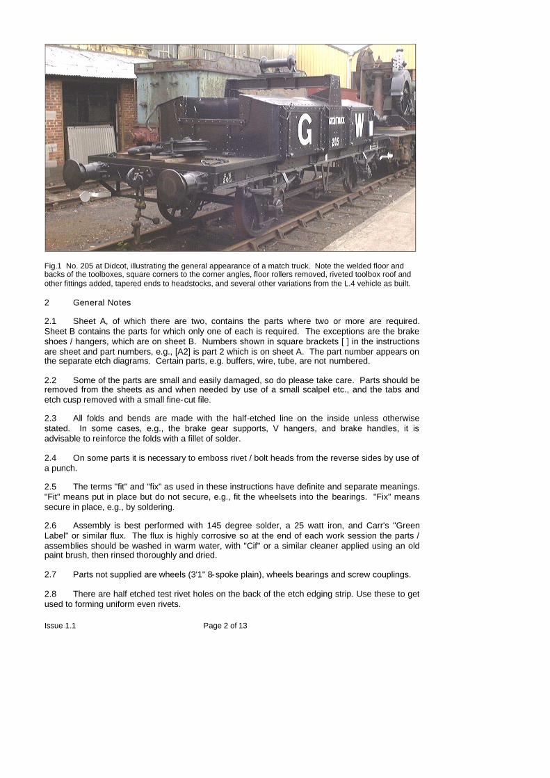
1.1 The Great Western Railway built crane match trucks to several diagrams. They differed interms of length, wheel arrangement, jib support height, etc., but in some cases in more minordetails. This kit is for the diagram L.4, running numbers 1 and 6. These wagons ran with 1901built Cowans-Sheldon cranes no. 1 and no. 6, which are the subject of the D&S kit DS802. Bothcrane and match truck no. 1 were later renumbered no. 7. The vehicle shown in the photographabove is no. 211 built to the similar L3 diagram. The preserved vehicle no. 205 at the GreatWestern Society, Didcot, is also a diagram L3, but as well as differing in original form, it has beensubject to modification since built, including the fitting of a welded floor instead of the originalriveted type. However, some photographs of No. 205 are included with these instructions to showvarious constructional features.
1.2 The basis of the kit is the Swindon General Arrangement drawing No. 19327 plusphotographs and a study of No. 205 at Didcot. Brassmasters are grateful to the National RailwayMuseum, York, for the GA drawing, and the Great Western Society for making No. 205 availablefor study.
Brassmasters ScaleModels
P O Box 1137Sutton ColdfieldWest Midlands
B76 1FU
Issue 1.1 Page 2 of 13
Fig.1 No. 205 at Didcot, illustrating the general appearance of a match truck. Note the welded floor andbacks of the toolboxes, square corners to the corner angles, floor rollers removed, riveted toolbox roof andother fittings added, tapered ends to headstocks, and several other variations from the L.4 vehicle as built.
2 General Notes
2.1 Sheet A, of which there are two, contains the parts where two or more are required.Sheet B contains the parts for which only one of each is required. The exceptions are the brakeshoes / hangers, which are on sheet B. Numbers shown in square brackets [ ] in the instructionsare sheet and part numbers, e.g., [A2] is part 2 which is on sheet A. The part number appears onthe separate etch diagrams. Certain parts, e.g. buffers, wire, tube, are not numbered.
2.2 Some of the parts are small and easily damaged, so do please take care. Parts should beremoved from the sheets as and when needed by use of a small scalpel etc., and the tabs andetch cusp removed with a small fine-cut file.
2.3 All folds and bends are made with the half-etched line on the inside unless otherwisestated. In some cases, e.g., the brake gear supports, V hangers, and brake handles, it isadvisable to reinforce the folds with a fillet of solder.
2.4 On some parts it is necessary to emboss rivet / bolt heads from the reverse sides by use ofa punch.
2.5 The terms "fit" and "fix" as used in these instructions have definite and separate meanings."Fit" means put in place but do not secure, e.g., fit the wheelsets into the bearings. "Fix" meanssecure in place, e.g., by soldering.
2.6 Assembly is best performed with 145 degree solder, a 25 watt iron, and Carr's "GreenLabel" or similar flux. The flux is highly corrosive so at the end of each work session the parts /assemblies should be washed in warm water, with "Cif" or a similar cleaner applied using an oldpaint brush, then rinsed thoroughly and dried.
2.7 Parts not supplied are wheels (3'1" 8-spoke plain), wheels bearings and screw couplings.
2.8 There are half etched test rivet holes on the back of the etch edging strip. Use these to getused to forming uniform even rivets.
Issue 1.1 Page 3 of 13
3 Basic Underframe
3.1 Emboss the rivets on the headstocks of the sub-floor [B1]. Drill the holes 0.5mm in therocking cradle pivots and 0.5mm in the V hangers, but to prevent damage to them, do not fold thisdetail down yet. Run a square file along the fold lines for headstock and headstock flange. Foldthe end flanges at 90 degrees to the headstocks, then the headstocks at 90 degrees to the floor.
3.2 File each solebar [A2] to the exact length and fix into the grooves on the underside of thesub-floor. Note the correct orientation: there is a small cut -out at each end of the solebar whichallows fixing under the flange of the headstock.
3.3 Fix each solebar bottom flange [A3] to the bottom of the solebar, between the end flanges.The bottom flange has a half-etched groove along one edge into which the solebar locates.
3.4 Emboss the rivets on the solebar overlays [A4] and fix each overlay to the solebars. Notethe correct orientation: towards each end there are two rivets set diagonally, the outer rivets mustbe towards the top of the wagon.
3.5 Fix the headstock overlays [A5] to the headstocks.
3.6 Bend down the rocking W iron supports in the floor assembly so they are at 90 degrees tothe floor.
3.7 Remove the brake handle brackets [B52, B53, B54] from the floor, but NOT the central Vhangers. Put them safely to one side!
3.8 Emboss the rivets on the floor [B6] then fix this to the sub-floor assembly, ensuring it isaccurately positioned. The four slots in the floor and sub-floor must be in alignment. Solder maybe applied around the edge of the floor and around the edges of the apertures in the sub-floor butdo ensure that it does not prevent the V hangers from being folded up later.
3.9 Tin the back of the roller brackets [A7] , fold in two and drill the holes 0.5mm. Fit a piece of0.5mm brass wire through the 1.0mm o/d tube 12.75mm long, and place a roller bracket on eachend. Check that the brackets fit through the holes in the floor. Trim the wire to length and fix thecompleted rollers to the six etched locations in the floor.
4 Toolboxes (two identical)
4.1 Tin the rear of the side door top straps [A16], hinge straps [A17], and floor corner strips[A18]. Remove them from within the toolbox frame [A8] and put them to one side for use later.
4.2 Care is required when bending the toolbox frame to ensure that it does not distort. Run asquare file along the two fold lines on each toolbox frame. For the top fold line the file needs to beangled each side of the horizontal as the finished fold is less than 90 degrees. The toolbox frameneeds to be held flat whilst bending. This can be achieved by holding one side of the bend flat witha steel rule whilst bending the other side up with a second rule. Alternatively, bending bars and arule can be used. Fold the frame so that the bottom is at 90 degrees to the back. Bend the frametop down to an angle less than 90 degrees, using the support [A9] as a guide. Fix the supports[A9] into the slots in the bottom by tipping them sideways and feeding them into the slots: ensurethat they are vertical Do not remove the excess length of the support tabs below the toolboxbottom - these are to locate the toolboxes on the floor.
4.2 Emboss the rivets on the toolbox back overlay [A10] then fix it to the frame with thehorizontal riveted strapping at the bottom. Solder may be applied from within through the aperturesin the frame as well as around the edge.
Issue 1.1 Page 4 of 13
4.3 Emboss the rivets on the I-beam support inner layer [A11]. Remove the I-beam top gusset[A39] from within the I-beam support outer layer [A12] and put to one side. Fix the I-beam innerlayer [A11] and I-beam outer layer [A12] together back-to-back and fix this assembly to therecesses in the centre front of the toolbox frame, ensuring that it is flush with the front of thetoolbox frame.
4.4 Emboss the rivets on the toolbox top overlay [A13] then fix it to the frame. Take care toensure that the top has an equal overhang at each end, and no overhang at the back.
4.5 The completed model without any additional weight will weigh 32 gram’s or 1 1/8th oz.Additional weight, if required, may be added to the model in several positions including under thefloor and within the toolboxes. If weight is to be added within the toolboxes it should be done atthis stage.
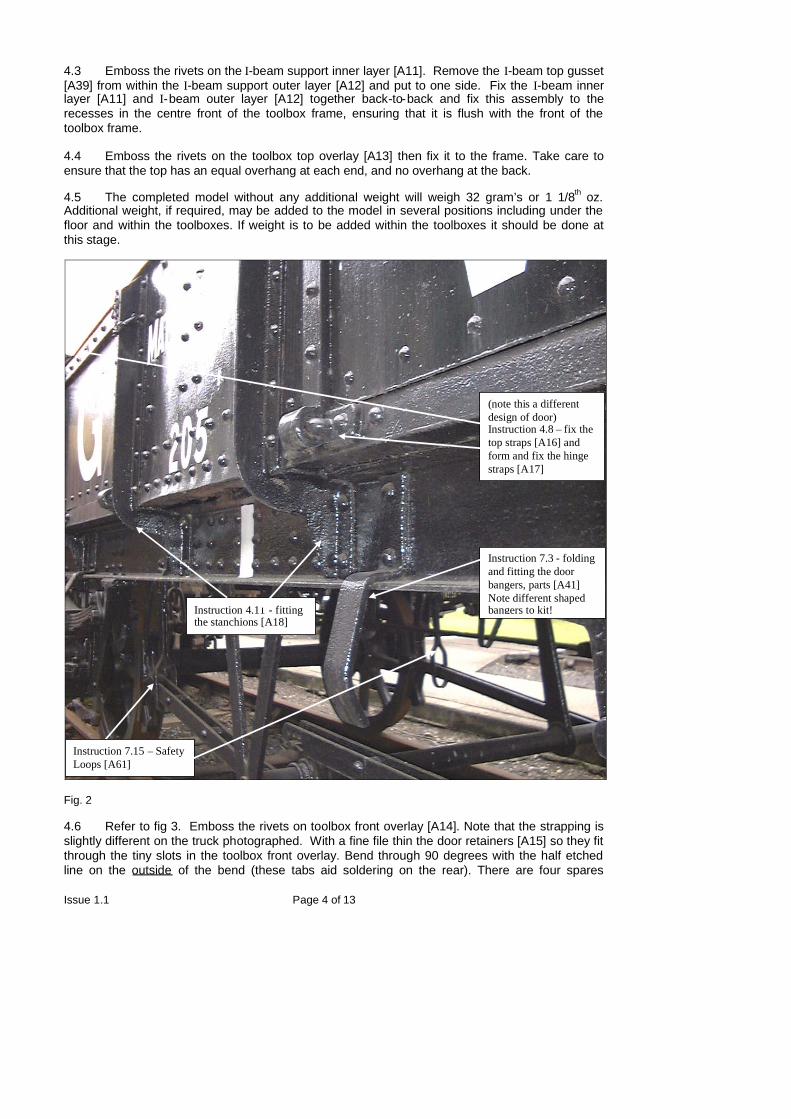
Fig. 2
4.6 Refer to fig 3. Emboss the rivets on toolbox front overlay [A14]. Note that the strapping isslightly different on the truck photographed. With a fine file thin the door retainers [A15] so they fitthrough the tiny slots in the toolbox front overlay. Bend through 90 degrees with the half etchedline on the outside of the bend (these tabs aid soldering on the rear). There are four spares
(note this a differentdesign of door)Instruction 4.8 – fix thetop straps [A16] andform and fix the hingestraps [A17]
Instruction 7.3 - foldingand fitting the doorbangers, parts [A41]Note different shapedbangers to kit!Instruction 4.11 - fitting
the stanchions [A18]
Instruction 7.15 – SafetyLoops [A61]
Issue 1.1 Page 5 of 13
included so do not spend too much time looking for the one you dropped! Insert through overlayfrom the rear with the 90 degree return towards the bottom of the door. Fix in place.
4.7 Using the half etched line lines on the bottom of the toolbox frame to align with the slots forthe stanchions in the toolbox front, tack the toolbox front in position. Carefully wrap the ends roundthe end of the toolbox frame. Unsolder the overlay from the toolbox frame and complete the bendsusing a 2.0mm drill as a former. When satisfied that the overlay is a good fit on the toolbox frame,fix it to the toolbox frame. Use the minimum amount of solder and clean off any excess using afibreglass brush.
4.8 Fix the door top horizontal straps [A16] (previously removed from within [A8]) in place onthe doors. Fix the door hinge straps [A17] (also previously removed from within [A8]) to the doorhinges, with the rivets towards the top.
4.9 The next bit is fiddly! Eight hinges are required now for the side doors and another fourlater for the end doors. From experience it is best to manufacture these in a batch to ensureuniformity. Each is formed by cutting a 0.85mm piece of 0.8mm o/d tube and a 1.6mm piece of0.5mm wire. Making two simple jigs is the easiest way to ensure uniform length. Using a piece ofscrap paxolin (e.g. copper-clad sleeper), file to 0.85mm thick at one end and drill a hole 0.8mm sothe tube is a tight fit. Then simply push the tube through the sleeper, align flush at the rear and cutit off level with the front using a fine saw. A similar jig 1.6mm thick drilled for the 0.5mm wireensures these too are uniform length. Fix the wire centrally through the hole in the tube. Fix theassembly at the bottom of the hinge strap to represent the hinge Repeat for the other 11 doorhinges, putting 4 to one side for the end doors.
4.10 Fix each toolbox in place on the floor, locating the tabs in the slots.
4.11 Curve the floor corner strips [A18] (previously removed from within the toolbox frames)and fix in the half-etched slots in the floor, with their ends abutting the toolboxes. Fix thestanchions [A19] to the toolboxes / solebars, as shown in fig. 2. Be careful not to apply too muchpressure when fitting as the toolbox sides may distort!
5 Cross Member and End Doors
5.1 Referring to fig. 3, emboss the rivets on each of the two layers of the toolbox cross member[A20], and fix them back to back. Fix in place in the slots in the centre of the back of the twotoolboxes.
5.2 Emboss the rivets on each end door [A21] - note there are rivets to be embossed from bothsides. Fix the hinge / strapping detail [A22] to the outer side. Take the four hinges constructedpreviously (see 4.9) fix them at the bottom of the hinge strap to represent the hinge. Trim the doorretainers [A15] and fit through from the rear. File the rear flush and fix in place. Fix the U-angle[A23] to the inner side of each door. Fix the doors in place between the ends of the toolboxes.
Issue 1.1 Page 6 of 13
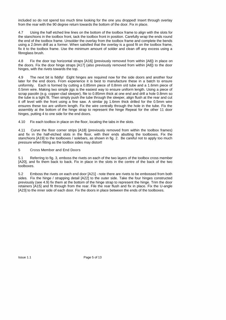
Fig. 3
6 Jib Support
6.1 Referring to fig. 3, emboss the rivets on the four triangular web pieces, two [A24] and two[A25]. Fix the pieces together "back to back" to produce two webs, then fix these to the toolboxtops / I-beam supports.
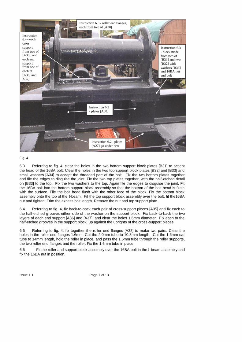
6.2 Emboss the rivets on the two layers of the I-beam vertical plate [A26] and fix the layerstogether back-to-back. Referring to fig. 4, fix the plates [A27] to the I-beam lower flange [B28],and then fix this and the upper flange [B29] to the vertical. Fix in place the four small verticalplates [A30].
Instruction 6.1 -triangular webfrom one of eachof parts [A24]and [A25]
Instruction 5.1 - crossmember from two parts [A20]
Instruction 6.7 - gusset plate [A39]
Issue 1.1 Page 7 of 13
Fig. 4
6.3 Referring to fig. 4, clear the holes in the two bottom support block plates [B31] to acceptthe head of the 16BA bolt. Clear the holes in the two top support block plates [B32] and [B33] andsmall washers [A34] to accept the threaded part of the bolt. Fix the two bottom plates togetherand file the edges to disguise the joint. Fix the two top plates together, with the half-etched detailon [B33] to the top. Fix the two washers to the top. Again file the edges to disguise the joint. Fitthe 16BA bolt into the bottom support block assembly so that the bottom of the bolt head is flushwith the surface. File the bolt head flush with the other face of the block. Fix the bottom blockassembly onto the top of the I-beam. Fit the top support block assembly over the bolt, fit the16BAnut and tighten. Trim the excess bolt length. Remove the nut and top support plate.
6.4 Referring to fig. 4, fix back-to-back each pair of cross-support pieces [A35] and fix each tothe half-etched grooves either side of the washer on the support block. Fix back-to-back the twolayers of each end support [A36] and [A37], and clear the holes 1.6mm diameter. Fix each to thehalf-etched grooves in the support block, up against the uprights of the cross-support pieces.
6.5 Referring to fig. 4, fix together the roller end flanges [A38] to make two pairs. Clear theholes in the roller end flanges 1.6mm. Cut the 2.0mm tube to 10.8mm length. Cut the 1.6mm o/dtube to 14mm length, hold the roller in place, and pass the 1.6mm tube through the roller supports,the two roller end flanges and the roller. Fix the 1.6mm tube in place.
6.6 Fit the roller and support block assembly over the 16BA bolt in the I-beam assembly andfix the 16BA nut in position.
Instruction 6.2 - plates[A27] go under here
Instruction 6.3- block madefrom two of[B31] and two[B32] withwashers [B33]and 16BA nutand bolt
Instruction6.4 - eachcrosssupportfrom two of[A35], andeach endsupportfrom one ofeach of[A36] andA37]
Instruction 6.2- plates [A30]
Instruction 6.5 - roller end flanges,each from two of [A38]
Issue 1.1 Page 8 of 13
6.7 Fix the I-beam assembly between the supports on the toolboxes. Referring to fig. 3, fix thegusset plates [A39] (previously removed from within [A13] and stored safely!) to the ends of thetop of the I-beam.
7 Underframe Detail
7.1 The following steps are best performed with the model inverted and supported at the endson blocks, so as not to damage the jib support.
7.2. Fold up and fix in place the spring bump stops [A40] to the half-etched locations on theunderside of the solebars.
7.3 Emboss the rivets on the door bangs [A41] then, referring to fig. 2, fold up and fix them inplace on the solebars in line with the door hinge straps. Note that the door bangs are not formedinto a curved shape, but as per fig. 5. All bends, including the one at the extreme end should be at90 degrees with the half etched line on the inside.
7.4 Emboss the rivets on the retaining straps on the W-iron units [B42 and B43]. Also embossa bolt head ‘rivet’ on the top of each brake block to represent the bolt where it attached to thebrake hanger. Fold the straps over 180 degrees - half etched line to the outside of the fold. Openout the bearing holes to accept the bearings, and fix the bearings in place. Fix a brake shoe inner[B44] to each brake hanger / shoe, ensuring that they are on the inside. Drill the hole in the shoe /hanger 0.35mm. Note that the shoes are of the post-1911 ‘double-ended’ type - for the originaltype of shoe, file off the lower hanger lug. Fold the unit at right angles at the half etched lines.Note that there is an error in the last short section of the half etched grooves, so that the unit willnot sit in it. File back the edge of the last short section of the unit that sits on the floor, so that theunit fits squarely to the floor. Fix each unit in place.(For 00 gauge, break the brake hanger and shoe off from the rest of the W-iron unit at the last
bend line and fix in position in line with wheel tread.
7.5 Emboss the rivets on the retaining straps of the rocking cradle W-iron unit [B45]. Fold thestraps over 180 degrees - half etched line to the outside of the fold. Drill the pivot holes 0.5mm.Open out the bearing holes to accept the bearings and fix the bearings in place. Fix a brake shoeinner [B44] to each shoe / hanger [B46 and B47] ensuring that you make one right-hand and oneleft-hand. Drill the hole in the shoe / hanger 0.35mm and form a bolt head ‘rivet’ on the top of eachbrake block to represent the bolt, by riveting from behind through the top ‘lug’ hole or the innershoe. Again, remove the lower lug on each shoe for the pre-1911 type. Fix these assemblies inthe outer slots in the cradle.(For 00 gauge, use the inner slots.)
7.6 Fit the cradle between the supports in the floor and pass a length of 0.5mm wire throughthe holes. Ensure the cradle is free to rock. Do not fix the wire in position.
7.7 Fit the chosen wheelsets (which should be 8 spoke, 3’ 1” diameter) and check and adjustthe position of the brake shoes.
7.8 Bend down the V hangers on the sub-floor. Cut a piece of 0.8mm tube 23.5mm long toform the brake shaft to fit between the V hangers. Drill each end of the tube 0.6mm for a shortdistance and fit a short length of 0.6mm wire. Trim and file square so that it will just protrudethrough the V hanger. Fix a double-ended crank [A48] and a half etched double ended crank [A49]together. Drill 0.8mm in the centre and 0.35mm in the two outer holes. Repeat for the other pair ofdouble-ended cranks. Drill the single lever [B50] 0.8mm at the larger end and 0.35mm at the otherend. Slide the double-ended crank and the lever onto the brake shaft. Fit the brake shaft betweenthe V hangers. Fix the double-ended cranks in position in line with the brake blocks.
7.9 On the prototype the 8 brake push rods were fitted in pairs with a gap between. They wereheld apart by spacers in the middle (packing pieces may have been used later) and boltedtogether (refer to Fig 3, which has 2 spacers!). No spacers were required at the ends as at one
Issue 1.1 Page 9 of 13
end the rods were either side of the brake block, and at the other end they were either side of thedouble ended crank.
Drill the single holes in the brake push rods [B51] 0.35mm and also drill the centre hole in the rowof three in the seven hole end 0.35mm. Fix short pieces of 0.3mm wire to the centre, brake blockand V hanger holes of one push rod, so they protrude 3mm at 90 degrees from these holes, this iseasy to do if the wire is trimmed after fixing. Test fit in position between the brake blocks and thedouble ended cranks. Remove and using a piece of scrap etch to “space” the second brake pushrod out the same thickness as the brake shoe, solder the centre piece of wire in place. Carefullyspring the ends in place around the brake block and around the double ended crank taking carenot to bend the push rod. For the non-rocking wheelset end solder in place, the rocking end shouldbe left free to move allowing the W iron to rock.
7.10 Drill the holes in the inner brake handle brackets [B52 and B53] and outer brake handlebrackets [B54] 0.6mm. Fold the feet to 90 degrees. Fix the inner bracket to the half etched locationat each end of the sub-floor, with the feet facing towards the centreline of the wagon. Align theinner bracket and fix the other foot to the headstock flange. Pass a piece of 0.6mm wire throughthe inner bracket and the outer bracket, and locate the outer bracket on the solebar flange with thefeet facing towards the centre line of the wagon. Align the wire parallel with the headstock and fixthe outer bracket in position on the solebar flange. Repeat for the other end. Note: one end hasthe inner bracket a lot closer to the outer bracket than the other end.
7.11 Starting with the end that has the longer distance between the two brackets, drill the holesin the ratchet quadrant [B55] the release cam [B56] and the end-to-end link [B57] 0.6mm. Cut apiece of 0.6mm wire 23mm long. Referring to fig. 6, thread the ratchet quadrant and release camonto the wire. Feed the wire in the inner and outer brake handle brackets and fix in position.Position the ratchet quadrant and the release cam and fix in position. Position the end-to-end leveron the inner end of the wire outboard of the inner bracket and fix in position.
7.12 For the opposite end of the wagon, drill the end-to-end link [B58] 0.6mm. Cut a piece of0.6mm wire 9mm long. Referring to fig. 7, thread the end-to-end lever onto the wire. Feed the wirein the inner and outer brake handle brackets and fix in position. Position the end-to-end lever andfix into position.
7.13 Angle the lever located on the brake shaft in the position shown in fig. 8 and fix in position.Cut a piece of 0.33mm wire to length to reach from the lower part of the ratchet quadrant to the topend of the lever and fix in position at both ends. Cut a piece of 0.33mm wire 79mm to reachbetween the two end-to-end levers on the two brake handle shafts and fix in position at both ends.Take the end-to-end rod support [B59] and fix two 2mm pieces of 0.33mm wire to the two holes torepresent the ‘bobbins’ that supported the end-to-end rod. Fix in position centrally on the sub floor,with the bobbins facing outwards. Fix the end-to-end rod to the support.
7.14 Drill the brake handles [A60] 0.6mm. Bend to shape and fix in position on the outer ends ofthe two brake handle shafts.
7.15 The safety loops [A61] have to be formed as shown in fig 2. This is the last fiddly bit! Startwith the fixed W Iron end. It is easiest to break the loop into two pieces at the bend that will bebottom towards the centre of the truck, thereby forming a front and rear half. Form these and trimthe length so they sit correctly just below the brake push rods. Strengthen the bends with solder.Fit and then fix the front half around the push rods soldering to the brake hanger extensionsupports. Repeat with the rear half. Repeat for the other three loops but ensure the brake rodsare free to move at the rocking W iron end.
7.16 Fix the cast axlebox and springs onto the W-irons. Ensure the cradle is free to rock, a slight‘flattening’ of the spring will help. Fix the wire holding the rocking W iron cradle into position.
7.17 Fit the buffers in place. Fit the couplings of your choice (the prototype had screwcouplings).
Issue 1.1 Page 10 of 13
7.18 Two styles of numberplate are provided, [A62] two-bolt and [A63] four bolt fixing. Both havepush through rivets to represent the bolt heads. Select whichever is appropriate to your model.These may be fixed to the solebar now, or if you prefer, after they have been painted and lettered.Positions varied so refer to a photograph.
8 Finishing
8.1 Paint the model all over black and add transfers (including on the number plates) thenvarnish as appropriate.
8.2 Admire your completed model and think about building the D&S crane! Study photographsof the crane as Brassmasters produce a detailing kit that includes a cab roof and replacementcrane frame plates.
9 References
GWR Goods Wagons – Atkins Beard Tourret, TP, Chapter 15
Great Western Wagons Appendix – Russell, OPC, Fig. 310 (note caption for Fig.309 and Fig.310are transposed)
Great Western Steam Through the Years – Bradford Barton, Page 32
Swindon GA Drawing 19327 – National Railway Museum

Issue 1.1 Page 11 of 13
Fig. 5 Crane Match Truck No 7 Diagram L4 at Old Oak Common in the early part of the 20 th century.
Fig. 6 Fig. 7
Fig. 8
Deleted: <sp>

Issue 1.1 Page 12 of 13
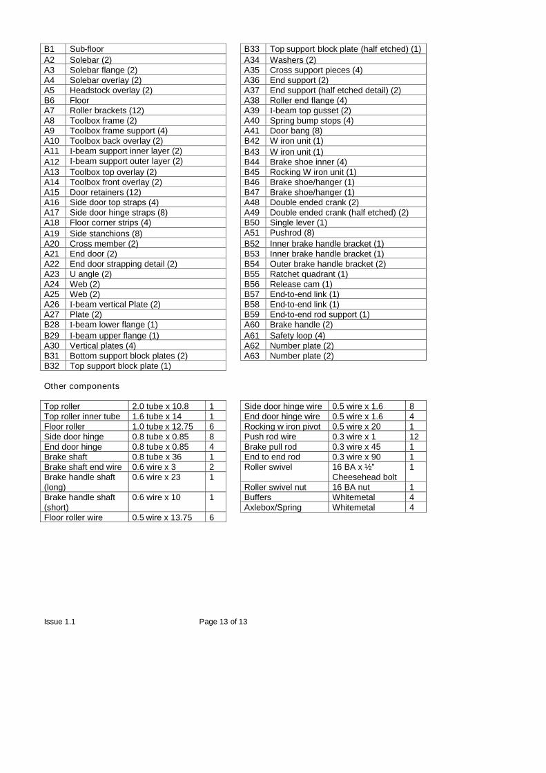
Component List
Etches
Sheet A – 2 off Sheet B – 1 off
Issue 1.1 Page 13 of 13
B1 Sub-floorA2 Solebar (2)A3 Solebar flange (2)A4 Solebar overlay (2)A5 Headstock overlay (2)B6 FloorA7 Roller brackets (12)A8 Toolbox frame (2)A9 Toolbox frame support (4)A10 Toolbox back overlay (2)A11 I-beam support inner layer (2)A12 I-beam support outer layer (2)A13 Toolbox top overlay (2)A14 Toolbox front overlay (2)A15 Door retainers (12)A16 Side door top straps (4)A17 Side door hinge straps (8)A18 Floor corner strips (4)A19 Side stanchions (8)A20 Cross member (2)A21 End door (2)A22 End door strapping detail (2)A23 U angle (2)A24 Web (2)A25 Web (2)A26 I-beam vertical Plate (2)A27 Plate (2)B28 I-beam lower flange (1)B29 I-beam upper flange (1)A30 Vertical plates (4)B31 Bottom support block plates (2)B32 Top support block plate (1)
B33 Top support block plate (half etched) (1)A34 Washers (2)A35 Cross support pieces (4)A36 End support (2)A37 End support (half etched detail) (2)A38 Roller end flange (4)A39 I-beam top gusset (2)A40 Spring bump stops (4)A41 Door bang (8)B42 W iron unit (1)B43 W iron unit (1)B44 Brake shoe inner (4)B45 Rocking W iron unit (1)B46 Brake shoe/hanger (1)B47 Brake shoe/hanger (1)A48 Double ended crank (2)A49 Double ended crank (half etched) (2)B50 Single lever (1)A51 Pushrod (8)B52 Inner brake handle bracket (1)B53 Inner brake handle bracket (1)B54 Outer brake handle bracket (2)B55 Ratchet quadrant (1)B56 Release cam (1)B57 End-to-end link (1)B58 End-to-end link (1)B59 End-to-end rod support (1)A60 Brake handle (2)A61 Safety loop (4)A62 Number plate (2)A63 Number plate (2)
Other components
Top roller 2.0 tube x 10.8 1Top roller inner tube 1.6 tube x 14 1Floor roller 1.0 tube x 12.75 6Side door hinge 0.8 tube x 0.85 8End door hinge 0.8 tube x 0.85 4Brake shaft 0.8 tube x 36 1Brake shaft end wire 0.6 wire x 3 2Brake handle shaft(long)
0.6 wire x 23 1
Brake handle shaft(short)
0.6 wire x 10 1
Floor roller wire 0.5 wire x 13.75 6
Side door hinge wire 0.5 wire x 1.6 8End door hinge wire 0.5 wire x 1.6 4Rocking w iron pivot 0.5 wire x 20 1Push rod wire 0.3 wire x 1 12Brake pull rod 0.3 wire x 45 1End to end rod 0.3 wire x 90 1Roller swivel 16 BA x ½”
Cheesehead bolt1
Roller swivel nut 16 BA nut 1Buffers Whitemetal 4Axlebox/Spring Whitemetal 4