Embed Size (px)
Citation preview
-1--1-
FOIL GAS BEARING SUPPORTEDHIGH SPEED BLOWERS
11th Annual SECA WorkshopPittsburgh, PA
Sponsor: Department of Energy
Presented by: Dr. Giri Agrawal (Principal Investigator) R&D Dynamics Corporation
Date: July 29, 2010
-2--2-
Outline
1. R&D Dynamics Overview Update
2. Foil Gas Bearing Supported Cathode/Anode Recycle Blowers for Large Megawatt Size SOFC Power Plants
3. Low Cost Cathode Blower
-3--3-
1. R&D DYNAMICS OVERVIEW UPDATE

-4--4-
Design, Develop and Production Manufacture Oil-Free, Efficient, and Affordable High-Speed Turbomachinery
OUR BUSINESS
-5--5-
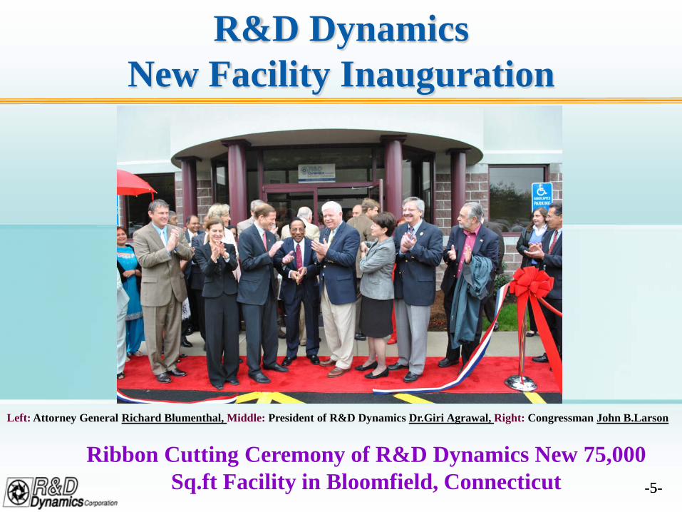
R&D Dynamics New Facility Inauguration
Left: Attorney General Richard Blumenthal, Middle: President of R&D Dynamics Dr.Giri Agrawal, Right: Congressman John B.Larson
Ribbon Cutting Ceremony of R&D Dynamics New 75,000 Sq.ft Facility in Bloomfield, Connecticut
-6--6-
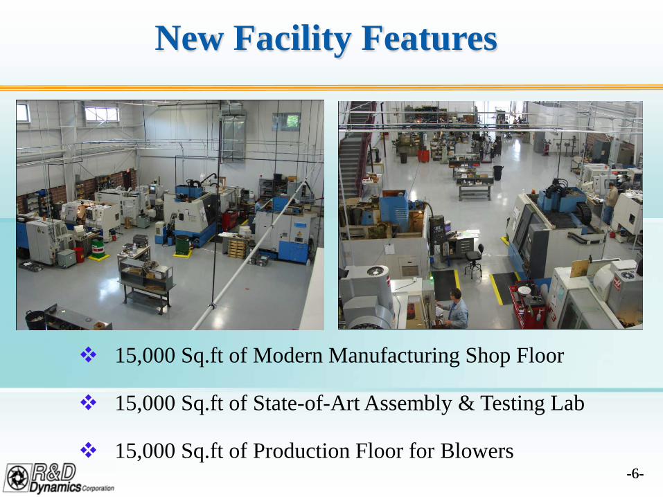
New Facility Features
15,000 Sq.ft of Modern Manufacturing Shop Floor
15,000 Sq.ft of State-of-Art Assembly & Testing Lab
15,000 Sq.ft of Production Floor for Blowers
-7--7-
Fuel Cell Blowers Update
R&D Dynamics is entering into supply agreements for 1,000 units
of blowers per year.
The new 75,000 Sq.ft facility will allow the set up of production
line.
Recent testing of Low Cost Blower developed using DFMA
techniques has proved viability of cost effective blower solution
for fuel cell applications.
-8--8-
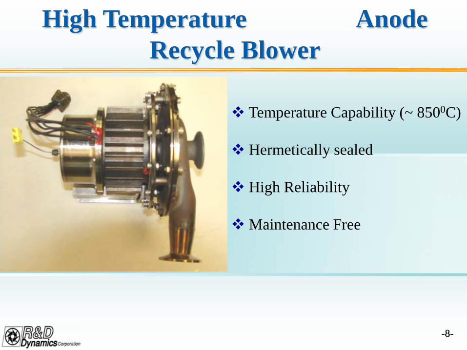
High Temperature Anode Recycle Blower
Temperature Capability (~ 8500C)
Hermetically sealed
High Reliability
Maintenance Free
-9--9-
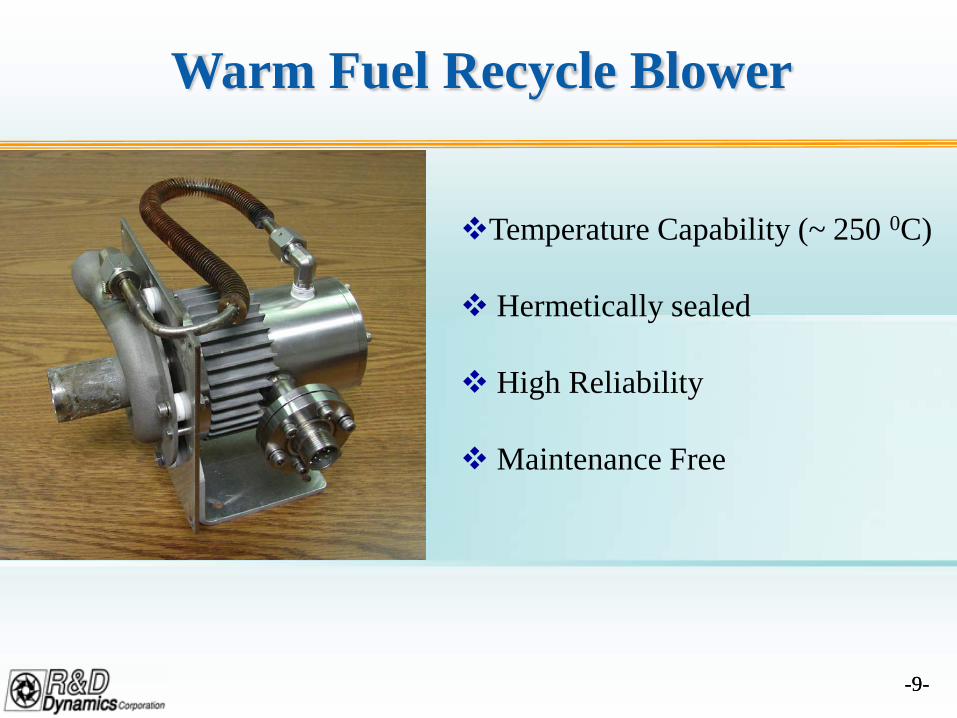
Warm Fuel Recycle Blower
Temperature Capability (~ 250 0C)
Hermetically sealed
High Reliability
Maintenance Free
-10--10-
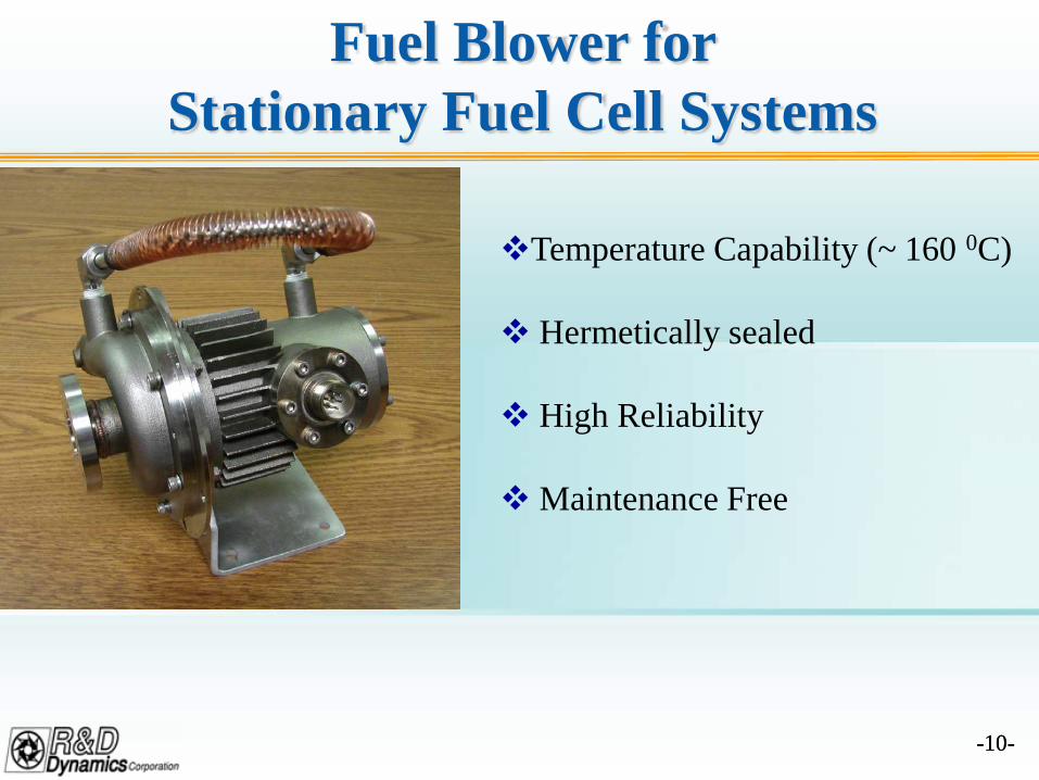
Fuel Blower for Stationary Fuel Cell Systems
Temperature Capability (~ 160 0C)
Hermetically sealed
High Reliability
Maintenance Free
-11--11-
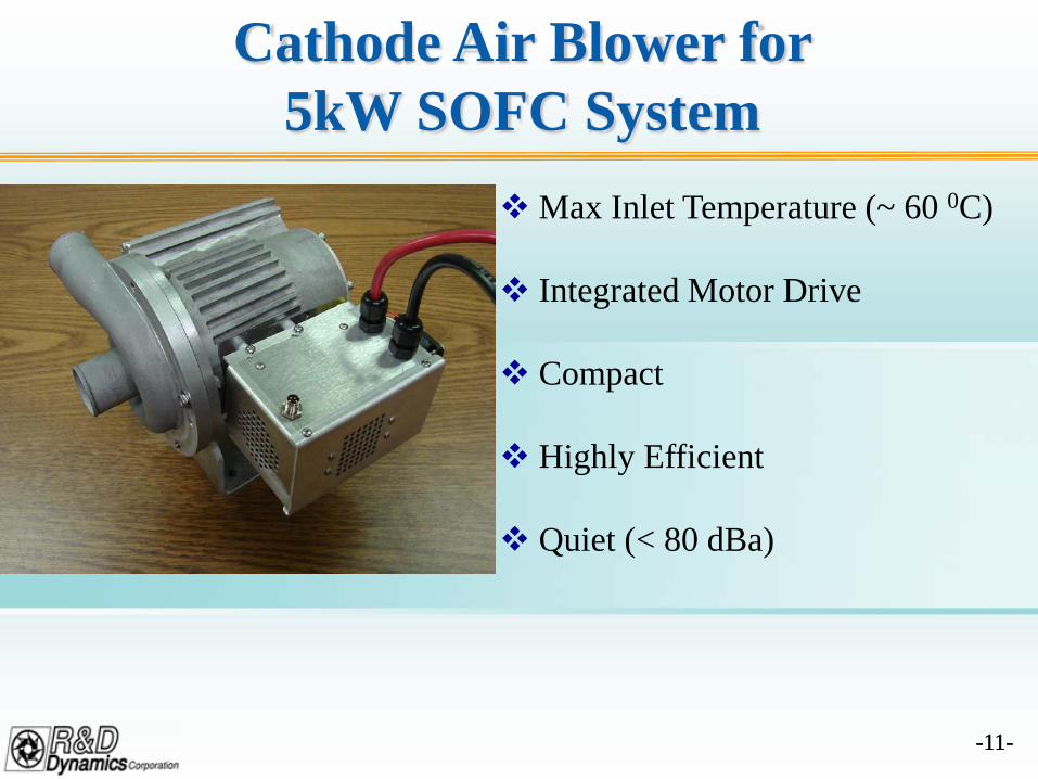
Cathode Air Blower for 5kW SOFC System
Max Inlet Temperature (~ 60 0C)
Integrated Motor Drive
Compact
Highly Efficient
Quiet (< 80 dBa)
-12--12-
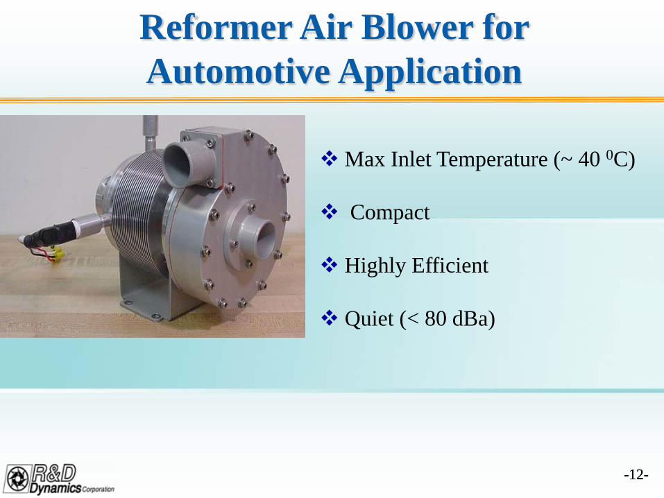
Reformer Air Blower for Automotive Application
Max Inlet Temperature (~ 40 0C)
Compact
Highly Efficient
Quiet (< 80 dBa)
-13--13-
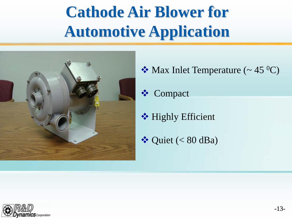
Cathode Air Blower for Automotive Application
Max Inlet Temperature (~ 45 0C)
Compact
Highly Efficient
Quiet (< 80 dBa)
-14--14-
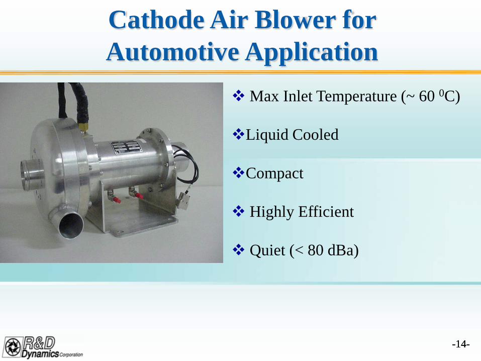
Cathode Air Blower for Automotive Application
Max Inlet Temperature (~ 60 0C)
Liquid Cooled
Compact
Highly Efficient
Quiet (< 80 dBa)
-15--15-
2. FOIL GAS BEARING SUPPORTED CATHODE/ANODE RECYCLE BLOWERS
for LARGE MEGAWATT SIZE SOFC POWER
PLANTS

-16--16-
Specification
Process Gas 7.43% H2, 5.46% CO, 41.55% CO2, 44.13% H2O, 1.43% N2 mole fraction
Molecular Weight 28.31
Specific Heat Ratio 1.22
Inlet Pressure 15.31 psia
Outlet Pressure 15.77 psia
Pressure Rise 12 inches of water
Inlet Temperature 825 C (1517 F)
Flow 185 lbm/min
Input Voltage 480 Vac
-17--17-
Accomplishments A suitable specification was chosen for design of the blower in discussion
with SECA members.
A hermetically sealed blower concept that can be used dually as a Cathodeand Anode recycle blower was developed.
The blower being developed has following features:
High Temperature Capable (≥ 850 C)
Highly Efficient ( >60%)
Reliable (design life > 40,000 hours)
Contamination Free
Maintenance Free
Variable Speed with High Turn Down Ratio (> 2:1)
Affordable
Scalable
-18--18-
Accomplishments (Cont’d)
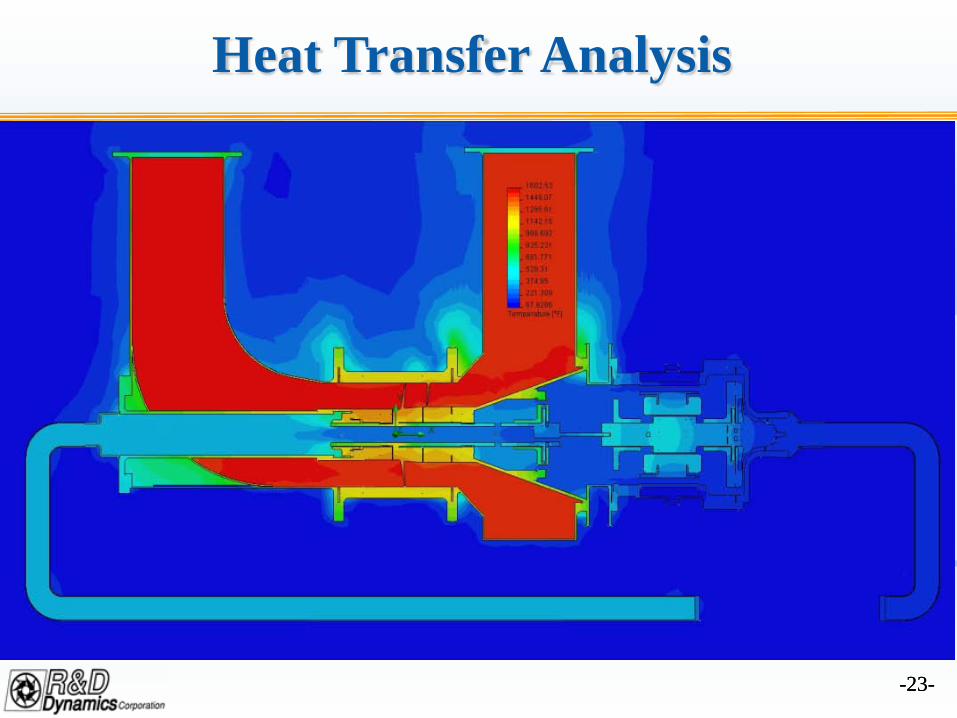
Detailed heat transfer analysis of the blower completed.
Detailed mechanical analysis and design of the blower completed.
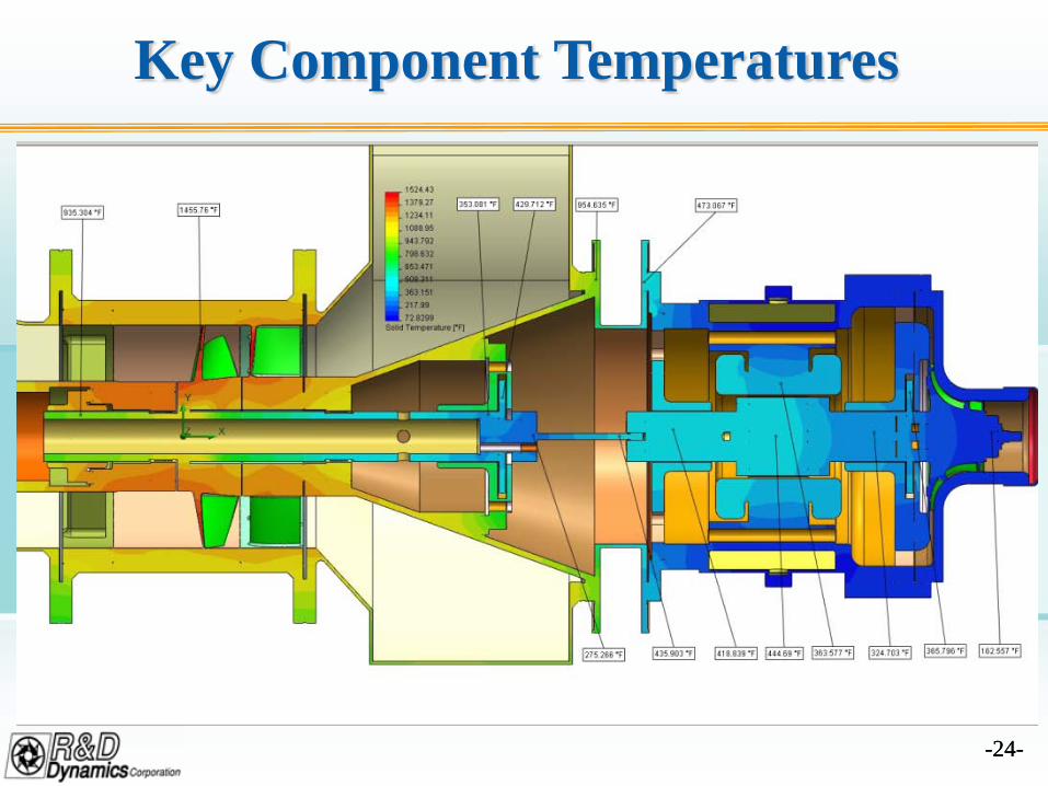
High temperature materials were selected from detailed analysis.
Detailed drawings of the blower were prepared for manufacturing.
Long lead items such as motor lamination and magnets weremanufactured.
Test plan and assembly methods are being developed for testing of theblower at end of this year.
-19--19-
Key Issues
High Temperature Capable (up to 850 C)
Affordable
Highly Efficient
No Anode Gas Leakage
No Metal Outgassing
Low Lifecycle Cost
No Oil or Grease Contamination of Process Gas
Scalable to other Sizes
Maintenance Free
Low Noise
-20--20-
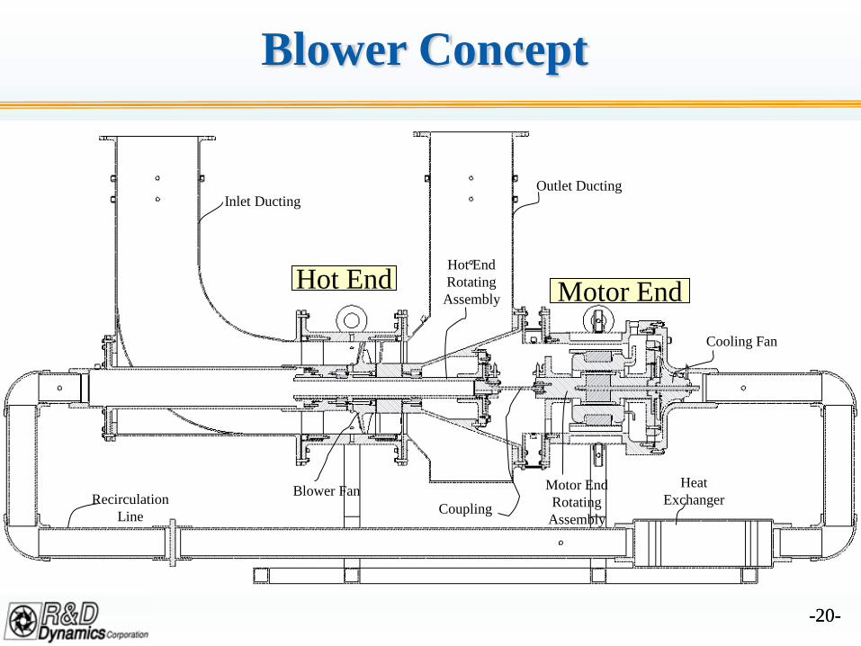
Blower Concept
Inlet DuctingOutlet Ducting
Hot End Motor EndCooling Fan
Recirculation Line
Heat ExchangerBlower Fan
Coupling
Hot End Rotating
Assembly
Motor End Rotating
Assembly
-21--21-
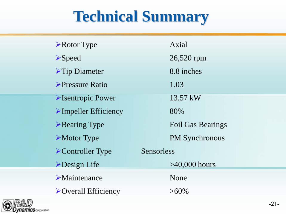
Technical SummaryRotor Type Axial
Speed 26,520 rpm
Tip Diameter 8.8 inches
Pressure Ratio 1.03
Isentropic Power 13.57 kW
Impeller Efficiency 80%
Bearing Type Foil Gas Bearings
Motor Type PM Synchronous
Controller Type Sensorless
Design Life >40,000 hours
Maintenance None
Overall Efficiency >60%
-22--22-
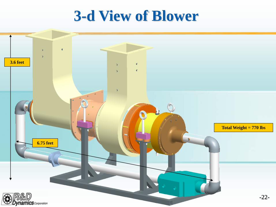
3-d View of Blower
6.75 feet
3.6 feet
Total Weight = 770 lbs
-23--23-
Heat Transfer Analysis
-24--24-
Key Component Temperatures
-25--25-
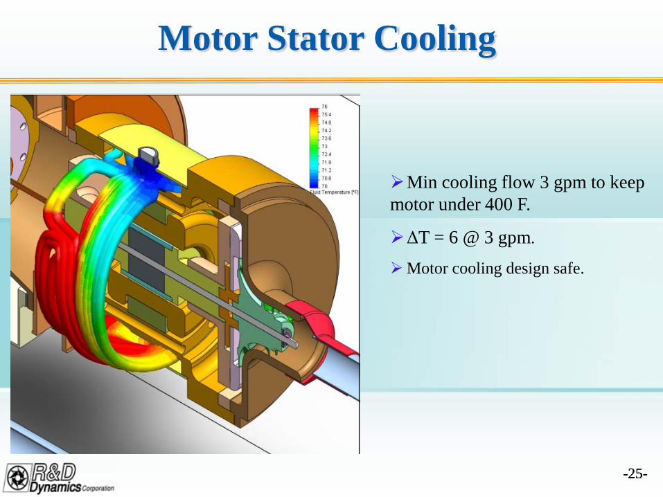
Motor Stator Cooling
Min cooling flow 3 gpm to keep motor under 400 F.
ΔT = 6 @ 3 gpm.
Motor cooling design safe.
-26--26-
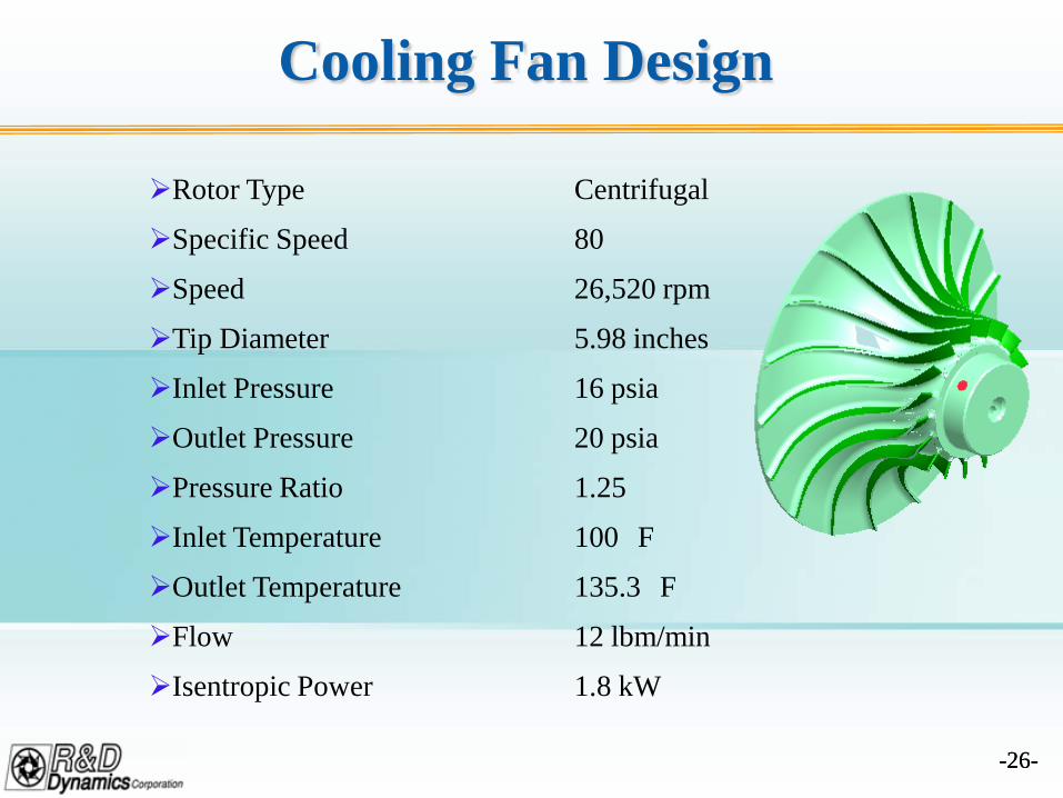
Cooling Fan Design
Rotor Type Centrifugal
Specific Speed 80
Speed 26,520 rpm
Tip Diameter 5.98 inches
Inlet Pressure 16 psia
Outlet Pressure 20 psia
Pressure Ratio 1.25
Inlet Temperature 100 F
Outlet Temperature 135.3 F
Flow 12 lbm/min
Isentropic Power 1.8 kW
-27--27-
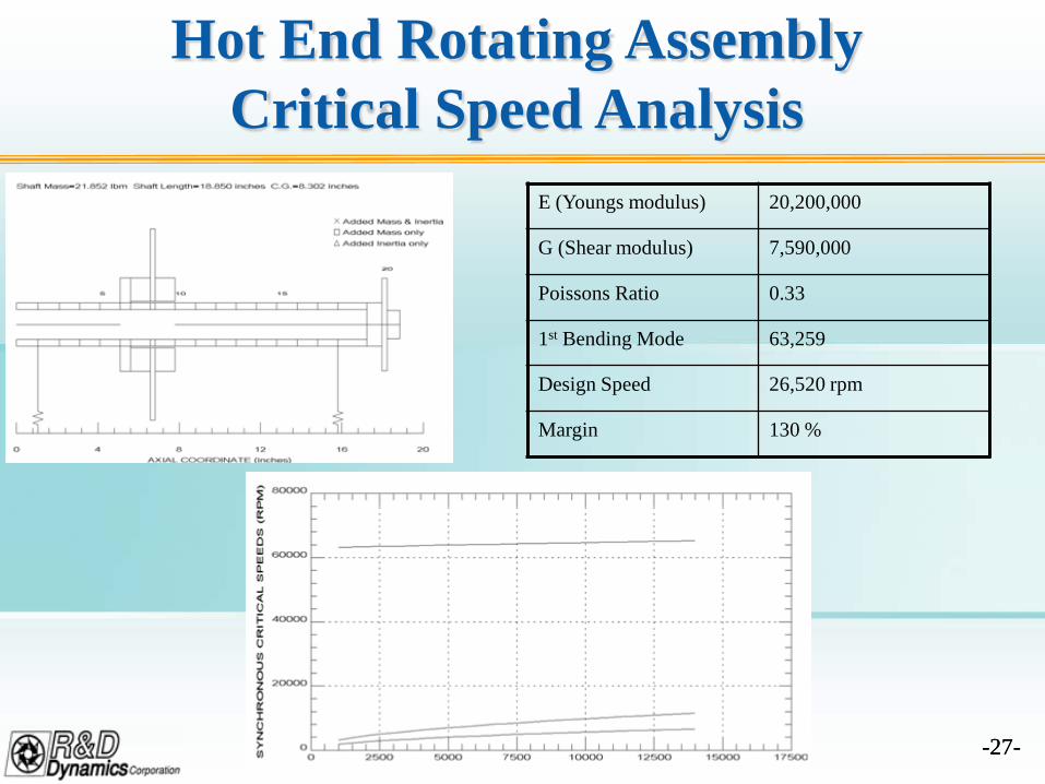
Hot End Rotating AssemblyCritical Speed Analysis
E (Youngs modulus) 20,200,000
G (Shear modulus) 7,590,000
Poissons Ratio 0.33
1st Bending Mode 63,259
Design Speed 26,520 rpm
Margin 130 %
-28--28-
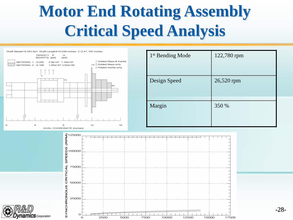
Motor End Rotating AssemblyCritical Speed Analysis
1st Bending Mode 122,780 rpm
Design Speed 26,520 rpm
Margin 350 %
-29--29-
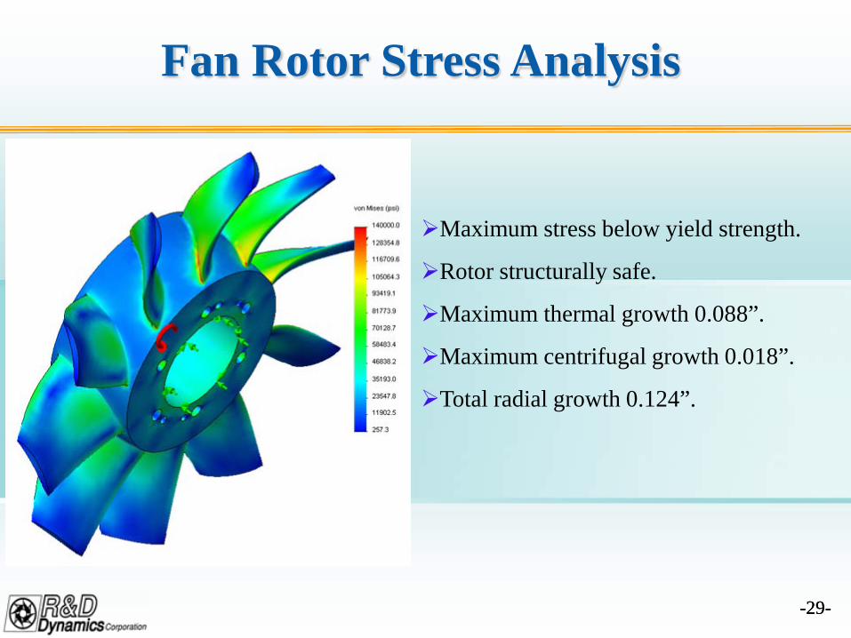
Fan Rotor Stress Analysis
Maximum stress below yield strength.
Rotor structurally safe.
Maximum thermal growth 0.088”.
Maximum centrifugal growth 0.018”.
Total radial growth 0.124”.
-30--30-
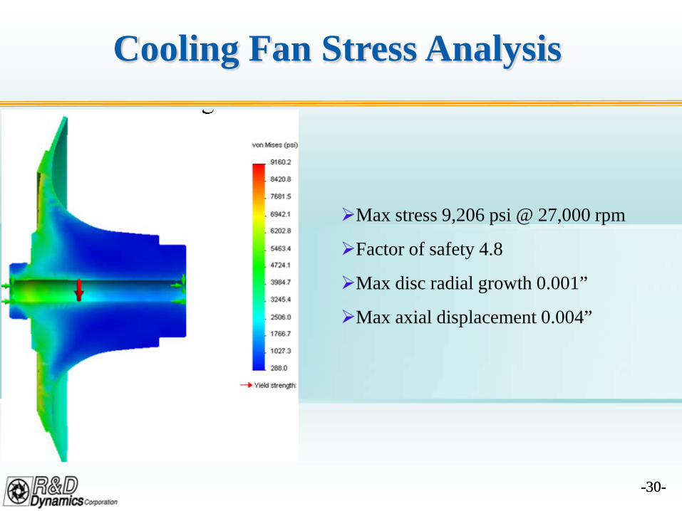
Cooling Fan Stress Analysis
Max stress 9,206 psi @ 27,000 rpm
Factor of safety 4.8
Max disc radial growth 0.001”
Max axial displacement 0.004”
-31--31-
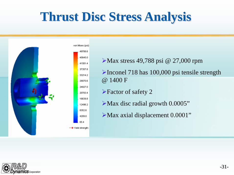
Thrust Disc Stress Analysis
Max stress 49,788 psi @ 27,000 rpm
Inconel 718 has 100,000 psi tensile strength @ 1400 F
Factor of safety 2
Max disc radial growth 0.0005”
Max axial displacement 0.0001”
-32--32-
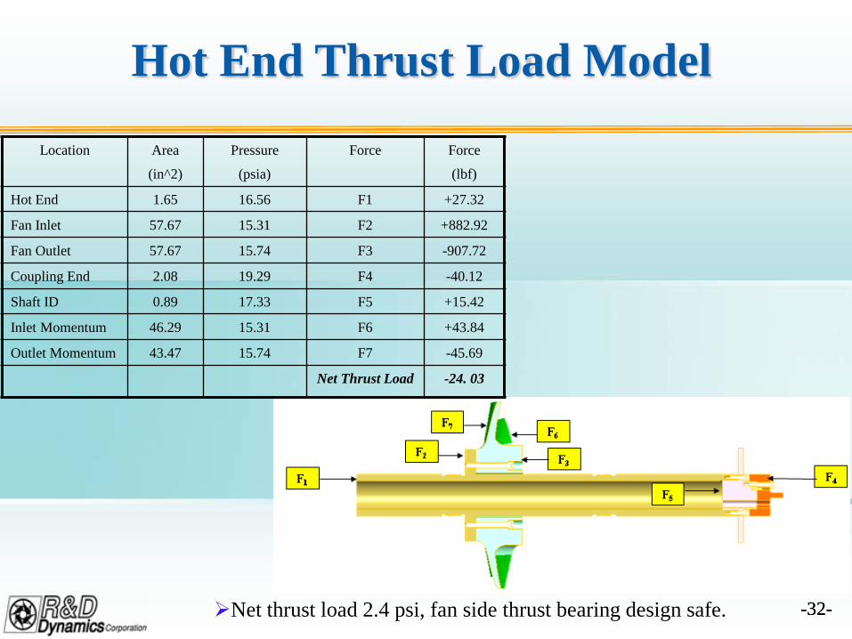
Hot End Thrust Load Model
Location Area
(in^2)
Pressure
(psia)
Force Force
(lbf)
Hot End 1.65 16.56 F1 +27.32
Fan Inlet 57.67 15.31 F2 +882.92
Fan Outlet 57.67 15.74 F3 -907.72
Coupling End 2.08 19.29 F4 -40.12
Shaft ID 0.89 17.33 F5 +15.42
Inlet Momentum 46.29 15.31 F6 +43.84
Outlet Momentum 43.47 15.74 F7 -45.69
Net Thrust Load -24. 03
Net thrust load 2.4 psi, fan side thrust bearing design safe.
-33--33-
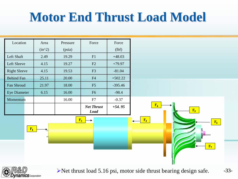
Motor End Thrust Load Model
Net thrust load 5.16 psi, motor side thrust bearing design safe.
Location Area
(in^2)
Pressure
(psia)
Force Force
(lbf)
Left Shaft 2.49 19.29 F1 +48.03
Left Sleeve 4.15 19.27 F2 +79.97
Right Sleeve 4.15 19.53 F3 -81.04
Behind Fan 25.11 20.00 F4 +502.22
Fan Shroud 21.97 18.00 F5 -395.46
Eye Diameter 6.15 16.00 F6 -98.4
Momentum 16.00 F7 -0.37
Net Thrust Load
+54. 95
-34--34-
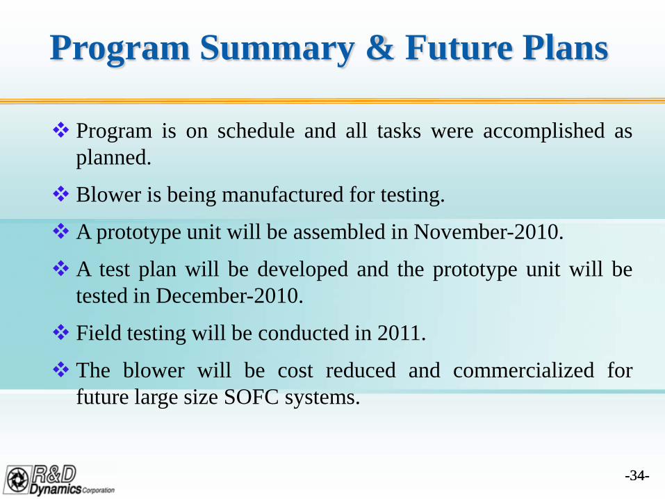
Program Summary & Future Plans
Program is on schedule and all tasks were accomplished asplanned.
Blower is being manufactured for testing.
A prototype unit will be assembled in November-2010.
A test plan will be developed and the prototype unit will betested in December-2010.
Field testing will be conducted in 2011.
The blower will be cost reduced and commercialized forfuture large size SOFC systems.
-35--35-
3. LOW COST CATHODE BLOWER
-36--36-
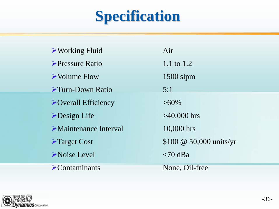
Specification
Working Fluid Air
Pressure Ratio 1.1 to 1.2
Volume Flow 1500 slpm
Turn-Down Ratio 5:1
Overall Efficiency >60%
Design Life >40,000 hrs
Maintenance Interval 10,000 hrs
Target Cost $100 @ 50,000 units/yr
Noise Level <70 dBa
Contaminants None, Oil-free
-37--37-
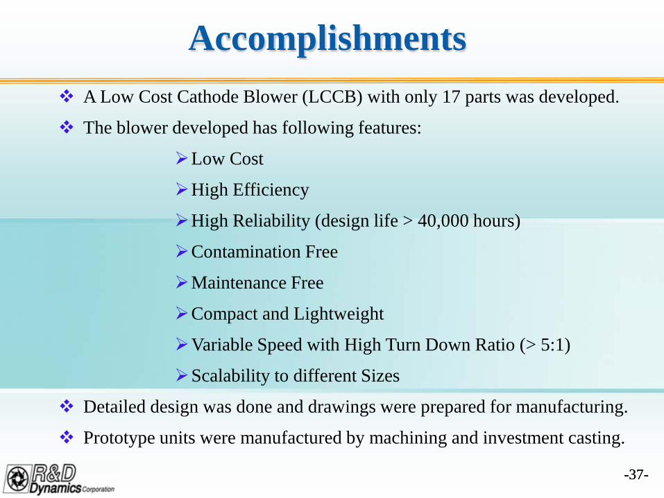
Accomplishments A Low Cost Cathode Blower (LCCB) with only 17 parts was developed.
The blower developed has following features:
Low Cost
High Efficiency
High Reliability (design life > 40,000 hours)
Contamination Free
Maintenance Free
Compact and Lightweight
Variable Speed with High Turn Down Ratio (> 5:1)
Scalability to different Sizes
Detailed design was done and drawings were prepared for manufacturing.
Prototype units were manufactured by machining and investment casting.
-38--38-
Accomplishments (Cont’d)
Prototype units were assembled for performance testing.
A performance test rig was fabricated for testing.
The blower units were tested and test data analyzed.
Acoustic testing of the blower was completed.
Preliminary quotes were received for pre-production quantities and vendorbase were developed for volume production.
SECA members were informed of advancements made in developing thelow cost blower and support from SECA members was received for systemtesting the blower after completion of development.
-39--39-
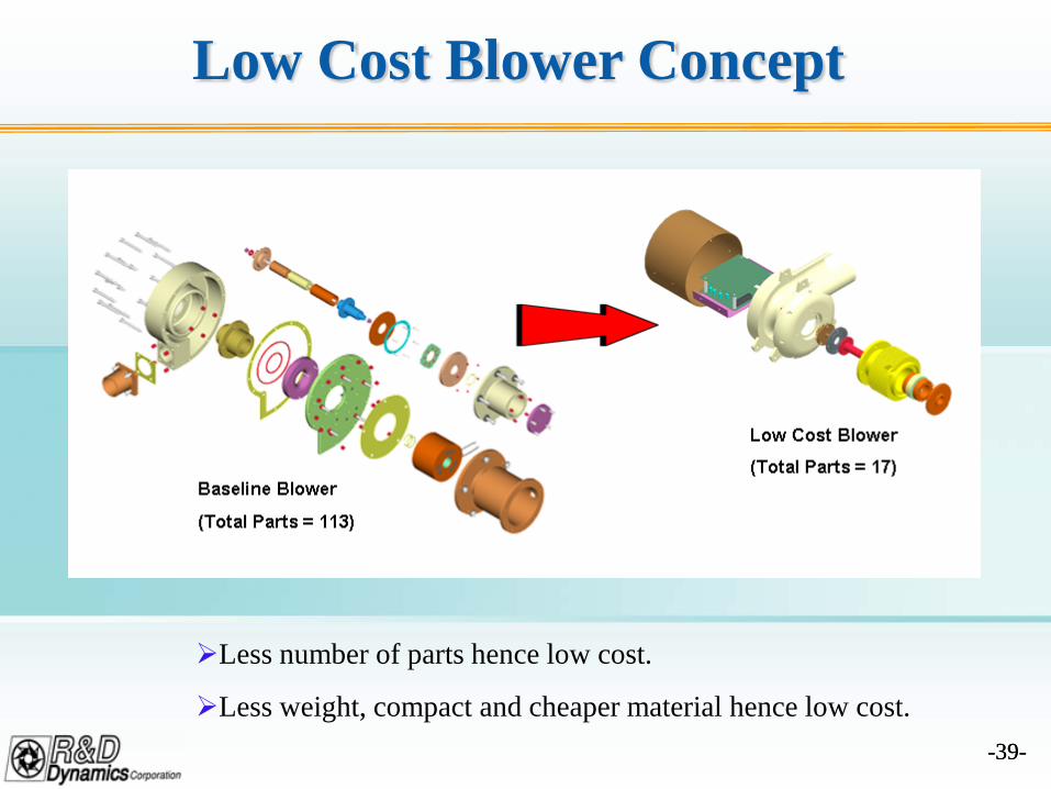
Low Cost Blower Concept
Less number of parts hence low cost.
Less weight, compact and cheaper material hence low cost.
-40--40-
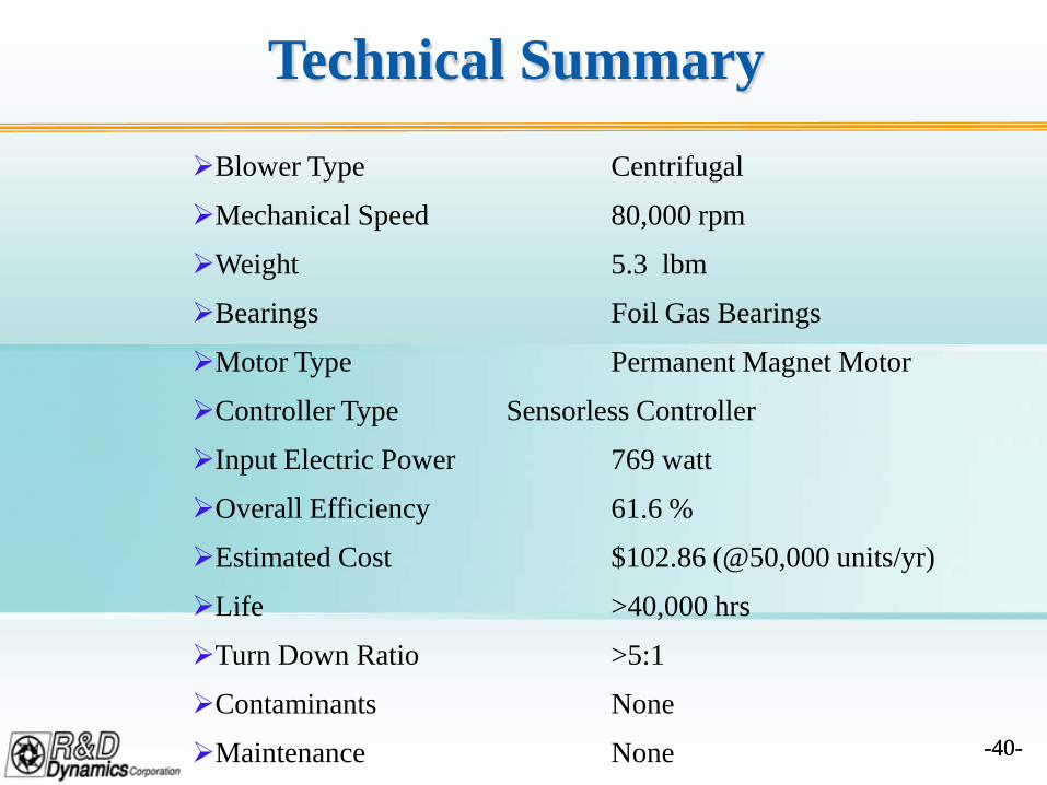
Technical Summary
Blower Type Centrifugal
Mechanical Speed 80,000 rpm
Weight 5.3 lbm
Bearings Foil Gas Bearings
Motor Type Permanent Magnet Motor
Controller Type Sensorless Controller
Input Electric Power 769 watt
Overall Efficiency 61.6 %
Estimated Cost $102.86 (@50,000 units/yr)
Life >40,000 hrs
Turn Down Ratio >5:1
Contaminants None
Maintenance None
-41--41-
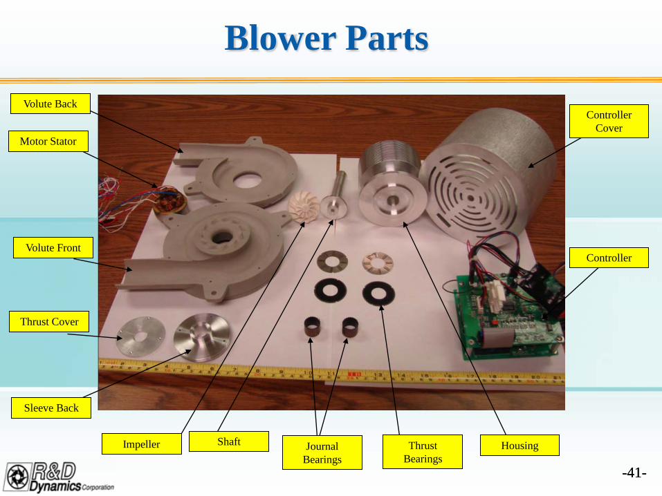
Blower PartsVolute Back
Motor Stator
Volute Front
Thrust Cover
Sleeve Back
Impeller Shaft Journal Bearings
Thrust Bearings
Housing
Controller
Controller Cover
-42--42-
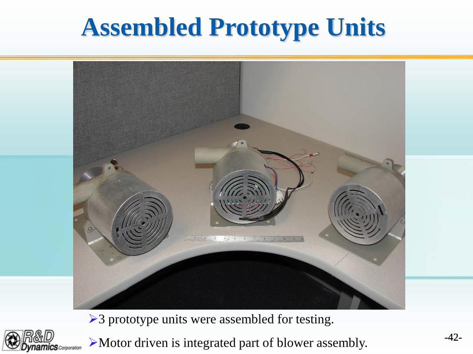
Assembled Prototype Units
3 prototype units were assembled for testing.
Motor driven is integrated part of blower assembly.
-43--43-
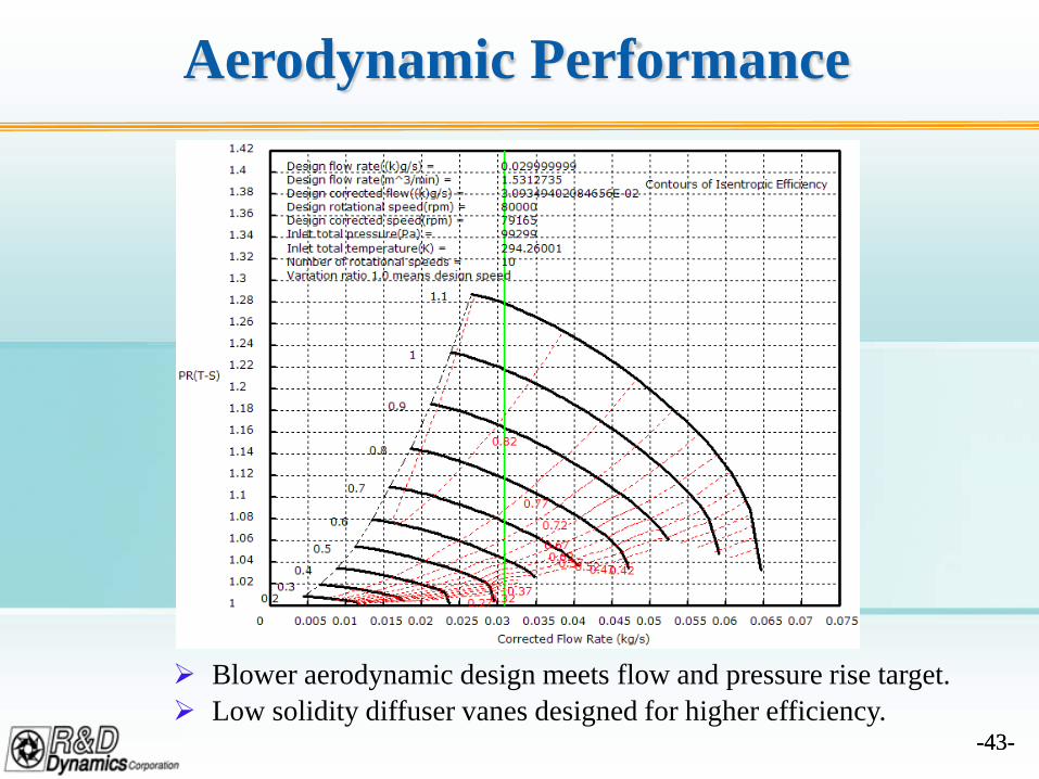
Aerodynamic Performance
Blower aerodynamic design meets flow and pressure rise target. Low solidity diffuser vanes designed for higher efficiency.
-44--44-
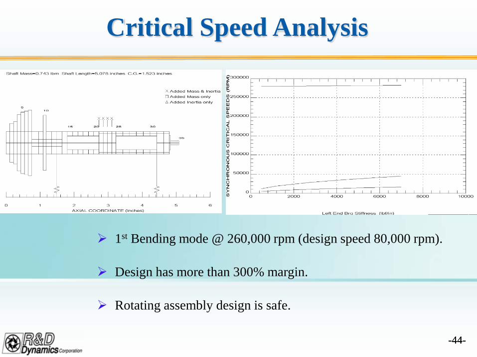
Critical Speed Analysis
1st Bending mode @ 260,000 rpm (design speed 80,000 rpm).
Design has more than 300% margin.
Rotating assembly design is safe.
-45--45-
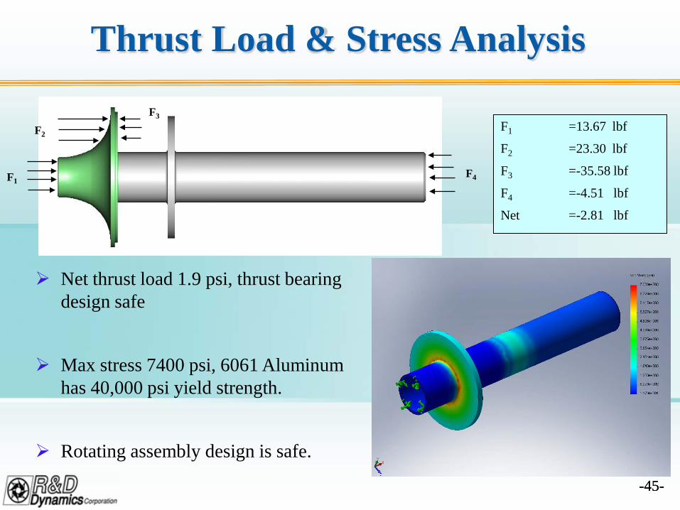
Thrust Load & Stress Analysis
F1
F2
F3
F4
F1 =13.67 lbf
F2 =23.30 lbf
F3 =-35.58 lbf
F4 =-4.51 lbf
Net =-2.81 lbf
Net thrust load 1.9 psi, thrust bearing design safe
Max stress 7400 psi, 6061 Aluminum has 40,000 psi yield strength.
Rotating assembly design is safe.
-46--46-
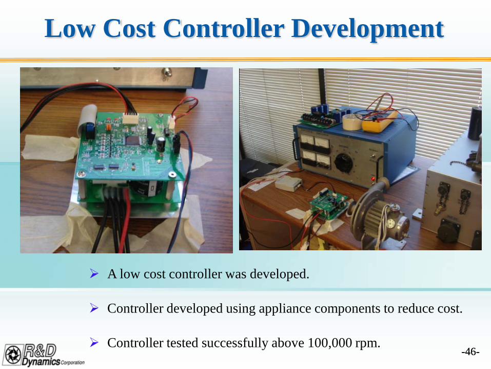
Low Cost Controller Development
A low cost controller was developed.
Controller developed using appliance components to reduce cost.
Controller tested successfully above 100,000 rpm.
-47--47-
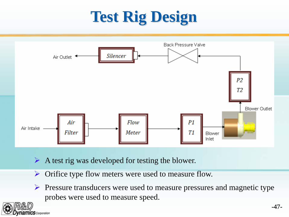
Test Rig Design
A test rig was developed for testing the blower.
Orifice type flow meters were used to measure flow.
Pressure transducers were used to measure pressures and magnetic type probes were used to measure speed.
-48--48-
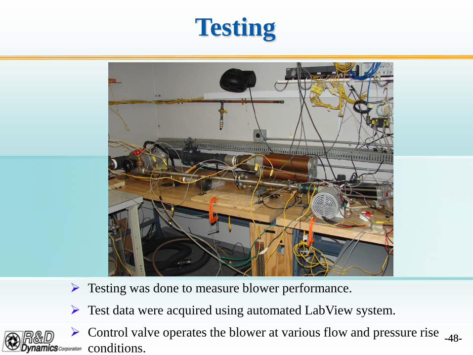
Testing
Testing was done to measure blower performance.
Test data were acquired using automated LabView system.
Control valve operates the blower at various flow and pressure rise conditions.
-49--49-
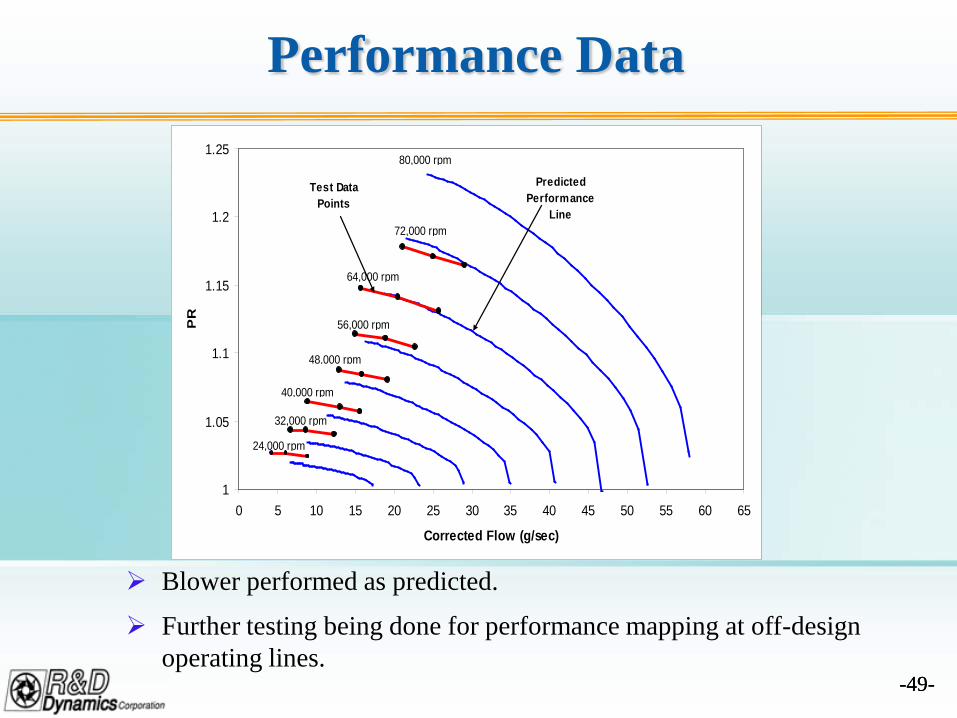
Performance Data
1
1.05
1.1
1.15
1.2
1.25
0 5 10 15 20 25 30 35 40 45 50 55 60 65
Corrected Flow (g/sec)
PR
24,000 rpm
32,000 rpm
40,000 rpm
48,000 rpm
56,000 rpm
64,000 rpm
72,000 rpm
80,000 rpm
Predicted Performance
Line
Test Data Points
Blower performed as predicted.
Further testing being done for performance mapping at off-design operating lines.
-50--50-
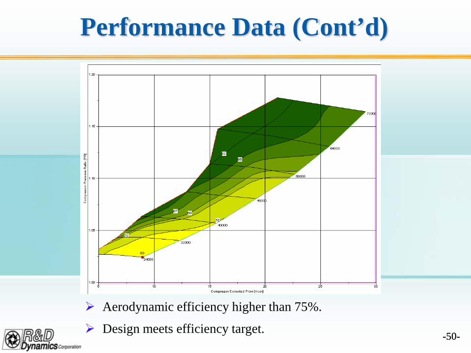
Performance Data (Cont’d)
Aerodynamic efficiency higher than 75%.
Design meets efficiency target.
-51--51-
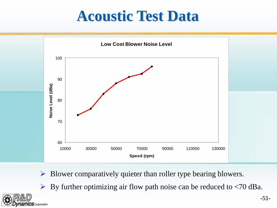
Acoustic Test DataLow Cost Blower Noise Level
60
70
80
90
100
10000 30000 50000 70000 90000 110000 130000
Speed (rpm)
Nois
e Le
vel (
dBa)
Blower comparatively quieter than roller type bearing blowers.
By further optimizing air flow path noise can be reduced to <70 dBa.
-52--52-
Program Summary & Future Plans
The blower development and testing has proved viability of areliable, energy efficient and low cost blower for SOFCsystems.
Further optimization of the blower is being performed toimprove performance and to meet all specifications.
SECA members have extended their support to test the blowerin their SOFC systems.
The further optimized blower will be system tested andcommercialized.
-53--53-
Overall Conclusion
R&D Dynamics has become a complete blowersolution provider for all fuel cell system industry.
Particularly in last 5 years working closely with DOEand SECA members the phase is shifting fromprototype manufacturing to volume production.
R&D Dynamics blowers have been field testedsuccessfully for thousands of hours all around theworld.
R&D Dynamics blowers provide energy efficient,reliable, contamination free and maintenance freeoperation.
-54--54-
Overall Conclusion (Cont’d)
Currently R&D Dynamics is working on setting upproduction line in the new 75,000 Sq.ft facility andestablishing vendor supply base for volumemanufacturing.
R&D Dynamics is committed to deliver qualityblowers for fuel cell system manufacturers whichmeets their performance and cost goals.
-55-
Acknowledgement
R&D Dynamics would like to thank DOE andSECA members for their continued support.