Embed Size (px)
Citation preview
Progress In Electromagnetics Research M, Vol. 19, 183–195, 2011
FOCUSING GROUND PENETRATING RADAR IMAGESWITH VERTICAL OFFSET FILTERING
A. Benter*, W. Moore, and M. Antolovich
School of Computing and Mathematics, Charles Sturt University,Panorama Avenue, Bathurst 2795, Australia
Abstract—Existing focusing techniques for Ground PenetratingRadar (GPR) rely on migration of 2D or 3D images to removeclutter originating from objects laterally offset from the antenna. Inapplications requiring real-time focusing, a method operating on 1Dtrace data is required. This paper presents a new algorithm for focusingGPR images, the Vertical Offset Filter (VOF), using simulated and realGPR data.
1. INTRODUCTION
GPR provides a mechanism to detect reflected signals from subsurfaceobjects and changes in the electromagnetic characteristics of theground material. Typically, the subsurface environment under studyrequires the GPR antenna to be moved horizontally across the surfaceof the ground. At individual locations, a signal ‘trace’ of reflections(an A-scan) from features illuminated by the GPR antenna is recorded.Multiple traces are compiled to form a B-scan. B-scans can then beprocessed to form a 3-dimensional profile of the underground features(referred to as a C-scan).
GPR has been used for archaeological discovery [1], non-destructive testing of engineering structures [2, 3], examination ofground soil characteristics and voids [4], and detection of buried landmines [5]. These activities utilise the GPR antenna in the typical wayby moving parallel to the ground surface, obtaining signals with acommon ground offset.
A significant limitation of GPR in such an application is clutter.Reference [6] suggests that the primary goal of signal processing is to
Received 2 June 2011, Accepted 23 July 2011, Scheduled 31 July 2011* Corresponding author: Allen Benter ([email protected]).
184 Benter, Moore, and Antolovich
remove or reduce clutter from the GPR return signal. Due to the broadbeam width of the GPR signal, clutter is the result of reflections fromobjects within the beam other than the target, including those offsetfrom the position of the antenna, and may include objects directlybeneath the antenna.
A major source of clutter is the reflection from the surface. Inorder to reduce this, the antenna is, in a typical application, closelycoupled to the surface during acquisition to direct the signal into theground. Close coupling also has the effect of focusing the signal [7].While it is normally desirable to achieve a close coupling betweenantenna and the ground surface, in some situations this is not possible.
One application of GPR that is of particular interest to the miningindustry and the authors is to identify the presence of large rocks inthe rubble formation at the draw point of an underground mine. Afterblasting, the fractured ore is collected from the draw point and takento the primary crusher. Fragments larger than the primary crushercan accommodate may be hidden from view beneath the surface at thedraw point. Due to the very course nature of the ore presentation, it isnot possible, in a production setting, to achieve a close coupling withthe ore surface. Whilst elevating the antenna results in a larger initialreflection from the surface, it also has the effect of reducing the signalresponse from subsurface objects that are horizontally offset from theantenna [7].
This paper presents a novel method to focus GPR signals. Thefollowing sections will describe a new algorithm for removing featureswithin the beam of the GPR system, but not directly beneath theantenna. Section 2 will detail the VOF focusing algorithm; Section 3will show simulated results using MatGPR [8]. Section 4 will thenlook at the application of the algorithm to real GPR data undercontrolled conditions, followed by Section 5 showing further work inthe application and development of this algorithm.
2. FILTERING ALGORITHMS
Most GPR systems use a broad beam antenna, detecting reflectedenergy from subsurface structures. Given the broad beam width,objects illuminated by the antenna pulse, including those offsethorizontally from the antenna position, contribute to the radar signal.Hence, the interpretation of a single time response is limited to therange of an object [9]. No information regarding horizontal offset canbe inferred from the signal.
As the antenna is moved across the surface, the range to theilluminated object also changes — firstly decreasing as the antenna
Progress In Electromagnetics Research M, Vol. 19, 2011 185
approaches until the shortest range is recorded when the antennais directly above the object, then increasing as the antenna movespast and beyond the object. This change is depicted in B-scans as ahyperbola.
This hyperbole structure is an unfocused depiction of thescatterer [10] which is removed using various migration processes.These are generally derived from seismic imaging research, and includethe maximum convexity migration algorithm. The maximum convexitymigration algorithm works by comparing each and every sample pointacross the entire B-scan. Each sample point that falls on a curve ofmaximum convexity is considered to be a reflection from the samepoint, and can be removed [11]. Thus, knowing the propagationspeed of the signal through the media, or assuming a constant speedas required by maximum convexity migration, we can remove thehyperbole. In the case where we do not know the propagation speed,or the speed is variable, we need another method.
Recording signal returns from objects within the field of view, butoffset from the antenna clutters the signal return from objects directlybeneath the antenna. The hyperbole structure also contribute to theclutter in an image by interfering with the signal return in adjacenttraces. Removing surface clutter from images using time gating hasthe undesired effect of removing the reflections from shallow objects.Averaging also works to remove coherent clutter, but is ineffectivein inhomogeneous material. Removal of incoherent clutter is basedon a statistical knowledge of the background material, or the target.In inhomogeneous material, the properties will vary. Using a prioriknowledge of the target reflection [12] or shape [13] to build a referencesignal is less useful when the target shape is unknown.
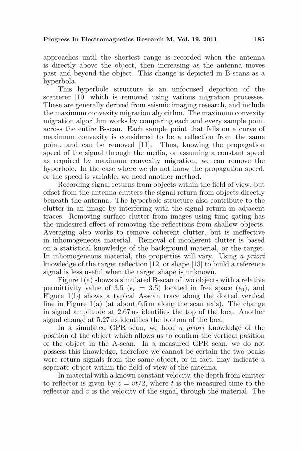
Figure 1(a) shows a simulated B-scan of two objects with a relativepermittivity value of 3.5 (εr = 3.5) located in free space (ε0), andFigure 1(b) shows a typical A-scan trace along the dotted verticalline in Figure 1(a) (at about 0.5 m along the scan axis). The changein signal amplitude at 2.67 ns identifies the top of the box. Anothersignal change at 5.27 ns identifies the bottom of the box.
In a simulated GPR scan, we hold a priori knowledge of theposition of the object which allows us to confirm the vertical positionof the object in the A-scan. In a measured GPR scan, we do notpossess this knowledge, therefore we cannot be certain the two peakswere return signals from the same object, or in fact, may indicate aseparate object within the field of view of the antenna.
In material with a known constant velocity, the depth from emitterto reflector is given by z = vt/2, where t is the measured time to thereflector and v is the velocity of the signal through the material. The
186 Benter, Moore, and Antolovich
(a) (b)
Figure 1. Synthetic scan of two objects (εr = 3.5) located in freespace (v = 0.29979m/ns). (a) B-Scan, (b) A-scan.
typical hyperbolic pattern of a point reflector in motion across a B-scanis given by equation (from reference [6])
zi =√
(xi − x0)2 + z20 (1)
Ideally, we would have a pencil-thin beam to illuminate only thoseobjects directly beneath the antenna. Given the wide-beam of theradar signal, if we could determine where in the radar beam the signalreturn originated, we could filter signal returns from laterally offsetobjects. With a single radar measure, we cannot determine the lateraloffset position, and so Equation (1) remains as a range equation.However, if we record a trace, and move the antenna some distanceh along the signal propagation path (that is, away from the ground)we can expect objects that are located directly beneath the antennato also move h in the trace, such that
zi = (z0 + h) (2)
Equation (1) thus becomes
zi =√
(xi − x0)2 + (z0 + h)2 (3)
such that if zi 6= z0 + h then the point reflector is not located on thesignal propagation path and zi can be clipped from the trace. Thus,the trace data only identifies objects directly beneath the antenna.Whilst not determining the lateral offset to objects, we are excludingthose objects clearly not located directly beneath the antenna. We pro-pose a new method called the Vertical Offset Filter, as shown below:
Progress In Electromagnetics Research M, Vol. 19, 2011 187
foreach A-Scan xi doforeach Offset A-Scan xi,k do
forall Sample Values zi,k doif zi,k is a signal peak then
si,k = 1;else
si,k = 0;end
endendAlign k scans by vertical offset h;zi =
∑mk=1 si,k;
if zi == m thenzi = 1 //keep common signal peak;
elsezi = 0 //discard signal peak;
endendAlgorithm 1: The Vertical Offset Filter (VOF) algorithm.
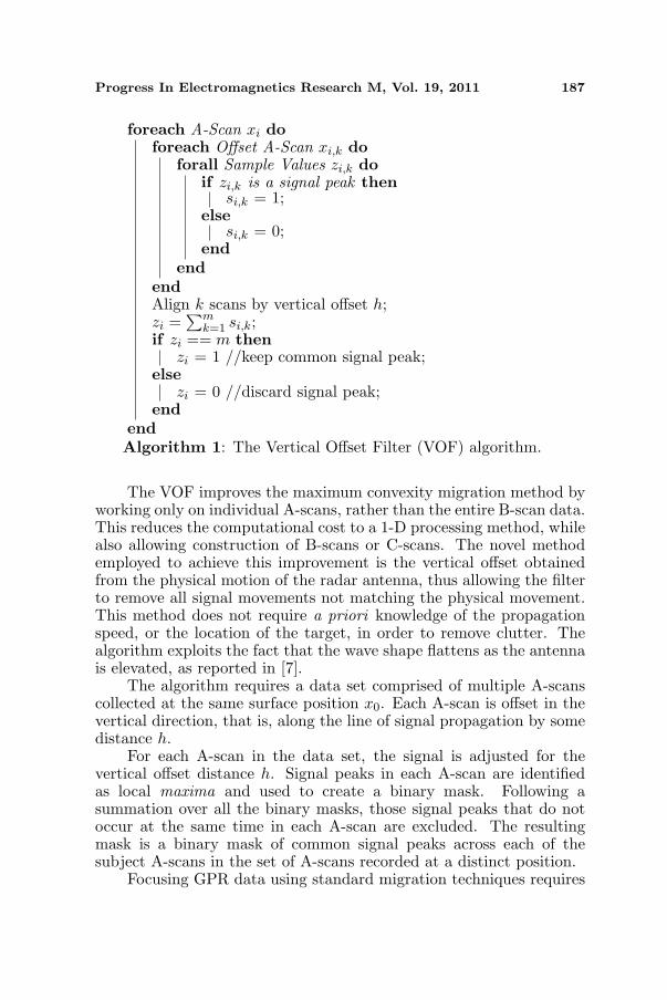
The VOF improves the maximum convexity migration method byworking only on individual A-scans, rather than the entire B-scan data.This reduces the computational cost to a 1-D processing method, whilealso allowing construction of B-scans or C-scans. The novel methodemployed to achieve this improvement is the vertical offset obtainedfrom the physical motion of the radar antenna, thus allowing the filterto remove all signal movements not matching the physical movement.This method does not require a priori knowledge of the propagationspeed, or the location of the target, in order to remove clutter. Thealgorithm exploits the fact that the wave shape flattens as the antennais elevated, as reported in [7].
The algorithm requires a data set comprised of multiple A-scanscollected at the same surface position x0. Each A-scan is offset in thevertical direction, that is, along the line of signal propagation by somedistance h.
For each A-scan in the data set, the signal is adjusted for thevertical offset distance h. Signal peaks in each A-scan are identifiedas local maxima and used to create a binary mask. Following asummation over all the binary masks, those signal peaks that do notoccur at the same time in each A-scan are excluded. The resultingmask is a binary mask of common signal peaks across each of thesubject A-scans in the set of A-scans recorded at a distinct position.
Focusing GPR data using standard migration techniques requires
188 Benter, Moore, and Antolovich
the capture of B-scans or C-scans prior to migration processing. TheVOF algorithm operates on A-scans and, as long as the antenna ismoved perpendicular to the ground, could operate in real-time toremove these artifacts.
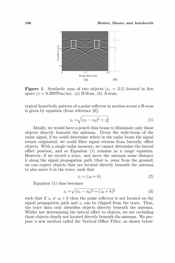
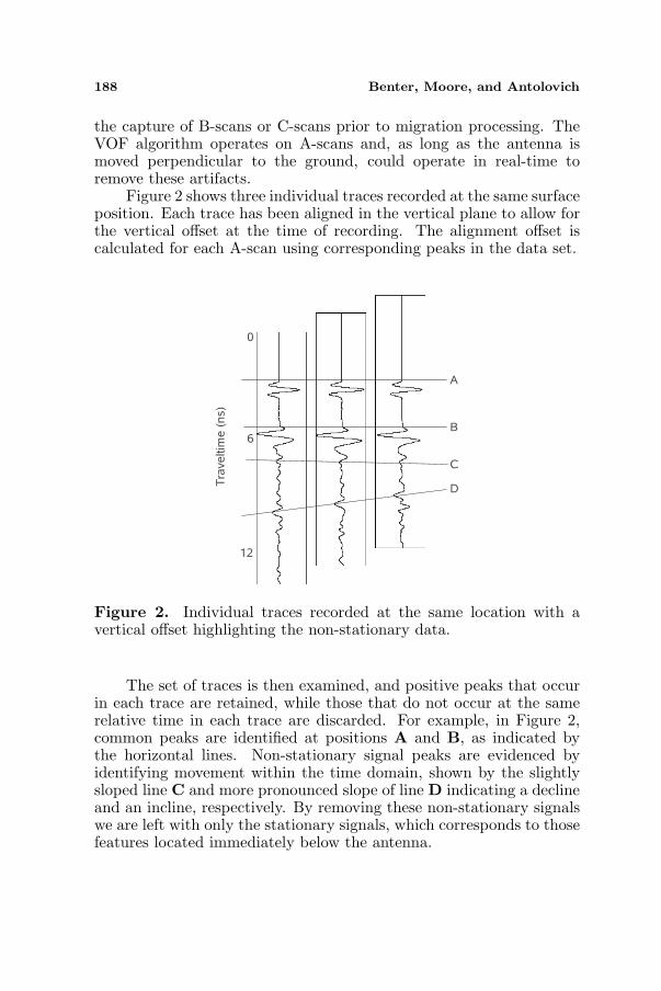
Figure 2 shows three individual traces recorded at the same surfaceposition. Each trace has been aligned in the vertical plane to allow forthe vertical offset at the time of recording. The alignment offset iscalculated for each A-scan using corresponding peaks in the data set.
Figure 2. Individual traces recorded at the same location with avertical offset highlighting the non-stationary data.
The set of traces is then examined, and positive peaks that occurin each trace are retained, while those that do not occur at the samerelative time in each trace are discarded. For example, in Figure 2,common peaks are identified at positions A and B, as indicated bythe horizontal lines. Non-stationary signal peaks are evidenced byidentifying movement within the time domain, shown by the slightlysloped line C and more pronounced slope of line D indicating a declineand an incline, respectively. By removing these non-stationary signalswe are left with only the stationary signals, which corresponds to thosefeatures located immediately below the antenna.
Progress In Electromagnetics Research M, Vol. 19, 2011 189
3. SYNTHETIC RESULTS
To demonstrate the algorithm, a GPR scan was synthesised usingMatGPR [8]. The environment described was a 2.0 m wide by 1.0mdeep scan area of free space (v = 0.29979m/ns). The space containedtwo objects of dimension 0.2m×0.2m located at a depth of 0.4 m witha relative permittivity value εr = 3.5. Synthetic scans were producedusing a finite-difference time domain (FDTD) 2D method simulatinga 1200 MHz antenna.
In total, three synthetic scans were simulated over the samesurface path, each with a different vertical offset. The 0.00 m offsetrepresents the initial position of the antenna. The 0.15m and 0.30mvertical offsets were chosen arbitrarily.
Figure 1 shows the raw GPR data obtained and presented as (a)a B-scan and (b) an A-scan through the centre of the left-hand object(represented in the B-scan as a dotted line). Although a very simplesimulation, the images show the hyperbole from the top and bottomof the objects. It is also apparent that the hyperbola of the right-handobject also appears beneath the left-hand object. Hence, the A-scanthrough the left-hand object contains signal response from the right-hand object.
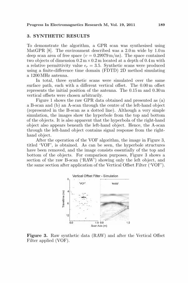
After the operation of the VOF algorithm, the image in Figure 3,titled ‘VOF’, is obtained. As can be seen, the hyperbole structureshave been removed, and the image consists essentially of the top andbottom of the objects. For comparison purposes, Figure 3 shows asection of the raw B-scan (‘RAW’) showing only the left object, andthe same section after application of the Vertical Offset Filter (‘VOF’).
Figure 3. Raw synthetic data (RAW) and after the Vertical OffsetFilter applied (VOF).
190 Benter, Moore, and Antolovich
4. REAL RESULTS
The synthetic experiments were repeated using a 2 GHz Siropulse GPRsystem from CSIRO (Aust). The test environment was assembled byplacing the sample on an 3 mm aluminium plate, with the antennasuspended from a timber rail directly above the sample. The antennawas then run along the rail, recording a B-scan over the sample.
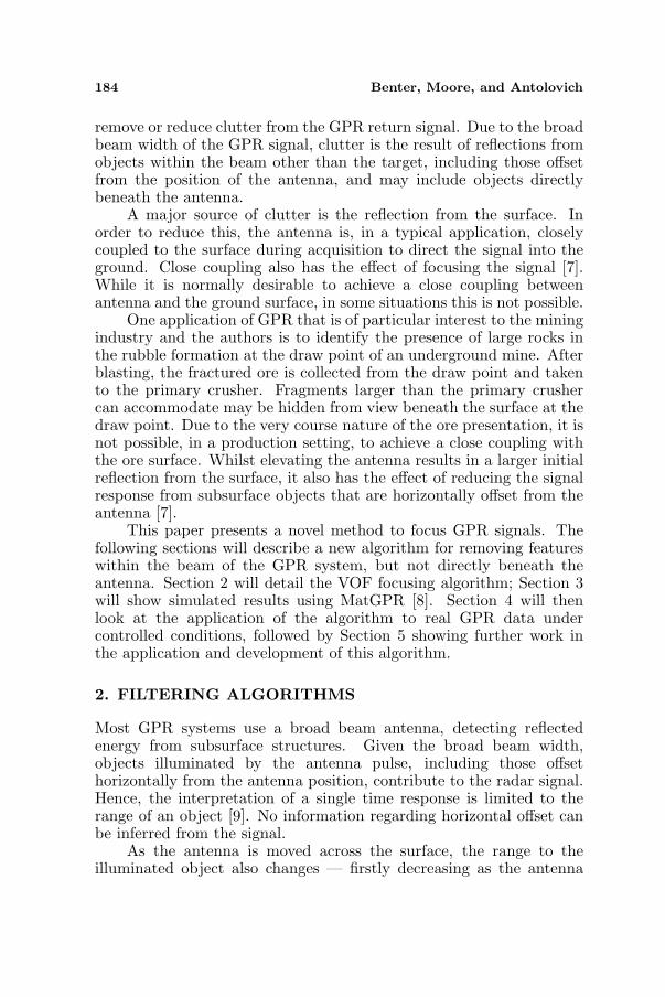
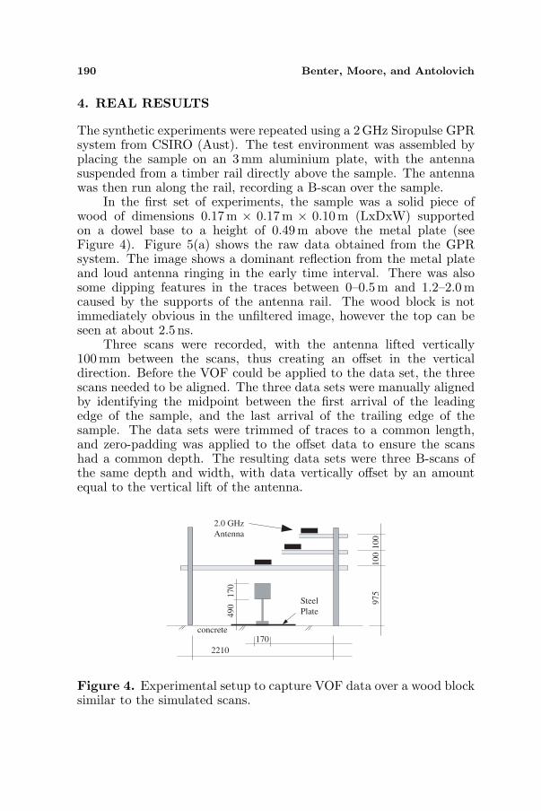
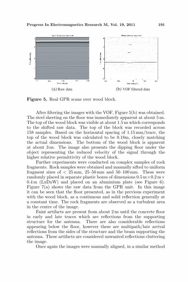
In the first set of experiments, the sample was a solid piece ofwood of dimensions 0.17 m × 0.17m × 0.10m (LxDxW) supportedon a dowel base to a height of 0.49 m above the metal plate (seeFigure 4). Figure 5(a) shows the raw data obtained from the GPRsystem. The image shows a dominant reflection from the metal plateand loud antenna ringing in the early time interval. There was alsosome dipping features in the traces between 0–0.5 m and 1.2–2.0mcaused by the supports of the antenna rail. The wood block is notimmediately obvious in the unfiltered image, however the top can beseen at about 2.5 ns.
Three scans were recorded, with the antenna lifted vertically100mm between the scans, thus creating an offset in the verticaldirection. Before the VOF could be applied to the data set, the threescans needed to be aligned. The three data sets were manually alignedby identifying the midpoint between the first arrival of the leadingedge of the sample, and the last arrival of the trailing edge of thesample. The data sets were trimmed of traces to a common length,and zero-padding was applied to the offset data to ensure the scanshad a common depth. The resulting data sets were three B-scans ofthe same depth and width, with data vertically offset by an amountequal to the vertical lift of the antenna.
2.0 GHz
Antenna
concrete
2210
170
Steel
Plate
490
170
975
100
100
Figure 4. Experimental setup to capture VOF data over a wood blocksimilar to the simulated scans.
Progress In Electromagnetics Research M, Vol. 19, 2011 191
(a) Raw data (b) VOF filtered data
Figure 5. Real GPR scans over wood block.
After filtering the images with the VOF, Figure 5(b) was obtained.The steel sheeting on the floor was immediately apparent at about 5 ns.The top of the wood block was visible at about 1.5 ns which correspondsto the shifted raw data. The top of the block was recorded across158 samples. Based on the horizontal spacing of 1.15mm/trace, thetop of the wood block was calculated to be 0.18m, closely matchingthe actual dimensions. The bottom of the wood block is apparentat about 3 ns. The image also presents the dipping floor under theobject representing the reduced velocity of the signal through thehigher relative permittivity of the wood block.
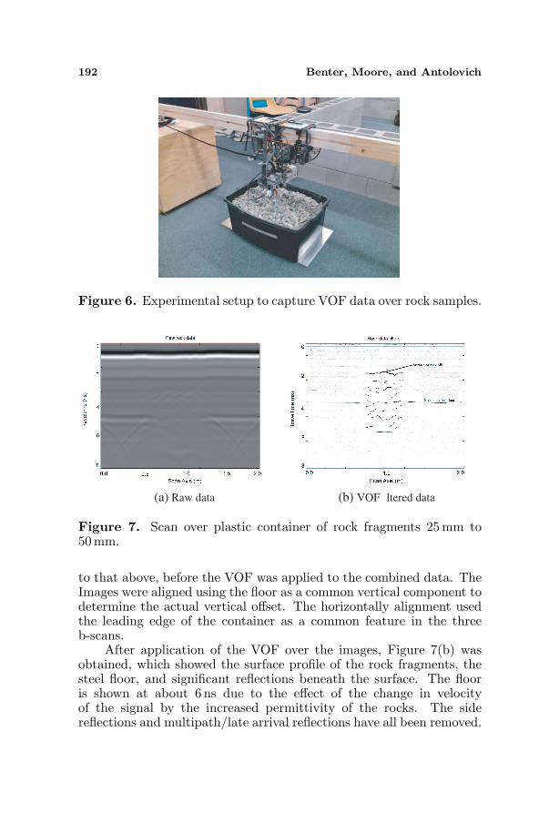
Further experiments were conducted on complex samples of rockfragments. Rock samples were obtained and manually sifted to uniformfragment sizes of < 25 mm, 25–50 mm and 50–100mm. These wererandomly placed in separate plastic boxes of dimensions 0.5m×0.2m×0.4m (LxDxW) and placed on an aluminium plate (see Figure 6).Figure 7(a) shows the raw data from the GPR unit. In this imageit can be seen that the floor presented, as in the previous experimentwith the wood block, as a continuous and solid reflection generally ata constant time. The rock fragments are observed as a turbulent areain the centre of the image.
Faint artifacts are present from about 2 ns until the concrete floorin early and late traces which are reflections from the supportingstructure for the antenna. There are also considerable reflectionsappearing below the floor, however these are multipath/late arrivalreflections from the sides of the structure and the beam supporting theantenna. These artifacts are considered unwanted reflections clutteringthe image.
Once again the images were manually aligned, in a similar method
192 Benter, Moore, and Antolovich
Figure 6. Experimental setup to capture VOF data over rock samples.
(a) Raw data (b) VOF ltered data
Figure 7. Scan over plastic container of rock fragments 25 mm to50mm.
to that above, before the VOF was applied to the combined data. TheImages were aligned using the floor as a common vertical component todetermine the actual vertical offset. The horizontally alignment usedthe leading edge of the container as a common feature in the threeb-scans.
After application of the VOF over the images, Figure 7(b) wasobtained, which showed the surface profile of the rock fragments, thesteel floor, and significant reflections beneath the surface. The flooris shown at about 6 ns due to the effect of the change in velocityof the signal by the increased permittivity of the rocks. The sidereflections and multipath/late arrival reflections have all been removed.
Progress In Electromagnetics Research M, Vol. 19, 2011 193
The image has been augmented to assist interpretation by tracingthe significant reflections from the surface of the rocks, within thecontainer.
The footprint of the antenna beam was approximately 1 m in the xand y directions at the elevations used. The surface profile depicted inthe images corresponded with the surface profile of the rock fragmentsproviding a much finer resolution than the footprint would suggestpossible.
5. DISCUSSION
It has been shown in Figure 3 that the VOF improves the resolution ofthe simulated data, removing clutter from the original. The operationis also very fast over each A-scan data set, and allows construction of B-scans from the filtered data. The algorithm has also been implementedon real GPR data (Figures 5(b) and 7(b)) and showed similar clutterremoval in the filtered B-scan. Further experiments are required todetermine the resolution of the data filtered using VOF, and to refinethe operation to reduce signal decimation.
There is an additional cost associated with using the authorsalgorithm in the acquisition of the data set. The VOF requires atleast 2 identical A-scans with a vertical shift occurring between thetwo scans. This additional acquisition time may be a problem incertain applications. In the particular application under study (seeSection 1) this additional cost can be reduced by using a horizontalarray of antennas and the motion of the image acquisition vehicle.As the vehicle approaches the draw point, the antennas will be offsetin relation to the draw point — equivalent to the vertical offset inFigures 2, 3, 4 and 5. Each set of traces can then be processedindividually, with an adjustment for the offset distance. The processedtrace data can then be compiled to create a B-scan for further imageanalysis.
The real data sets presented in this paper were manually alignedbefore applying the VOF algorithm. In the application presentedabove, data would normally be collected as A-scans. The verticalalignment offset can be easily calculated from either the first arrivalreflection, or using additional sensors, such as a laser sensor. As longas the vehicle is approaching perpendicular to the sample, the datais likely to be horizontally aligned. In other applications, the setupand acquisition of A-scans would need to consider the alignment in thevertical and horizontal planes.
194 Benter, Moore, and Antolovich
6. CONCLUSION
This paper has presented a novel method to focus real and simulatedGPR data. The method focuses the GPR image through the removalof clutter which also removes the hyperbola structure commonlyassociated with GPR data. The resulting image can assist indetermining the size and location of objects directly beneath theantenna. The algorithm is also efficient in processing time, and incertain circumstances can operate in real time on the removal of theseartifacts.
Further analysis of the data is required to demonstratethe resolution achievable under operation of the filter, and thecorrespondence of interior reflections to objects within the targetstructure. Further work is also proposed in automating the algorithmto determine the offset in complex environments.
ACKNOWLEDGMENT
This research is being conducted as part of a research program fundedby Newcrest Mining Ltd. The authors would like to thank the reviewersfor their constructive comments which have improved this paper.
REFERENCES
1. Conyers, L. B. and T. Osburn, “GPR mapping to testanthropological hypotheses: A study from comb wash., utah,american southwest,” 11th International Conference on GroundPenetrating Radar , 2006.
2. Leucci, G., S. Negri, and M. T. Carrozzo, “Ground penentratingradar (GPR): An application for evaluating the state ofmaintenance of the building coating,” Annals of Geophysics,Vol. 46, No. 3, 481–489, 2003.
3. Willett, D., K. Mahboub, and B. Rister, “Accuracy of ground-penetrating radar for pavement-layer thickness analysis,” Journalof Transportation Engineering, Vol. 132, No. 1, 96–103, 2006.
4. Chen, Y. L. and J. J. Chow, “Ground penetrating radar signalprocessing improves mapping accuracy of underground voids andseawater table: An application in deteriorating coastal structure,nanfango port, taiwan,” Environmental Geology , Vol. 53, 445–455,2007.
5. Rappaport, C., M. El-Shenawee, and H. Zhan, “SuppressingGPR clutter from randomly rough ground surfaces to enhance
Progress In Electromagnetics Research M, Vol. 19, 2011 195
nonmetallic mine detection,” Subsurface Sensing Technologies andApplications, Vol. 4, No. 4, 311–326, 2003.
6. Daniels, D., Geound-Penetrating Radar , IET, New York, 2004.7. Bloemenkamp, R. and E. Slob, “The effect of the elevation of
GPR antennas on data quality,” 2nd International Workshop onAdvanced GPR, 2003.
8. Tzanis, A., “Matgpr: A freeware matlab package for the analysisof common-offset GPR data,” Geophysical Research Abstracts,Vol. 8, No. 09448, 2006.
9. Plumb, R. G. and C. Leuschen, “A class of migration algorithmsfor ground penetrating radar data,” IGARSS99 , 2519–2521, 1999.
10. Ozdemir, C., S. Demirci, and E. Yigit, “Practical algorithms tofocus B-scan GPR images: Theory and application to real data,”Progress In Electromagnetic Research B , Vol. 6, 109–122, 2008.
11. Upadhyay, S., Seismic Reflection Processing, Springer, 2007.12. Van Der Merwe, A. and I. J. Gupta, “A novel signal processing
technique for clutter reduction in GPR measurements of small,shallow land mines,” GeoRS , Vol. 38, No. 6, 2627–2638, 2000.
13. Kovalenko, V., A. G. Yaravoy, and L. P. Ligthart, “A novel cluttersuppression algorithm for landmine detection with GPR,” IEEETrans. on Geoscience and Remote Sensing, Vol. 45, No. 11, 3740–3751, 2007.