Embed Size (px)
Citation preview
nder. Weobilelations aregiven. We. We findhe exteriornificantlynnels.
Journal of Colloid and Interface Science 276 (2004) 420–438www.elsevier.com/locate/jcis
Foam drainage on the microscaleI. Modeling flow through single Plateau borders
S.A. Koehlera,∗, S. Hilgenfeldtb, H.A. Stonec
a Physics Department, Emory University, Atlanta, GA 303022, USAb Faculty of Applied Physics, University of Twente, PO Box 217, 7500 AE Enschede, The Netherlands
c Division of Engineering and Applied Sciences, Harvard University, Cambridge, MA 02138, USA
Received 14 July 2003; accepted 20 December 2003
Available online 15 June 2004
Abstract
The drainage of liquid through a foam involves flow in channels, also called Plateau borders, which generally are long and slemodel this flow by assuming the flow is unidirectional, the shear is transverse to the flow direction, and the liquid/gas interfaces are mand characterized by a Newtonian surface viscosity, which does not depend on the shear rate. Numerical finite difference simuperformed, and analytical approximations for the velocity fields inside the channels and the films that separate the bubbles arecompare the liquid flow rates through interior channels, exterior channels (i.e., channels contacting container walls) and filmsthat when the number of exterior channels is comparable to the number of interior channels, i.e., narrow container geometries, tchannels can significantly affect the dynamics of the drainage process. Even for highly mobile interfaces, the films do not sigcontribute to the drainage process, unless the amount of liquid in the films is within a factor of ten of the amount of liquid in the cha 2004 Elsevier Inc. All rights reserved.
Keywords:Foams; Emulsions; Surface rheology
truc-ntlyan
ha-atems,av-not
ves-som-fac-amsrel-tend
eticalim-
ateauf ahelifi-ek tong andomeodelst the
st
foameene
1. Introduction
Foams have numerous applications in the food, constion and chemical industries, and their properties frequeare of interest to chemists, engineers, mathematiciansphysicists[1–5]. To better understand fundamental mecnisms that influence the processing steps of foamed mrials, as well as to potentially suggest new uses of foarequires a more complete description of the flow behior at both the microscopic and macroscopic scales;surprisingly, the latter depends on the former. Such intigations naturally offer insight into fundamental questionconcerning the flow, rheology, and response of other cplex liquids (e.g., emulsions, colloids, suspensions, surtant solutions, etc.). One aspect of the dynamics of foconcerns drainage, which refers to the motion of liquidative to the bubbles that make up the foam. Here we ex
* Corresponding author.E-mail address:[email protected] (S.A. Koehler).URL: http://www.physics.emory.edu/faculty/koehler.
0021-9797/$ – see front matter 2004 Elsevier Inc. All rights reserved.doi:10.1016/j.jcis.2003.12.061
d
-
previous work[6,7] focusing on the influence of surfacshear viscosity by presenting both numerical and analymodels for the manner in which surface shear viscositypacts drainage rates in the long slender channels, or Plborders, that form the interconnected fluid network ofoam. In a similar spirit, we model the flow through tthin films that separate the bubbles. While several simpcations are necessary to obtain a tractable model, we seunderstand foam drainage on the microscale by provididetailed description of the effects of interfacial mobility afilm thickness. As experiments on the micro-scale becmore sophisticated, the assumptions made in these mcan be checked and refined. We refer to the studies ascale of a single channel asmicroscopic, which is to be con-trasted withmacroscopicdescriptions at the scale of at leaseveral bubbles.
In recent years, there have been many studies of thedrainage process. A wide variety of questions have basked including characterizing different types of drainagconfigurations (forced, free and pulsed drainage)[8–10],flows in two-dimensional geometries[11,12], the influence
S.A. Koehler et al. / Journal of Colloid and Interface Science 276 (2004) 420–438 421
ne
ed-esti-an,e recront isthe
rentour-elyasisliq-playycalere
he-
sur-has
liq-hes, totyted
rved
n-DStheo-stenara-ciall.ve-ityur-rpactwithter-ire
hee-ponur-
ticalby-ghal
de-the
o-gh
der
s,an-entl fordelscro-
uidon is-
liq-g
thislerand
e theom
e it
lsblesre-ll, asorandeiner
an-ichrentnelstheid-
films,i-mes
of container shape[13], the influence of bubble size odrainage[14,15], the impact of different surfactants on thdrainage process[16,17] and the influence of suspendpolymers in the foam solution[18]. The thickness variations of the films that separate bubbles have been invgated[15], possibly suggesting that these films may playimportant role in foam drainage[19,20]. In several casesquantitative comparisons have been made between thsults of macroscopic experiments and corresponding mascopic, mean-field, drainage models. Often the agreemereasonable, but quantitative discrepancies, both withinresults from a given laboratory as well as between diffelaboratories performing similar experiments, have encaged attempts for more rational modeling by more closexamining the microscopic assumptions that form the bof the macroscopic models. The flow behavior of theuid/gas interface of the bubbles in a foam appears toa prominent role and hence wepresent a theoretical stud(Part 1) and experimental investigations (Part 2) at the sof a single Plateau border with the aim of providing moinsight into one aspect of the potential role of interfacial rology.
Although it has been known for several decades thatfactants affect many properties of foams, only recentlythere been research that strongly suggests thatmicroscopicmechanisms may influencemacroscopicdrainage rates infoams. Most experiments have been performed with lowuid volume fractions where most of the liquid exists in tnarrow Plateau borders which are connected, via nodeform a network through which fluid flows owing to graviand capillary action. Thus, the idea of channel-domina[21] as contrasted with node-dominated[14] drainage wassuggested as a way to explain different types of obsefoam drainage behavior. Durand et al.[16] showed thatboth limits were accessible in the same experimental cofiguration by changing the amount of dodecanol in an Ssurfactant solution, which is known to strongly influenceinterfacial rheology. Furthermore they showed that macrscopic drainage rates were influenced in a manner consiwith the channel-dominated versus node-dominated pdigm. To further investigate the dependence of the interfarheology on the macroscopic drainage rates, Koehler et a[17] used confocal microscopy to directly measure thelocity profiles in individual Plateau borders. The velocprofiles found for foams stabilized by small molecule sfactants differed from foamsstabilized by high moleculaweight surfactants. These studies of the rheological imof the surfactants used to make the foam are consistentstudies showing the influence of surfactants on the infacial mobility of isolated soap films suspended on wframes[22].
An important step in the microscopic modeling of trheological impact of the surfactant in a foam was madby Leonard and Lemlich[6,23], who developed a microscopic model for uniaxial flow through channels based uvelocity gradients transverse to the flow direction and s
--
t
face viscosity. Later Desai and Kumar developed analyapproximations for the microscopic model introducedLeonard and Lemlich and compared this model with measurements of the average velocity of liquid draining throua foam[24]. Recently Nguyen improved on the numericcalculations of Leonard and Lemlich and numericallytermined correlations between the surface viscosity andflow velocity [7]. In this work, we extend the basic micrscopic model in several ways: (i) we consider flow throuexterior channels (at the container wall), (ii) we consiflows through films, (iii) we find scaling behavior for theflows, (iv) we provide analytical formulas for the flow rateand (v) we compare the flow rates through exterior chnels and films with that of interior channels. This treatmof foam drainage on the micro scale should prove usefuunderstanding and further developing more realistic moof foam drainage on both the microscopic and the mascopic scales.
2. Geometry of interior and exterior channels and films
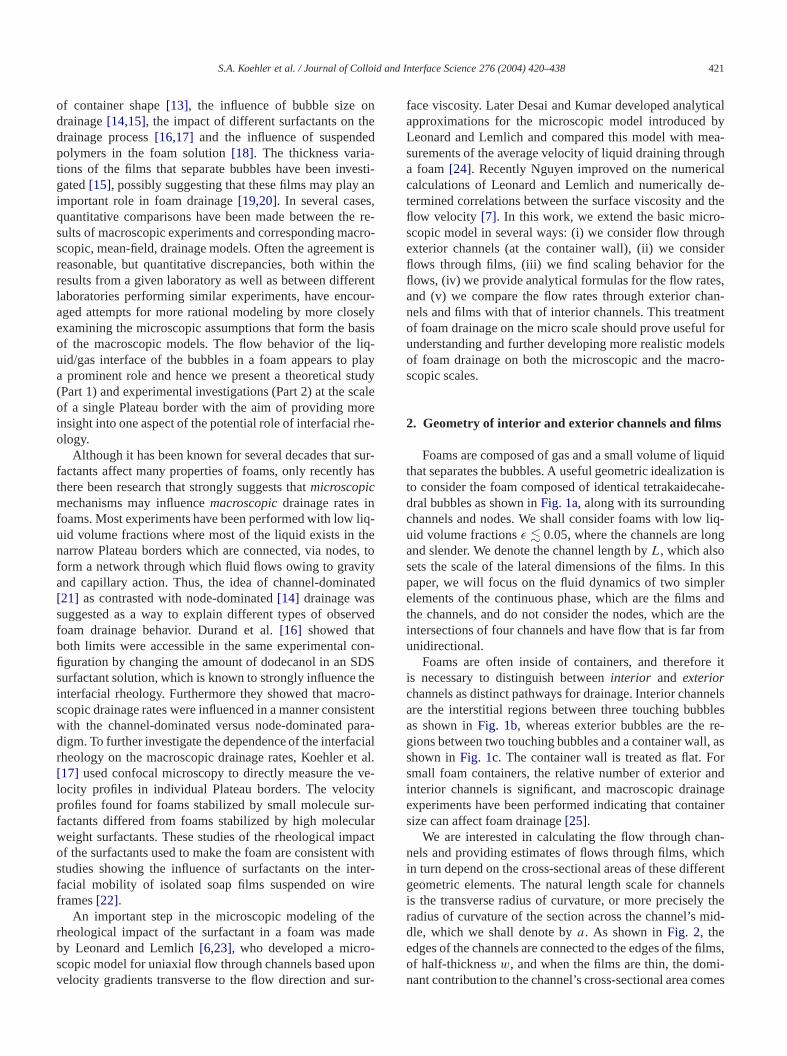
Foams are composed of gas and a small volume of liqthat separates the bubbles. A useful geometric idealizatito consider the foam composedof identical tetrakaidecahedral bubbles as shown inFig. 1a, along with its surroundingchannels and nodes. We shall consider foams with lowuid volume fractionsε � 0.05, where the channels are lonand slender. We denote the channel length byL, which alsosets the scale of the lateral dimensions of the films. Inpaper, we will focus on the fluid dynamics of two simpelements of the continuous phase, which are the filmsthe channels, and do not consider the nodes, which arintersections of four channels and have flow that is far frunidirectional.
Foams are often inside of containers, and thereforis necessary to distinguish betweeninterior and exteriorchannels as distinct pathways for drainage. Interior channeare the interstitial regions between three touching bubas shown inFig. 1b, whereas exterior bubbles are thegions between two touching bubbles and a container washown inFig. 1c. The container wall is treated as flat. Fsmall foam containers, the relative number of exteriorinterior channels is significant, and macroscopic drainagexperiments have been performed indicating that contasize can affect foam drainage[25].
We are interested in calculating the flow through chnels and providing estimates of flows through films, whin turn depend on the cross-sectional areas of these diffegeometric elements. The natural length scale for chanis the transverse radius of curvature, or more preciselyradius of curvature of the section across the channel’s mdle, which we shall denote bya. As shown inFig. 2, theedges of the channels are connected to the edges of theof half-thicknessw, and when the films are thin, the domnant contribution to the channel’s cross-sectional area co
422 S.A. Koehler et al. / Journal of Colloid and Interface Science 276 (2004) 420–438
sboringthe
s
Fig. 1. (a) Drawing of a tetrakaidecahedral cell, an idealized bubble in a foam with liquid volume fractionε = 0.005 (courtesy of A. Kraynik). The bubble ha14 films, 12 nodes and 36 channels that have lengthL. (b) Sketch of an interior channel (solid lines), which is the interstitial space between three neighbubbles and has radius of curvaturea. The dotted lines indicate the three films separating the three bubbles. (c) Sketch of an exterior channel, which isinterstitial space between two neighboring bubbles and the container wall.The dotted line indicates the film, and the dashed line with dots indicatethecontainer wall.
aryni-s.
nneofg-
ugh
un-s ofor
-
ereown-erio
ol-d,
an
uid
ealid
s isriorich-f the
thes. The
thelichions
n-very
ofidel’sheol-sity,
from a. We assume that the film thickness does not vmuch, due to capillary forces within the film that tend to uformly distribute liquid and remove curvature on the filmThe half-width of the film is denoted byH (w � H ), whichdepends on the number of sides of the film and the chalengthL. For example a hexagonal film has a full-widthabout 2H ≈ 2
√3L, depending on the orientation for a re
ular hexagonal face, whereas for a square face 2H ≈ L. Forthe purposes of providing upper bounds on the flow throthin films the approximationH ≈ L is adequate.
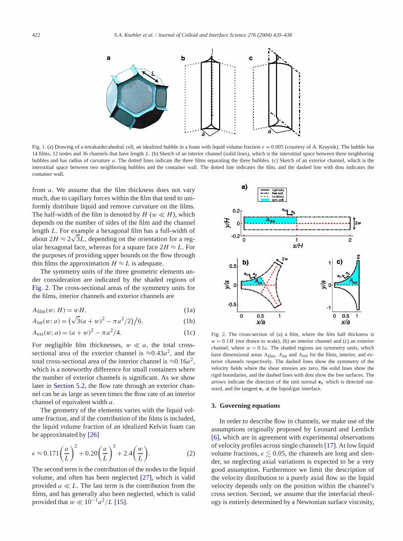
The symmetry units of the three geometric elementsder consideration are indicated by the shaded regionFig. 2. The cross-sectional areas of the symmetry unitsthe films, interior channels and exterior channels are
(1a)Afilm(w;H) = wH,
(1b)Aint(w;a) = (√3(a + w)2 − πa2/2
)/6,
(1c)Aext(w;a) = (a + w)2 − πa2/4.
For negligible film thicknesses,w � a, the total crosssectional area of the exterior channel is≈0.43a2, and thetotal cross-sectional area of the interior channel is≈0.16a2,which is a noteworthy difference for small containers whthe number of exterior channels is significant. As we shlater inSection 5.2, the flow rate through an exterior chanel can be as large as seven times the flow rate of an intchannel of equivalent widtha.
The geometry of the elements varies with the liquid vume fraction, and if the contribution of the films is includethe liquid volume fraction of an idealized Kelvin foam cbe approximated by[26]
(2)ε ≈ 0.171
(a
L
)2
+ 0.20
(a
L
)3
+ 2.4
(w
L
).
The second term is the contribution of the nodes to the liqvolume, and often has been neglected[27], which is validprovideda � L. The last term is the contribution from thfilms, and has generally also been neglected, which is vprovided thatw � 10−1a2/L [15].
l
f
r
Fig. 2. The cross-section of (a) a film, where the film half thicknesw = 0.1H (not drawn to scale), (b) an interior channel and (c) an extechannel, wherew = 0.1a. The shaded regions are symmetry units, whhave dimensional areasAfilm , Aint andAext for the films, interior, and exterior channels respectively. The dashed lines show the symmetry ovelocity fields where the shear stresses are zero, the solid lines showrigid boundaries, and the dashed lines with dots show the free surfacearrows indicate the direction of the unit normalen which is directed out-ward, and the tangentes at the liquid/gas interface.
3. Governing equations
In order to describe flow in channels, we make use ofassumptions originally proposed by Leonard and Lem[6], which are in agreement with experimental observatof velocity profiles across single channels[17]. At low liquidvolume fractions,ε � 0.05, the channels are long and sleder, so neglecting axial variations is expected to be agood assumption. Furthermore we limit the descriptionthe velocity distribution to a purely axial flow so the liquvelocity depends only on the position within the channcross section. Second, we assume that the interfacial rogy is entirely determined by a Newtonian surface visco
S.A. Koehler et al. / Journal of Colloid and Interface Science 276 (2004) 420–438 423
e tos.ere
ua-
nal
the,
gnif-ndelso
x-sian
s toels
sd atoutashe
per-sson,heroxi-
lds
h
l
e-ightas-
teaud in
cial
-ary
theto a
-ters
o
-
li-
wnng
mso-llyflow.
and neglect other effects such as Marangoni forces duvariations in the surfactant concentration at the interfaceThird, we assume that the velocity is close to zero whthe channel merges into the film[28]. Finally, we assumethat the flow is viscously dominated so that Stokes eqtions can be used. We align thez-axis with the directionof the flow, and denote the angle to the vertical byθ , with0 � θ � π/2. Because the flow is essentially unidirectiothrough the channels, the axial (scalar) velocityu inside thePlateau border is related to the driving force,G, by
(3)µ∇2u + G = 0 whereG = −∂p/∂z + ρg cosθ,
wherep is the liquid pressure,µ is the bulk viscosity andρg
is the gravitational force per unit volume. The choice fordirection of thez axis is axially along the direction of flowwith the z axis pointing downward at an angle ofθ to thevertical. Since the cross-sectional area does not vary siicantly in the flow direction, capillary forces, which depeon the curvature of the liquid/gas interface, are negligibland we can assume that the driving force for the flow is anot changing significantly withz.
In Fig. 2 the cross-sections of a film, interior and eterior channels are drawn using a dimensionless Cartecoordinate system. We defer the treatment of the filmAppendix A, and focus on the interior and exterior channdrawn inFigs. 2b and 2c. The shaded regions ofFigs. 2b and2c (also reproduced inFigs. 5 and 9) are the symmetry unitof the interior and exterior channels, with the origin placethe corner to the left. The velocity fields are symmetric abthe dashed lines, so the shearing stresses along the dlines are zero. The characteristic length scale isa, and thecharacteristic velocity scale isUchannel≡ a2G/µ. Quantitiesrescaled by the channel’s radius of curvature carry the suscript˜, for example the film’s dimensionless half-thickneis w = w/a. Thus we need to solve Poisson’s equati∇2u = −1, which requires numerical treatment owing to tunusual geometries; however we present analytical appmations inSection 4.
To describe the boundary conditions on the velocity fiewe define the normal and tangent vectors,en andes respec-tively, to a surface given byy = h(x) (seeFig. 2),
en = 1√1+ h′2
(ey − h′ex) and
(4)es = 1√1+ h′2
(ex + h′ey),
where primes denote differentiation with respect tox.For the symmetry unit of the interior channel, seeFig. 2b,
the bottom boundary is aty = 0, and the top boundary, whicconsists of a left and a right region, is at
y = hint(x; w) where
(5)hint(x; w) =
(1+ w) − √1− x2 for 0 � x � 1/2,
(1+ w) − √3x √
for 1/2� x � (1+ w)/ 3.
d
The boundary conditions on the flowfor the interior channeare[29]
(6a)∂u
∂y= 0 at y = 0, for 0 � x � (1+ w)/
√3,
(6b)∂u
∂n= 0 at y = 1+ w − √
3x,
(6c)u = 0 at x = 0, for 0 � y � w,(∂
∂s
)2
us = M∂u
∂nat y = hint(x; w), for 0 � x � 1/2,
where
(6d)M ≡ µa
µs.
The surface velocity is explicitly denoted asus(x) ≡u(x, hint(x; w)). The first two conditions indicate symmtry of the flow across the boundaries on the bottom and rside, respectively. The third boundary condition is thesumption that the velocity is zero at the edge of the Plaborder, where the film is connected, and will be discussemore detail below. The last condition(6c)is the coupling be-tween surface and bulk layer, which is set by the interfamobility M [30].
For the exterior channel,Fig. 2c, the boundaries are similar to those of the interior channel, and the top boundis
y = hext(x; w) where
(7)hext(x; w) ={
(1+ w) − √1− x2 for 0� x < 1,
(1+ w) for 1� x � 1+ w.
Also the Neumann (zero stress) boundary condition atright that is used for interior channels has been changedDirichlet (zero velocity) boundary condition
(8)u = 0 at x = 1+ w,
and the boundary at the top supports no stress,
(9)∂u
∂y= 0 at y = 1+ w.
Aside from the driving force,G, the dynamics for both interior and exterior channels depend on the four paramewith dimensionsµs,µ,w,a, which can be combined inttwo dimensionless parametersM and w. We show belowthat these two dimensionless parameters can further be combined into a single composite parameter,Λ, that describesthe dynamics.
A description of the flow in the films is far more compcated. Unlike results for channels[17] which show that theflow is essentially unidirectional, experiments have shothat for films there is substantial circulation. The flow alothe edges of films is typically upwards, which isoppositeto the flow in the channels and the middle of the filwhere the direction of the flow is downward. These mtions are likely due to Marangoni forces which generaproduce surface pressure gradients that oppose the
424 S.A. Koehler et al. / Journal of Colloid and Interface Science 276 (2004) 420–438
usedw
riosim-er
perro-
n-n in
all-he-earrtedionrica
o-thegason-he
forarefthism-
aidr-
becro-ragerfa-
ity oforni-er
thern thar-nels
geseeofve
For obtaining estimates we apply the same treatmentfor channels for a simplified model of unidirectional flothrough films neglecting Marangoni forces inAppendix A.Including Marangoni forces for a more realistic scenashould lead to an opposing secondary flow. Thus theplified model for films should prove useful for setting uppbounds on the flow through films, which in turn sets upbounds on the possible contribution of films to the macscopic drainage process.
4. Analytical and numerical results
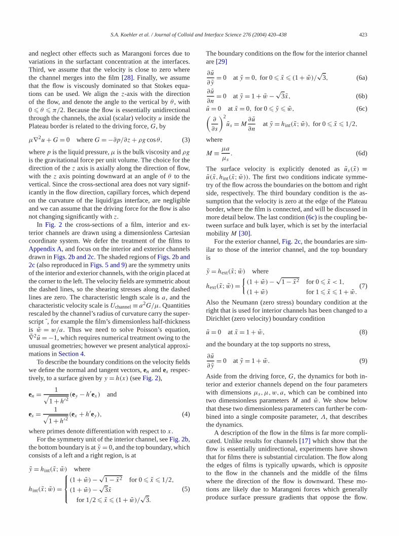
The original numerical computation of the flow field iside a Plateau border with the realistic shape showFig. 2b was performed by Leonard and Lemlich[6], whoused a finite-difference approach and fully implementedof the boundary conditions(6). Most importantly, the authors recognized the potential importance of interfacial rology, which they incorporated by accounting for the shviscosity of the surfactant layer. Nguyen recently reposimilar numerical work using improved numerical resolutand also presented several correlations that fit the numeresults [7]. In Appendix B we present a convenient prcedure applicable for thin surface films for convertingtop-most boundary condition at the interface with thephase,y = h(x), into a Neumann (zero stress) boundary cdition, while retaining the effect of interfacial shear in tsurfaces of the Plateau borders. This approach allowssuccessful simulations of the flow using standard softwpackages, such as MATLAB.Fig. 3 shows calculations othe velocity fields of interior and exterior channels usingprocedure. In the following, the numerical results are copared with asymptotic descriptions of the flow field thatin developing physical intuition for the ways in which suface mobility impacts the bulk flow.
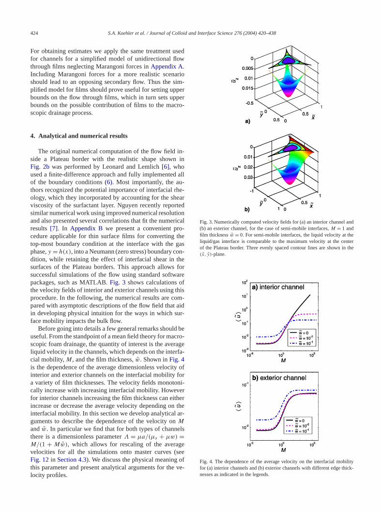
Before going into details a few general remarks shoulduseful. From the standpoint of a mean field theory for mascopic foam drainage, the quantity of interest is the aveliquid velocity in the channels, which depends on the intecial mobility, M, and the film thickness,w. Shown inFig. 4is the dependence of the average dimensionless velocinterior and exterior channels on the interfacial mobilitya variety of film thicknesses. The velocity fields monotocally increase with increasing interfacial mobility. Howevfor interior channels increasing the film thickness can eiincrease or decrease the average velocity depending ointerfacial mobility. In this section we develop analyticalguments to describe the dependence of the velocity oM
andw. In particular we find that for both types of channthere is a dimensionless parameterΛ = µa/(µs + µw) =M/(1 + Mw), which allows for rescaling of the averavelocities for all the simulations onto master curves (Fig. 12in Section 4.3). We discuss the physical meaningthis parameter and present analytical arguments for thelocity profiles.
l
f
e
-
Fig. 3. Numerically computed velocityfields for (a) an interior channel and(b) an exterior channel, for the case of semi-mobile interfaces,M = 1 andfilm thicknessw = 0. For semi-mobile interfaces, the liquid velocity at theliquid/gas interface is comparable tothe maximum velocity at the centerof the Plateau border. Three evenly spaced contour lines are shown in the(x, y)-plane.
Fig. 4. The dependence of the average velocity on the interfacial mobilityfor (a) interior channels and (b) exterior channels with different edge thick-nesses as indicated in the legends.

S.A. Koehler et al. / Journal of Colloid and Interface Science 276 (2004) 420–438 425
or-and
anpon
avi-ear
arisein-plyalo-inndn-
nte-aresal-rfacereconowfacele isre-ng
ing
ly-
ofdi-
dtface
as
dleft
left-
-
ed
ions
he
e
rittene
ofducte offacege,ve to
4.1. An integral method for establishing the variations insurface velocity
Although the detailed velocity fields of the Plateau bders require numerical calculation, certain quantitativequalitative features of the flow can be established usingelementary physical argument. This argument is based ua force balance for a control area, which involves the grtational force that drives the flow, and is opposed by shstresses along the periphery of the control area thatfrom both the rigid boundaries and the surfactant-ladenterfaces. The flow in channels is unidirectional, and we apthe force balance to interior and exterior channels. An angous treatment for the idealized thin film problem is givenAppendix A, which provides an estimate of the upper boufor the volumetric flow through the films due to gravitatioally driven drainage.
4.1.1. Asymptotic estimates for interior channelsConsider a control area for the cross section of an i
rior channel with a certain film thickness. Two examplesshown by the shaded regions ofFig. 5. Since the Reynoldnumber is small, the gravitational force on the fluid is banced by shear stresses (both from the bulk and the sufilm) which act at the periphery of the control area. Thare non-zero shear stresses only at the left edge of thetrol region, because of the symmetry condition on the flat the bottom and right sides, and at the curved interthe shearing of the fluid against the gas inside the bubbnegligible. Thus the “weight,” which is the area of shadedgion, Asupp(x; w), is supported by the shearing stress alothe left edge.
The area of the fluid inside the control area, extendfrom some value ofx to the edge on the right,x = (1 +w)/
√3, is
(10)Asupp(x; w) ≡(1+w)/
√3∫
x
hint(x′; w) dx ′.
The two-dimensional “weight” of this control area is entiresupported by shearing atx, which is the left side of the control region, and leads to the force balance
Asupp(x; w) =hint(x;w)∫y ′=0
(ex · ∇)u(x, y ′) dy ′
(11)+ M−1(ex · ∇)us(x) = 0,
where−ex is the unit normal at the left-hand boundarythe control surface pointing out of the control area, as incated by the arrow inFig. 5b. The first term on the right-hanside is the opposing force from shearing the bulk liquid ax,and the second term arises from shearing at the free sur(x, hint(x; w)).
The velocity field of the channel can be representedthe sum of the surface velocity,us , and an internal velocity
e
-
,
Fig. 5. Schematic diagrams of the control region for calculating the forcebalance on an interior channel, where the film thickness is zero. The shaderegion is Asupp, whose “weight” is supported by shearing at (a) the
edge,x = 0 (and soAsupp= Aint ), and (b) at the dashed line,x = 1/4.The arrow in (b) shows the orientation of the shearing plane at thehand boundary of the control area.
component,u1,
(12)u(x, y) = us (x) + u1(x, y),
where u1(x, hint(x; w)) = 0. For a completely rigid interface,M = 0, the surface velocity is zero andu1 is the fluidvelocity that solves(3).
A simple expression for the surface velocity is obtainby replacingu in (11)with (12),
du
dx=
(Asupp(x; w) −
hint(x;w)∫y ′=0
∂u1(x, y ′)∂x
dy ′)
(13)/(
hint(x; w) + M−1).The height of the channels is small,hint(x; w) � 1, be-cause the films are thin, and so the dominant variatof the internal velocity component are alongy, making alubrication-theory approach useful (seeSection 4.2). The in-ternal velocity component increases with increasingx, andneglecting it in(13)leads to an approximate equation for tvariations of the surface velocity that depends onM and theshape of the Plateau border:
(14)du
dx�
MAsupp(x; w)
1+ Mhint(x; w).
For small values ofx, a good approximation for the shapvariation is the parabolic profilehint(x; w) ≈ w + x2/2, andAsupp(x; w) ≈ Aint(w) [31].
ThenEq. (14)simplifies to
dus
dx� ΛAint(w)
(1+ Λx2/2)− wΛx +O(x)3 where
(15)Λ ≡ M
1+ Mw.
The dimensionless composite parameter can also be wasΛ = µa/(µs + µw), showing that this is a ratio of thproduct of the bulk viscosity and the characteristic sizethe channel to the combined surface viscosity and proof the bulk viscosity and the edge thickness. A large valuΛ corresponds to both small edge thickness and low surviscosity, so the velocity increases rapidly from the edbecause the shear stresses in the thin bulk region hasupport the “weight”Aint(w) (cf. Eq. (14)). A small value of
426 S.A. Koehler et al. / Journal of Colloid and Interface Science 276 (2004) 420–438
velytheting
di-lessnal
ci-ledi-neryforitys
nnel
ve-m-
loc-.t-ess.
th
l
ity
row.d-
zedtfa-
one-ry,n:e-ity
see
ity,
mher,l
ap-
oxi-ile,
-are
-
r
the
ows-
ofter-and
Λ corresponds to either a large surface viscosity or relatithick face, which in turn leads to a slower increase invelocity with increasing distance from the edge. Integrathe leading term fromEq. (15)with us(0) = 0 yields (herewe have not included the inequality)
(16)us(x)
Aint(w)≈ (2Λ)1/2 arctan(x
√Λ/2).
This result illustrates that the scale of variation of themensionless velocity as well as the maximum dimensionsurface velocity is set by the weight of the cross-sectioarea,Aint(w), and the single parameterΛ.
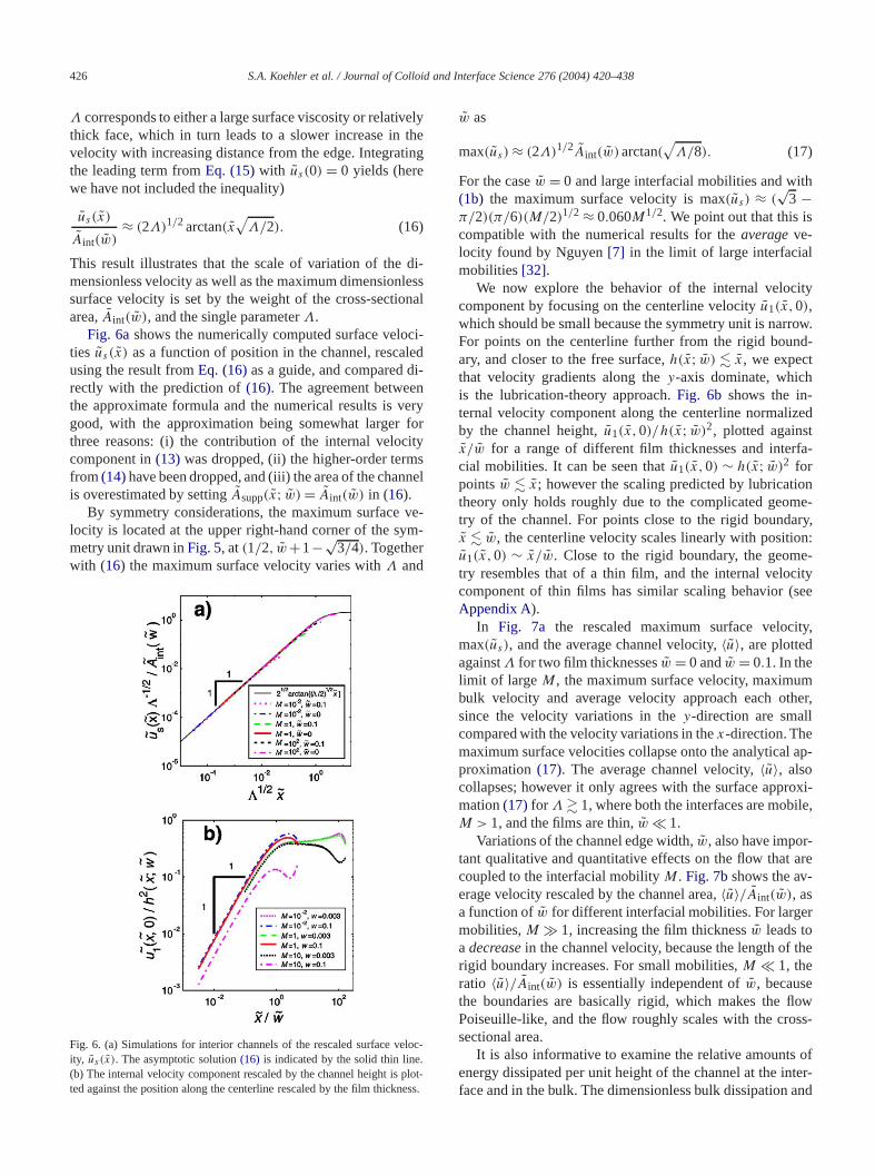
Fig. 6ashows the numerically computed surface veloties us (x) as a function of position in the channel, rescausing the result fromEq. (16)as a guide, and compared drectly with the prediction of(16). The agreement betweethe approximate formula and the numerical results is vgood, with the approximation being somewhat largerthree reasons: (i) the contribution of the internal veloccomponent in(13) was dropped, (ii) the higher-order termfrom(14)have been dropped, and (iii) the area of the chais overestimated by settingAsupp(x; w) = Aint(w) in (16).
By symmetry considerations, the maximum surfacelocity is located at the upper right-hand corner of the symetry unit drawn inFig. 5, at(1/2, w+1−√
3/4). Togetherwith (16) the maximum surface velocity varies withΛ and
Fig. 6. (a) Simulations for interior channels of the rescaled surface veity, us (x). The asymptotic solution(16) is indicated by the solid thin line(b) The internal velocity component rescaled by the channel height is ploted against the position along the centerline rescaled by the film thickn
w as
(17)max(us) ≈ (2Λ)1/2Aint(w)arctan(√
Λ/8).
For the casew = 0 and large interfacial mobilities and wi(1b) the maximum surface velocity is max(us) ≈ (
√3 −
π/2)(π/6)(M/2)1/2 ≈ 0.060M1/2. We point out that this iscompatible with the numerical results for theaverageve-locity found by Nguyen[7] in the limit of large interfaciamobilities[32].
We now explore the behavior of the internal veloccomponent by focusing on the centerline velocityu1(x,0),which should be small because the symmetry unit is narFor points on the centerline further from the rigid bounary, and closer to the free surface,h(x; w) � x, we expectthat velocity gradients along they-axis dominate, whichis the lubrication-theory approach.Fig. 6b shows the in-ternal velocity component along the centerline normaliby the channel height,u1(x,0)/h(x; w)2, plotted againsx/w for a range of different film thicknesses and intercial mobilities. It can be seen thatu1(x,0) ∼ h(x; w)2 forpointsw � x; however the scaling predicted by lubricatitheory only holds roughly due to the complicated geomtry of the channel. For points close to the rigid boundax � w, the centerline velocity scales linearly with positiou1(x,0) ∼ x/w. Close to the rigid boundary, the geomtry resembles that of a thin film, and the internal veloccomponent of thin films has similar scaling behavior (Appendix A).
In Fig. 7a the rescaled maximum surface velocmax(us), and the average channel velocity,〈u〉, are plottedagainstΛ for two film thicknessesw = 0 andw = 0.1. In thelimit of large M, the maximum surface velocity, maximubulk velocity and average velocity approach each otsince the velocity variations in they-direction are smalcompared with the velocity variations in thex-direction. Themaximum surface velocities collapse onto the analyticalproximation(17). The average channel velocity,〈u〉, alsocollapses; however it only agrees with the surface apprmation(17) for Λ � 1, where both the interfaces are mobM > 1, and the films are thin,w � 1.
Variations of the channel edge width,w, also have important qualitative and quantitative effects on the flow thatcoupled to the interfacial mobilityM. Fig. 7bshows the average velocity rescaled by the channel area,〈u〉/Aint(w), asa function ofw for different interfacial mobilities. For largemobilities,M � 1, increasing the film thicknessw leads toa decreasein the channel velocity, because the length ofrigid boundary increases. For small mobilities,M � 1, theratio 〈u〉/Aint(w) is essentially independent ofw, becausethe boundaries are basically rigid, which makes the flPoiseuille-like, and the flow roughly scales with the crossectional area.
It is also informative to examine the relative amountsenergy dissipated per unit height of the channel at the inface and in the bulk. The dimensionless bulk dissipation

S.A. Koehler et al. / Journal of Colloid and Interface Science 276 (2004) 420–438 427
i-
h,es,
pse
the
nif-ap
ithels.
esesate
atioce is
-te
ar-rean the
ve-
aring
ear-al tof
up-
n-
Fig. 7. (a) Simulations for the rescaled velocities plotted againstΛ. Theasymptotic solution(17) agrees well with the simulations for the maxmum surface velocity, max(us ). The average channel velocity,〈u〉, alsocollapses well using this scaling. (b) The effect of the channel edge widtw, on the average channel velocity for different interfacial mobilitiM = 10−2,1,102,104.
surface dissipation are, respectively,
(18a)Dbulk =∫ {(
∂u
∂x
)2
+(
∂u
∂y
)2}
dx dy,
(18b)Dsurf = M−1∫ (
∂us
∂s
)2
ds.
Fig. 8ashows that the surface dissipation results collaonto a universal curve as a function ofΛ for different filmthicknesses. The thin solid curve in the figure showsestimated dissipation calculated using(16), where velocityvariations along they-direction are neglected, and is
(19)Dsurf ≈{
2Λ2
8+ Λ+ Λ3/2
√2
arccot
(√8
Λ
)}Aint(w)2
M.
Agreement with thenumerical results[33] is good.Fig. 8bshows that for most values ofΛ the dissipation in the bulkdominates. Only for a certain range of values ofΛ � 1and w � 10−2 does the surface dissipation become sigicant[34], which is experimentally realized for certain sofoams (see Part 2).
4.1.2. Asymptotic estimates for exterior channelsFor exterior channels, a similar integral approach w
some modifications can be taken as for interior chann
Fig. 8. (a) Simulations of the rescaled power dissipated in the surfacplotted against the rescaled interfacial mobility for the film thicknesw = 0,10−3,10−2,10−1. The results are superimposed on the estim(19) which is indicated by the thin solid line. (b) The dependence of rof the power dissipated in the bulk to the power dissipated in the surfaplotted againstΛ.
The key difference between the interior and exterior channels is that the exterior channel hastwo rigid boundaries, ax = 0 and x = 1 + w, as compared with only one for thinterior channel; compareFigs. 2b and 2c. We consider the“weight” of a control area that is entirely supported by sheing at the left edge of the control area. This control aextends to the right and ends where the shear stress ix-direction is zero. The zero-stress line depends on thelocity field, which in turn depends onM andw, so we needthree parameters to describe the area supported by sheat x, which has “weight”Asupp(0;M,w).
We proceed by locating the positionxmax of the maxi-mum of the centerline velocity, which is where the shstress is zero (i.e.,(∂u/∂x)(xmax,0) = 0). Because the channels are slender, the component of the shear stress normthe line x = xmax should be close to zero. The “weight” othe supported region approximately is
(20)Asupp(x;M,w) ≈xmax∫x
hext(x′; w) dx ′,
and inFig. 9three examples of estimates for the region sported atx = 0 are shown with different choices of filmthicknesses and interfacial mobilities. Unlike interior cha
428 S.A. Koehler et al. / Journal of Colloid and Interface Science 276 (2004) 420–438
ed
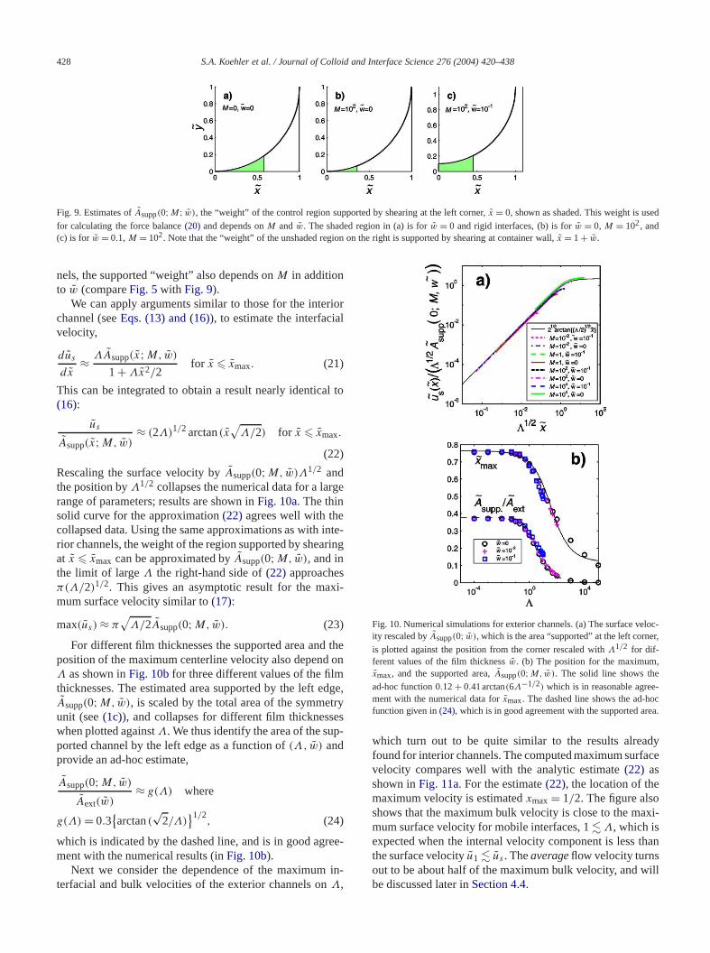
Fig. 9. Estimates ofAsupp(0;M; w), the “weight” of the control region supported by shearing at the left corner,x = 0, shown as shaded. This weight is usfor calculating the force balance(20) and depends onM andw. The shaded region in (a) is forw = 0 and rigid interfaces, (b) is forw = 0, M = 102, and(c) is for w = 0.1, M = 102. Note that the “weight” of the unshaded region on the right is supported by shearing at container wall,x = 1+ w.
riorl
l to
ge
inte-ring
xi-
theon
edgetryesp-
ree-
in-
loc-er,
,
-ocea.
dyace
xi-
than
ill
nels, the supported “weight” also depends onM in additionto w (compareFig. 5with Fig. 9).
We can apply arguments similar to those for the intechannel (seeEqs. (13) and (16)), to estimate the interfaciavelocity,
(21)dus
dx≈ ΛAsupp(x;M,w)
1+ Λx2/2for x � xmax.
This can be integrated to obtain a result nearly identica(16):
(22)
us
Asupp(x;M,w)≈ (2Λ)1/2 arctan(x
√Λ/2) for x � xmax.
Rescaling the surface velocity byAsupp(0;M,w)Λ1/2 andthe position byΛ1/2 collapses the numerical data for a larrange of parameters; results are shown inFig. 10a. The thinsolid curve for the approximation(22) agrees well with thecollapsed data. Using the same approximations as withrior channels, the weight of the region supported by sheaat x � xmax can be approximated byAsupp(0;M,w), and inthe limit of largeΛ the right-hand side of(22) approachesπ(Λ/2)1/2. This gives an asymptotic result for the mamum surface velocity similar to(17):
(23)max(us) ≈ π√
Λ/2Asupp(0;M,w).
For different film thicknesses the supported area andposition of the maximum centerline velocity also dependΛ as shown inFig. 10bfor three different values of the filmthicknesses. The estimated area supported by the leftAsupp(0;M,w), is scaled by the total area of the symmeunit (see(1c)), and collapses for different film thicknesswhen plotted againstΛ. We thus identify the area of the suported channel by the left edge as a function of(Λ, w) andprovide an ad-hoc estimate,
Asupp(0;M,w)
Aext(w)≈ g(Λ) where
(24)g(Λ) = 0.3{arctan(
√2/Λ)
}1/2,
which is indicated by the dashed line, and is in good agment with the numerical results (inFig. 10b).
Next we consider the dependence of the maximumterfacial and bulk velocities of the exterior channels onΛ,
,
Fig. 10. Numerical simulations for exterior channels. (a) The surface veity rescaled byAsupp(0; w), which is the area “supported” at the left corn
is plotted against the position from the corner rescaled withΛ1/2 for dif-ferent values of the film thicknessw. (b) The position for the maximumxmax, and the supported area,Asupp(0;M,w). The solid line shows thead-hoc function 0.12+ 0.41arctan(6Λ−1/2) which is in reasonable agreement with the numerical data forxmax. The dashed line shows the ad-hfunction given in(24), which is in good agreement with the supported ar
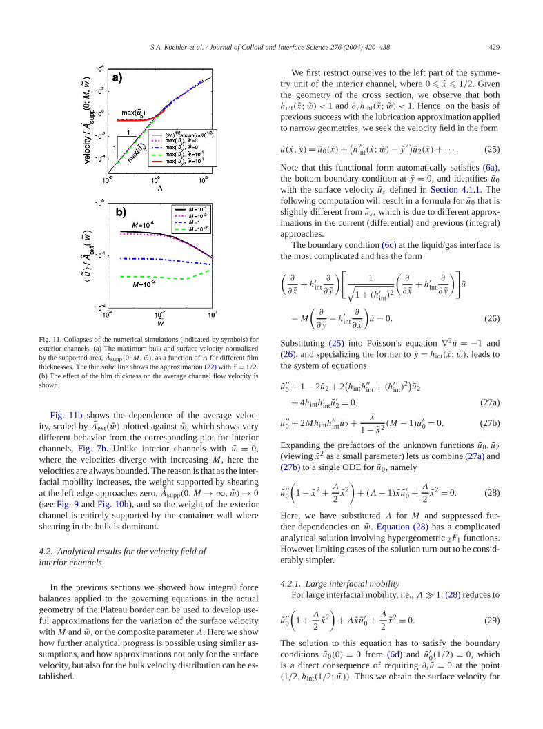
which turn out to be quite similar to the results alreafound for interior channels. The computed maximum surfvelocity compares well with the analytic estimate(22) asshown inFig. 11a. For the estimate(22), the location of themaximum velocity is estimatedxmax = 1/2. The figure alsoshows that the maximum bulk velocity is close to the mamum surface velocity for mobile interfaces, 1� Λ, which isexpected when the internal velocity component is lessthe surface velocityu1 � us . Theaverageflow velocity turnsout to be about half of the maximum bulk velocity, and wbe discussed later inSection 4.4.
S.A. Koehler et al. / Journal of Colloid and Interface Science 276 (2004) 420–438 429
rized
ty is
loc-
ior
interring
rere
rcetuauseity
as-aces-
e-
bothfliedrm
-al)
s
r-
id-
ary
or
Fig. 11. Collapses of the numerical simulations (indicated by symbols) foexterior channels. (a) The maximum bulk and surface velocity normalby the supported area,Asupp(0;M,w), as a function ofΛ for different filmthicknesses. The thin solid line shows the approximation(22)with x = 1/2.(b) The effect of the film thickness on the average channel flow velocishown.
Fig. 11b shows the dependence of the average veity, scaled byAext(w) plotted againstw, which shows verydifferent behavior from the corresponding plot for interchannels,Fig. 7b. Unlike interior channels withw = 0,where the velocities diverge with increasingM, here thevelocities are always bounded. The reason is that as thefacial mobility increases, the weight supported by sheaat the left edge approaches zero,Asupp(0,M → ∞, w) → 0(seeFig. 9 andFig. 10b), and so the weight of the exteriochannel is entirely supported by the container wall whshearing in the bulk is dominant.
4.2. Analytical results for the velocity field ofinterior channels
In the previous sections we showed how integral fobalances applied to the governing equations in the acgeometry of the Plateau border can be used to developful approximations for the variation of the surface velocwith M andw, or the composite parameterΛ. Here we showhow further analytical progress is possible using similarsumptions, and how approximations not only for the surfvelocity, but also for the bulk velocity distribution can be etablished.
-
l-
We first restrict ourselves to the left part of the symmtry unit of the interior channel, where 0� x � 1/2. Giventhe geometry of the cross section, we observe thathint(x; w) < 1 and∂xhint(x; w) < 1. Hence, on the basis oprevious success with the lubrication approximation appto narrow geometries, we seek the velocity field in the fo
(25)u(x, y) = u0(x) + (h2
int(x; w) − y2)u2(x) + · · · .Note that this functional form automatically satisfies(6a),the bottom boundary condition aty = 0, and identifiesu0
with the surface velocityus defined inSection 4.1.1. Thefollowing computation will result in a formula foru0 that isslightly different fromus , which is due to different approximations in the current (differential) and previous (integrapproaches.
The boundary condition(6c)at the liquid/gas interface ithe most complicated and has the form
(∂
∂x+ h′
int∂
∂y
)[1√
1+ (h′int)
2
(∂
∂x+ h′
int∂
∂y
)]u
(26)− M
(∂
∂y− h′
int∂
∂x
)u = 0.
Substituting(25) into Poisson’s equation∇2u = −1 and(26), and specializing the former toy = hint(x; w), leads tothe system of equations
u′′0 + 1− 2u2 + 2
(hinth
′′int + (h′
int)2)u2
(27a)+ 4hinth′intu
′2 = 0,
(27b)u′′0 + 2Mhinth
′′intu2 + x
1− x2(M − 1)u′
0 = 0.
Expanding the prefactors of the unknown functionsu0, u2(viewing x2 as a small parameter) lets us combine(27a)and(27b)to a single ODE foru0, namely
(28)u′′0
(1− x2 + Λ
2x2
)+ (Λ − 1)xu′
0 + Λ
2x2 = 0.
Here, we have substitutedΛ for M and suppressed futher dependencies onw. Equation (28)has a complicatedanalytical solution involving hypergeometric2F1 functions.However limiting cases of the solution turn out to be conserably simpler.
4.2.1. Large interfacial mobilityFor large interfacial mobility, i.e.,Λ � 1, (28)reduces to
(29)u′′0
(1+ Λ
2x2
)+ Λxu′
0 + Λ
2x2 = 0.
The solution to this equation has to satisfy the boundconditions u0(0) = 0 from (6d) and u′
0(1/2) = 0, whichis a direct consequence of requiring∂su = 0 at the point(1/2, hint(1/2; w)). Thus we obtain the surface velocity f
430 S.A. Koehler et al. / Journal of Colloid and Interface Science 276 (2004) 420–438
ma-
alleagees
me-
in
teace)
rate
is
e-the
fll-
-
eole
nderi-ns.thatnge
uldam
forlyti-;
mobile interfaces as
u(m)0 (x) = − x2
6− 1
3Λln2+ 1
3ln(2+ Λx2)
(30)+√
Λ
24√
2arctan
(√Λ
2x
)whereΛ � 1.
This recovers the salient behavior of the integral approxition (16), justifying the identification ofu0 andus .
Using(27a)and(27b), u2 can be calculated fromu0. ForlargeΛ, this is a very small contribution, and it stays smfor Λ � 1. In this regime,u(x, y) ≈ u0(x) is a reasonablapproximation for the flow field. Consequently, the avervelocity,〈u(m)〉, in the Plateau border with mobile interfacis simply obtained as
⟨u(m)
⟩ =1/2∫0
hint(x; w)u(m)0 dx
/ 1/2∫0
hint(x) dx
≈ {Λ5/2(3(−4+ √
3) + 2π)}−1
×{√
2
96(512− Λ3)arctan
(√Λ
8
)
+√
Λ
180
(−480+ 6Λ2 + 5Λ
(4+ ln4096
(31a)− 12Λ ln
(2+ Λ
4
)))}
≈ π
96√
2(12− 3√
3+ 2π)
√Λ
(31b)= 0.044443. . .√
Λ,
to the same order of approximation asu(m) itself [32]. With〈u(m)〉, we have also identified the (dimensionless) perability of the Plateau border at high mobility.
4.2.2. Small interfacial mobilityFor nearly rigid interfaces (Λ � 1), the full solution of
(28) can be expanded withΛ as a small parameter. Agarequiringu0(0) = 0 andu′
0(1/2) = 0, one obtains
u(r)0 (x) = Λ
48
(6x2 + (2π − 3
√3)arcsinx
(32)− 6(arcsinx)2),which vanishes linearly inΛ asΛ → 0. This contribution tou for smallΛ is generally negligible. It is interesting to nothat it agrees with a formal expansion of the mobile-interfresult(30)for smallΛ up to about 8% (maximum deviationthroughout the range of 0� x � 1/2. It is therefore hardlynecessary to define two different functions for an accudescription of the surface velocity.
As u(r)0 vanishes withΛ → 0, Eqs. (27)show that the
leading-order solution foru2 in the case of rigid interfacesu2 = 1/2, so that the velocity field in the left region is
(33)uleft(x, y) ≈ 1(h2
int(x; w) − y2) for x < 1/2.
2To continue this solution into the range 1/2 � x � (1+ w)/√3, we keep the requirement of parabolic profiles in they-
direction and assume that along the boundaryhint(x; w) (thediagonal between(1/2, hint(1/2; w)) and((1 + w)/
√3,0))
the velocity grows linearly from 0 touleft(1/2,0). We thushave
uright(x, y) ≈ 1
2h2
int(1/2; w)
×(
1−(
1+ w − √3x
1+ w − √3/2
)y2
h2int(x; w)
)(34)for x � 1/2.
Both (33) and(34) can be directly integrated over their rspective areas, giving rise to an average velocity forentire Plateau border with rigid interfaces
⟨u(r)
⟩ = 1
Aint(w)
( 1/2∫0
hint(x;w)∫0
uleft(x, y) dy dx
+(1+w)/
√3∫
1/2
hint(x;w)∫0
uright(x, y) dy dx
)
≈ {20(4
√3− 7)(π − 2
√3)2}−1
× {(1980
√3− 3449) + (5549
√3− 9540)π
+ 150(4√
3− 7)π2
+ ((2248
√3− 3886) + 8(1243
√3− 2148)π
+ 240(4√
3− 7)π2)w}(35)= 0.00352. . .+ 0.03303. . .w,
where we have included the leading-order influence ow.For smallw � 0.1, this approximation reproduces the smaΛ value of 〈u〉 quite well (cf. Fig. 12a). Because of thesmallness ofu0(x) for small Λ and of u2 for large Λ,adding(31a)and(35) yields an approximation for the average velocity in a Plateau border.Fig. 12ashows that thisapproximation〈u(m)〉 + 〈u(r)〉 is in good agreement with thfull numerics and the integral approximation over the whrange ofΛ.
4.3. Algebraic expressions for the drainage velocitiesof channels
We conclude this discussion of the flows in interior aexterior channels with a final comparison of the numcal simulations with analytical results and approximatioHaving algebraic expressions for the average velocityare in good agreement with the numerics over a large raof interfacial mobilities as well as film thicknesses shoprove helpful in developing and evaluating models for fodrainage.
For interior channels we have three approximationsthe average flow. Two approximations have been anacally found for small and largeΛ in the previous section
S.A. Koehler et al. / Journal of Colloid and Interface Science 276 (2004) 420–438 431
ehap-rom
i-
eh
-
c-
ss-site
the
o-
ns;n a
the
e
ree-heiorare
m-lm
t
e
the
lms
thed
ec-he
eti-rior
-
the
havethin
nagees.
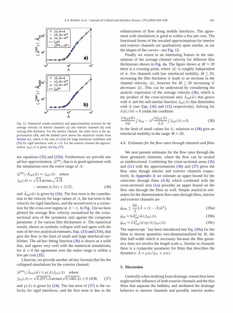
Fig. 12. Numerical results (symbols)and approximations (curves) for thaverage velocity of interior channels (a) and exterior channels (b) witvarying film thickness. For the interior channel, the solid curve is theproximation(36), and the dashed curve shows the analytical results fSection 4.2, which is the sum of(31a) for large interfacial mobilities and(35) for rigid interfaces withw = 0. For the exterior channel the approxmationfext(Λ) is given, seeEq. (37).
see equations(35) and(31b). Furthermore we provide onad-hoc approximation,〈uint〉, that is in good agreement witthe simulations over theentirerange ofΛ:
〈uint〉/Aint(w) ≈ fint(Λ) where
fint(Λ) = √2Λarctan
√Λ/8
(36)− arctan(Λ/2π) + 3/25,
andAint(w) is given by(1b). The first term is the contribution to the velocity for large values ofΛ, the last term is thevelocity for rigid interfaces, and the second term is a corretion for the cross-over regime atΛ ∼ 1. In Fig. 12awe haveplotted the average flow velocity normalized by the crosectional area of the symmetry unit against the compoparameterΛ for various film thicknessesw. The numericalresults, shown as symbols, collapse well and agree withsum of the two analytical estimates,Eqs. (35) and (31b), thatgive the flow in the limit of small and large interfacial mbilities. The ad-hoc fitting function(36) is drawn as a solidline, and agrees very well with the numerical simulatiofor w = 0 the agreement over the entire range is withifew per cent[35].
Likewise, we provide another ad-hoc formula that fitscollapsed simulations for the exterior channel:
〈uext〉/Aext(w) ≈ g(Λ)fext(Λ) where
(37)fext(Λ) = √0.2971Λarctan(
√0.1481Λ) + 0.1038,
andg(Λ) is given by(24). The last term of(37) is the ve-locity for rigid interfaces, and the first term is due to th
enhancement of flow along mobile interfaces. The agment with simulations is good to within a few per cent. Tfunctional forms of the rescaled approximations for interand exterior channels are qualitatively quite similar, asthe shapes of the curves—seeFig. 12.
Finally we return to an interesting feature in the siulations of the average channel velocity for different fithicknesses shown inFig. 4a. The figure shows atM ≈ 20there is a crossing point, where〈u〉 is roughly independenof w. For channels with low interfacial mobility,M � 20,increasing the film thicknessw leads to an increase in thchannel velocity,〈u〉, however forM � 20 increasingwdecreases〈u〉. This can be understood by consideringanalytic expression of the average velocity(36), which isthe product of the cross-sectional areaAint(w) that growswith w and the self-similar functionfint(Λ) that diminisheswith w (seeEqs. (1b) and (15)respectively). Solving for∂〈u〉/∂w = 0 yields the condition
(38)∂Aint(w)
∂w
/Aint − Λ2∂fint(Λ)
∂Λ
/fint(Λ) = 0.
In the limit of small values forw, solutions to(38) give aninterfacial mobility in the rangeM ≈ 20.
4.4. Estimates for the flow rates through channels and fi
We next present estimates for the flow rates throughthree geometric elements, where the flow can be treateas unidirectional. Combining the cross-sectional areas(1b)and (1c) with the approximations(36) and (37) gives theflow rates though interior and exterior channels resptively. In Appendix A we estimate an upper bound for tvelocities through films(A.8), which combined with thecross-sectional area(1a) provides an upper bound on thflow rate through the films as well. Simple analytical esmates for the dimensionless flow rates through films, inteand exterior channels are
(39a)qfilm � 4w
3
(Λ + (1− Λ)w2),
(39b)qint ≈ 6A2int(w)fint(Λ),
(39c)qext ≈ 2A2ext(w)g(Λ)fext(Λ).
The superscript has been introduced intoEq. (39a)for thefilms to denote quantitiesnon-dimensionalized byH , thefilm half-width which is necessary because the film geometry does not involve the length scalea. Similar to channelsthere is a composite parameter for films that describesdynamics:Λ = µw/(µs + µw).
5. Discussion
Generally when studying foam drainage, researchersneglected the influence of both exterior channels and thefilms that separate the bubbles, and attributed the draibehavior to interior channels and possibly interior nod

432 S.A. Koehler et al. / Journal of Colloid and Interface Science 276 (2004) 420–438
iore ests
entsed
atere-heior
nets anelsn-s oncesbletheter-imes
ctedm-Wectsrior
onf therea
me-
an-ch
per-d:ythat
re
siderbo-et
en-lfand
filmion-late
ythe
-
ge-
However liquid drains through both interior and exterchannels as well as films, making it is necessary to maktimates of the flow rate througheach of these three elemenindividually and then consider the number of these elemin a typical foam to estimate the net drainage rates. Armwith the results for flow through channels and an estimfor an upper bound on the flow through films from the pviousSection 4.4, we can investigate the importance of tflow through films and exterior channels relative to interchannels.
The relative importance of the three structures to thefoam drainage process depends on their relative numbertheir flow rates. The number of films and interior channare comparable[36], whereas the number of exterior chanels relative to the number of interior channels dependthe container geometry. For foams with immobile interfathe contribution to drainage due to the films is negligiunless the liquid content of the films is comparable toamount in the channels. On the other hand for rigid infaces, the flow through exterior channels is about seven tgreater than the flow through interior channels(39), so thedynamics of the drainage process can be strongly affewhen the amount of liquid in the exterior channels is coparable to the amount of liquid in the interior channels.also find that variations in the film width have small effeon the ratio of the flow through exterior channels and intechannels.
5.1. The contribution of films to foam drainage
The relative importance of flow through films dependsthe ratio of the cross-sectional areas and on the ratio ovelocities of the film to the channel. The cross-sectional aof the film is less than that of the channel at liquid volufractions(10w/a)2 � ε. For rigid interfaces the flow rate ratio is
qfilm
qint=
(200
3Aint(0)
)(Hw3
a4
)
(40)×{
1− 4√
3
Aint(0)
(w
a
)+O
(w
a
)2}
.
-
d
In general the film’s thickness is small compared to the chnel’s thickness, so the fluid velocity in the film is also musmaller. Keeping the leading term of(40) a condition fornegligible film flow is
(41)ε � (10w)6,
which generally is easily satisfied considering that the eximentally accessible liquid volume fractions are boundeε � 10−3 [37]. However with increasing interfacial mobilitthe flow through the films increases more rapidly thanthrough channels,〈ufilm〉 ∼ Λ versus〈uint〉 ∼ Λ1/2, makingit possible for film drainage to be important if the films asufficiently thick and the interfaces are sufficiently mobile.
To make these comparisons more concrete, we conthe situation an experimentalist is faced with in the laratory, in which typically the relationship between the ndrainage rate and the liquid volume fraction,ε, is of interest.Thus for the experimentalist a more natural choice of dimsionless parameters isε and a different form of the interfaciamobility parameterML ≡ µL/µs , which is independent oε and depends on other parameters: interfacial mobilitybubble size.
Experimental observations have shown that thethickness generally increases with liquid volume fract[23]. In the work by Carrier et al.[15] an approximate linear relationship between the film thickness,w, and channewidth, a, was found for a sodium dodecyl benzenesulfon(SDBS) foam with average channel lengthL ≈ 2.5 mm,which can be expressed as
(42)w/a � cf (a/L), with cf ≈ 10−2.
The experiments by Carrier suggest that the proportionalitfactor,cf , depends inversely on the channel length, i.e.,factor tends toincreasewith decreasingbubble size. No experimentally observed upper bound forcf exists, and howthe film thickness is set remains a mystery.
In Fig. 13we explore the relative importance of drainathrough films as a function ofε using the approximations(39) for the proportionality factorscf = 10−2,10−1,1and five interfacial mobilitiesML = 0,10−2,1,102,∞[38]. Comparing(42) with the criterion for negligible flow
e
Fig. 13. Estimates of an upper bound for the ratio of the flow rate through films relative to interior channels. Three different dimensionless film thickness ratioscf = 10−2,10−1,1, and the approximationH = L is used. Five different interfacial mobilities, expressed in terms ofML = µL/µs , are considered and thlegend is shown only in (c).
S.A. Koehler et al. / Journal of Colloid and Interface Science 276 (2004) 420–438 433
-
inedlm,
perms.neg-in,
,sam
ge
ages in-nr ofize.la-cts
al
anoss-nd o
lme
seior
wthe
ere
n-
on-.
arerhan-
-thege
ea
oflsratio
in-nels-
-rt bexte-ing
, andand
gh-For
through films with rigid interfaces(41)shows that contribution to the flow by films is negligible providedcf � 10−1
(see Fig. 13b). In the case of thick films, as shownFig. 13c, the drainage contribution due to films may indebe significant. The case where the amount of liquid in a fi∼4wH 2, exceeds that of a single channel,∼0.16a2L, is forcf � 10−1.
In summary, we have presented estimates for upbounds on the relative importance of drainage through filThese estimates show that drainage through films isligible for the cases when the films are sufficiently thw/a � 10−2(a/L) or equivalentlyw/H � ε provided thatfoam is not extremely dry,ε � 10−4. However for thickerfilms, i.e., w/H � ε, or very low liquid volume fractionsour estimates allow for the possibility that flow through filmmay indeed contribute in a more substantial way to the fodrainage process.
5.2. The contribution of exterior channels to foam draina
For foam in a container, the macroscopic foam drainprocess involves flow through exterior channels as well aterior channels. The number of exterior channels depends othe geometry of the foam container; the relative numbeexterior channels decreases with increasing container s
First we consider the flow rate of an exterior channel retive to an interior channel that is identical in all other respe(i.e., width, height, orientation, surfactant, etc.). Numericresults for the ratio of the flow rates as a function ofΛ areshown inFig. 14. As can be seen from(39b)and(39c)the ra-tio of the flow rate through an exterior channel relative tointerior channel scales with the square of the relative crsectional areas. The cross-sectional areas in turn depethe film thickness, and for immobile interfaces (Λ � 1), theratio of the flow rates decreases slightly with increasing fithickness:qext/qint ≈ 6.91−168w. Even if the interfaces armobile, for small values ofw � 10−2, the ratio of the flowrates does not deviate significantly from the casew = 0, seeFig. 14a. So in general it suffices to only consider the caw = 0 for comparing the flow rates of interior and exterchannels.
As the interfacial mobility increases, the liquid flothrough the interior channel increases more rapidly thanflow through the exterior channel. The crossing point whthe flows are comparable is atΛ ∼ 10, seeFig. 14a. Thus forvery mobile interfaces, it is unlikely that the exterior chanels play a large role in the foam drainage process.
Next we consider a cross-section of a foam inside a ctainer, withNext exterior channels andNint interior channelsFor example a foam inside a cylinder of radiusR roughly hasNext ∼ R/L exterior channels andNint ∼ ((R − L)/L)2 in-terior channels. In the case of cylindrical containers thatonly a few bubbles across,R � 4L, the number of exteriochannels can be comparable to the number of interior cnels[15]. Leaving out the contribution of the nodes, thetotal
n
Fig. 14. Ratio of the flow rates through exterior channels to interior channels. In (a) a dimensionless plot of the flow ratio is plotted againstcomposite parameterΛ. In (b) the film thickness is set to zero, and a ranof interfacial mobilitiesML is considered. The criterion onNext/Nint forequal flow through exterior and interior channels in a cross-sectional arof the foam is plotted againstε.
flow through this cross-section of the foam is
(43)Q = Nintqint + Nextqext.
For rigid interfaces, the flow rates through both typeschannels are equal when thenumber of internal channeis about seven times greater. In situations where theof the number of exterior to interior channels,Next/Nint, islarger than the curves drawn inFig. 14b, the total flow isdominated by the exterior channels. For foams with rigidterfaces inside a tube, the net flow through exterior chanis smaller provided that 6L � R, and as the interfacial mobility increases thiscondition relaxes.
Experiments by Brannigan and Bonfim[25] have shownthat at a given liquid volume fraction, the drainage rate increases with decreasing tube diameter, which may in paexplained by considering the increasing contribution of erior channels for small tubes. However a full understandof the drainage process requires the inclusion of nodesit may be necessary to even distinguish between exteriorinterior nodes.
6. Conclusions
In this work we used the concept of interfacial rheol-ogy to theoretically describe unidirectional flow throuthree geometric elements of foams: interior channels, exterior channels and the thin films separating the bubbles.channels this model has good experimental support[17], and
434 S.A. Koehler et al. / Journal of Colloid and Interface Science 276 (2004) 420–438
onld bytheandiorels,the
Onle to
am
oveth aica-s ofap-oapl-
geari-the
col-sitengthsite-
flowon-the
e
e-ws.iven-ng,sis.r-of-esfor
odelels,andrea
es,ur-ticityhesend-
y theu-
oreos-nts.y ofhasnd
in,eksPe-for
ien-
ofonian-
the
an-
enit.the
andthe
n-
ists
alsoler
for the thin films this model provides an upper boundthe flow. Our analytical results agree well with numericadata, and explain some of the numerical trends obtaineNguyen[7]. We have applied these models to elucidateimportance of drainage through the exterior channelsfilms relative to interior channels. If the number of exterchannels is comparable to the number of interior channthe foam drainage process may strongly be affected byexterior channels, depending on the interfacial mobility.the other hand, the number of films always is comparabthe number of channels, and if the films are thin,w � 10−2a,then they do not directly contribute appreciably to the fodrainage process.
The methods used to solve the flow fields should pruseful in other situations where there is an interface wisurface viscosity and the geometry is suitable for lubrtion theory approximations. For example our estimatethe upper bounds on the flow through thin films may beplicable to the flowing soap film experiment, where a sfilm is slowly flowing downward between two long paralel wires [39]. For films on the wire frame, there are larregions where the flow is unidirectional and there are no vations in the film geometry, whereas for films in foams,situation is more complex.
We have identified two composite parameters thatlapse the flow rates for films and channels. The compoparameters are a fraction composed of the relevant lescales for the geometric element: for films the compoparameter isΛ = w/(µs/µ + w) and for channels the composite parameter isΛ = a/(µs/µ+w). For the case of filmsin foams, our treatment provides an upper bound for theand therefore suggests that films cannot significantly ctribute to the drainage process in a direct way, unlessfilms are relatively thick,w/a � 10−2 and the interfaces arquite mobile,µa � µs .
The flow through nodes is far from unidirectional, bcause nodes are the convergence of four different floFor interior nodes the angle between the channels is gby Plateau’s rule: arccos(−1/3) ≈ 109◦. This makes determining the flow field through the nodes quite challengiespecially if surface viscosity is included in the analyTo date the details are poorly understood although ordemagnitude estimates from experiments[9] are in reasonablagreement with simulations[40]. Once simple expressionare available for the flow rates through the nodes, asthe channels and films, creating an effective-medium mfor foam drainage that takes into account exterior channinterior channels and nodes as well as film thicknessmaterial parameters such as surface viscosity should beizable.
Aside from calculating the flow through individual nodusing surface viscosity and aDirichlet boundary conditionfuture work may include a rigorous inclusion of other sfactant effects such as Marangoni stresses, Gibbs elasand adsorption and desorption kinetics. We believe that tsurfactant properties are responsible for the Dirichlet bou
l-
ary condition at the channel’s edges that are assumed btheory and are found in experimental situations. By simlating a region of foam containing several bubbles, a mrealistic calculation of flow through the films should be psible that exhibits circulation as observed in experimeOther new and interesting topics may also include a studthe mechanisms that set the film thickness, which alsointeresting implications for both diffusive coarsening arupture coarsening.
Acknowledgments
We thank V. Carrier, M. Durand, A. Kraynik, D. LangevM. Loewenberg, A. Saint-Jalmes, D. Weaire, and E. Wefor useful discussions. The Harvard MRSEC and thetroleum Research Fund (Grant 35926-AC9) are thankedtheir support, as is the Netherlands Organization for Sctific Research (NWO).
Appendix A. Upper bound estimates for films
In order to arrive at an estimate for an upper boundthe flow through films, we ignore the effects of Marangforces and treat the film in a similar fashion as the chnels described above inSection 4.1. We chooseH , whichis the half-width of the cross-section of the film, aslength scale, seeFig. 2a. We use the superscriptˆ to de-note quantities non-dimensionalized byH . The left and rightboundaries are atx = 0 and x = 1 respectively. The topand bottom boundaries are aty = 0 andy = w respectively,which simplifies the description of the unit normal and tgent vectors. The boundary conditions on the flow are
(A.1a)∂u
∂y= 0 aty = 0,
(A.1b)∂u
∂x= 0 atx = 1,
(A.1c)∂2u
∂x2= MH
∂u
∂yat y = w, with MH ≡ µH
µs
,
(A.1d)u = 0 at x = 0.
The first two conditions follow from the symmetry of thflow at the bottom and right edges of the symmetry uThe third condition is at the liquid/gas interface, wheresurfactant-laden interface has a surface viscosity,µs , and issheared by the bulk. The coupling between the surfacebulk layers is set by the dimensionless viscosity ratio ofsurface to the bulk,MH , which is the interfacial mobilityfor films. Recall that the film’s width scales with the chanel lengthH ∼ L, and soMH ∼ ML whereML = µL/µs isthe interfacial mobility parameter useful for experimentalwho can varyε andL (seeSection 5.1). The last conditionis the assumption that at the edge of the channel, whichis the edge of the film, the flow velocity is much smal

S.A. Koehler et al. / Journal of Colloid and Interface Science 276 (2004) 420–438 435
at
e-ssamerd
hegivet we
l-ingandnit
ich
und-
daryc-see-s
-
the
aceulk.
the
e
agell
ve-the
i-
m
-
ity,-
-
or-
and effectively zero. The two dimensionless parameters thdetermine the (unidirectional) flow through films arew andMH , which in turn depend on the four-dimensional paramtersµ,µs,H,w. We shall show that the two dimensionleparameters can be combined into a single composite parter that describes the flow in the films. It is straightforwato solve Poisson’s equation,∇2u = −1, with the boundaryconditions(A.1) exactly using Fourier series. However tFourier series solution is cumbersome, and does notas simple and intuitive results as the physical argumenpresent.
To describe the simplified flow in the thin films, we baance the gravitational force on the liquid with the resistviscous shear from both the surfactant-laden interfacethe bulk. The cross-section of the film’s symmetric uhas thicknessw and extentH as shown inFig. 2a. Let usconsider a control region inside this symmetry unit whextends through a range of positions fromx � x ′ � 1. The“weight” of this control region isAsupp= (1 − x)w, and issupported by shearing at the boundaries. Of the four boaries, only at the left boundary,x ′ = x, is there non-zeroshear: shearing of the liquid/gas interface at the top bounis negligible and the symmetry conditions of the fluid veloity on the right and bottom boundary impose zero shear—boundary conditions(A.1). Let us denote the surface velocity of the film, so the velocity in the film can be written athe sum of the surface velocity and bulk velocity (cf.(12)),
(A.2)u(x, y) = us(x) + u1(x, y),
whereu1(x, w) = 0. For a completely rigid interface,MH =0, the surface velocity is zero andu1 represents the bulk velocity of the fluid.
Balancing the supported weight of the film againsttotal shear across film atx gives the force balance
(A.3)Asupp= M−1H
dus(x)
dx+
w∫0
∂u1(x, y)
∂xdy + w
dus(x)
dx,
where the second term is the shearing force of the interfand the last two terms are the shearing force from the bNeglecting the third term in(A.3) yields
(A.4)dus(x)
dx� Λ(1− x) whereΛ = wMH
1+ wMH
.
The relationship between this composite parameter andcomposite parameter for the channels iswΛ = Λ. Theinequality arises from the fact thatu1 is monotonically in-creasing withx. Assuming that velocity variations in thy-direction are small, we can drop the inequality in(A.4)and use the rigid boundary at the left edge(A.1a)to arrive atan estimate for the interfacial velocity
(A.5)us (x) ≈ Λ
(x − 1
2x2
).
Fig. 15ashows that the numerical simulations of the avervelocity rescaled byΛ for films of different thicknesses acollapse, and agree well with the approximation(A.5).
-
,
Fig. 15. Numerical results for the surface velocity and the disturbancelocities. In (a) the simulated surface velocities are plotted on top ofapproximation(A.5) indicated by the thin solid line. In (b) the bulk velocties are plotted using the scaling suggested by the approximation(A.7).
We now estimate the correction to the velocity,u1, whichis due to variations in they-direction. Substituting(A.2) andthe approximation(A.5) into Poisson’s equation gives
(A.6)
(∂2
∂x2+ ∂2
∂y2
)u1 = −(1− Λ),
where the boundary conditions onu1 are identical to thosefor flow in symmetry unit withrigid boundaries:u1(0, y) =0, u1(x, w) = 0, ∂u1(1, y)/∂x = 0 and∂u1(x,0)/∂x = 0.In the spirit of lubrication theory, we expect that far frothe left wall,x � w, the variations inu1 are primarily alongthe y-direction. Thus using(A.6) and the top and bottomboundary conditions foru1 we arrive at
(A.7)u1(x, y) ≈ w2(1− Λ)(1− (y/w)2)/2 for x � w.
Close to the left edge, forx � w, the rigid boundary condition introduces anx-dependence onu1. In Fig. 15b weshow that the first-order correction to the centerline velocrescaled using(A.7), plotted againstx/w collapses the simulations for a wide range ofMH andw. Far from the wall(x � w) the rescaled correction to the centerline velocityis 1/2, which agrees with(A.7). Close to the wall we empirically find that re-scaling by(1 − Λ)−1/3x/w collapsesthe curves, and to first orderu1(x,0) ≈ (1 − Λ)2/3wx. Wemerely point out this scaling behavior for the first-order c
436 S.A. Koehler et al. / Journal of Colloid and Interface Science 276 (2004) 420–438
l
if-he
al
ine
walledndod
sur-face
isole-
ndtheis-
k
geloc-
ness
eloc-
de-to
kesth
er,rr at
,
in-ce
esaceiva-
theinon
ayer,ted
t allcat-citymit
onur-s
i.e.,
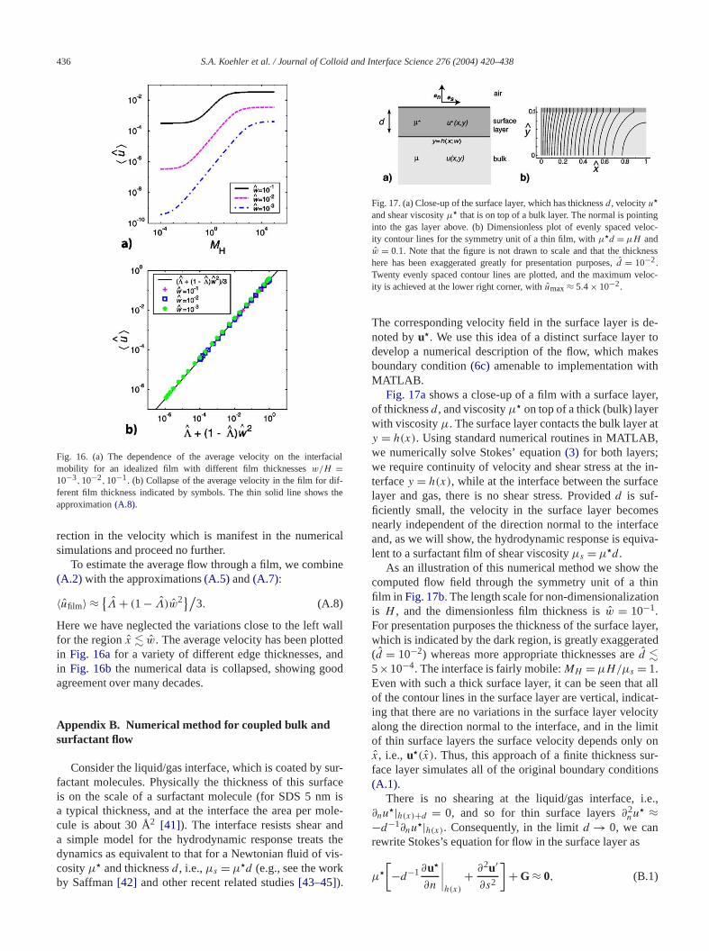
Fig. 16. (a) The dependence of the average velocity on the interfaciamobility for an idealized film with different film thicknessesw/H =10−3,10−2,10−1. (b) Collapse of the average velocity in the film for dferent film thickness indicated by symbols. The thin solid line shows tapproximation(A.8).
rection in the velocity which is manifest in the numericsimulations and proceed no further.
To estimate the average flow through a film, we comb(A.2) with the approximations(A.5) and(A.7):
(A.8)〈ufilm〉 ≈ {Λ + (1− Λ)w2}/3.
Here we have neglected the variations close to the leftfor the regionx � w. The average velocity has been plottin Fig. 16afor a variety of different edge thicknesses, ain Fig. 16bthe numerical data is collapsed, showing goagreement over many decades.
Appendix B. Numerical method for coupled bulk andsurfactant flow
Consider the liquid/gas interface, which is coated byfactant molecules. Physically the thickness of this suris on the scale of a surfactant molecule (for SDS 5 nma typical thickness, and at the interface the area per mcule is about 30 Å2 [41]). The interface resists shear aa simple model for the hydrodynamic response treatsdynamics as equivalent to that for a Newtonian fluid of vcosityµ� and thicknessd , i.e.,µs = µ�d (e.g., see the worby Saffman[42] and other recent related studies[43–45]).
Fig. 17. (a) Close-up of the surface layer, which has thicknessd , velocityu�
and shear viscosityµ� that is on top of a bulk layer. The normal is pointininto the gas layer above. (b) Dimensionless plot of evenly spaced vity contour lines for the symmetry unit of a thin film, withµ�d = µH andw = 0.1. Note that the figure is not drawn to scale and that the thickhere has been exaggerated greatly for presentation purposes,d = 10−2.Twenty evenly spaced contour lines are plotted, and the maximum vity is achieved at the lower right corner, withumax≈ 5.4× 10⁻².
The corresponding velocity field in the surface layer isnoted byu�. We use this idea of a distinct surface layerdevelop a numerical description of the flow, which maboundary condition(6c) amenable to implementation wiMATLAB.
Fig. 17ashows a close-up of a film with a surface layof thicknessd , and viscosityµ� on top of a thick (bulk) layewith viscosityµ. The surface layer contacts the bulk layey = h(x). Using standard numerical routines in MATLABwe numerically solve Stokes’ equation(3) for both layers;we require continuity of velocity and shear stress at theterfacey = h(x), while at the interface between the surfalayer and gas, there is no shear stress. Providedd is suf-ficiently small, the velocity in the surface layer becomnearly independent of the direction normal to the interfand, as we will show, the hydrodynamic response is equlent to a surfactant film of shear viscosityµs = µ�d .
As an illustration of this numerical method we showcomputed flow field through the symmetry unit of a thfilm in Fig. 17b. The length scale for non-dimensionalizatiis H , and the dimensionless film thickness isw = 10−1.For presentation purposes the thickness of the surface lwhich is indicated by the dark region, is greatly exaggera(d = 10−2) whereas more appropriate thicknesses ared �5×10⁻⁴. The interface is fairly mobile:MH = µH/µs = 1.Even with such a thick surface layer, it can be seen thaof the contour lines in the surface layer are vertical, indiing that there are no variations in the surface layer veloalong the direction normal to the interface, and in the liof thin surface layers the surface velocity depends onlyx, i.e., u�(x). Thus, this approach of a finite thickness sface layer simulates all of the original boundary condition(A.1).
There is no shearing at the liquid/gas interface,∂nu
�|h(x)+d = 0, and so for thin surface layers∂2nu� ≈
−d−1∂nu�|h(x). Consequently, in the limitd → 0, we can
rewrite Stokes’s equation for flow in the surface layer as
(B.1)µ�
[−d−1∂u�
∂n
∣∣∣∣ + ∂2u′
∂s2
]+ G ≈ 0,
h(x)
S.A. Koehler et al. / Journal of Colloid and Interface Science 276 (2004) 420–438 437
m,-gure
er-hear
loc-the
ce
t
us-
nons,
heeson-
Bters
otw
ndmo-theve-s.
ents
ss,
in-th–
-
102
–
002)
01)
hys.
00)
99)
4.7.66
,
s ofeterlmsters
6)
ir
.lvereell,
r 14
msocal
’s
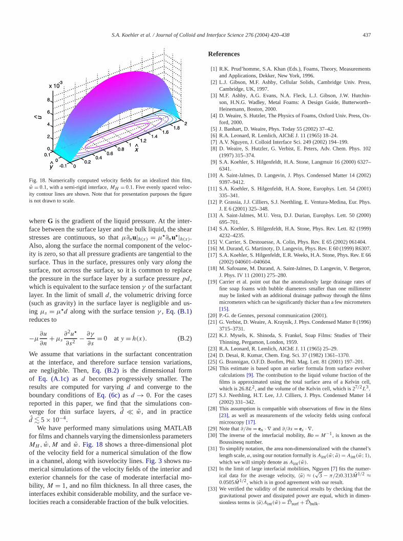
theen-
Fig. 18. Numerically computed velocity fields for an idealized thin filw = 0.1, with a semi-rigid interface,MH = 0.1. Five evenly spaced velocity contour lines are shown. Note that for presentation purposes the fiis not drawn to scale.
whereG is the gradient of the liquid pressure. At the intface between the surface layer and the bulk liquid, the sstresses are continuous, so thatµ∂nu|h(x) = µ�∂nu�|h(x).Also, along the surface the normal component of the veity is zero, so that all pressure gradients are tangential tosurface. Thus in the surface, pressures only varyalong thesurface, notacrossthe surface, so it is common to replathe pressure in the surface layer by a surface pressurepd ,which is equivalent to the surface tensionγ of the surfactanlayer. In the limit of smalld , the volumetric driving force(such as gravity) in the surface layer is negligible anding µs = µ�d along with the surface tensionγ , Eq. (B.1)reduces to
(B.2)−µ∂u
∂n+ µs
∂2u�
∂s2 − ∂γ
∂s= 0 aty = h(x).
We assume that variations in the surfactant concentratioat the interface, and therefore surface tension variatiare negligible. Then,Eq. (B.2) is the dimensional formof Eq. (A.1c) as d becomes progressively smaller. Tresults are computed for varyingd and converge to thboundary conditions ofEq. (6c)as d → 0. For the casereported in this paper, we find that the simulations cverge for thin surface layers,d � w, and in practiced � 5× 10⁻⁴.
We have performed many simulations using MATLAfor films and channels varying the dimensionless parameMH , w,M and w. Fig. 18 shows a three-dimensional plof the velocity field for a numerical simulation of the floin a channel, along with isovelocity lines.Fig. 3 shows nu-merical simulations of the velocity fields of the interior aexterior channels for the case of moderate interfacialbility, M = 1, and no film thickness. In all three cases,interfaces exhibit considerable mobility, and the surfacelocities reach a considerable fraction of the bulk velocitie
References
[1] R.K. Prud’homme, S.A. Khan (Eds.), Foams, Theory, Measuremand Applications, Dekker, New York, 1996.
[2] L.J. Gibson, M.F. Ashby, Cellular Solids, Cambridge Univ. PreCambridge, UK, 1997.
[3] M.F. Ashby, A.G. Evans, N.A. Fleck, L.J. Gibson, J.W. Hutchson, H.N.G. Wadley, Metal Foams: A Design Guide, ButterworHeinemann, Boston, 2000.
[4] D. Weaire, S. Hutzler, The Physics of Foams, Oxford Univ. Press, Oxford, 2000.
[5] J. Banhart, D. Weaire, Phys. Today 55 (2002) 37–42.[6] R.A. Leonard, R. Lemlich, AIChE J. 11 (1965) 18–24.[7] A.V. Nguyen, J. Colloid Interface Sci. 249 (2002) 194–199.[8] D. Weaire, S. Hutzler, G. Verbist, E. Peters, Adv. Chem. Phys.
(1997) 315–374.[9] S.A. Koehler, S. Hilgenfeldt, H.A. Stone, Langmuir 16 (2000) 6327
6341.[10] A. Saint-Jalmes, D. Langevin, J. Phys. Condensed Matter 14 (2
9397–9412.[11] S.A. Koehler, S. Hilgenfeldt, H.A. Stone, Europhys. Lett. 54 (20
335–341.[12] P. Grassia, J.J. Cilliers, S.J. Neethling, E. Ventura-Medina, Eur. P
J. E 6 (2001) 325–348.[13] A. Saint-Jalmes, M.U. Vera, D.J. Durian, Europhys. Lett. 50 (20
695–701.[14] S.A. Koehler, S. Hilgenfeldt, H.A. Stone, Phys. Rev. Lett. 82 (19
4232–4235.[15] V. Carrier, S. Destouesse, A. Colin, Phys. Rev. E 65 (2002) 06140[16] M. Durand, G. Martinoty, D. Langevin, Phys. Rev. E 60 (1999) R630[17] S.A. Koehler, S. Hilgenfeldt, E.R. Weeks, H.A. Stone, Phys. Rev. E
(2002) 040601–040604.[18] M. Safouane, M. Durand, A. Saint-Jalmes, D. Langevin, V. Bergeron
J. Phys. IV 11 (2001) 275–280.[19] Carrier et al. point out that the anomalously large drainage rate
fine soap foams with bubble diameters smaller than one millimmay be linked with an additional drainage pathway through the fimicrometers which can be significantly thicker than a few microme[15].
[20] P.-G. de Gennes, personal communication (2001).[21] G. Verbist, D. Weaire, A. Kraynik, J. Phys. Condensed Matter 8 (199
3715–3731.[22] K.J. Mysels, K. Shinoda, S. Frankel, Soap Films: Studies of The
Thinning, Pergamon, London, 1959.[23] R.A. Leonard, R. Lemlich, AIChE J. 11 (1965) 25–29.[24] D. Desai, R. Kumar, Chem. Eng. Sci. 37 (1982) 1361–1370.[25] G. Brannigan, O.F.D. Bonfim, Phil. Mag. Lett. 81 (2001) 197–201[26] This estimate is based upon an earlier formula from surface evo
calculations[9]. The contribution to the liquid volume fraction of thfilms is approximated using the total surface area of a Kelvin cwhich is 26.8L2, and the volume of the Kelvin cell, which is 27/2L3.
[27] S.J. Neethling, H.T. Lee, J.J. Cilliers, J. Phys. Condensed Matte(2002) 331–342.
[28] This assumption is compatible with observations of flow in the fil[23], as well as measurements of the velocity fields using confmicroscopy[17].
[29] Note that∂/∂n = en · ∇ and∂/∂s = es · ∇.[30] The inverse of the interfacial mobility,Bo = M−1, is known as the
Boussinesq number.[31] To simplify notation, the area non-dimensionalized with the channel
length scale,a, using our notation formally isAint(w; a) = Aint(w;1),which we will simply denote asAint(w).
[32] In the limit of large interfacial mobilities, Nguyen[7] fits the numer-ical data for the average velocity,〈u〉 ≈ (
√3 − π/2)0.313M1/2 ≈
0.0505M1/2, which is in good agreement with our result.[33] We verified the validity of the numerical results by checking that
gravitational power and dissipated power are equal, which in dimsionless terms is〈u〉Aint(w) = Dsurf + Dbulk.

438 S.A. Koehler et al. / Journal of Colloid and Interface Science 276 (2004) 420–438
amthe
ces,
achfilm
s, as
bub-
ld-
at-
256
)
397
[34] We had estimated the dissipation of liquid draining through the foin earlier work[9], but did not take into account the dissipation bychannel’s surface.
[35] A commonly used foam drainage model is based upon rigid interfawhere the average channel velocity in dimensionless units is〈u〉 ≈Aint/50 [8]. This in agreement with the algebraic estimate(36), andclose to the estimate in(35).
[36] Generally the most frequently occurring film has five sides, and einterior channel is shared by three films. So on average for eachthere are about 5/3 channels.
[37] In general the accessible experimental range of liquid volume fractionis 10−3 � ε � 0.3, so even for the case of highly mobile interfacesshown inFig. 13a, the liquid flow through the films is negligible.
[38] For the common surfactant sodium dodecyl sulfonate (SDS) and able size of about 1 mm,ML ∼ 10.
[39] M.A. Rutgers, X.-l. Wu, R. Bhagavatula, A.A. Petersen, W.I. Goburg, Phys. Fluids 8 (1996) 2847–2854.
[40] S.J. Cox, G. Bradley, S. Hutzler, D. Weaire, J. Phys. Condensed Mter 13 (2001) 4863–4869.
[41] D.O. Shah, N.F. Djabbarah, D.T. Wasan, Colloid Polym. Sci.(1978) 1002–1008.
[42] P.G. Saffman, J. Fluid Mech. 73 (1976) 593–602.[43] H.A. Stone, H.M. McConnell,Proc. R. Soc. London A 448 (1995
97–111.[44] H.A. Stone, A. Ajdari, J. Fluid Mech. 369 (1998) 151–173.[45] C. Barentin, C. Ybert, J.M. di Meglio, J.F. Joanny, J. Fluid Mech.
(1999) 331–345.