Embed Size (px)
Citation preview
JOINT SPECIFICATIONS, GUIDE & BIT SELECTION
FMT PRO Appendix I
55
Joint Specifications,Guide & Bit Selection
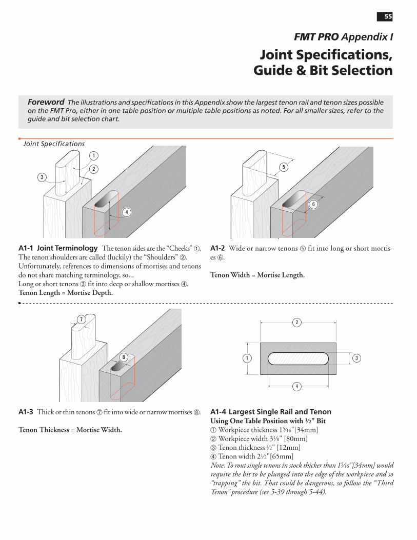
A1-1 Joint Terminology The tenon sides are the “Cheeks” ➀. The tenon shoulders are called (luckily) the “Shoulders” ➁.Unfortunately, references to dimensions of mortises and tenons do not share matching terminology, so...Long or short tenons ➂ fit into deep or shallow mortises ➃.Tenon Length = Mortise Depth.
1
2
3
4
A1-2 Wide or narrow tenons ➄ fit into long or short mortis-es ➅.
Tenon Width = Mortise Length.
6
5
A1-3 Thick or thin tenons ➆ fit into wide or narrow mortises ➇.
Tenon Thickness = Mortise Width.
7
8
A1-4 Largest Single Rail and TenonUsing One Table Position with 1⁄2" Bit➀ Workpiece thickness 15⁄16"[34mm]➁ Workpiece width 31⁄8" [80mm] ➂ Tenon thickness 1⁄2" [12mm]➃ Tenon width 21⁄2"[65mm]Note: To rout single tenons in stock thicker than 15⁄16"[34mm] would require the bit to be plunged into the edge of the workpiece and so “trapping” the bit. That could be dangerous, so follow the “Third Tenon” procedure (see 5-39 through 5-44).
2
4
1 3
Foreword The illustrations and specifications in this Appendix show the largest tenon rail and tenon sizes possible on the FMT Pro, either in one table position or multiple table positions as noted. For all smaller sizes, refer to the guide and bit selection chart.
Joint Specifications

Appendix I Frame Mortise & Tenon Jig User Guide JOINT SPECIFICATIONS, GUIDE & BIT SELECTION 56
A1-10 Thickest Mortise Board and Mortise Centers – Four table positionsThickness 3"[75mm] ➀.4 Mortises 1⁄2" x 2"[12 x 50mm] ➁.2 Mortises 1⁄2" x 41⁄2"[12 x 115mm] ➂.Spacing 9⁄16" to 1"[13 x 26mm] ➃.Board Width Clamping Capacity: 5"[128mm].
2
3
1
2
4
A1-5 Largest Single Rail and Tenon - Two Table Positions.Workpiece 1 5⁄16" x 51⁄2"[34 x 140mm] ➀.Tenon 1⁄2" x 41⁄2"*[12 x 115mm] ➁.Guide 1⁄2" x 21⁄2"[12 x 65mm].*Note: Using three table positions, tenon width ➂ may be up to 5"[125mm]
1
3
1 2
A1-6 Largest Tandem Double Tenon - Two Table Positions.Workpiece 1 5⁄16" x 51⁄2"[34 x 140mm] ➀.Tenons 1⁄2" x 2"[12 x 50mm] ➁.Guide 1⁄2" x 2"[12 x 50mm].
1
2
1 2
A1-7 Largest Side-by-Side Twin Tenon - Two* Table Positions.Workpiece 3" x 51⁄2"[76 x 140mm] ➀.Tenons 1⁄2" x 21⁄2+"[12 x 65+mm] ➁.Guide 1⁄2" x 21⁄2"[12 x 65mm].*Note: Add left-right table positions to the two front-back settings, for maximum workpiece and tenons extension. See A1-5
1
2
1
2
A1-8 Largest Quadruple Tenon - Four table positions.Workpiece 3" x 51⁄2"[76 x 140mm] ➀.Tenons 1⁄2" x 2"[12 x 50mm] ➁.Guide 1⁄2" x 2"[12 x 50mm].
1
2
1
2
A1-9 Largest Triple Tenon - Five* Table Positions.Workpiece 1 3⁄4 x 51⁄2"[44 x 140mm] ➀.Tenons 3⁄8" x 2"[10 x 50mm] ➁.Guide 3⁄8" x 2"[10 x 50mm].*Note: To avoid “trapping” the bit on larger workpieces it is necessary to rout the third tenon in three different FB table positions. See Chapter 5, Triple Joints.
1
22
1 22
57Appendix IFrame Mortise & Tenon Jig User GuideJOINT SPECIFICATIONS, GUIDE & BIT SELECTION
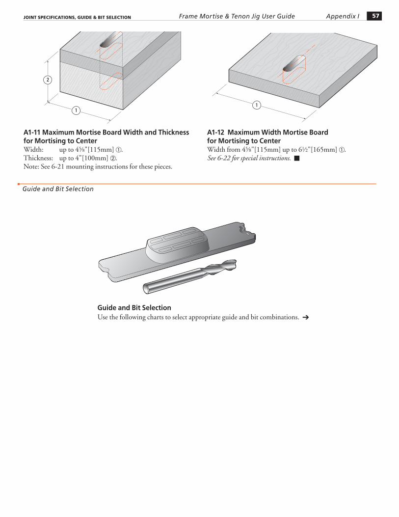
A1-11 Maximum Mortise Board Width and Thickness for Mortising to CenterWidth: up to 45⁄8"[115mm] ➀.Thickness: up to 4"[100mm] ➁.Note: See 6-21 mounting instructions for these pieces.
2
1
A1-12 Maximum Width Mortise Board for Mortising to CenterWidth from 45⁄8"[115mm] up to 61⁄2"[165mm] ➀.See 6-22 for special instructions. ■
Guide and Bit Selection
1
Guide and Bit SelectionUse the following charts to select appropriate guide and bit combinations. ➔
Appendix I Frame Mortise & Tenon Jig User Guide JOINT SPECIFICATIONS, GUIDE & BIT SELECTION 58
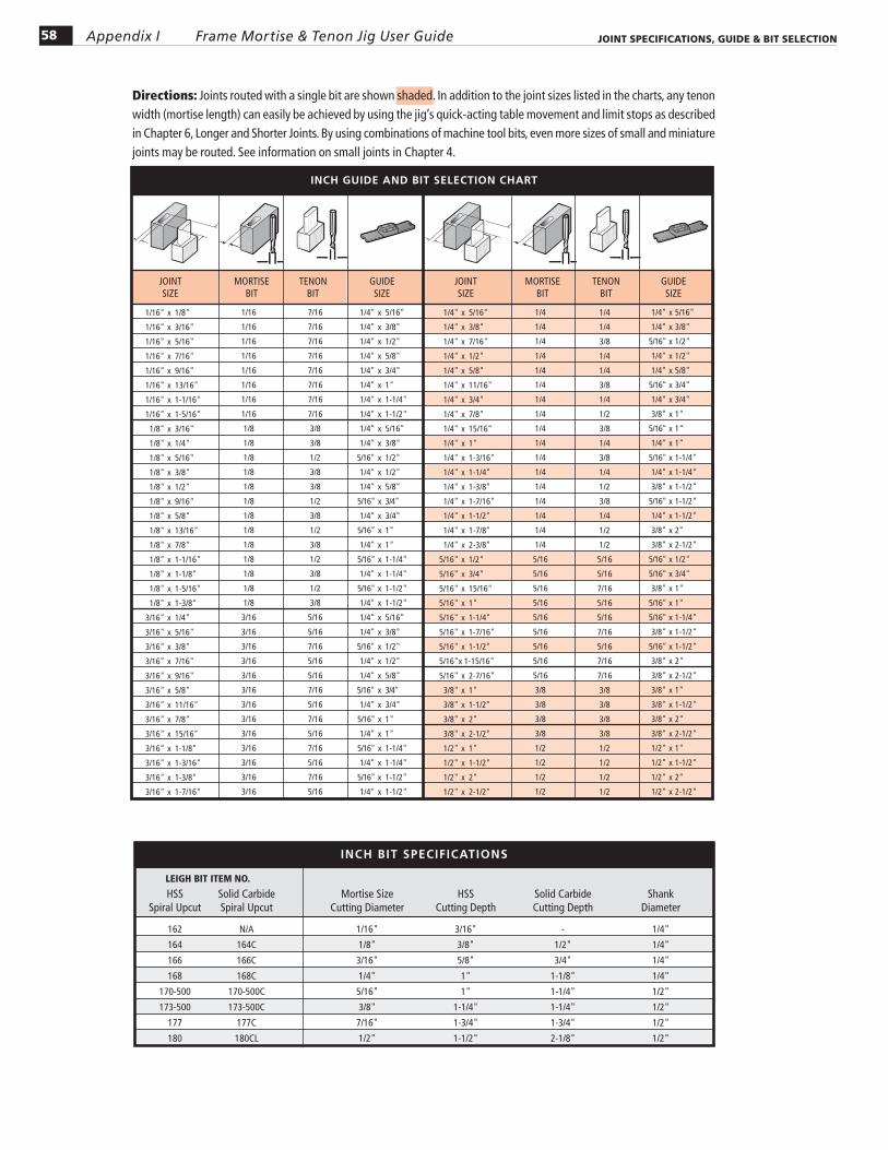
Directions: Joints routed with a single bit are shown shaded. In addition to the joint sizes listed in the charts, any tenon width (mortise length) can easily be achieved by using the jig’s quick-acting table movement and limit stops as described in Chapter 6, Longer and Shorter Joints. By using combinations of machine tool bits, even more sizes of small and miniature joints may be routed. See information on small joints in Chapter 4.
INCH GUIDE AND BIT SELECTION CHART
MORTISEBIT
MORTISEBIT
JOINTSIZE
JOINTSIZE
GUIDESIZE
GUIDESIZE
TENONBIT
TENONBIT
1/16" x 1/8"
1/16" x 3/16"
1/16" x 5/16"
1/16" x 7/16"
1/16" x 9/16"
1/16" x 13/16"
1/16" x 1-1/16"
1/16" x 1-5/16"
1/8" x 3/16"
1/8" x 1/4"
1/8" x 5/16"
1/8" x 3/8"
1/8" x 1/2"
1/8" x 9/16"
1/8" x 5/8"
1/8" x 13/16"
1/8" x 7/8"
1/8" x 1-1/16"
1/8" x 1-1/8"
1/8" x 1-5/16"
1/8" x 1-3/8"
3/16" x 1/4"
3/16" x 5/16"
3/16" x 3/8"
3/16" x 7/16"
3/16" x 9/16"
3/16" x 5/8"
3/16" x 11/16"
3/16" x 7/8"
3/16" x 15/16"
3/16" x 1-1/8"
3/16" x 1-3/16"
3/16" x 1-3/8"
3/16" x 1-7/16"
1/16
1/16
1/16
1/16
1/16
1/16
1/16
1/16
1/8
1/8
1/8
1/8
1/8
1/8
1/8
1/8
1/8
1/8
1/8
1/8
1/8
3/16
3/16
3/16
3/16
3/16
3/16
3/16
3/16
3/16
3/16
3/16
3/16
3/16
7/16
7/16
7/16
7/16
7/16
7/16
7/16
7/16
3/8
3/8
1/2
3/8
3/8
1/2
3/8
1/2
3/8
1/2
3/8
1/2
3/8
5/16
5/16
7/16
5/16
5/16
7/16
5/16
7/16
5/16
7/16
5/16
7/16
5/16
1/4" x 5/16"
1/4" x 3/8"
1/4" x 1/2"
1/4" x 5/8"
1/4" x 3/4"
1/4" x 1"
1/4" x 1-1/4"
1/4" x 1-1/2"
1/4" x 5/16"
1/4" x 3/8"
5/16" x 1/2"
1/4" x 1/2"
1/4" x 5/8"
5/16" x 3/4"
1/4" x 3/4"
5/16" x 1"
1/4" x 1"
5/16" x 1-1/4"
1/4" x 1-1/4"
5/16" x 1-1/2"
1/4" x 1-1/2"
1/4" x 5/16"
1/4" x 3/8"
5/16" x 1/2"
1/4" x 1/2"
1/4" x 5/8"
5/16" x 3/4"
1/4" x 3/4"
5/16" x 1"
1/4" x 1"
5/16" x 1-1/4"
1/4" x 1-1/4"
5/16" x 1-1/2"
1/4" x 1-1/2"
1/4" x 5/16"
1/4" x 3/8"
1/4" x 7/16"
1/4" x 1/2"
1/4" x 5/8"
1/4" x 11/16"
1/4" x 3/4"
1/4" x 7/8"
1/4" x 15/16"
1/4" x 1"
1/4" x 1-3/16"
1/4" x 1-1/4"
1/4" x 1-3/8"
1/4" x 1-7/16"
1/4" x 1-1/2"
1/4" x 1-7/8"
1/4" x 2-3/8"
5/16" x 1/2"
5/16" x 3/4"
5/16" x 15/16"
5/16" x 1"
5/16" x 1-1/4"
5/16" x 1-7/16"
5/16" x 1-1/2"
5/16" x 1-15/16"
5/16" x 2-7/16"
3/8" x 1"
3/8" x 1-1/2"
3/8" x 2"
3/8" x 2-1/2"
1/2" x 1"
1/2" x 1-1/2"
1/2" x 2"
1/2" x 2-1/2"
1/4
1/4
1/4
1/4
1/4
1/4
1/4
1/4
1/4
1/4
1/4
1/4
1/4
1/4
1/4
1/4
1/4
5/16
5/16
5/16
5/16
5/16
5/16
5/16
5/16
5/16
3/8
3/8
3/8
3/8
1/2
1/2
1/2
1/2
1/4
1/4
3/8
1/4
1/4
3/8
1/4
1/2
3/8
1/4
3/8
1/4
1/2
3/8
1/4
1/2
1/2
5/16
5/16
7/16
5/16
5/16
7/16
5/16
7/16
7/16
3/8
3/8
3/8
3/8
1/2
1/2
1/2
1/2
1/4" x 5/16"
1/4" x 3/8"
5/16" x 1/2"
1/4" x 1/2"
1/4" x 5/8"
5/16" x 3/4"
1/4" x 3/4"
3/8" x 1"
5/16" x 1"
1/4" x 1"
5/16" x 1-1/4"
1/4" x 1-1/4"
3/8" x 1-1/2"
5/16" x 1-1/2"
1/4" x 1-1/2"
3/8" x 2"
3/8" x 2-1/2"
5/16" x 1/2"
5/16" x 3/4"
3/8" x 1"
5/16" x 1"
5/16" x 1-1/4"
3/8" x 1-1/2"
5/16" x 1-1/2"
3/8" x 2"
3/8" x 2-1/2"
3/8" x 1"
3/8" x 1-1/2"
3/8" x 2"
3/8" x 2-1/2"
1/2" x 1"
1/2" x 1-1/2"
1/2" x 2"
1/2" x 2-1/2"
LEIGH BIT ITEM NO.
HSS Solid Carbide Mortise Size HSS Solid Carbide Shank Spiral Upcut Spiral Upcut Cutting Diameter Cutting Depth Cutting Depth Diameter
162 N/A 1/16" 3/16" - 1/4"
164 164C 1/8" 3/8" 1/2" 1/4"
166 166C 3/16" 5/8" 3/4" 1/4"
168 168C 1/4" 1" 1-1/8" 1/4"
170-500 170-500C 5/16" 1" 1-1/4" 1/2"
173-500 173-500C 3/8" 1-1/4" 1-1/4" 1/2"
177 177C 7/16" 1-3/4" 1-3/4" 1/2"
180 180CL 1/2" 1-1/2" 2-1/8" 1/2"
INCH BIT SPECIFICATIONS
59Appendix IFrame Mortise & Tenon Jig User GuideJOINT SPECIFICATIONS, GUIDE & BIT SELECTION
METRIC GUIDE AND BIT SELECTION CHART
6
6
6
6
6
6
6
6
6
6
6
6
6
6
7
7
7
7
7
7
8
8
8
8
8
8
8
8
8
8
8
10
10
10
10
10
12
12
12
12
12
2 x 4
2 x 6
2 x 11
2 x 16
2 x 21
2 x 26
2 x 31
2 x 36
3 x 5
3 x 7
3 x 12
3 x 17
3 x 22
3 x 27
3 x 32
3 x 37
4 x 6
4 x 8
4 x 11
4 x 13
4 x 16
4 x 18
4 x 21
4 x 23
4 x 26
4 x 28
4 x 31
4 x 33
4 x 36
4 x 38
5 x 7
5 x 9
5 x 14
5 x 19
5 x 24
5 x 29
5 x 34
5 x 39
2
2
2
2
2
2
2
2
3
3
3
3
3
3
3
3
4
4
4
4
4
4
4
4
4
4
4
4
4
4
5
5
5
5
5
5
5
5
10
10
10
10
10
10
10
10
9
9
9
9
9
9
9
9
8
8
12
8
12
8
12
8
12
8
12
8
12
8
7
7
7
7
7
7
7
7
6 x 8
6 x 10
6 x 15
6 x 20
6 x 25
6 x 30
6 x 35
6 x 40
6 x 8
6 x 10
6 x 15
6 x 20
6 x 25
6 x 30
6 x 35
6 x 40
6 x 8
6 x 10
8 x 15
6 x 15
8 x 20
6 x 20
8 x 25
6 x 25
8 x 30
6 x 30
8 x 35
6 x 35
8 x 40
6 x 40
6 x 8
6 x 10
6 x 15
6 x 20
6 x 25
6 x 30
6 x 35
6 x 40
6 x 8
6 x 10
6 x 13
6 x 15
6 x 18
6 x 20
6 x 23
6 x 25
6 x 28
6 x 30
6 x 33
6 x 35
6 x 38
6 x 40
7 x 14
7 x 19
7 x 24
7 x 29
7 x 34
7 x 39
8 x 15
8 x 20
8 x 23
8 x 25
8 x 30
8 x 33
8 x 35
8 x 40
8 x 43
8 x 53
8 x 63
10 x 25
10 x 35
10 x 45
10 x 55
10 x 65
12 x 25
12 x 35
12 x 45
12 x 55
12 x 65
6
6
10
6
10
6
10
6
10
6
10
6
10
6
9
9
9
9
9
9
8
8
12
8
8
12
8
8
12
12
12
10
10
10
10
10
12
12
12
12
12
6 x 8
6 x 10
8 x 15
6 x 15
8 x 20
6 x 20
8 x 25
6 x 25
8 x 30
6 x 30
8 x 35
6 x 35
8 x 40
6 x 40
8 x 15
8 x 20
8 x 25
8 x 30
8 x 35
8 x 40
8 x 15
8 x 20
10 x 25
8 x 25
8 x 30
10 x 35
8 x 35
8 x 40
10 x 45
10 x 55
10 x 65
10 x 25
10 x 35
10 x 45
10 x 55
10 x 65
12 x 25
12 x 35
12 x 45
12 x 55
12 x 65
GUIDESIZE
GUIDESIZE
JOINTSIZE
TENONBIT
TENONBIT
MORTISEBIT
MORTISEBIT
JOINTSIZE
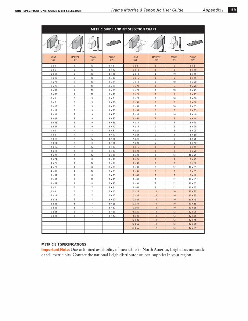
METRIC BIT SPECIFICATIONSImportant Note: Due to limited availability of metric bits in North America, Leigh does not stock or sell metric bits. Contact the national Leigh distributor or local supplier in your region.

Appendix I Frame Mortise & Tenon Jig User Guide JOINT SPECIFICATIONS, GUIDE & BIT SELECTION 60
JIG ADJUSTMENTS
FMT PRO Appendix II
61
Jig Adjustments
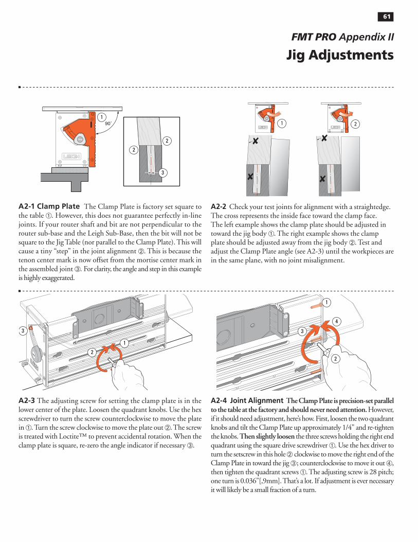
A2-1 Clamp Plate The Clamp Plate is factory set square to the table ➀. However, this does not guarantee perfectly in-line joints. If your router shaft and bit are not perpendicular to the router sub-base and the Leigh Sub-Base, then the bit will not be square to the Jig Table (nor parallel to the Clamp Plate). This will cause a tiny “step” in the joint alignment ➁. This is because the tenon center mark is now offset from the mortise center mark in the assembled joint ➂. For clarity, the angle and step in this example is highly exaggerated.
90˚
2
3
2
1
A2-2 Check your test joints for alignment with a straightedge. The cross represents the inside face toward the clamp face. The left example shows the clamp plate should be adjusted in toward the jig body ➀. The right example shows the clamp plate should be adjusted away from the jig body ➁. Test and adjust the Clamp Plate angle (see A2-3) until the workpieces are in the same plane, with no joint misalignment.
1 2
A2-3 The adjusting screw for setting the clamp plate is in the lower center of the plate. Loosen the quadrant knobs. Use the hex screwdriver to turn the screw counterclockwise to move the plate in ➀. Turn the screw clockwise to move the plate out ➁. The screw is treated with Loctite™ to prevent accidental rotation. When the clamp plate is square, re-zero the angle indicator if necessary ➂.
3
2
1
A2-4 Joint Alignment The Clamp Plate is precision-set parallel to the table at the factory and should never need attention. However, if it should need adjustment, here’s how. First, loosen the two quadrant knobs and tilt the Clamp Plate up approximately 1/4" and re-tighten the knobs. Then slightly loosen the three screws holding the right end quadrant using the square drive screwdriver ➀. Use the hex driver to turn the setscrew in this hole ➁ clockwise to move the right end of the Clamp Plate in toward the jig ➂; counterclockwise to move it out ➃, then tighten the quadrant screws ➀. The adjusting screw is 28 pitch; one turn is 0.036"[,9mm]. That’s a lot. If adjustment is ever necessary it will likely be a small fraction of a turn.
1
2
3
4
62 Appendix II Frame Mortise & Tenon Jig User Guide JIG ADJUSTMENTS
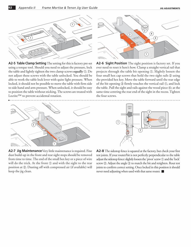
A2-5 Table Clamp Setting The setting for this is factory pre-set using a torque tool. Should you need to adjust the pressure, lock the table and lightly tighten the two clamp screws equally ➀. Do not adjust these screws with the table unlocked. You should be able to work the table lock lever with quite light pressure. When locked, it should not be possible to move the table with firm side to side hand and arm pressure. When unlocked, it should be easy to position the table without sticking. The screws are treated with Loctite™ to prevent accidental rotation.
1
1
A2-6 Sight Position The sight position is factory set. If you ever need to reset it here’s how. Clamp a straight vertical rail that projects through the table bit opening ➀. Slightly loosen the four small hex cap screws that hold the two sight rails ➁ using the provided hex key. Move the table forward until the rear edge of the bit opening ➂ firmly touches the vertical rail ➀, and lock the table. Pull the sight and rails against the wood piece ➃; at the same time centring the rear end of the sight in the recess. Tighten the four screws.
2
3
42
1
A2-7 Jig Maintenance Very little maintenance is required. Fine dust build-up in the front and rear sight stops should be removed from time to time. The end of the small hex key or a piece of wire will do the trick. At the front ➀ and with the sight to the rear position at ➁. Dusting off with compressed air (if available) will keep the jig clean.
1
2
A2-8 The sidestop fence is squared at the factory, but check your first test joints. If your router/bit is not perfectly perpendicular to the table adjust the sidestop fence: slightly loosen the 'pivot' screw ➀ and the 'lock' screw ➁. Adjust the angle ➂ to match the bit and retighten. Rout test joints to confirm correct setting. Once locked in this position it should never need adjusting when used with that same router. ■
1
2
3
3

CUSTOMER SUPPORT
FMT PRO Appendix III
63
FMT Pro Parts List
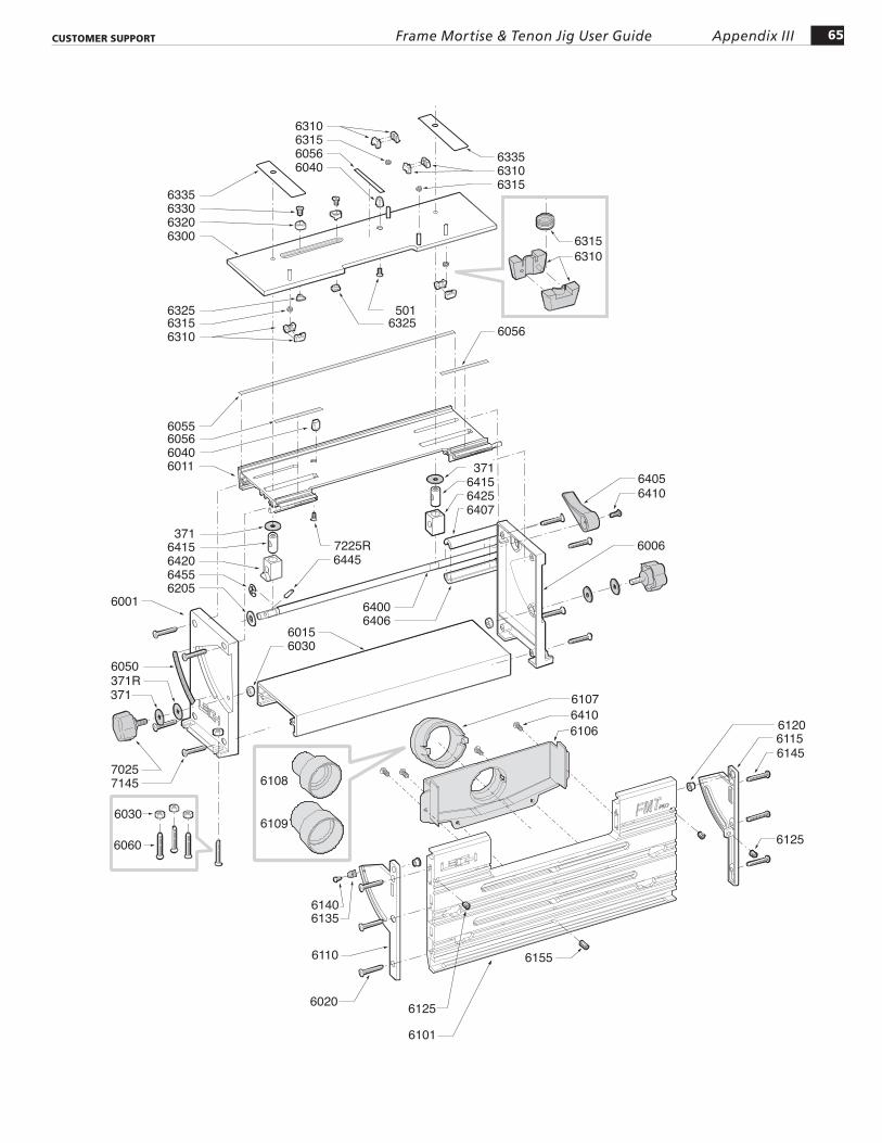
Foreword See the following pages for part drawings and part numbers. Please call Leigh to order parts.

64 Appendix III Frame Mortise & Tenon Jig User Guide CUSTOMER SUPPORT
QUANTITY PART NO. PER JIG PART DESCRIPTION
311 2 1/2" x 3" Compression Springs 371 4 1/4" x 7/8" x .031" Nylon Washers 371R 2 9/32" x 7/8" x .016" Nylon Washers 501 3 8-32 x 3/8" Square Socket No.2 Robertson
5100 2 Sub-Base Fence Rods 8.453" long, 7mm dia. 5130 2 M6x14mm Hex Socket Button Hd Cap Screws (for Festool) 6001 1 LH End Housing 6006 1 RH End Housing 6011 1 Top Extrusion 6015 1 Bottom Extrusion 6020 3 10 x 1-1/4" Self tapping No.2 Robertson Oval Hd Screws 6030 6 1/4 - 20 Hex Nuts (for Quadrant Knobs & Jig Hold-down) 6040 2 Limit Stop Posts 6050 1 Angle Indicator Decal 6055 1 UHMW Strip Long 6056 3 UHMW Strip Short 6060 4 1/4-20 x 1" Flat Hd Machine Screws (Jig Hold-down)
6101 1 Clamp Plate 6106 1 Vacuum Box 6107 1 Vacuum Box Swivel 6108 1 Vacuum Hose Adaptor – Small 6109 1 Vacuum Hose Adaptor – Large 6110 1 LH Quadrant 6115 1 RH Quadrant 6120 2 Quadrant Bushings 6125 3 Hex Socket Flat Point Set Screws 1/4-28 x 3/8" 6130 2 Outrigger Bars 6135 1 Quadrant Angle Indicator 6140 8 6-32 x 3/8" Hex Socket Button Hd Screws 6145 3 10 x 1-1/4" Self Tapping No.2 Robertson SQ Drive Pan Hd Screws 6155 5 Hex Socket Flat Point Set Screw 1/4-28 X 5/8" 6166A Side Stop Fence Assembly complete 6027 1 Washer - 3mm 6166 1 Side Stop Fence Body 6171 1 Side Stop Squaring Block 6191 1 T-Bolt 6199 2 Washers 6410 2 10-24 x 3/8" Hex Socket Button Hd Cap Screw 9530 1 Lever 6410 4 10-24 x 3/8" Hex Socket Button Hd Cap Screws (for attaching vacuum box) 6195 8 8-32 x 3/4" Flat Hd Machine Screws (for Outrigger & Low Shim Spacers) 6196 4 8-32 Hex Nuts (for Outriggers) 6200 2 Clamp T-Bolts 3/8"-16 6205 3 3/8" x 3/4" x .062" Nylon Flat Washers 6210 2 3/8-16 Clamp T-Bolt Brass nuts 6220 2 Clamp Arm 6225 2 Clamp Arm Heel Pads 6230 2 Clamp Arm Toe Pads 6235 2 Clamp Swivel Pads 6240 2 Clamp Lifters 6245 2 Clamp Lifter Springs 7025 2 Quadrant Knobs 7145 8 10 x 1-1/4" Self Tapping No.2 Robertson SQ Drive Pan Hd Screws 7225R 1 Top Extrusion Stop Post Screw 801-375 2 Cam-Action Speed Clamps 802-375 2 Speed Clamp Step Washers
65Appendix IIIFrame Mortise & Tenon Jig User GuideCUSTOMER SUPPORT
6109
6108
6001
371R371
6050
6415371
642064556205
60566055
60406011
63156325
6325501
6310 6056
63306335
63206300
63156310
60566040
633563106315
63156310
61156120
6125
614570257145
6030
6060
6140
6006
64056410
6135
6110
6020
60156030
64006406
7225R6445
64256415
371
6407
6125
6155
64106106
6107
6101

66 Appendix III Frame Mortise & Tenon Jig User Guide CUSTOMER SUPPORT
QUANTITY PART NO. PER JIG PART DESCRIPTION
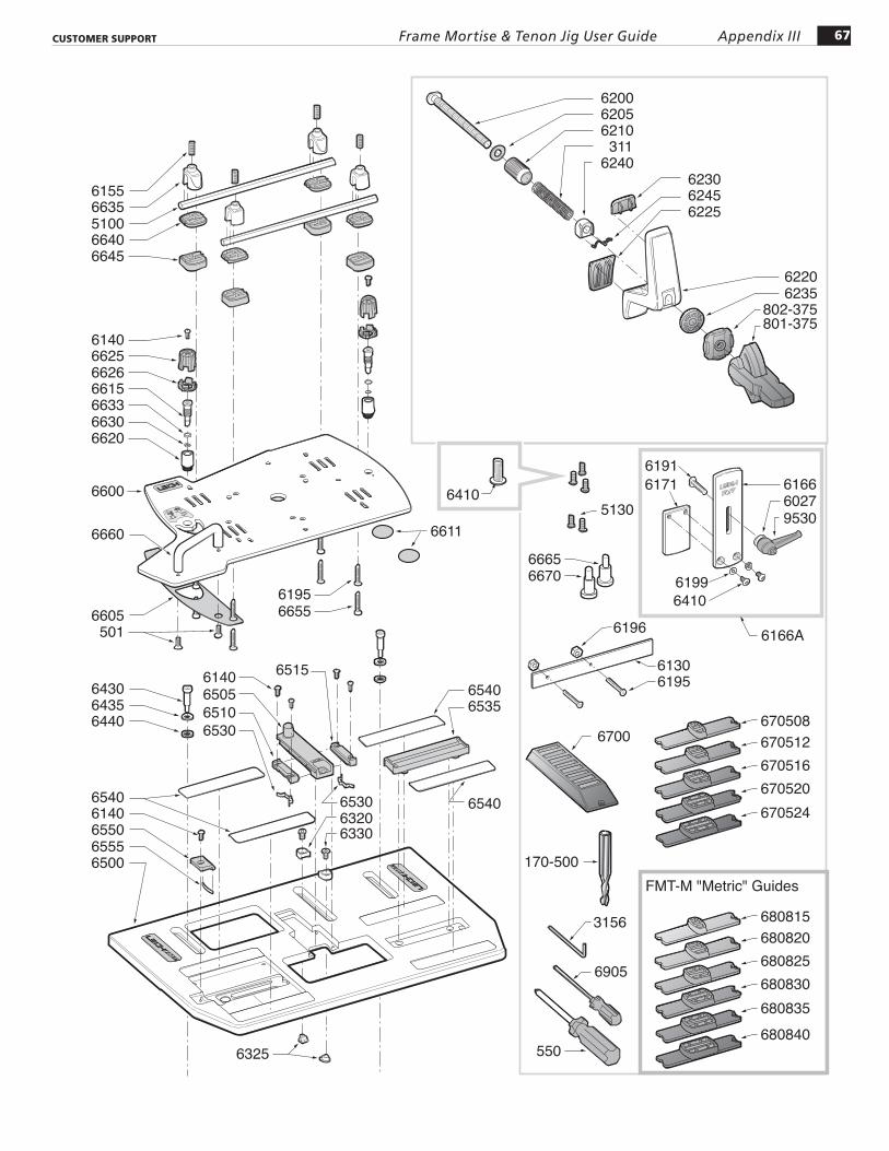
6300 1 Intermediate Plate Assembly c/w pressed-in Pins 6310 4 pairs Wedge Blocks 6315 4 Wedge Block Compression Springs 6320 4 Limit Stops 6325 4 Limit Stop Nuts 6330 4 10-24 x 3/8" Hex Socket Nyloc Flat Hd Machine Screws 6335 2 UHMW Glides
6400 1 Table Clamp Rod 6405 1 Table Clamp Handle 6406 1 Clamp Handle Sleeve - Lower 6407 1 Clamp Handle Sleeve - Upper 6410 6 10-24 x 3/8" Hex Socket Button Hd Cap Screw 6415 2 "Pull Down" Clamp Block 6420 1 LH "Push-Up" Clamp Sleeve 6425 1 RH "Push-Up" Clamp Sleeve 6430 2 Hex Socket Hd Shoulder Screws 1/4" x 3/4" (10-24) 6435 2 1/4" Flat Washers SS 6440 2 1/4" Fiber Washers 6445 1 5/32" x 1" Spring Pin 6455 1 Snap Ring 3/8" x .035" thick
6500 1 Table Plate Assembly c/w Decals & Teflon Pads 6505 1 Sight 6510 1 LH Sight Rail 6515 1 RH Sight Rail 6530 2 Sight Rail Spring Detents 6535 1 RH Guide Pin "Track" 6540 4 Teflon Decal Pads 6550 1 Guide Latch 6555 1 Guide Latch Spring
6600 1 Sub-Base Plate Assembly c/w Decals & Teflon Pads 6605 1 LH Teflon Pad 6611 2 Teflon Discs 6615 2 Guide Pins 6620 2 Guide Pin Bushes 6625 2 Guide Pin Knobs 6626 2 Guide Pin Height Washers 6630 2 O-rings 4.5mm I.D. x 1mm 6633 2 O-rings 7.0mm I.D. x 1mm 6635 4 Sub-Base U-posts ( includes screws 6155 and 6195) 6640 4 "Low" Shim-Spacers 6645 4 "High" Shim-Spacers 6655 4 8-32 x 1" No.2 Sq Dr Flat Hd Machine Screws (for High-Shims) 6660 1 Sub-Base Handle 6665 1 "INCH" Mandrel (1/4" and 1/2") 6670 1 "METRIC" Mandrel (8mm and 12mm)
67Appendix IIIFrame Mortise & Tenon Jig User GuideCUSTOMER SUPPORT
61406550
6540
6535
6540
6540
6665
6196
6195
6700
FMT-M "Metric" Guides
3156
550
6905
170-500
670508670512670516670520670524
680815680820680825680830680835680840
6130
6440
64306435
653063206330
6530
65056140
6510
6515
65556500
66156633
662666256140
66406645
51006635
802-375801-375
62356220
62456225
6230
311 6240
62106205 6200
6155
66306620
6660
6600
619566556605
501
6325
6670
6410 61666171
61996410
6191
6166A
602795305130
6611
68 Appendix III Frame Mortise & Tenon Jig User Guide CUSTOMER SUPPORT
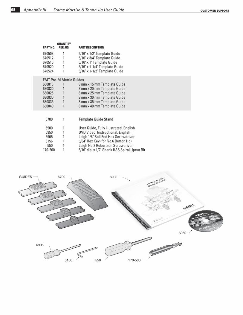
QUANTITY PART NO. PER JIG PART DESCRIPTION
670508 1 5/16" x 1/2" Template Guide 670512 1 5/16" x 3/4" Template Guide 670516 1 5/16" x 1" Template Guide 670520 1 5/16" x 1-1/4" Template Guide 670524 1 5/16" x 1-1/2" Template Guide
FMT Pro-M Metric Guides 680815 1 8 mm x 15 mm Template Guide 680820 1 8 mm x 20 mm Template Guide 680825 1 8 mm x 25 mm Template Guide 680830 1 8 mm x 30 mm Template Guide 680835 1 8 mm x 35 mm Template Guide 680840 1 8 mm x 40 mm Template Guide
6700 1 Template Guide Stand
6900 1 User Guide, Fully illustrated, English 6950 1 DVD Video, Instructional, English 6905 1 Leigh 1/8" Ball End Hex Screwdriver 3156 1 5/64" Hex Key (for No.6 Button Hd) 550 1 Leigh No.2 Robertson Screwdriver170-500 1 5/16" dia. x 1/2" Shank HSS Spiral Upcut Bit
GUIDES 6700 6900
3156 550 170-500
6950
6905
CUSTOMER SUPPORT
FMT PRO Appendix IV
69
AUSTRALIA & NEW ZEALANDMaxis Distribution128 Ingleston Rd., Wakerley, Qld., 4154AustraliaTel: 1300 767 366Tel (Int.) +61 7 3292 0392Email: [email protected]: www.maxis.com.au
CHINAHarvey Industries Co., Ltd.68-10 Suyuan AvenueJiangning District Nanjing 211100, ChinaTel: (0)86 5792 8869 / 5792 8021Fax: (0)86 5792 8826Email: [email protected]: www.harveyworks.cn
FRANCEEts Bordet23 Rue Traversiere 93556Montreuil Cedex, FranceTel: 01 48 58 28 39Fax: 01 48 58 48 58Email: [email protected]: www.bordet.fr
GERMANY, AUSTRIA & SWITZERLANDHacker GmbHHolzbearbeitungsmaschinenTraberhofstraße 103 D-83026 RosenheimDeutschlandTel: 08031 269650Fax: 08031 68221Email: [email protected]: www.leigh.de
ITALYFerrari Macchine Legno SRLVia Gallarata 74/76/7820019 Settimo M.se (MI) ItalyTel: 39 02 335 010 95Fax: 39 02 335 005 27Email: [email protected]: www.ferrarimacchine.com
JAPANOff Corporation Inc.323-1 Yanbara, Shimizu-ku, Shizuoka-shiShizuoka-ken, Japan 424-0002Tel: 81-50-3816-0115Fax: 81-54-367-6515Email: [email protected]: www.off.co.jp
KOREALeigh Korea1st Floor, Yongyu Building, 25-3 Neung Pyung-Ri, Opo-Eup, Kwangju-Si Kyunggi-do, KoreaTel: 82 (0) 70-8252-0988Fax: 82 (0) 31-765-5602Email: [email protected]: www.leigh.co.kr
NETHERLANDS, BELGIUM & LUXEMBOURGHoutbewerking Krielaart9217RR Nijega, NetherlandsTel: +31 512 354 770Email: [email protected]: http://www.leighjigs.nl
RUSSIAUnicom Ltd.Nikitskij Boulevard 12Moscow, 119019, RussiaTel: 7 (495) 690 0454Email: [email protected]: www.leighjigs.ru
SOUTH AFRICAHardware CentrePO Box 4059, Randburg 2125South AfricaTel: +27 011 791-0844/46Fax: +27 011 791-0850Email: [email protected]: www.hardwarecentre.co.za
SWEDENToolbox Sweden ABBruksgatan 3, S-597 30Atvidaberg, SwedenTel: 46 120 854 50Fax: 46 120 854 69Email: [email protected]: http://www.toolbox.se
UNITED KINGDOM & IRELANDAxminster Tools & MachineryHeadquarters, Unit 10, Weycroft AvenueAxminster, DevonEX13 5PH United KingdomTel: 0800 371822Text: 07786 200699Email: [email protected]: www.axminster.co.uk/leigh
© 2002 Leigh Industries Ltd. All rights reserved. No part of this publication may be reproduced, stored in a retrieval system, or transmitted in any form or by any means, electronic, mechanical, recording, or otherwise, without the prior written permission of Leigh Industries Ltd. Updated 04/2017
Distributors
MAILING ADDRESS
Leigh Industries Ltd.
P.O. Box 357
Port Coquitlam, B.C.
Canada V3C 4K6
LOCATION
Leigh Industries Ltd.
1615 Industrial Ave.
Port Coquitlam, B.C.
Canada V3C 6M9
EMAIL/WEB
Customer Service [email protected]
Technical Support [email protected]
Websitewww.leighjigs.com
Manufacturer: Canada/USA
Our Commitment to You Leigh Industries takes pride in its commitment to providing excellence in customer service and support. This user guide is designed to provide you with the answers to any questions you have. However, if you require assistance, please feel free to contact our technical support staff or a distributor listed below.
NOTE: Email can be useful, but technical queries usually raise queries from us. A phone call is the quickest and most convenient way to get queries answered, either directly to Leigh (toll free in N. America) or to your national distributor. –Thanks!
TEL/FAX
Customer Service and Technical Support800-663-8932 (Canada/USA)604-464-2700 (Tel.)604 464-7404 (Fax.)
Customer Support

Printed in Canada
Joining Tradition with Today
Leigh Router Joinery Jigs


![Competing Transformations[Prnt Fmt]](https://img.pdfslide.us/doc/110x75/5400655bdab5caaf758b46eb/competing-transformationsprnt-fmt.jpg)