Embed Size (px)
Citation preview
BELAR ELECTRONICS LABORATORY, INC.
119 LANCASTER AVENUE P.O. BOX 76 DEVON, PA 19333-0076 USA VOICE (610) 687-5550 FAX (610) 687-2686 www.belar.com [email protected] [email protected] [email protected]
BELAR FMHD-1
PRECISION DIGITAL FM HD MONITOR/ANALYZER
Guide to Operations 2011/06/22
©2011

WARRANTY, FACTORY RECALIBRATION AND FACTORY SERVICE
FOR ANY ASSISTANCE, CONTACT YOUR BELAR SALES REPRESENTATIVE OR CUSTOMER SERVICE
AT THE BELAR FACTORY.
Immediately upon receiving your equipment, please make a careful inspection for any shipping damage. If damage is found or
suspected, please notify the carrier at once and then contact your dealer or the BELAR factory. We strongly encourage you to
save the shipping carton and shipping materials supplied with your equipment. They are specially designed to properly protect
your equipment, and in the event that you need to return it for service, only these OEM shipping materials can ensure its safe
return to our factory.
All BELAR products are warranted against defects in materials and workmanship. This warranty applies for one year from the
date of delivery, FOB factory or, in the case of certain major components listed in the instruction manual, for the specified
period. BELAR will repair or replace products which prove to be defective during the warranty period provided that they are
returned to BELAR pre-paid. No other warranty is expressed or implied. BELAR is not liable for consequential damages.
A RETURN MATERIAL AUTHORIZATION NUMBER MUST BE OBTAINED FROM BELAR IN ADVANCE
OF RETURN.
$ Please call (610-687-5550) or email ([email protected]) to request an RMA number to display on the
outside of your shipping carton and all paperwork.
$ A written statement with the name, address, telephone number & email address together with a brief
description of the work requested, must accompany all returns.
$ The customer shall be responsible for all costs of transportation and insurance to and from the BELAR
factory, and all such costs must be prepaid.
PLEASE VISIT: WWW.BELAR.COM AND REGISTER YOUR PRODUCT SO WE MAY KEEP YOU
INFORMED OF THE LATEST HARDWARE AND SOFTWARE UPDATES.
We no longer ship PC Control Software with the units. Please visit www.belar.com and download the latest WizWin and Server PC Control Software. Software updates will be posted on our website periodically. The FMHD-1 can be updated in the field using the PC Software.

1. Description............................................................................................................................... 1
2. Front Panel ............................................................................................................................... 3
3. Rear Panel ................................................................................................................................ 5
4. Main Tuning Screen ................................................................................................................ 6
5. SIS Data Screen ....................................................................................................................... 7
SIS Header Information ................................................................................................................................................................ 7
SIS Data ........................................................................................................................................................................................ 7
6. PAD Data Screen ..................................................................................................................... 8
PSD Data Available ...................................................................................................................................................................... 8
PAD Header Data ......................................................................................................................................................................... 8
PAD Data ...................................................................................................................................................................................... 8
7. Audio Bargraphs Screen .......................................................................................................... 9
8. Total, Pilot, Left, Right, L+R, and L−R Screen .................................................................... 10
9. RF Spectrum Screen .............................................................................................................. 11
10. Time Alignment Screen ..................................................................................................... 12
11. Program Selection Screen .................................................................................................. 13
12. BER Data Screen ............................................................................................................... 14
13. Alarms/Relays Screen ........................................................................................................ 15
14. Popup Menus ..................................................................................................................... 16
15. Software Setup and Unit Update Information ................................................................... 23


BELAR ELECTRONICS LABORATORY, INC. Page 1
1. DESCRIPTION
The BELAR FMHD-1 is a state of the art HD Radio monitor designed to support the needs of today’s broadcaster well into the future. The monitor decodes the HD Radio signal and analog FM signal simultaneously displaying HD Radio status, data, time alignment, and configuration information, as well as total, pilot, L, R, L+R and L−R metering and RF spectrums. The two rack high unit with 640x240 color LCD display and rotary encoder provide a detailed clean and simple user interface.
Based on the latest decoder from Ibiquity, the FMHD-1 currently supports monitoring multiple audio streams and simultaneous monitoring of two streams with and optional second plug in HD decoder. The units 8 user assignable analog audio outputs and 3 assignable AES−3ID outputs provide support for a wide variety of broadcast scenarios including multi-casting and surround sound.
In addition to an antenna input for monitoring off the air, the FMHD-1 has two high level RF inputs for transmitter site operation. The dual RF inputs allow for monitoring at installations using two transmitters to generate the combined Analog/HD signal.
Older wideband Analog FM monitors out in the field may require pre-filtering in order to remove HD Radio sidebands. The FMHD-1 provides two variable bandwidth, high quality filtered analog composite outputs for driving these monitors eliminating interference.
The FMHD-1 has both RJ-45 10/100 Base T Ethernet and RS-232 computer interfaces. When used in conjunction with the Wizard for Windows software the FMHD-1 can be viewed remotely with various PC graphing and logging functions available. The unit also provides 4 user assignable relay closures used to indicate alarm conditions.

Page 2 FMHD-1
Notes:

BELAR ELECTRONICS LABORATORY, INC. Page 3
2. FRONT PANEL
The front panel of the FMHD-1 consists of a 640 x 240 pixel color LCD display and a rotary encoder with push switch.
To change screens rotate the encoder
To select a screen and change any available parameters push on the knob.
Once a screen is selected use the cursor to select the parameters on a given screen.
To change a parameter select and click on it.
Selected parameters change from yellow to green.
When finished click again to return to the cursor for that screen.
To exit the screen select the icon and click it.
The encoder now returns to changing screens.
To access the popup menus press and hold down the encoder for 2 seconds.
To navigate the popup menus rotate the encoder to highlight a menu choice and click the encoder.
To exit the pop menu at any time, hold down the encoder for 2 seconds.
The front panel headphone jack is assignable to any available audio source. To assign the left and right channels see the Outputs popup menu under Settings.

Page 4 FMHD-1

BELAR ELECTRONICS LABORATORY, INC. Page 5
3. REAR PANEL
High Level RF Inputs .................................................................................... 87.5 to 108.0 MHz, 1 to 10 Vrms, 50Ω, BNC connector
Antenna Input ........................................................................................... 87.5 to 108.0 MHz, 100µV sensitivity, 75Ω, F connector
Analog Composite Outputs ................................................................... 1.5 Vrms @ 100% = 75 kHz deviation, 75Ω, BNC connector
Digital Composite Outputs ........................................................................ LVDS encoded SCLK, FS, and SDATA, RJ-45 connector
AES-3ID Outputs ............................................................................................. AES encoded audio, 1.0Vpk-pk, 75Ω, BNC connector
Analog Audio Outputs ..................................................................................................... +10 dBm, 600 Ω balanced, XLR connector
RS-232 Connector ...................................................................................................................................... Male, 9 pin D connector
PIN # Type Description PIN # Type Description
1 Input CTX 4 Output RTS
2 Input RX 5 Ground GND
3 Output TX 6 - 9 N/C
Ethernet Connector ............................................................................................................................................................... RJ-45
Remote Alarm Connector ................. Female, 15 pin D connector, Form C Relay contacts rated at 10W max, 0.5A max, 200 VDC max.
PIN # Relay # Description PIN # Relay # Description
1 1 CM 8 3 NC
2 1 NC 9 3 NO
3 1 NO 10 4 CM
4 2 CM 11 4 NC
5 2 NC 12 4 NO
6 2 NO 13-15 N/A N/A
7 3 CM

Page 6 FMHD-1
4. MAIN TUNING SCREEN
SCREEN DISPLAY DATA
HD Station Indicator: Indicates HD successful acquisition of carriers.
Digital Audio Indicator: Indicates Decoded HD audio present.
SIS CRC Indicator: Indicates SIS fame with valid CRC present
RF Level: Indicates signal strength in dBm for Antenna input, or percent of full scale input level for High Level inputs. For High Level inputs the potentiometer on the back panel should be adjusted until the RF Level is in the green region for proper operation. For both High Level and Antenna Inputs the RF Level indicates yellow for low signal level values, green for normal levels, and red for overload levels.
HD 1 thru HD 8 Indicators: Indicates presence of an HD audio stream. Green indicates present and selected. Yellow available, but not selected. Red indicates selected, but unavailable.
Service Mode: Indicates FM primary service mode.
MPA CODEC Mode: Indicates codec configuration for currently selected audio program.
CD/NO: Displays the carrier to noise ratio, where CD refers to the total power in both digital sidebands, and NO the noise spectral density. This measurement is calculated in a 1 Hz bandwidth.
QI: The quality of the currently selected audio program in a range from 0-15.
DAAI: Filtered version of the QI. Estimate of the signal quality.
Audio Acquisition Time: The elapsed time in milliseconds between acquisition and digital audio output.
Data Acquisition Time: The elapsed time in milliseconds from acquisition until a SIS frame with a valid CRC is received.
SCREEN SELECTABLE DATA
To select a parameter click on the screen, then use the cursor to select the parameter using the knob, and click again. Adjust the parameter using the knob and click to set the new value.
To exit this screen, select the screen icon (in the upper right corner of the screen) and push the rotary encoder dial to exit the screen command mode and return to the screen selection mode.
Tuning Frequency: Selects the Tuning frequency of the FMHD-1 in 100 kHz steps. The unit tunes to the new frequency as the frequency is changed.
Decoder #1 Program Selection: To switch the audio program of decoder #1, use the cursor to select the program and then click on it. This feature allows available programs to be quickly auditioned by routing the decoder #1(D1) audio outputs to the headphone jack, or audio outputs on the rear panel. See Outputs under the Settings popup menu for audio output assignments. The D1 L, R, L+R, and L−R choices will track the currently selected program of decoder #1.
BELAR ELECTRONICS LABORATORY, INC. Page 7
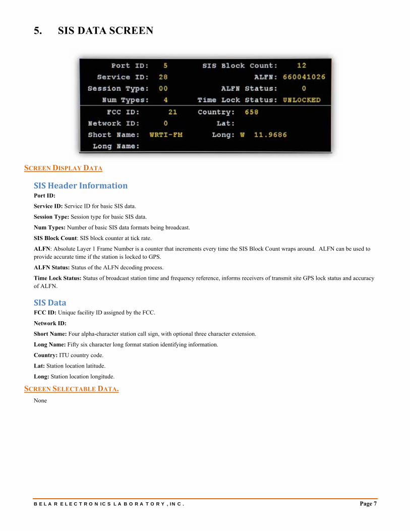
5. SIS DATA SCREEN
SCREEN DISPLAY DATA
SIS Header Information Port ID:
Service ID: Service ID for basic SIS data.
Session Type: Session type for basic SIS data.
Num Types: Number of basic SIS data formats being broadcast.
SIS Block Count: SIS block counter at tick rate.
ALFN: Absolute Layer 1 Frame Number is a counter that increments every time the SIS Block Count wraps around. ALFN can be used to provide accurate time if the station is locked to GPS.
ALFN Status: Status of the ALFN decoding process.
Time Lock Status: Status of broadcast station time and frequency reference, informs receivers of transmit site GPS lock status and accuracy of ALFN.
SIS Data FCC ID: Unique facility ID assigned by the FCC.
Network ID:
Short Name: Four alpha-character station call sign, with optional three character extension.
Long Name: Fifty six character long format station identifying information.
Country: ITU country code.
Lat: Station location latitude.
Long: Station location longitude.
SCREEN SELECTABLE DATA.
None

Page 8 FMHD-1
6. PAD DATA SCREEN
SCREEN DISPLAY DATA
PSD Data Available The colored HD1 thru HD8 text indicates which PSD data stream is currently displayed and what streams are available. The Green highlighted HD# is the currently displayed and available PSD data; the remaining Yellow highlighted HD#’s are available. If a HD# is selected which is unavailable it is highlighted Red. White or un-highlighted HD#’s have no PSD Data preset.
PAD Header Data Service ID: Identifies destination service/application for PSD packets.
Session Type: Identifies session type for service/application received PSD packets.
Num Packets Available: The number of PSD packets remaining in the queue to be read by the host.
Port ID: Data port for PSD data.
Packet Length: Length in bytes of PSD packet.
Sequence Number: Allows service/application to reorder PSD packets in the event they were received out of order by the decoder.
Overflow Status: Set if output queue has overflowed.
PAD Data Title: Program song title.
Artist: Program artist.
Album: Program album.
Genre: Program genre.
Comment: Program comment.
SCREEN SELECTABLE DATA
PSD Data Stream: To monitor a particular PSD data stream use the cursor to select the HD# and click on it. If data is available for that channel the HD# will become highlighted Green and the PSD data will be displayed. Otherwise, the HD# will become highlighted Red indicating the PSD data stream is not present.

BELAR ELECTRONICS LABORATORY, INC. Page 9
7. AUDIO BARGRAPHS SCREEN
SCREEN DISPLAY DATA
The colored ANL and HD1 thru HD8 text indicates which audio program is currently displayed and what audio streams are available. The Green highlighted ANL or HD# is the currently displayed and available audio program, the remaining Yellow highlighted ANL or HD#’s are available. If the ANL or a HD# is selected which is unavailable it is highlighted Red. White or un-highlighted ANL or HD#’s have no audio program present.
Each HD audio program available requires a separate decoder installed in the FMHD-1. With one decoder installed the audio program choices are ANL and the HD audio selected in the Program Selection Screen. An optional second decoder allows a second HD program. In the future the unit will accommodate up to four decoders and four HD streams simultaneously.
The bar graph screen shows the Peak (Red), Average (Yellow), and Min (Green) audio levels in percent. The readings are normalized using the bar graph scaling factor, which has units of dBFS. The scale factor is adjustable from 0.0 to −20.0dBFS, with 0.0dBFS corresponding to digital clipping. The ANL (Analog Main) audio levels are DE-EMPHASIZED and not referenced to 100% at 75 kHz. For flat normalized Analog main modulation readings refer to the Analog Stereo bar graph screen.
SCREEN SELECTABLE DATA
Audio Program: To monitor a particular audio program use the cursor to select the ANL or HD# and click on it. If data is available for that channel the HD# will become highlighted Green and the audio data will be displayed. Otherwise, the ANL or HD# will become highlighted Red indicating the audio program is not present.
Scale factor: Unlike the traditional analog FM peak measurements which are referenced to 100% at 75 kHz deviation, the audio levels in the FMHD-1 are normalized using a scale factor. The scale factor represents the amount of digital headroom in the audio channel and is typically set between −3.0 and −10.0dBFS. Setting the scale factor to normalize the bar graphs to 100% with nominal input levels at the HD encoder will allow the broadcaster to accurately monitor their audio levels.

Page 10 FMHD-1
8. TOTAL, PILOT, LEFT, RIGHT, L+R, AND L−R SCREEN
SCREEN DISPLAY DATA
Total, Pilot, Left, Right, L+R, and L−R: Peak Modulation bar graphs display the Peak (Red), Average (Yellow), and Min (Green) modulation data.
All readings are referenced to 100% at 75 kHz deviation.
SCREEN SELECTABLE DATA
None
BELAR ELECTRONICS LABORATORY, INC. Page 11
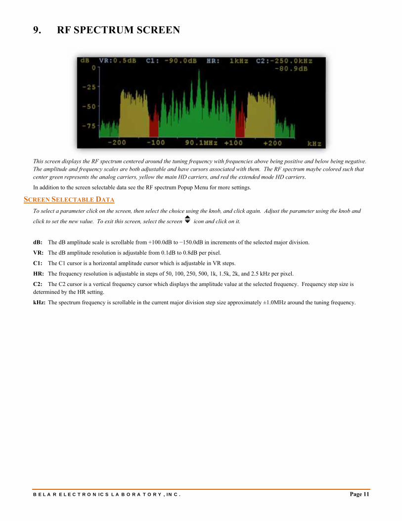
9. RF SPECTRUM SCREEN
This screen displays the RF spectrum centered around the tuning frequency with frequencies above being positive and below being negative. The amplitude and frequency scales are both adjustable and have cursors associated with them. The RF spectrum maybe colored such that center green represents the analog carriers, yellow the main HD carriers, and red the extended mode HD carriers.
In addition to the screen selectable data see the RF spectrum Popup Menu for more settings.
SCREEN SELECTABLE DATA
To select a parameter click on the screen, then select the choice using the knob, and click again. Adjust the parameter using the knob and
click to set the new value. To exit this screen, select the screen icon and click on it.
dB: The dB amplitude scale is scrollable from +100.0dB to −150.0dB in increments of the selected major division.
VR: The dB amplitude resolution is adjustable from 0.1dB to 0.8dB per pixel.
C1: The C1 cursor is a horizontal amplitude cursor which is adjustable in VR steps.
HR: The frequency resolution is adjustable in steps of 50, 100, 250, 500, 1k, 1.5k, 2k, and 2.5 kHz per pixel.
C2: The C2 cursor is a vertical frequency cursor which displays the amplitude value at the selected frequency. Frequency step size is determined by the HR setting.
kHz: The spectrum frequency is scrollable in the current major division step size approximately ±1.0MHz around the tuning frequency.

Page 12 FMHD-1
10. TIME ALIGNMENT SCREEN
The Time Alignment screen displays the polarity, amplitude, and time alignment of the Analog Main and HD Main audio. For both amplitude and time displays the red bar indicates the fast response measurement and yellow indicates the slower average measurement.
The amplitude alignment measurement compares the power in the L+R Main and L+R HD to give an estimate of the relative loudness differences heard when blending from digital to analog or vice-versa. The range is ±20.0dB in 0.1dB increments.
The time alignment measurement, calculates the lead or lag of the analog audio relative to the HD audio in samples of 44.1 kHz or
increments of 22.68µs. The alignment is adjusted in the HD encoder/audio processor. The range is 16384 samples or 372ms.
The polarity indicator shows if the Analog and HD audio are in phase or 180 degrees out of phase. It is possible to have a valid time alignment while having the Analog and HD programs inverted relative to each other. This is undesirable because cancellation occurs during the blend.
SCREEN SELECTABLE DATA
HR: The time alignment display scale is adjustable from, 256 samples (5.8ms) to 16384 samples (372ms).

BELAR ELECTRONICS LABORATORY, INC. Page 13
11. PROGRAM SELECTION SCREEN
The Program Selection screen displays all the available HD programs with the selected programs in green and the other programs in yellow. If a program is selected which is not present the box is highlighted Red. The first column represents HD decoder #1 and the second column the optional HD decoder #2, etc. Only one program may be selected from each column allowing one HD program to be decoded for each HD decoder installed. HD1 represents the HD Main program with HD2−HD8 corresponding to Supplemental Programs 1−7. The selected HD audio programs are displayed as available choices on the Audio Bar Graph screen and are available for output to the XLR, Headphone, or AES outputs.
Decoder #1 is used to calculate the time alignment and audio level alignment, if any program other than HD1 is selected of this decoder, the time/level alignment graphs will indicate “out of range”.
SCREEN DISPLAY DATA
Program Type: The numeric program type code for each audio stream is displayed along with the associated program type description text.
SCREEN SELECTABLE DATA
Program Selection: Use the cursor to select the desired decoder D1 thru D4, click on the D# and it will highlight green. Once a decoder has been selected use the cursor to choose the HD program. To exit a particular decoder program select, click again on the highlighted Green D#. Available HD programs are highlighted Green and Yellow, the selected program will turn green, if present, otherwise it will turn red. Any audio outputs assigned to an unselected yellow or unavailable red will be muted.
Page 14 FMHD-1
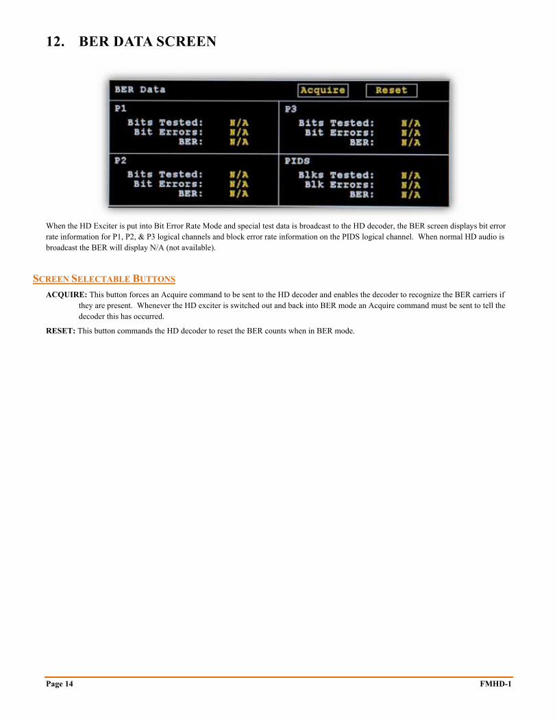
12. BER DATA SCREEN
When the HD Exciter is put into Bit Error Rate Mode and special test data is broadcast to the HD decoder, the BER screen displays bit error rate information for P1, P2, & P3 logical channels and block error rate information on the PIDS logical channel. When normal HD audio is broadcast the BER will display N/A (not available).
SCREEN SELECTABLE BUTTONS
ACQUIRE: This button forces an Acquire command to be sent to the HD decoder and enables the decoder to recognize the BER carriers if they are present. Whenever the HD exciter is switched out and back into BER mode an Acquire command must be sent to tell the decoder this has occurred.
RESET: This button commands the HD decoder to reset the BER counts when in BER mode.

BELAR ELECTRONICS LABORATORY, INC. Page 15
13. ALARMS/RELAYS SCREEN
SCREEN SELECTABLE DATA
To select a parameter click on the screen, then select the event using the knob, and click again. Use the encoder to select the event parameter and click, set the new value, and click again. To exit the event, select it, and click. The events scroll as the cursor is moved thru
the list. To exit this screen, select the screen icon and click on it.
Events can be set to trigger any one of four relay closures, 4 email addresses, or display in a popup alarm window on the FMHD-1.
Loss of RF (ANT): Loss of RF on Antenna Input. Threshold −10.0 to −80dB; Time 1 to 60 sec.
Loss of RF (HL): Loss of RF on High Level Input. Threshold 0 to 100.0%; Time 1 to 60 sec.
Loss of Total: Loss of Peak Total Modulation. Threshold 0 to 150.0%; Time 1 to 60 sec.
Total Peak LED: Total Peak Level Exceeded. Threshold 0 to 150.0%; Time N/A.
Loss of L+R: Loss of L+R or Mono program. Threshold 0 to 150.0%; Time 1 to 60 sec.
Loss of Pilot: Loss of Pilot Tone. Threshold 0 to 150%; Time 1 to 60 sec.
HD Station LED: Indicates HD station present. Threshold N/A; Time N/A.
HD Audio LED: Indicates HD Audio available. Threshold N/A; Time N/A.
SIS CRC LED: Indicates SIS CRC data blocks detected. Threshold N/A; Time N/A.
QI Value: Quality Indicator. Threshold 0 to 15; Time 1 to 60 sec.
CD/NO: Carrier Noise Ratio. Threshold 30.0 to 80.0dB; Time 1 to 60 sec.
Loss of HD1 L+R: Loss of HD1 audio. Threshold 0 to 150.0%; Time 1 to 60 sec.
Loss of HD2 L+R: Loss of HD2 audio. Threshold 0 to 150.0%; Time 1 to 60 sec.
Loss of HD3 L+R: Loss of HD3 audio. Threshold 0 to 150.0%; Time 1 to 60 sec.
Loss of HD4 L+R: Loss of HD4 audio. Threshold 0 to 150.0%; Time 1 to 60 sec.
Loss of HD5 L+R: Loss of HD5 audio. Threshold 0 to 150.0%; Time 1 to 60 sec.
Loss of HD6 L+R: Loss of HD6 audio. Threshold 0 to 150.0%; Time 1 to 60 sec.
Loss of HD7 L+R: Loss of HD7 audio. Threshold 0 to 150.0%; Time 1 to 60 sec.
Loss of HD8 L+R: Loss of HD8 audio. Threshold 0 to 150.0%; Time 1 to 60 sec.
Time Align +: Positive Time Alignment. Threshold 0 to 250 samples; Time 1 to 60 sec.
Time Align −: Negative Time Alignment. Threshold 0 to −250; Time 1 to 60 sec.
Audio Polarity LED -: Audio Polarity In-Phase or 180 degrees. Threshold N/A; Time N/A.
Page 16 FMHD-1
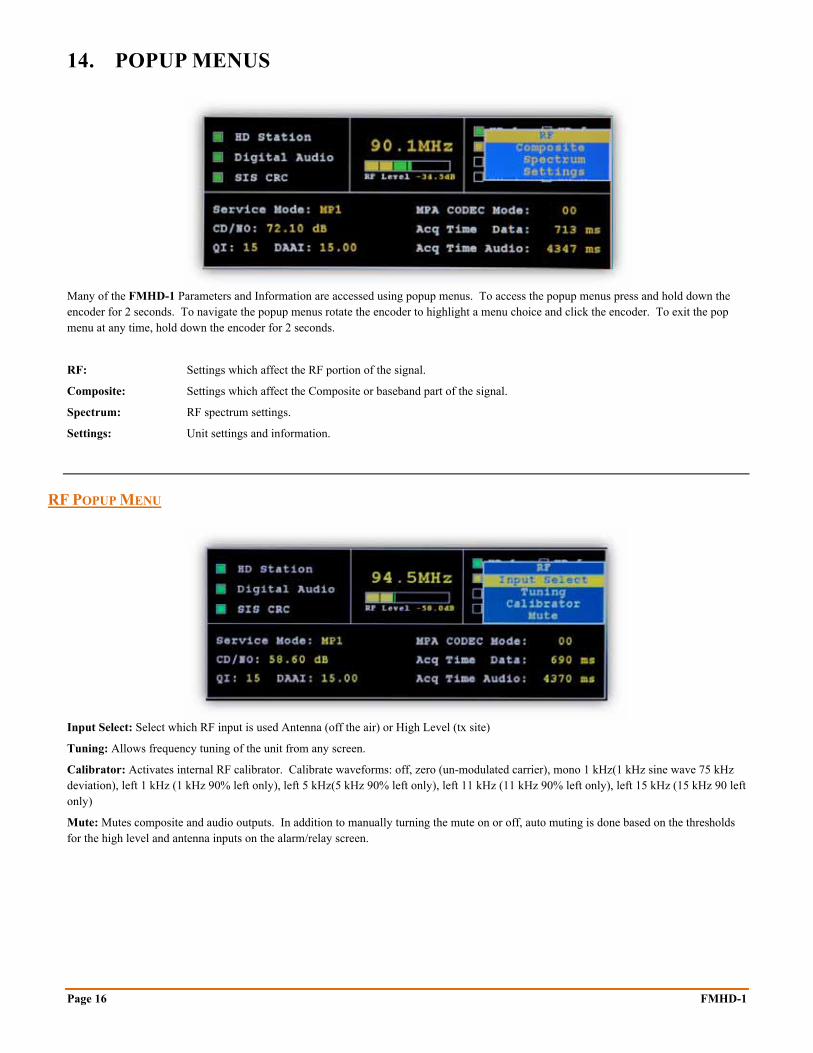
14. POPUP MENUS
Many of the FMHD-1 Parameters and Information are accessed using popup menus. To access the popup menus press and hold down the encoder for 2 seconds. To navigate the popup menus rotate the encoder to highlight a menu choice and click the encoder. To exit the pop menu at any time, hold down the encoder for 2 seconds.
RF: Settings which affect the RF portion of the signal.
Composite: Settings which affect the Composite or baseband part of the signal.
Spectrum: RF spectrum settings.
Settings: Unit settings and information.
RF POPUP MENU
Input Select: Select which RF input is used Antenna (off the air) or High Level (tx site)
Tuning: Allows frequency tuning of the unit from any screen.
Calibrator: Activates internal RF calibrator. Calibrate waveforms: off, zero (un-modulated carrier), mono 1 kHz(1 kHz sine wave 75 kHz deviation), left 1 kHz (1 kHz 90% left only), left 5 kHz(5 kHz 90% left only), left 11 kHz (11 kHz 90% left only), left 15 kHz (15 kHz 90 left only)
Mute: Mutes composite and audio outputs. In addition to manually turning the mute on or off, auto muting is done based on the thresholds for the high level and antenna inputs on the alarm/relay screen.

BELAR ELECTRONICS LABORATORY, INC. Page 17
COMPOSITE POPUP MENU
Filter BW: Selects Composite filter bandwidth: Stereo + RDS (passes stereo plus 57 kHz RDS), Stereo + 67 KHz (passes stereo thru 67 kHz SCA, and Stereo + 92 kHz (passes stereo thru 92 kHz SCA). To reduce the interference from off-air-noise or HD carriers it is recommended that the Composite filter bandwidth be set as low as possible depending on the SCA’s present.
Peak Mod: Adjusts the threshold for the Total peak alarm.
RF SPECTRUM POPUP MENU
Display Mode: The Display Mode affects how the spectrum data is presented, in Real-time mode the spectrum is updated with new data each time, Peak Hold displays the highest value in the last Hold Count value of spectrums, Average displays the average of the last Average Count of spectrums, and Infinite holds the highest values until reset.
Hold Count: Determines how many spectrums are used to compute the maximum values at each data point when the Display Mode = Peak Hold.
Avg Count: Sets how many spectrums are used to compute the spectrum average when the Display Mode = Average.
0 dB Ref Lev: The 0 dB Reference Level normalizes the 0 dB point on the spectrum display to a specific dB value.
Curve Fill: Determines whether the spectrum display is a signal line or filled in from the bottom up.
Colors: Changes the normally Green spectrum display into a multi-color display with Green representing the analog portion, Yellow the normal HD carriers, and red the extended HD carriers.
Mask: Enables the RF spectral mask defined for HD Radio.
LSB Mask: Lower sideband HD carrier mask Level. Adjust the mask based on HD carrier power; −40dB corresponds to a −20.0dB ratio, −32dB to a −14dB ratio, and −20.0dB to −10.0dB ratio.
USB Mask: Upper sideband HD carrier mask level. Allows for individual mask adjustment if for asymmetrical HD carriers.
Measurements: Enables analog and HD power measurements. When measurements are enabled the center frequency is locked to the tuning frequency, and the horizontal resolution is locked at 1 kHz. Averaging is enabled with the count initialized to 50. These settings give the best results.

Page 18 FMHD-1
UNIT POPUP MENU
Time Mode: The Time Mode affects all the peak modulation readings and bar graphs. In Real Time Mode when a peak exceeds the current displayed peak the value is updated immediately to the new value and held for the Hold Time, until either a new peak is detected or the Hold Time is met. In Past Time Mode the unit waits the Hold Time and displays the highest peak which was detected during that time period.
Hold Time: Adjusts the Peak Hold Time from 0.25 to 0.5 − 5.0 seconds in 0.5 second increments.
Infinite: When Infinite Hold is enabled the highest peak values are held until disabled. Infinite Hold affects all the modulation readings and bar graphs.
Remote: Allows or blocks remote connections to the unit via the RS-232 or RJ-45 connector.
Screen Saver: The Screen Saver turns off the LCD displays backlight after a specified period without any encoder activity. The choices are OFF, & 1 to 12 hours. (1 hr increments)
Reset Defaults: To reset the unit back to factory defaults click on the Reset Defaults Button.
Reboot: To reboot the unit click on the Reboot Button.
OUTPUTS POPUP MENU
The FMHD-1 provides 8 channels of analog audio output, 6 channels of AES/EBU output, and a headphone output. Any one of these output jacks maybe assigned any of the available audio:
Mute: Channel is muted.
ANL L, R, L+R, L−R: Analog main channel audio de-emphasized.
HD1 thru 8 L, R, L+R, L−R: HD Audio program muted if not available.
D1 thru D4 L, R, L+R, L−R: HD Audio program selected on the decoder. The audio changes when the decoder program select is changed, it is useful for quickly auditioning all the audio program on one set of outputs. The channel is muted if the selected program or decoder is unavailable.
Analog Ch#1−Ch#8: Routes the specified audio source to the selected Analog Channel.
AES/EBU Ch#1−Ch#6: Routes the specified digital audio source to the selected AES/EBU Channel.
Headphone L and R: Assigns the audio program to the headphone Left and Right Channels.
Headphone Volume: Sets the Headphone volume, range is 1 to 100% in 1% steps.
BELAR ELECTRONICS LABORATORY, INC. Page 19
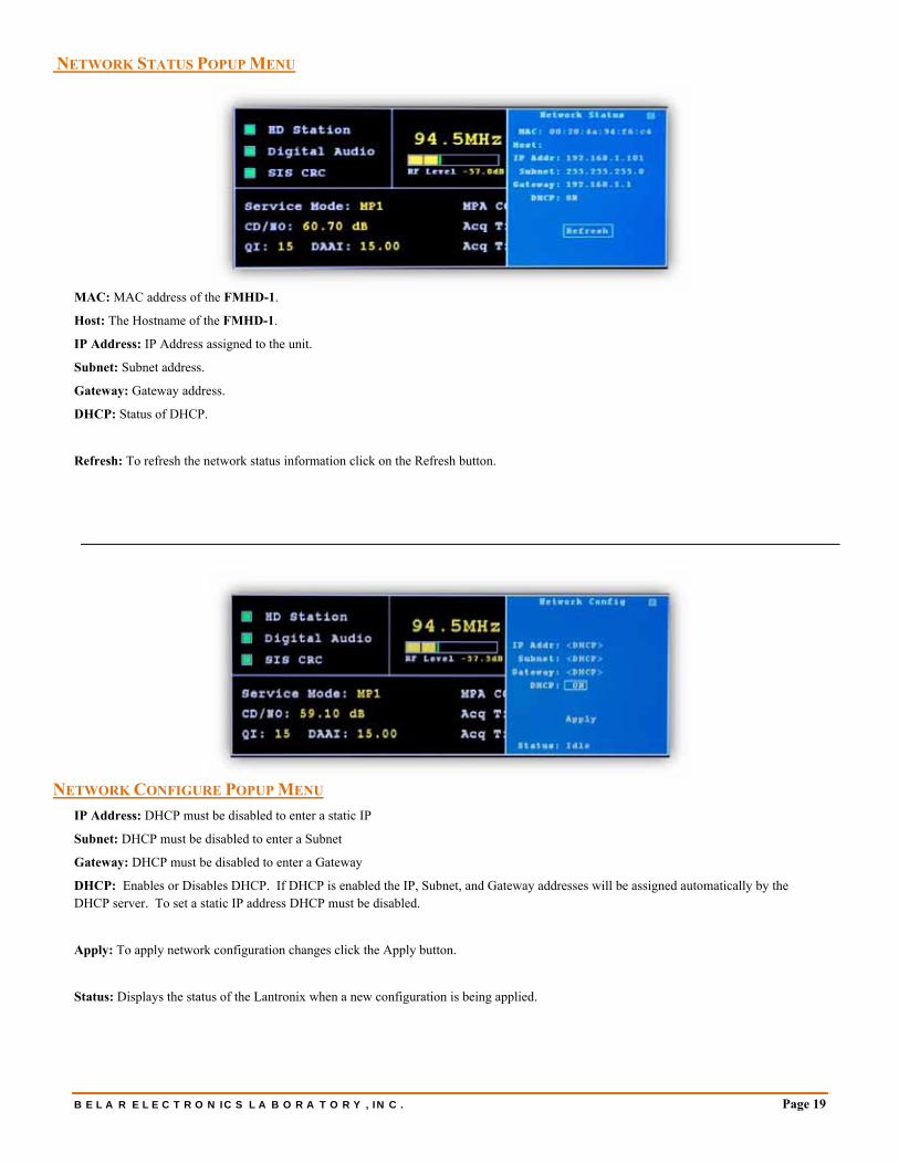
NETWORK STATUS POPUP MENU
MAC: MAC address of the FMHD-1.
Host: The Hostname of the FMHD-1.
IP Address: IP Address assigned to the unit.
Subnet: Subnet address.
Gateway: Gateway address.
DHCP: Status of DHCP.
Refresh: To refresh the network status information click on the Refresh button.
NETWORK CONFIGURE POPUP MENU
IP Address: DHCP must be disabled to enter a static IP
Subnet: DHCP must be disabled to enter a Subnet
Gateway: DHCP must be disabled to enter a Gateway
DHCP: Enables or Disables DHCP. If DHCP is enabled the IP, Subnet, and Gateway addresses will be assigned automatically by the DHCP server. To set a static IP address DHCP must be disabled.
Apply: To apply network configuration changes click the Apply button.
Status: Displays the status of the Lantronix when a new configuration is being applied.

Page 20 FMHD-1
EMAIL SETTINGS POPUP MENU
TO: Email address to which email alerts will be sent. 24 characters max. This field must be set.
CC: Optional email address to which email alerts will be copied. 24 characters max
FROM: Email address alerts will be sent from. 24 characters max. This field must be set.
SUBJECT: Email subject prefix. 12 characters max.
Test: To send a test email click on the Test button.
DECODER POPUP MENU
This screen is used to provide feedback data to better assist the technical staff at BELAR in trouble shooting and resolving and issues involving the decoders that may arise with the unit. There is a screen for each decoder.
Should you experience any problems with your FMHD-1 please note any readings on this screen before rebooting and have them available when contacting BELAR for assistance.
Clear: To clear the decoder error screen click on the Clear Button.
Reset: To reset the decoder click on the Reset Button.
Reboot: To reboot the decoder click on the Reboot Button.

BELAR ELECTRONICS LABORATORY, INC. Page 21
INFO POPUP MENU
BOOT: Processor Boot Code Version and Date
MAIN: Processor Main Code Version and Date
DSP#1-DSP#5: Digital Signal Processors #1 thru #6 Code Versions and Dates
MIC#1-MIC#2: Micro Processor Code Version and Date
UNIT: Unit type configuration
SERIAL #: The unit’s serial number

Page 22 FMHD-1

BELAR ELECTRONICS LABORATORY, INC. Page 23
15. SOFTWARE SETUP AND UNIT UPDATE INFORMATION
The FMHD-1 maybe connected to a computer using the BELAR WizWin Software which can be downloaded from our website at www.belar.com. Connections can be made using the RS-232 port or Ethernet connectors on the rear panel. In addition to accessing the unit remotely the WizWin Software may also be used to update the FMHD-1 firmware in the field.
Please check our website at www.belar.com for the latest software updates as we are always improving our products and adding features.
CONNECTING TO THE UNIT USING THE RJ-45 NETWORK JACK
1. Download and Install the latest version of BELAR WizWin Software from our website. 2. If connecting to a network with a DHCP server in place (the FMHD-1 is shipped with DHCP enabled) connect the FMHD-1 to
your network, on the same subnet as the computer you loaded the WizWin Software, and power cycle the unit. 3. If your network does not have a DHCP server the FMHD-1 will select an APIPA (Automatic Private IP Address) address in the
169.254.xxx.xxx range with a 255.255.0.0 subnet. You can then use an isolated (non DHCP) switch or a crossover cable to connect the FMHD-1 to your computer. You must set the computer IP to the same 169.254.xxx.xxx range with the 255.255.0.0 subnet. (Most computers set to DHCP enabled will default to an APIPA address if no DHCP server is present when they are booted up).
4. To obtain the Units IP address on the FMHD-1 activate the popup menu and select Settings, under Settings select the Network submenu to display the current network information. Make sure that the FMHD-1 is power cycled after the RJ-45 cable has been connected to the unit.
5. Run the WizWin Software and select “Connections” from the window. A pop-up dialog box will appear, select “Connection #1” and click the “Configure” Button. Using the tabs in the Configuration Dialog Box set the “Hardware Type” to “FMHD-1”, set the “Connection Type” to “Network- Ethernet”, and under “Network” set the “IP Address” to the address displayed on the FMHD-1, then set the “PORT” to “10001”, click the “Save” Button to finish. Finally click the “Connect” Button and the unit will connect and display a virtual front panel of the unit.
CONNECTING TO THE UNIT USING THE RS-232 PORT
1. Download and Install the latest version of BELAR WizWin Software from our website. 2. Connect the unit to the computer using a 9 pin serial modem cable. 3. Run the WizWin Software and select “Connections” from the window. A pop-up dialog box will appear, select “Connection #1”
and click the “Configure” Button. Using the tabs in the Configuration Dialog Box set the “Hardware Type” to “FMHD-1”, set the “Connection Type” to “RS-232”, under “RS-232” set the “COM Port” to the COM Port being used on the computer, click the “Save” Button to finish. Finally click the “Connect” Button and the unit will connect and display a virtual front panel of the unit.
UPDATING THE FMHD-1 FIRMWARE
Establish a computer connection to the unit using either the RS-232 Port or the RJ-45 Ethernet Jack. See the previous instructions for connecting to the FMHD-1.
With the WizWin Software running and connected to the FMHD-1 the virtual front panel of the unit should be visible. In the “Connections” Dialog Box click the “Update” Button, a “Update” Dialog Box will appear showing the FMHD-1 units current software version and the Files software version. A warning message will appear if the File software version is the same or older then what is currently in FMHD-1 unit. To start the update click the “Update EPROM” Button, the front panel of the FMHD-1 will show the update status.
UPDATING THE FMHD-1 LANTRONIX ETHERNET CONTROLLER
The Lantronix Ethernet Controller should be updated to version 4.0.0.0 for proper operation of the unit. Establish a computer connection to the unit using either the RS-232 Port or the RJ-45 Ethernet Jack. See the previous instructions for connecting to the FMHD-1.
With the WizWin Software running and connected to the FMHD-1 the virtual front panel of the unit should be visible. In the “Connections” Dialog Box click the “Update” Button, a “Update” Dialog Box will appear showing the FMHD-1 Lantronix current software version and the Files software version. To start the update click the “Update Lantronix” Button, the front panel of the FMHD-1 will show the update status.

BELAR ELECTRONICS LABORATORY, INC.
119 LANCASTER AVENUE P.O. BOX 76
DEVON, PA 19333 USA VOICE (610) 687-5550 FAX (610) 687-2686
www.belar.com [email protected]


![Leferi popup store [lancome] 2014.10.17](https://img.pdfslide.us/doc/110x75/5590d5f51a28ab56148b47a3/leferi-popup-store-lancome-20141017.jpg)