Embed Size (px)
Citation preview
January 2011Page 1 of 31
AUTOMATIC FIRE DETECTION
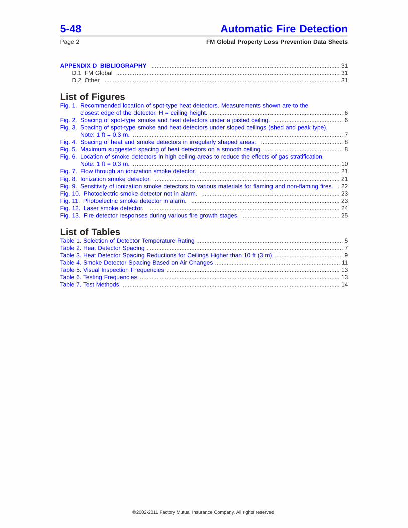
Table of ContentsPage
1.0 SCOPE .................................................................................................................................................... 31.1 Changes ........................................................................................................................................... 3
2.0 LOSS PREVENTION RECOMMENDATIONS ........................................................................................ 32.1 Introduction ....................................................................................................................................... 32.2 Protection ......................................................................................................................................... 3
2.2.1 General ................................................................................................................................... 32.2.2 Heat Detectors ....................................................................................................................... 52.2.3 Smoke Detectors .................................................................................................................... 92.2.4 Flame Detectors ................................................................................................................... 122.2.5 Gas-Sensing Fire Detectors ................................................................................................. 122.2.6 Arc Detectors ....................................................................................................................... 12
2.3 Testing and Maintenance .............................................................................................................. 132.3.1 General ................................................................................................................................. 132.3.2 Testing Methods and Frequency .......................................................................................... 13
3.0 SUPPORT FOR RECOMMENDATIONS ............................................................................................. 153.1 General ........................................................................................................................................... 15
4.0 REFERENCES ..................................................................................................................................... 154.1 FM Global ...................................................................................................................................... 154.2 Other ............................................................................................................................................... 15
APPENDIX A GLOSSARY OF TERMS .................................................................................................... 15APPENDIX B DOCUMENT REVISION HISTORY ..................................................................................... 17APPENDIX C CHARACTERISTICS OF AND APPLICATIONS FOR AUTOMATIC FIRE DETECTORS . 18
C.1 General Information ....................................................................................................................... 18C.2 Heat Detectors .............................................................................................................................. 19
C.2.1 Introduction ......................................................................................................................... 19C.2.2 Fixed-temperature Detectors .............................................................................................. 19C.2.3 Rate-compensation Detectors ............................................................................................ 19C.2.4 Rate-of-rise Detectors ......................................................................................................... 19C.2.5 FM Approved Heat Detectors ............................................................................................. 20
C.3 Smoke Detectors ........................................................................................................................... 20C.3.1 Introduction ......................................................................................................................... 20C.3.2 Ionization Smoke Detectors ................................................................................................ 20C.3.3 Photoelectric Smoke Detectors .......................................................................................... 22C.3.4 Combination Smoke Detectors ........................................................................................... 24C.3.5 Sampling Air Detectors ....................................................................................................... 24C.3.6 Advanced Fire Detection .................................................................................................... 24C.3.7 In-rack Detection ................................................................................................................. 26
C.4 Effects of Temperature Stratification ............................................................................................. 27C.5 Flame Detectors ............................................................................................................................ 27C.6 Gas-Sensing Fire Detectors .......................................................................................................... 28C.7 Arc Detectors ................................................................................................................................ 29C.8 On-site Smoke Generation Tests .................................................................................................. 30
FM GlobalProperty Loss Prevention Data Sheets 5-48
©2002-2011 Factory Mutual Insurance Company. All rights reserved. No part of this document may be reproduced,stored in a retrieval system, or transmitted, in whole or in part, in any form or by any means, electronic, mechanical,photocopying, recording, or otherwise, without written permission of Factory Mutual Insurance Company.
APPENDIX D BIBLIOGRAPHY ................................................................................................................. 31D.1 FM Global ...................................................................................................................................... 31D.2 Other ............................................................................................................................................. 31
List of FiguresFig. 1. Recommended location of spot-type heat detectors. Measurements shown are to the
closest edge of the detector. H = ceiling height. ................................................................................ 6Fig. 2. Spacing of spot-type smoke and heat detectors under a joisted ceiling. .......................................... 6Fig. 3. Spacing of spot-type smoke and heat detectors under sloped ceilings (shed and peak type).
Note: 1 ft = 0.3 m. .............................................................................................................................. 7Fig. 4. Spacing of heat and smoke detectors in irregularly shaped areas. ................................................. 8Fig. 5. Maximum suggested spacing of heat detectors on a smooth ceiling. ............................................... 8Fig. 6. Location of smoke detectors in high ceiling areas to reduce the effects of gas stratification.
Note: 1 ft = 0.3 m. ............................................................................................................................ 10Fig. 7. Flow through an ionization smoke detector. .................................................................................... 21Fig. 8. Ionization smoke detector. ............................................................................................................... 21Fig. 9. Sensitivity of ionization smoke detectors to various materials for flaming and non-flaming fires. . 22Fig. 10. Photoelectric smoke detector not in alarm. ................................................................................... 23Fig. 11. Photoelectric smoke detector in alarm. ......................................................................................... 23Fig. 12. Laser smoke detector. ................................................................................................................... 24Fig. 13. Fire detector responses during various fire growth stages. .......................................................... 25
List of TablesTable 1. Selection of Detector Temperature Rating ........................................................................................ 5Table 2. Heat Detector Spacing ...................................................................................................................... 7Table 3. Heat Detector Spacing Reductions for Ceilings Higher than 10 ft (3 m) ......................................... 9Table 4. Smoke Detector Spacing Based on Air Changes ........................................................................... 11Table 5. Visual Inspection Frequencies ........................................................................................................ 13Table 6. Testing Frequencies ........................................................................................................................ 13Table 7. Test Methods ................................................................................................................................... 14
5-48 Automatic Fire DetectionPage 2 FM Global Property Loss Prevention Data Sheets
©2002-2011 Factory Mutual Insurance Company. All rights reserved.
1.0 SCOPE
This data sheet describes the basic types of automatic fire detectors and provides recommendations forthe installation and testing of these devices. These detectors are the signal-initiating devices discussed inData Sheet 5-40, Automatic Fire Alarm Systems.
1.1 Changes
January 2011. The following changes were made:
• Updated spacing recommendations for heat detectors using response time index (RTI).
• Added guidelines for new detection technologies.
• Provided detection installation recommendations for preaction sprinkler systems.
• Added testing method and frequency tables.
2.0 LOSS PREVENTION RECOMMENDATIONS
2.1 Introduction
An important factor in the reduction of loss from fire is reliable and prompt detection. Automatic fire detectiondevices can provide early warning of fire and smoke, initiate an alarm, and also activate extinguishingsystems. Automatic fire detectors have many applications in commercial, institutional, and industrial facilities,as well as for residential use. Although automatic fire detection devices can be a valuable part of a property’sfire protection system, they are not considered a substitute for automatic sprinklers or other automaticextinguishing systems. Automatic detection and proper notification may, however, provide firefighters withenough advance notice to improve their chances of controlling and extinguishing a fire. Otherwise, extensivefire, water, and smoke damage can result. A detection system may also be valuable where sprinklers arenot installed. There are many different types of detectors on the market. Detectors vary in what they detect,how they detect it, how they are powered, and how they are managed by the fire alarm system.
The Approval Guide, an online resource of FM Approvals, lists FM Approved automatic fire detectors.Information and specific recommendations for unusual or hazardous occupancies are given in FM Globalproperty loss prevention data sheets covering the particular occupancy or equipment involved.
2.2 Protection
2.2.1 General
2.2.1.1 Connect FM Approved automatic fire detectors to initiating device circuits or signaling alarm circuitson fire alarm panels having a secondary power supply in accordance with Data Sheet 5-40, Fire AlarmSystems.
2.2.1.2 If not connected to a control panel, provide detectors with backup or secondary power having aminimum of 24 hours capacity.
2.2.1.3 Base the selection of automatic detection devices on the type and size of fire to be detected andthe response required.
2.2.1.4 To detect incipient fires in high-value or critical areas, such as cleanrooms, telecommunication centers,and critical computer rooms, before flame or noticeable smoke even develops, use very early warning firedetection such as an air-sampling system, or spot-type high-sensitivity smoke detectors. For fastest response,install detectors or sampling points inside electrical/electronic cabinets.
2.2.1.5 Provide spot-type fixed-temperature heat detectors in spaces that may reach high ambienttemperatures under ordinary conditions (such as boiler and electrical wiring rooms), or as required by theapplicable occupancy-specific data sheet.
2.2.1.6 Provide linear heat detection for conveyor belts, cable trays, and rack storage, or as required by theapplicable occupancy-specific data sheet.
2.2.1.7 Use radiant energy sensing detectors to match the radiant emissions expected from the source tobe detected as required by the applicable occupancy-specific data sheet. Since each fuel emits uniquespectra, not all detectors are capable of detecting all fuels.
Automatic Fire Detection 5-48FM Global Property Loss Prevention Data Sheets Page 3
©2002-2011 Factory Mutual Insurance Company. All rights reserved.
2.2.1.8 Use ionization smoke detectors to detect a flaming, well-ventilated, energetic fire, such as thatinvolving a transformer.
2.2.1.9 Use photoelectric smoke detectors to detect a smoldering fire that produces smoke with large,super-micron particulates, such as that involving furniture, paper products, or commodities in cardboardboxes.
2.2.1.10 Use combination ionization/photoelectric smoke detectors for a slow, smoldering fire, such as thatin switchgear and circuit breaker rooms.
2.2.1.11 Use video-imaging fire detection systems for the following commercial and industrial applications:
• Outdoor, open areas such as oil rigs, oil fields, mining operations, and forest products
• Indoor locations such as industrial plants, boiler or other large vessel protection, turbines, and someclean/chemical rooms
2.2.1.12 Protect detectors from mechanical damage; however, do not block detectors, which will make themless responsive. Support or mount them independent of their attachment to the circuit wiring.
2.2.1.13 Ensure signaling from automatic detection devices is received in a constantly attended area.
2.2.1.14 Detection for Preaction and Deluge Sprinkler Systems
Conditions of occupancy or special hazards may require quick application of large quantities of water. Insuch cases, preaction or deluge sprinkler systems may be needed. Fire detection devices to activate preactionand deluge systems may be selected to ensure operation yet guard against premature operation of sprinklers,based on normal room temperature and draft conditions. Apply the following recommendations for detectionsystems employed to activate preaction and deluge sprinkler systems.
2.2.1.14.1 Provide fixed-temperature, rate-of-rise, or combination fixed-temperature/rate of-rise detectiondevices. Do not use smoke or flame detectors unless recommended by the applicable occupancy-specificdata sheet.
2.2.1.14.2 If heat detection is used to activate a preaction system in refrigerated areas, use fixed-temperaturedetectors. Rate-of-rise detectors may false trip when doors are opened or when other abrupt localizedtemperature changes occur.
2.2.1.14.3 For preaction or deluge system activation, use single-zone circuitry for detection and actuationdevices. Cross-zoned circuits unnecessarily delay system activation. Ensure the circuitry is designed to beoperational despite the occurrence of a single fault (ground fault or open circuit).
2.2.1.14.4 Provide separate detection systems, control panels, and release device circuitry for each sprinklersystem. Control panels that can control multiple systems via separate modules in the same panel areacceptable.
2.2.1.14.5 Ensure wiring and control of detection for deluge and preaction systems are totally independentfrom that for other extinguishing systems, such as FM-200 and carbon dioxide, which are often installed alongwith a sprinkler system. The use of common components for any portion of the systems will compromisethe reliability of one system backing up the other.
2.2.1.14.6 Ensure the spacing of heat detectors for activation of preaction systems under smooth ceilingsdoes not exceed that for which it was FM Approved for the specific detector involved. For other than smoothceilings, ensure the spacing of heat detectors does not exceed one-half the FM Approved linear detectorspacing or the full allowable sprinkler spacing, whichever is greater (e.g., if a detector is FM Approved for30 ft by 30 ft and allowable sprinkler spacing is 130 ft2 [12 m2 ] , then maximum allowable linear detectorspacing is 15 ft by 15 ft ). Pilot sprinklers may be installed on the same spacing as the protection sprinklers.
2.2.1.14.7 Determine water demand designs for preaction and refrigerated area sprinkler systems as follows:
A. Base the design on the requirements of a wet system if a preaction system uses electric or pneumaticheat detection methods with detector spacing limited to the greater of 0.5 times the FM Approved lineardetector spacing or the full allowable sprinkler spacing.
B. Base the design on the requirements of a dry system if:
1. a system is designed for a refrigerated area and the detector spacing does not exceed that for whichit was FM Approved, or
5-48 Automatic Fire DetectionPage 4 FM Global Property Loss Prevention Data Sheets
©2002-2011 Factory Mutual Insurance Company. All rights reserved.
2. a preaction system is using pilot sprinklers as the heat detection system, or
3. a preaction system is using electric or pneumatic heat detection methods with detectors spacedbeyond the greater of (a) 0.5 times the linear spacing for which it was FM Approved, or (b) the fullallowable sprinkler spacing.
2.2.2 Heat Detectors
2.2.2.1 General
Use a heat detector with a temperature rating slightly higher than the highest expected ambient temperature.
Table 1 gives the temperature ratings of detectors that can be used for various maximum expected ceilingtemperatures.
Table 1. Selection of Detector Temperature Rating
Temperature Rating Range of Detector Maximum Expected Ceiling Temperature°F °C °F °C
135 to 174 57 to 79 100 38175 to 249 79 to 121 150 66250 to 324 121 to 162 225 107325 to 399 163 to 204 300 149400 to 499 204 to 260 375 191500 to 575 260 to 302 475 246
2.2.2.2 Installation
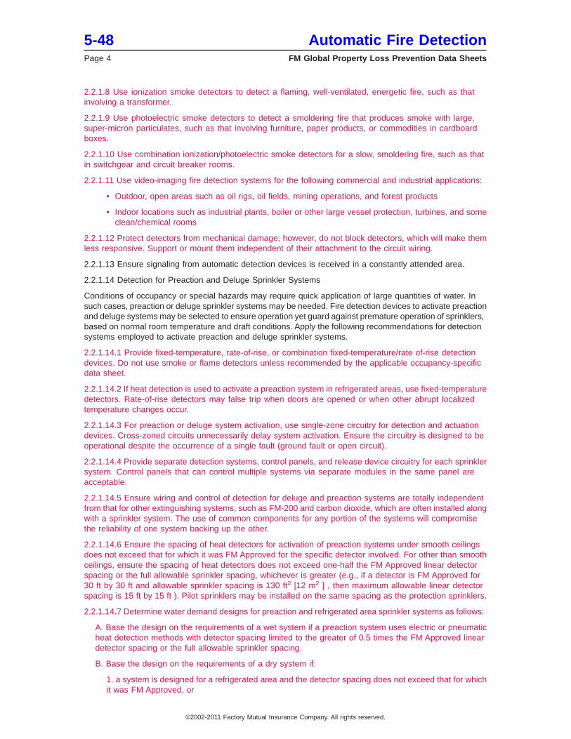
2.2.2.2.1 Locate spot-type heat detectors on or under the ceiling (optimally at about 1%, but not more than6%, of the ceiling height below the ceiling) and not less than 4% of the ceiling height from the side wall.For a low ceiling such as 10-ft (3-m), mounting the detector on the ceiling is acceptable because the detectorsensing element may be at least 1% below the ceiling (1.2 in. for a 10-ft ceiling). A less-desirable alternativelocation is attached to the side wall between 4% and 12% of the ceiling height from the ceiling. (SeeFigure 1.)
2.2.2.2.2 Locate line-type heat detectors under the ceiling. The bulk of the detector wire may be hung optimallyat about 1% (but not more than 6%) of the ceiling height below the ceiling (never firmly attached to ceiling).A less-desirable alternative location is attached to the side wall between 4% and 12% of the ceiling heightfrom the ceiling. (See Figure 1.)
No matter what the detector wire is attached to (pipe, joists, etc.), do not firmly attach it. For example, ifattached to a sprinkler pipe, use hangers to offset the wire from the pipe by at least one pipe diameter. Thewire can be hung above or below a pipe, but if installed on the side of a pipe, hang it on the same side ofevery pipe.
2.2.2.2.3 For beamed construction, if D/H is greater than 0.10 and W/H is greater than 0.30, locate detectorsin each pocket (where D = beam depth, H = ceiling height, and W = width between beams). Otherwise, mountdetectors on the bottoms of the beams.
Automatic Fire Detection 5-48FM Global Property Loss Prevention Data Sheets Page 5
©2002-2011 Factory Mutual Insurance Company. All rights reserved.
2.2.2.3 Spacing
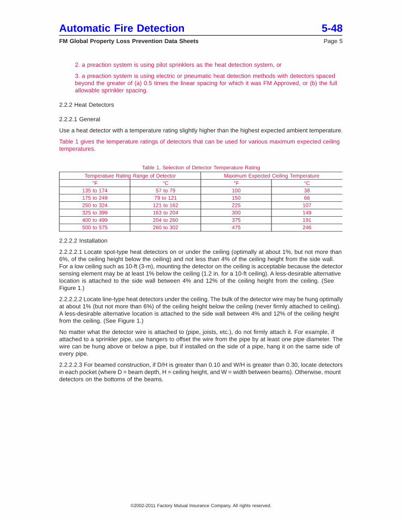
2.2.2.3.1 For open joist construction, locate rows of detectors closest to walls no more than 1/2 of normalspacing from the walls. For example, if a room width is equal to 2.2S, then four rows of detectors are needed;if the room width is 2S, only two rows are needed. (See Figure 2)
2.2.2.3.2 Do not exceed the FM Approved spacing between detectors. The spacing guide for FM Approvedheat detectors on smooth ceilings is dependent on Response Time Index (RTI) of the detector. RTI is a
Fig. 1. Recommended location of spot-type heat detectors. Measurements shown are to the closest edge of the detector.H = ceiling height.
Fig. 2. Spacing of spot-type smoke and heat detectors under a joisted ceiling.
5-48 Automatic Fire DetectionPage 6 FM Global Property Loss Prevention Data Sheets
©2002-2011 Factory Mutual Insurance Company. All rights reserved.
measure of the sensitivity of the heat sensing element as it responds to rising temperature. Table 2 belowprovides the spacing guidelines for all spot-type detectors when placed in best case orientation on a smoothceiling.
Table 2. Heat Detector Spacing
Detector Spacing Label Spacing, ft (m)SPECIAL 10 x 10 (3 x 3)
STANDARD 15 x 15 (4.5 x 4.5)QUICK 20 x 20 (6 x 6)FAST 25 x 25 (8 x 8)
V-FAST 30 x 30 (9 x 9)V2-FAST 35 x 35 (10.5 x 10.5)
2.2.2.3.3 For joisted and beamed ceilings deeper than 3% of the ceiling height, do not exceed 50% of thedetector’s smooth ceiling spacing, as measured at right angles to the joists and beams. Use smooth ceilingspacing in the direction parallel to beams (see Figure 2). If beams project more than 15% of the ceiling height,treat each section between beams as a separate area.
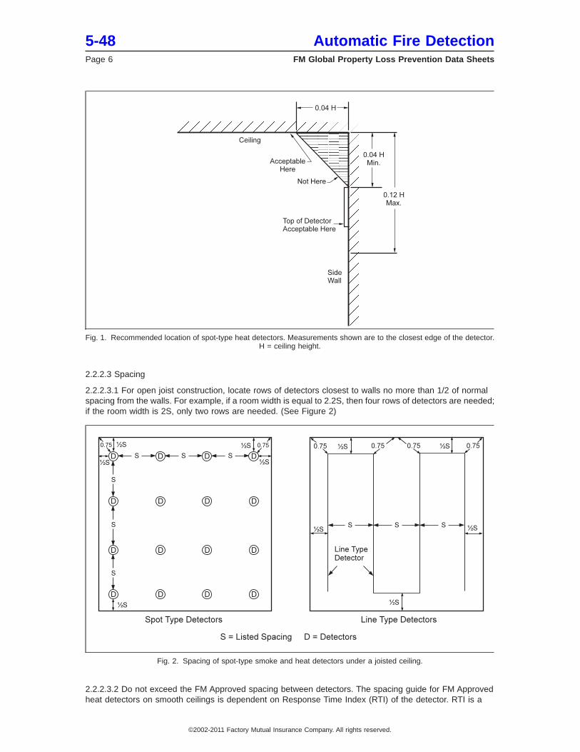
2.2.2.3.4 For peaked ceilings, locate the first row of detectors within 3 ft (0.9 m) of the peak (measuredhorizontally between the two sides of the roof. (See Figure 3.) Space the lower rows based on the horizontalprojection of the ceiling. As slope increases, spaceing up the slope will increase by 1/cos(Θ), where Θ isthe ceiling slope.
2.2.2.3.5 For shed ceilings, locate the first row of detectors within 3 ft (0.9 m) of the top of the ceiling (measuredhorizontally from the wall. (See Figure 3.) Space the lower rows based on the horizontal projection of theceiling.
2.2.2.3.6 For irregularly shaped areas with smooth ceilings, the distance between detectors may be greaterthan the FM Approved spacing; however, ensure the maximum distance from any point on the ceiling to adetector is not greater than 70% of the FM Approved spacing. A detector will cover an area enclosed by anyrectangle that fits in a circle having a radius equal to 0.7 of the FM Approved spacing. See Figure 4.
Fig. 3. Spacing of spot-type smoke and heat detectors under sloped ceilings (shed and peak type). Note: 1 ft = 0.3 m.
Automatic Fire Detection 5-48FM Global Property Loss Prevention Data Sheets Page 7
©2002-2011 Factory Mutual Insurance Company. All rights reserved.
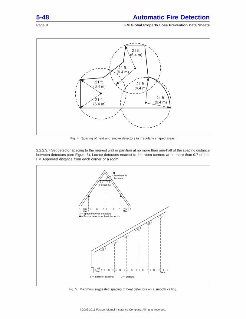
2.2.2.3.7 Set detector spacing to the nearest wall or partition at no more than one-half of the spacing distancebetween detectors (see Figure 5). Locate detectors nearest to the room corners at no more than 0.7 of theFM Approved distance from each corner of a room.
Fig. 4. Spacing of heat and smoke detectors in irregularly shaped areas.
Fig. 5. Maximum suggested spacing of heat detectors on a smooth ceiling.
5-48 Automatic Fire DetectionPage 8 FM Global Property Loss Prevention Data Sheets
©2002-2011 Factory Mutual Insurance Company. All rights reserved.
2.2.2.3.8 For ceilings higher than 10 ft (3 m) and up to 30 ft (9 m), prior to reductions made for beams, joists,or slopes, reduce spacing according to Table 3. This spacing reduction can be used in Hazard Category 1(HC-1) and Hazard Category 2 (HC-2) occupancies (as defined in Data Sheet 3-26) where a small,steady-state fire might occur and where there are no sprinklers. Do not use this spacing reduction inwarehouses where a fast-growing fire can be expected. The purpose of reducing spacing in accordance withTable 3 is to allow a 1000 kW fire to be detected in a certain amount of time regardless of ceiling height.This table does not apply to line-type detectors.
Table 3. Heat Detector Spacing Reductions for Ceilings Higher than 10 ft (3 m)
Ceiling Height (ft) Ceiling Height (m) Multiply Spacing By>10 to 15 >3.0 to 4.5 0.85>16 to 20 >4.5 to 6.0 0.70>21 to 25 >6.0 to 7.5 0.55>26 to 30 >7.5 to 9.0 0.40
2.2.3 Smoke Detectors
2.2.3.1 General
2.2.3.1.1 Install smoke detectors in accordance with the applicable occupancy-specific data sheet.
2.2.3.1.2 Consider spaces below raised floors and above suspended ceilings as separate rooms for thepurpose of detector spacing.
2.2.3.1.3 Do not use smoke detectors where the temperature is expected to exceed 100°F (38°C), the relativehumidity can exceed 93%, or the airflow is greater than 300 ft/min (91 m/min) unless the detector is FMApproved for these conditions. Note that ionization detectors do not work properly in areas with high air flows.In ducts and plenums, use detectors that are FM Approved for this application. Use heat detectors or flamedetectors in areas where the environment makes it impractical to use smoke detectors.
2.2.3.1.4 For areas where cutting and welding is conducted, install motion detectors interlocked with thesmoke detection system to lock out the detection system when occupants are present in the room. Or, use″intelligent″ detectors that change sensitivity settings between day and night or occupied and unoccupiedperiods. Do not use these practices when detectors are interlocked with a protection system.
2.2.3.1.5 Perform a review of fire detection systems whenever there have been any structural orenvironmental changes.
2.2.3.1.6 Use beam detectors in long corridors (where ceiling height is at least 9 ft (2.75 m). Note that forlow ceiling heights, trouble signals or fire alarms can occur if the beam becomes obstructed for too long.
2.2.3.2 Installation
2.2.3.2.1 Locate spot-type ceiling-mounted smoke detectors not less than 4% of the ceiling height from theside wall. See Figure 1.
2.2.3.2.2 For solid joisted and beamed ceilings deeper than 3% of the ceiling height, do not exceed 50%of the detector’s smooth ceiling spacing, as measured at right angles to the joists and beams.
2.2.3.2.3 Use smooth ceiling spacing in the direction parallel to beams. See Figure 2.
2.2.3.2.4 If beams project more than 15% of the ceiling height, treat each section between beams as aseparate area.
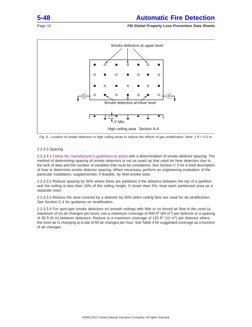
2.2.3.2.5 In areas such as atriums and indoor stadiums, evaluate for stratification under the ceiling.Stratification may cause a heat barrier to form under a high ceiling, which could interfere with smoke reachingthe ceiling. (See Section C.4 for a discussion on temperature stratification.)
Automatic Fire Detection 5-48FM Global Property Loss Prevention Data Sheets Page 9
©2002-2011 Factory Mutual Insurance Company. All rights reserved.
2.2.3.3 Spacing
2.2.3.3.1 Follow the manufacturer’s guidelines to assist with a determination of smoke detector spacing. Themethod of determining spacing of smoke detectors is not as exact as that used for heat detectors due tothe lack of data and the number of variables that must be considered. See Section C.3 for a brief descriptionof how to determine smoke detector spacing. When necessary, perform an engineering evaluation of theparticular installation, supplemented, if feasible, by field smoke tests.
2.2.3.3.2 Reduce spacing by 50% where there are partitions if the distance between the top of a partitionand the ceiling is less than 10% of the ceiling height. If closer than 5%, treat each partitioned area as aseparate room.
2.2.3.3.3 Reduce the area covered by a detector by 50% when ceiling fans are used for de-stratification.See Section C.4 for guidance on stratification.
2.2.3.3.4 For spot-type smoke detectors on smooth ceilings with little or no forced air flow in the room (amaximum of six air changes per hour), use a maximum coverage of 900 ft2 (84 m2) per detector or a spacingof 30 ft (9 m) between detectors. Reduce to a maximum coverage of 125 ft2 (12 m2) per detector wherethe room air is changing at a rate of 60 air changes per hour. See Table 4 for suggested coverage as a functionof air changes.
Fig. 6. Location of smoke detectors in high ceiling areas to reduce the effects of gas stratification. Note: 1 ft = 0.3 m.
5-48 Automatic Fire DetectionPage 10 FM Global Property Loss Prevention Data Sheets
©2002-2011 Factory Mutual Insurance Company. All rights reserved.
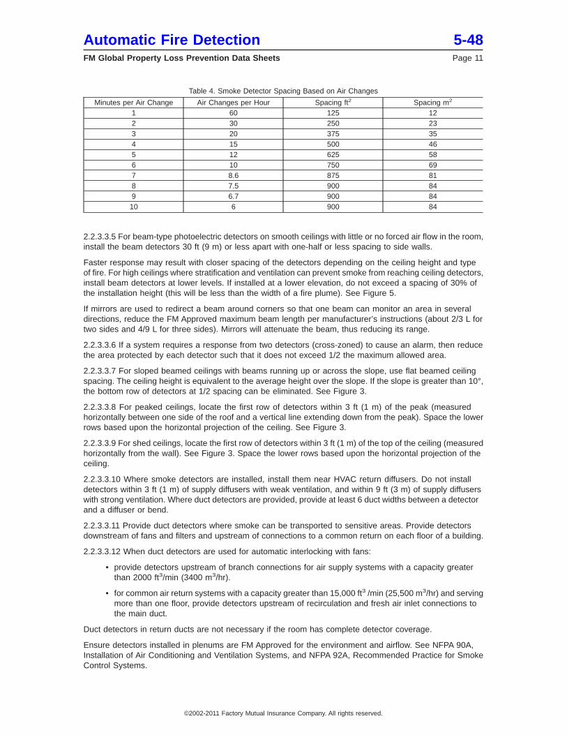
Table 4. Smoke Detector Spacing Based on Air Changes
Minutes per Air Change Air Changes per Hour Spacing ft2 Spacing m2
1 60 125 122 30 250 233 20 375 354 15 500 465 12 625 586 10 750 697 8.6 875 818 7.5 900 849 6.7 900 8410 6 900 84
2.2.3.3.5 For beam-type photoelectric detectors on smooth ceilings with little or no forced air flow in the room,install the beam detectors 30 ft (9 m) or less apart with one-half or less spacing to side walls.
Faster response may result with closer spacing of the detectors depending on the ceiling height and typeof fire. For high ceilings where stratification and ventilation can prevent smoke from reaching ceiling detectors,install beam detectors at lower levels. If installed at a lower elevation, do not exceed a spacing of 30% ofthe installation height (this will be less than the width of a fire plume). See Figure 5.
If mirrors are used to redirect a beam around corners so that one beam can monitor an area in severaldirections, reduce the FM Approved maximum beam length per manufacturer’s instructions (about 2/3 L fortwo sides and 4/9 L for three sides). Mirrors will attenuate the beam, thus reducing its range.
2.2.3.3.6 If a system requires a response from two detectors (cross-zoned) to cause an alarm, then reducethe area protected by each detector such that it does not exceed 1/2 the maximum allowed area.
2.2.3.3.7 For sloped beamed ceilings with beams running up or across the slope, use flat beamed ceilingspacing. The ceiling height is equivalent to the average height over the slope. If the slope is greater than 10°,the bottom row of detectors at 1/2 spacing can be eliminated. See Figure 3.
2.2.3.3.8 For peaked ceilings, locate the first row of detectors within 3 ft (1 m) of the peak (measuredhorizontally between one side of the roof and a vertical line extending down from the peak). Space the lowerrows based upon the horizontal projection of the ceiling. See Figure 3.
2.2.3.3.9 For shed ceilings, locate the first row of detectors within 3 ft (1 m) of the top of the ceiling (measuredhorizontally from the wall). See Figure 3. Space the lower rows based upon the horizontal projection of theceiling.
2.2.3.3.10 Where smoke detectors are installed, install them near HVAC return diffusers. Do not installdetectors within 3 ft (1 m) of supply diffusers with weak ventilation, and within 9 ft (3 m) of supply diffuserswith strong ventilation. Where duct detectors are provided, provide at least 6 duct widths between a detectorand a diffuser or bend.
2.2.3.3.11 Provide duct detectors where smoke can be transported to sensitive areas. Provide detectorsdownstream of fans and filters and upstream of connections to a common return on each floor of a building.
2.2.3.3.12 When duct detectors are used for automatic interlocking with fans:
• provide detectors upstream of branch connections for air supply systems with a capacity greaterthan 2000 ft3/min (3400 m3/hr).
• for common air return systems with a capacity greater than 15,000 ft3 /min (25,500 m3/hr) and servingmore than one floor, provide detectors upstream of recirculation and fresh air inlet connections tothe main duct.
Duct detectors in return ducts are not necessary if the room has complete detector coverage.
Ensure detectors installed in plenums are FM Approved for the environment and airflow. See NFPA 90A,Installation of Air Conditioning and Ventilation Systems, and NFPA 92A, Recommended Practice for SmokeControl Systems.
Automatic Fire Detection 5-48FM Global Property Loss Prevention Data Sheets Page 11
©2002-2011 Factory Mutual Insurance Company. All rights reserved.
2.2.3.3.13 For air sampling systems, design the system so the sampling time from the farthest samplingpoint does not exceed 120 seconds. Depending on design and product, one sampling system may coveran area as large as 20,000 ft2 (1900 m2). Set the detector to signal a trouble condition when sampling airflowis outside of the manufacturer’s specified range.
2.2.3.3.14 For large sampling systems, use multiple sensors, or use a system that can help narrow downthe location of the fire source. Some air sampling systems accomplish this using a valve to alternate thesampling lines after smoke is sensed. Locating the fire source is difficult unless there is a fast-growing fire orthe fire happens to be near a detector or sampling port.
2.2.4 Flame Detectors
2.2.4.1 General Installation and Spacing Guidelines
2.2.4.1.1 Base the specific locations and spacing for flame detectors on an engineering survey of theanticipated conditions in the area to be protected.
2.2.4.1.2 Consider the fuel, location of expected fire, distance, detector characteristics, and potential nuisancesources such as lighting, welding, or reflections from standing water.
2.2.4.1.3 Install the detectors so their field of vision will be adequate to ensure detection of a specified areaof the fire. Test flames are sometimes necessary in order to determine the proper detector locations. Theprotection of an area can be improved by overlapping the areas of cone coverage from the detectors.
2.2.4.1.4 Match the spectral response of the detector to the spectral emissions of the expected fire source.
2.2.4.1.5 Arrange or shield flame detectors so they are not actuated by radiant energy sources that couldproduce nuisance alarms. Infrared lamps, matches, cigarette lighters, and sunlight may induce an unwantedalarm from an infrared detector. Nuisance alarms from ultraviolet detectors may be produced by germicidallamps, X-ray machines, welding arcs, and arcing from electrical motors. FM Approved detectors are testedfor susceptibility to false alarms from common sources.
2.2.4.1.6 Keep the sensors clean or use sensors that can detect a dirty detector window. When usedout-of-doors, use detectors appropriate for this purpose and use shielding if necessary.
2.2.5 Gas-Sensing Fire Detectors
2.2.5.1 General Installation and Spacing Guidelines
2.2.5.1.1 Locate spot-type detectors on the ceiling no less than 4% of the ceiling height from the sidewall,or, if on the sidewall, between 4% and 12% of the ceiling height below the ceiling. On low ceilings, in general,use a 30 ft (9 m) spacing as a guide. Other spacings may be needed depending on ceiling height, conditions,and response requirements.
2.2.5.1.2 Where forced ventilation is present, do not locate detectors within a direct path of the forcedventilation.
2.2.5.1.3 To prevent false operation, select gas-sensing fire detectors based on the design of the detectorand the normal environment of the area to be protected. Do not install them where concentrations ofdetectable gases are present under normal conditions. For instance, unexpected release of some aerosolsprays and hydrocarbon solvents may result in detector operation.
2.2.6 Arc Detectors
2.2.6.1 Provide an arc detection system inside electrical rooms where it is desired to detect damaging arcfaults, which can cause fires and explosions. This type of system will detect an arc in several milliseconds andde-energize the equipment before any damage can be done.
5-48 Automatic Fire DetectionPage 12 FM Global Property Loss Prevention Data Sheets
©2002-2011 Factory Mutual Insurance Company. All rights reserved.
2.3 Testing and Maintenance
2.3.1 General
2.3.1.1 Periodically inspect and test automatic fire detectors to ensure they are in reliable operating condition.Notify appropriate personnel in advance of testing. Document the test procedures and results. Wheredetection is interlocked with a protection system, secure the systems from inadvertent actuation, includingdisconnection of releasing solenoids or electric actuators, closing of valves, or combination thereof, for thesystem for the duration of the test. Return the suppression systems and releasing components to theirfunctional operating condition when system testing is completed.
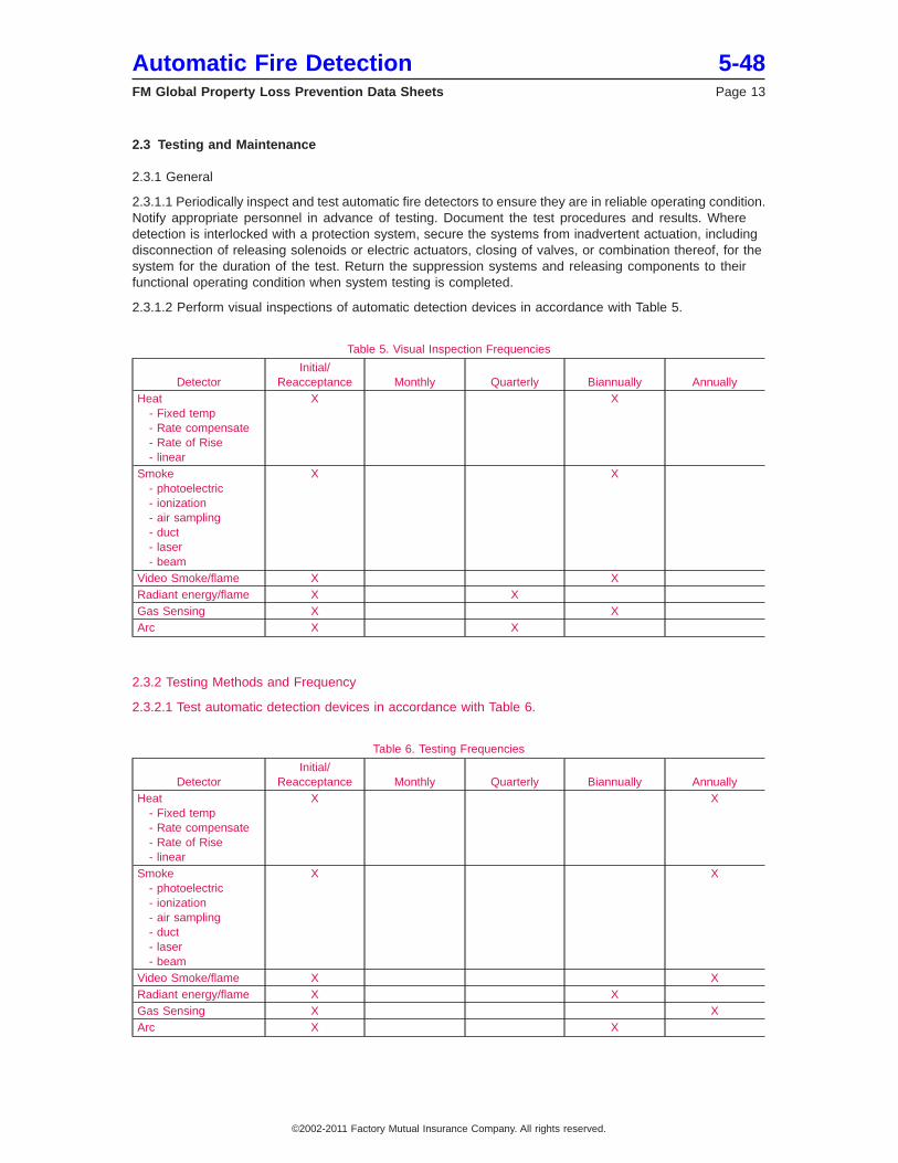
2.3.1.2 Perform visual inspections of automatic detection devices in accordance with Table 5.
Table 5. Visual Inspection Frequencies
DetectorInitial/
Reacceptance Monthly Quarterly Biannually AnnuallyHeat
- Fixed temp- Rate compensate- Rate of Rise- linear
X X
Smoke- photoelectric- ionization- air sampling- duct- laser- beam
X X
Video Smoke/flame X XRadiant energy/flame X XGas Sensing X XArc X X
2.3.2 Testing Methods and Frequency
2.3.2.1 Test automatic detection devices in accordance with Table 6.
Table 6. Testing Frequencies
DetectorInitial/
Reacceptance Monthly Quarterly Biannually AnnuallyHeat
- Fixed temp- Rate compensate- Rate of Rise- linear
X X
Smoke- photoelectric- ionization- air sampling- duct- laser- beam
X X
Video Smoke/flame X XRadiant energy/flame X XGas Sensing X XArc X X
Automatic Fire Detection 5-48FM Global Property Loss Prevention Data Sheets Page 13
©2002-2011 Factory Mutual Insurance Company. All rights reserved.
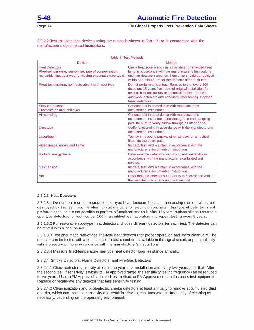
2.3.2.2 Test the detection devices using the methods shown in Table 7, or in accordance with themanufacturer’s documented instructions.
Table 7. Test Methods
Device MethodHeat DetectorsFixed-temperature, rate-of-rise, rate of compensation,restorable line, spot-type (excluding pneumatic tube type)
Use a heat source such as a hair dryer or shielded heatlamp in accordance with the manufacturer’s instructionsuntil the detector responds. Response should be receivedwithin one minute. Reset the detector after each test.
Fixed-temperature, non-restorable line or spot-type Do not perform a heat test. Remove two of every 100detectors 15 years from date of original installation fortesting. If failure occurs on tested detectors, removeadditional detectors and conduct further testing. Replacefailed detectors.
Smoke DetectorsPhotoelectric and ionization
Conduct test in accordance with manufacturer’sdocumented instructions.
Air sampling Conduct test in accordance with manufacturer’sdocumented instructions and through the end samplingport. Be sure to verify airflow through all other ports.
Duct-type Verify functionality in accordance with the manufacturer’sdocumented instructions.
Laser/beam Test by introducing smoke, other aerosol, or an opticalfilter into the beam path.
Video image smoke and flame Inspect, test, and maintain in accordance with themanufacturer’s documented instructions.
Radiant energy/flame Determine the detector’s sensitivity and operability inaccordance with the manufacturer’s calibrated testmethod.
Gas sensing Inspect, test, and maintain in accordance with themanufacturer’s documented instructions.
Arc Determine the detector’s operability in accordance withthe manufacturer’s calibrated test method.
2.3.2.3 Heat Detectors
2.3.2.3.1 Do not heat-test non-restorable spot-type heat detectors because the sensing element would bedestroyed by the test. Test the alarm circuit annually for electrical continuity. This type of detector is notpreferred because it is not possible to perform a functional test on it. After 15 years, replace all non-restorablespot-type detectors, or test two per 100 in a certified test laboratory and repeat testing every 5 years.
2.3.2.3.2 For restorable spot-type heat detectors, choose different detectors for each test. The detector canbe tested with a heat source.
2.3.1.3.3 Test pneumatic rate-of-rise line-type heat detectors for proper operation and leaks biannually. Thedetector can be tested with a heat source if a test chamber is available in the signal circuit, or pneumaticallywith a pressure pump in accordance with the manufacturer’s instructions.
2.3.2.3.4 Measure fixed-temperature line-type heat detector loop resistance annually.
2.3.2.4 Smoke Detectors, Flame Detectors, and Fire-Gas Detectors
2.3.2.4.1 Check detector sensitivity at least one year after installation and every two years after that. Afterthe second test, if sensitivity is within its FM Approved range, the sensitivity testing frequency can be reducedto five years. Use an FM Approved calibrated test method, or FM Approved or manufacturer’s test equipment.Replace or recalibrate any detector that fails sensitivity testing.
2.3.2.4.2 Clean ionization and photoelectric smoke detectors at least annually to remove accumulated dustand dirt, which can increase sensitivity and result in false alarms. Increase the frequency of cleaning asnecessary, depending on the operating environment.
5-48 Automatic Fire DetectionPage 14 FM Global Property Loss Prevention Data Sheets
©2002-2011 Factory Mutual Insurance Company. All rights reserved.
2.3.2.4.3 Clean flame radiation detectors at least quarterly because slight accumulations of dust or othercoatings on the lens or sensitive element can adversely affect performance. Increase the frequency ofcleaning as necessary, depending on the operating environment and detector type. UV detectors areespecially sensitive to dirt and dust.
2.3.2.4.4 For air sampling systems, periodically test for air tightness, and change filters as recommendedby the manufacturer.
3.0 SUPPORT FOR RECOMMENDATIONS
3.1 General
While it is not required to have smoke or heat detectors installed with automatic sprinklers, it might be donewhere it is desired to have some advance notice before sprinkler activation.
In locations where ambient temperature at the ceiling is high from heat sources other than fire conditions,heat-responsive devices that operate at higher than ordinary temperature and are capable of withstanding thenormal high temperature for long periods of time should be selected.
Fixed-temperature heat detectors that are categorized as spot-type have a detecting element orelements that respond to temperature conditions at a single point or in a small area.
Spacing of fixed, rate of compensation, or rate of rise spot-type heat detectors varies. The recommendedspacing of heat detectors depends on the sensitivity of the specific detector, the ceiling construction, thenormal room temperature, possible drafts, heating systems, the type of occupancy, and other factors, such asexpected fire development. The FM Approved spacing is the maximum distance allowed between detectorsand also an indication of the response time.
Heat-actuated devices used in preaction and deluge systems are subject to premature operation in certainlocations. Such locations include near ovens and other heat-producing equipment and in freezer areas nearfreezing equipment also used for defrosting. In such cases, affected heat-actuated devices should beadjusted to accommodate expected temperature gradients.
4.0 REFERENCES
4.1 FM Global
Data Sheet 5-40, Fire Alarm Systems
4.2 Other
National Fire Protection Association (NFPA). Installation of Air Conditioning and Ventilation Systems. NFPA90A.
National Fire Protection Association (NFPA). National Electrical Code. NFPA 70.
National Fire Protection Association (NFPA). National Fire Alarm Code. NFPA 72.
National Fire Protection Association (NFPA). Recommended Practice for Smoke Control Systems. NFPA92A.
APPENDIX A GLOSSARY OF TERMS
Addressable Detector: A fire detector that can communicate a unique identification so that the exact locationof an alarm can be identified at a control panel.
Air Sampling Smoke Detector: A system which draws air, via a pipe network, to a central detector whichmonitors for small amounts of smoke.
Alarm Verification: A feature used to reduce nuisance smoke alarms by confirming alarm conditions withina given time period after the detector has been automatically reset.
Approval Guide: An online resource of FM Approvals that lists FM Approved products and services.
Automatic Fire Detection 5-48FM Global Property Loss Prevention Data Sheets Page 15
©2002-2011 Factory Mutual Insurance Company. All rights reserved.
FM Approved: References to ″FM Approved″ in this data sheet mean the products or services have satisfiedthe criteria for FM Approval. Refer to the Approval Guide, an online resource of FM Approvals, for a completelisting of products and services that are FM Approved.
Automatic Fire Detector: A device that senses or detects the presence of fires and initiates action.
Beam Detector: A light beam smoke detector with a beam source and receiver. The light beam is obscuredwhen smoke or heat enter its path.
Ceiling Height: The height of the ceiling above the floor, mezzanine or platform where combustibles are storedand a fire can occur.
Characteristic Length: A characteristic of a particular smoke detector’s geometry that can be helpful indetermining spacing. A lower value of length indicates less resistance to smoke entry and a smaller time lag.The distance smoke would have to travel at a given velocity before the optical density inside the detectorequals that outside.
Combination Detector: A fire detector that combines two or more sensing techniques such as heat and smoke,ionization and photoelectric, CO and ionization, etc., for the purpose of discriminating between real andnon-fire sources.
Cooperative Algorithms: Algorithms that use input from several detectors.
Critical Fire Size: The maximum fire size at the time of detection that allows action to be taken to limit thefire size to the design limit or design fire size. The difference between the critical fire size and design fire sizeis the total response time, which consists of gas transport time, detection delays, verification delays,notification and evacuation delays and fire fighter response time.
Deluge system: Sprinkler system with open sprinklers, which is used where it is desirable to deliver waterthrough all sprinklers simultaneously and to wet down the entire area protected, as at airport hangars,pyroxylin storage or working, and similar special hazards needing the immediate application of large quantitiesof water
Design Fire Size: The point at which extinguishing action must be initiated in order to control the fire. Theproperty owner must decide first what and how much damage is acceptable, or what the acceptable risk is.
Drift Compensation: Automatic changes in smoke detector sensitivity to compensate for slow changes overtime (for example, when a detector becomes dirty). Many advanced detectors have this feature. Panelsaccomplish this in analog systems.
Duct Detector: A smoke detector designed to work in high airflow HVAC ducts.
Fire Growth: Stages of a fire; incipient, smoldering, flaming and high heat release.
Fire Growth Time (tg): The amount of time needed for combustion of a specific material to reach a heat releaseof 1000 kW in a t-squared fire. Also called ″critical time″.
Flame Detector: A device that senses radiation from a fire, usually infrared or ultraviolet.
Heat Detector: A fire detector that senses an abnormally high temperature or a rate-of-temperature-rise.
Intelligent Smoke Detector: Detectors that can discriminate between fire and non-fire sources, also referredto as ″smart detectors″. These detectors are analog and can communicate information about actual levelsof smoke to the panel. They may be programmable, and some can learn or have ″artificial intelligence″.
Inverted Cone: A fire plume that takes the shape of an upside down cone where the plume spreads out underthe ceiling.
Ionization Smoke Detector: A detector with a small amount of radioactive Americium-241, which emits alphaparticles that ionize the air. The ionized air causes a conductance of electrons between the negative andpositive plates. Ions will attach to smoke particles and are slowed down, and some are carried out of thechamber with the smoke. This causes a current reduction and an alarm. Many ionization detectors use asecond radioactive source in a reference chamber to account for atmospheric humidity and pressure changes.
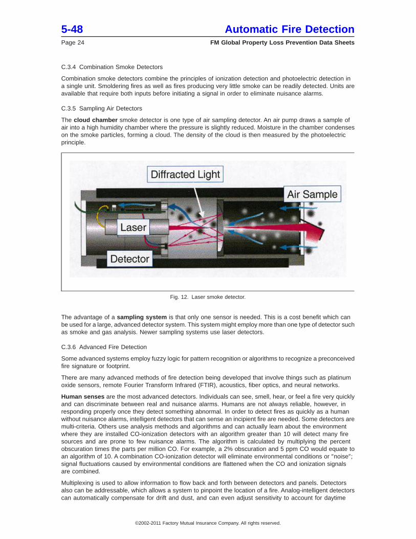
Laser Smoke Detector: Similar to a photoelectric detector except that the light source is a laser, and lightis reflected back to the sensor which is located next to the laser.
5-48 Automatic Fire DetectionPage 16 FM Global Property Loss Prevention Data Sheets
©2002-2011 Factory Mutual Insurance Company. All rights reserved.
Photoelectric Detector: Consists of a light source and a sensor. When smoke enters the chamber, light isscattered and some of the light is redirected to the sensor which is off to the side.
Plume: Thermally-driven flow of products of combustion that rise from a flame.
Power Law Fire: See T-squared fire.
Preaction Sprinkler System: A sprinkler system that is located downstream of a preaction valve and isequipped with closed-type sprinklers (i.e. sprinklers equipped with a thermal sensing element and an orificecap).
Pyrolysis: Chemical change brought about by the action of heat.
Refrigerated Area Systems: Hybrid preaction systems that require both a sprinkler and a heat actuated deviceto operate before the water control valve opens and admits water into the sprinkler piping. They are intendedfor use in freezers with extremely low temperatures.
Response Time Index (RTI): An expression of a heat detector’s sensitivity, used to determine its time constant.
Spot Detector: A fire detector with a small element that senses heat or smoke at its location only. Spotdetectors cover a specified area.
Smoke: Visible and invisible products of incomplete combustion, including solid and liquid particles and gases.Also referred to as aerosols.
Smoldering: Nonflaming combustion, which occurs in char-forming materials where the insulating nature ofthe char traps heat and maintains a glowing reaction zone.
Smooth Ceiling: A smooth ceiling is one where beams project below the ceiling no more than 3% of the ceilingheight.
Stratification: Heat buildup near a ceiling, which can prevent smoke from rising to the ceiling and cause alayer of smoke at a lower elevation.
Supervision: Monitoring an alarm circuit for integrity and fault conditions.
Thermal Lag: The temperature difference of a fixed temperature heat detector element and the air outsidethe element. At detector activation, the air temperature will be higher than that of the element itself.
Threshold Fire Size: The size fire that will be detected within the intended response time.
T-squared fire (t2): A fire where the heat release rate is proportional to the square of the time.
Very Early Warning Fire Detection (VEWFD): Detectors using xenon or laser light detection chambers canbe considered VEWFD detectors. These detectors may be spot-type or air sampling type detection systems.VEWFD detectors are an order of magnitude more sensitive than conventional smoke detectors, and canbe set to alarm at smoke obscuration levels below 0.02%/ft (0.06%/m). Conventional smoke detectors alarmat 1 to 3%/ft (3.3 to 9.8%/m).
Wireless Smoke Detector: A battery-operated device with a radio transmitter for sending information includingpower level to a panel.
APPENDIX B DOCUMENT REVISION HISTORY
January 2011. The following changes were made:
• Updated spacing recommendations for heat detectors using response time index (RTI).
• Added guidelines for new detection technologies.
• Provided detection installation recommendations for preaction sprinkler systems.
• Added testing method and frequency tables.
June 2009. Reference to Data Sheet 7-53, Liquefied Natural Gas (LNG), was deleted.
January 2005. Updated with editorial changes.
May 2003. Recommendation 2.2.2.2.1 was changed to be in agreement with recommendation 2.2.2.2.2 thatcovers the installation of line-type heat detectors.
Automatic Fire Detection 5-48FM Global Property Loss Prevention Data Sheets Page 17
©2002-2011 Factory Mutual Insurance Company. All rights reserved.
May 2002. Sections 2.2.2.2 and 2.2.3.2.1 were changed and are now consistent for heat and smoke detectors.The decision to install detectors on the bottom of beams now depends on the ratios of beam depth and beamspacing to ceiling height. A depth ratio of 0.10 and a spacing ratio of 0.30 has been used.
January 2002. The following changes were made:
1. A Support for Recommendations section has been created with loss experience.
2. A glossary and a reference section have been added.
3. An appendix has been added. Much of the information on detectors from the previous version of the datasheet has been placed in the appendix. New information on detectors and calculation methods for detectorspacing, temperature rise during a fire and stratification have been added. The intent of the calculations isto help minimize response time.
4. New recommendations have been added as follows:
• distances of detectors from walls, corners, etc., have changed from specific distances to percentages ofthe ceiling height (H) above the base of a fire (the ceiling height in most cases).
• applications of various types of detectors.
• additional spacing guidelines.
• how to handle beams, joists and partitions.
• environmental considerations (adverse effects on detectors).
• table for heat detector spacing based on ceiling height.
• table on smoke detector spacing based on room air changes.
5. Information has been added on minimizing nuisance alarms.
APPENDIX C CHARACTERISTICS OF AND APPLICATIONS FOR AUTOMATIC FIRE DETECTORS
C.1 General Information
An automatic fire detector is a device that senses or detects the presence of fire and initiates action. Thefour principal classes of automatic fire detectors are heat detectors, smoke detectors, flame detectors, andfire-gas detectors. Temperature rise, radiation, CO2 (except in a pure hydrogen fire), and H2O are alwaysfound in a flaming fire. Smoke and CO are usually there, but the amount varies greatly depending on the typeof fire. The three principal types of fire detectors are spot detectors, line-type detectors, and air samplingdetectors. A spot-type detector is one in which the sensor is concentrated at a particular location. A line-typedetector is one in which detection is continuous along a path. In an air sampling detector, a pump drawsair from the protected area through a series of tubes to the sensor where it is analyzed for fire products.
The dimensions used to indicate the allowable coverage of the detector are called the spacing. The spacingmay be stated as the horizontal distance between detectors, expressed in feet (meters), or the maximumcoverage, expressed in square feet (square meters). The spacing figure mentioned by recognized testinglaboratories for detectors is an indication of their relative sensitivity. However, detectors operating on variousphysical principles have different sensitivities to different types of fires and fuels. Fires may be fast or slowburning, flaming or smoldering (or pyrolizing).
Also important in a well-designed fire detection system is the elimination of false and nuisance alarms. Falsealarms are caused by things such as electromagnetic fields, dust, excessive heat, and radio frequencyinterference. The elimination of false alarms should be incorporated into the component design. Componentssuch as detectors and panels should be FM Approved or listed by a nationally recognized testing laboratory.In North America, detectors must be compatible with the alarm panel, and must be wired properly accordingto NFPA 72, National Fire Alarm Code, and NFPA 70, National Electrical Code. See Data Sheet 5-40, FireAlarm Systems. Outside North American, adhere to the comparable international standards.
Nuisance alarms can be caused by non-fire sources such as steam, cutting and welding, engine exhaustfumes, dust, lighting, and smoking. Nuisance alarms can be minimized through proper system design,application, installation, maintenance and cleaning, and also by using advanced detectors or systems that candifferentiate between fire and non-fire sources. These things are as important as component design and
5-48 Automatic Fire DetectionPage 18 FM Global Property Loss Prevention Data Sheets
©2002-2011 Factory Mutual Insurance Company. All rights reserved.
are a significant part of total system reliability. Detectors alone can not be blamed for all false alarms. Thereare many other factors that can lead to false and nuisance alarms. Improper wiring, loose connections, andvarious types of faults can lead to false alarms.
C.2 Heat Detectors
C.2.1 Introduction
A heat detector senses abnormally high temperature or rate of temperature rise. Heat detectors can beclassified according to their operating principle as fixed-temperature detectors, rate-compensation detectors,and rate-of-rise detectors. For fixed-temperature and rate-compensation detectors, as long as the temperatureof the fire gases is above the detector rating, heat transferred from the ceiling gas flow to the detector willcause it to actuate when faster response is desired, detectors must be spaced closer than normal.
Rate-of-rise devices may alarm more quickly than fixed-temperature detectors, particularly in highlycombustible occupancies, in unheated buildings in the winter, and in cold storage areas. Note that forrate-of-rise detectors, a false alarm may occur when temporary heaters are used or an interruption ofrefrigeration occurs. Fixed-temperature devices may be more reliable in detecting slowly developing fires, andthey usually require less attention to prevent false alarms.
Heat detectors may employ more than one operating principle in order to respond quickly to both fast-actingand slow-acting fires. Such a unit could be a combination fixed-temperature and rate-of-rise heat detector.The fixed-temperature device in this combination detector operates in case the temperature rises too slowlyto operate the rate-of-rise device.
A non-restorable heat detector has a sensing element that is destroyed when a fire is detected. The sensingelement in a restorable detector is not ordinarily destroyed when a fire is detected. Some detectors areautomatically self-restoring as the sensing element returns to normal.
C.2.2 Fixed-temperature Detectors
The fixed-temperature detector is designed to operate when the temperature of its operating element reachesa predetermined value. Because there is a thermal lag, the temperature of the surrounding air is higher thanthe operating temperature of the detector itself. The fixed-temperature sensing element for a detector mayconsist of two metals having different coefficients of thermal expansion (bimetallic), an electrical resistorwhose resistance varies as a function of temperature (electric conductivity), a special composition metalthat melts quickly at the rated temperature (fusible alloy), two current-carrying wires separated by heatsensitive insulation that softens at the rated temperature so that the wires make electrical contact (heatsensitive cable), or a liquid capable of expansion in response to the increase in temperature (liquid expansion).
C.2.3 Rate-compensation Detectors
The rate-compensation detector is designed to operate when the temperature of the air surrounding thedetector reaches a predetermined value, regardless of the rate of temperature rise. This device is intendedto reduce the effect of thermal lag that is present in a fixed-temperature detector.
C.2.4 Rate-of-rise Detectors
The rate-of-rise detector is designed to operate when the temperature of its operating element rises at arate exceeding a predetermined amount (rate-of-rise set point value), regardless of the temperature level.The rate-of-rise set point is usually between 15°F (8.3°C) and 25°F (13.9°C) rise per minute. These detectorsshould not be used in an area where temperature can change rapidly such as near some machinery. Arate-of-rise detector may be a line-type unit consisting of small diameter pneumatic tubing which is terminatedin a detector unit having calibrated vents, diaphragms, and contacts arranged to actuate at a predeterminedpressure. The detection system is sealed except for the calibrated vents, which compensate for normalchanges in temperature. A rate-of-rise detector can also consist of a spot-type unit with an air chamber,diaphragm, contacts, and vent contained in a single enclosure. A third type of rate-of-rise detector is thethermoelectric effect type. In this type the sensing element consists of a thermocouple or thermopile unit,which produces an increase in electric potential in response to an increase in temperature. An alarm is initiatedwhen the potential increases at an abnormal rate. This type is subject to a lowering of sensitivity by corrosion.
Automatic Fire Detection 5-48FM Global Property Loss Prevention Data Sheets Page 19
©2002-2011 Factory Mutual Insurance Company. All rights reserved.
C.2.5 FM Approved Heat Detectors
An FM Approved heat detector will operate at least as quickly as an FM Approved, comparably degree-rated,automatic sprinkler on 10 by 10 ft (3 by 3 m) spacing under the same conditions of heat exposure. An FMApproved detector is also designed to operate within 3% of its intended fixed temperature in °F or, if of therate-of-rise type, to operate at an ambient temperature increase of between 15°F and 25°F (8.3°C and13.9°C) per minute.
C.3 Smoke Detectors
C.3.1 Introduction
A smoke detector senses visible or invisible particles of combustion. Smoke detectors can be classifiedaccording to their operating principle as ionization detectors, photoelectric detectors, beam detectors, laserdetectors and air sampling detectors. Smoke detectors will usually respond more quickly and to smaller firesthan heat detectors. Care should be taken when applying FM Approved detector spacings because spacingis highly dependent on ceiling height and other factors.
Ceiling height, shape of ceiling, arrangement of contents, burning characteristics of the stored combustibles,ventilation, and environment must be considered when determining the spacing for smoke detectors invarious applications. The expected fire size also is important. To detect a 100 kW fire in the same amountof time as a 1000 kW fire requires that detectors be spaced much closer.
The aerodynamic design of the detector can be important if it restricts smoke entry (see Heskestad, G.,″Generalized Characterization of Smoke Entry and Response for Products-of-Combustion Detectors,″ FireDetection for Life Safety, Proceedings, March 31 to April 1, 1975, National Academy of Sciences, WashingtonD.C., 1977). A characteristic length, L, can be determined for a detector model using a ″smoke box″ approvalapparatus. A characteristic length of 0 ft would mean no restriction to flow.
For a given fire source, tests have shown that, outside the detector, the mass concentration of smoke particlesis approximately proportional to the local temperature rise. So it can be said that a smoke detector respondsto a given temperature rise of the fire gases. This temperature rise depends on the fire source. Thetemperature rise that produces a response is dependent on the specific detector. For some years, 55°F (13°C)has been the benchmark for temperature rise at response. However, this was based on tests done with acertain ionization detector and a wood crib fire. This temperature rise can be either significantly lower, usingcotton for example, in the case of ionization detectors, or significantly higher, using wood cribs for example,in the case of photoelectric detectors. More testing with various combinations of fuels and detector typesis needed to correlate smoke density with local temperature rise.
To obtain a signal from a smoke detector, the smoke must enter the detector unit itself, or the smoke mustinterrupt or obscure a light beam. Although the protected area may appear to be filled with smoke, smokeis sometimes prevented from getting to the detector because of stratification (see Section C.4.), or becauseair currents carry smoke particles away from the detector. Other factors that influence the ability of the smoketo get to the detector in sufficient quantity to activate it are the location of ventilation inlet and exhaustopenings in the protected area, rate of air change, room furnishings, and structural beams or otherobstructions. High air flow (velocity > 300 ft (91 m) per minute) can actually make it difficult for smoke toenter a detector.
The maximum local temperature near the ceiling, and hence smoke concentration, usually occurs about 1%of the ceiling height below the ceiling, and remains near this value to a depth of approximately 5% of theceiling height below the ceiling. The temperature will decrease to near room temperature at about 10% of theceiling height below the ceiling if there is venting of the gases preventing an accumulation at the ceiling.Based on these findings, installing smoke detectors up to 5% of the ceiling height below the ceiling isacceptable.
C.3.2 Ionization Smoke Detectors
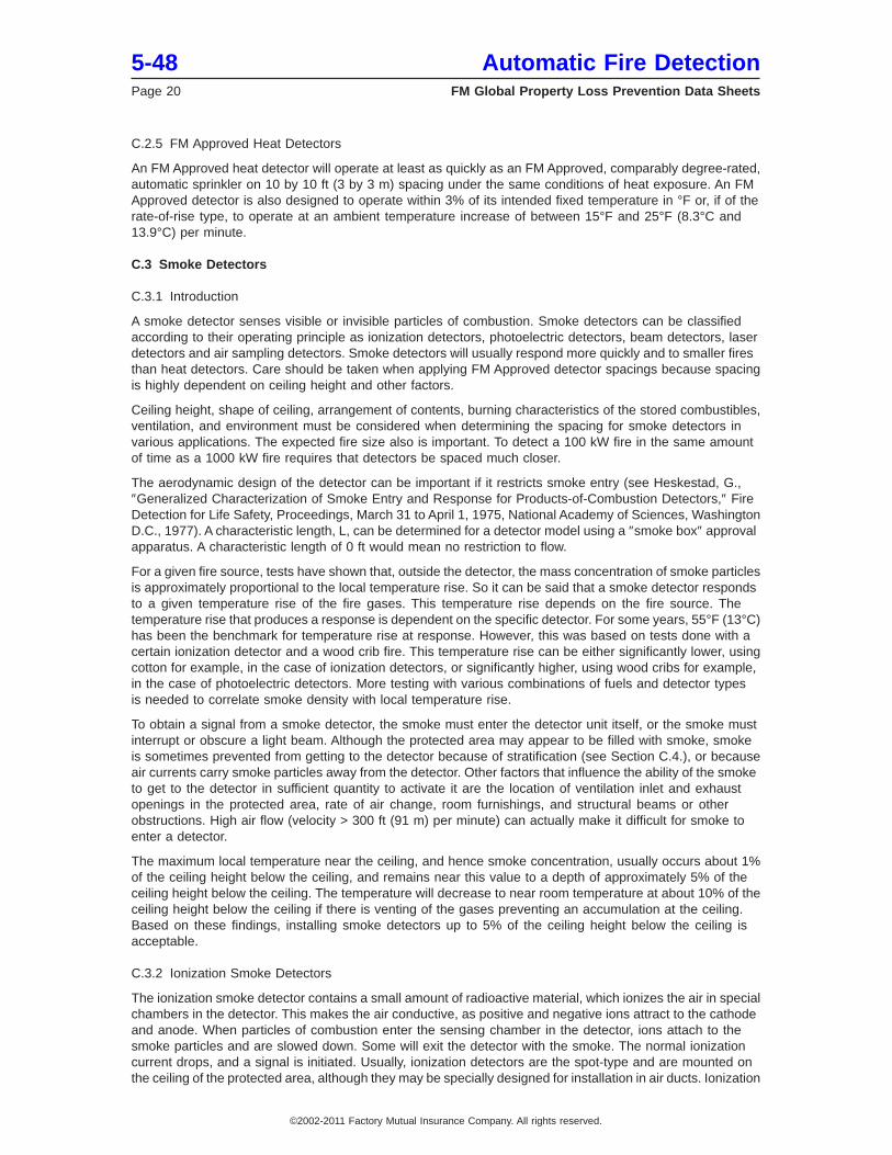
The ionization smoke detector contains a small amount of radioactive material, which ionizes the air in specialchambers in the detector. This makes the air conductive, as positive and negative ions attract to the cathodeand anode. When particles of combustion enter the sensing chamber in the detector, ions attach to thesmoke particles and are slowed down. Some will exit the detector with the smoke. The normal ionizationcurrent drops, and a signal is initiated. Usually, ionization detectors are the spot-type and are mounted onthe ceiling of the protected area, although they may be specially designed for installation in air ducts. Ionization
5-48 Automatic Fire DetectionPage 20 FM Global Property Loss Prevention Data Sheets
©2002-2011 Factory Mutual Insurance Company. All rights reserved.
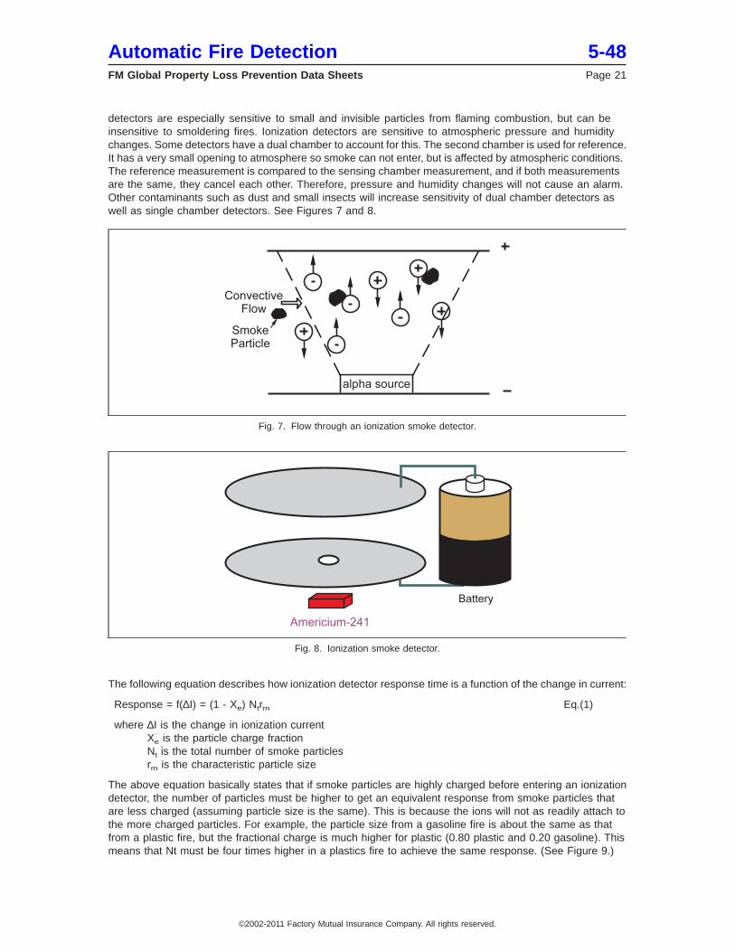
detectors are especially sensitive to small and invisible particles from flaming combustion, but can beinsensitive to smoldering fires. Ionization detectors are sensitive to atmospheric pressure and humiditychanges. Some detectors have a dual chamber to account for this. The second chamber is used for reference.It has a very small opening to atmosphere so smoke can not enter, but is affected by atmospheric conditions.The reference measurement is compared to the sensing chamber measurement, and if both measurementsare the same, they cancel each other. Therefore, pressure and humidity changes will not cause an alarm.Other contaminants such as dust and small insects will increase sensitivity of dual chamber detectors aswell as single chamber detectors. See Figures 7 and 8.
The following equation describes how ionization detector response time is a function of the change in current:
Response = f(∆I) = (1 - Xe) Ntrm Eq.(1)
where ∆I is the change in ionization currentXe is the particle charge fractionNt is the total number of smoke particlesrm is the characteristic particle size
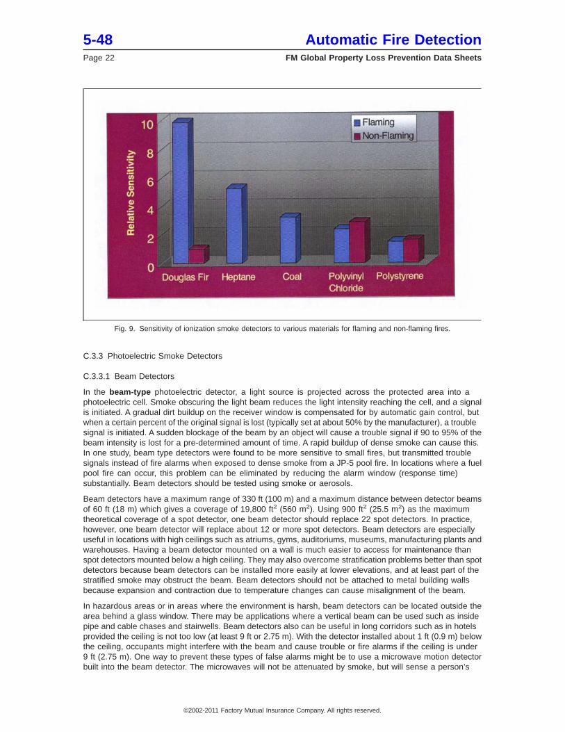
The above equation basically states that if smoke particles are highly charged before entering an ionizationdetector, the number of particles must be higher to get an equivalent response from smoke particles thatare less charged (assuming particle size is the same). This is because the ions will not as readily attach tothe more charged particles. For example, the particle size from a gasoline fire is about the same as thatfrom a plastic fire, but the fractional charge is much higher for plastic (0.80 plastic and 0.20 gasoline). Thismeans that Nt must be four times higher in a plastics fire to achieve the same response. (See Figure 9.)
Fig. 7. Flow through an ionization smoke detector.
Fig. 8. Ionization smoke detector.
Automatic Fire Detection 5-48FM Global Property Loss Prevention Data Sheets Page 21
©2002-2011 Factory Mutual Insurance Company. All rights reserved.
C.3.3 Photoelectric Smoke Detectors
C.3.3.1 Beam Detectors
In the beam-type photoelectric detector, a light source is projected across the protected area into aphotoelectric cell. Smoke obscuring the light beam reduces the light intensity reaching the cell, and a signalis initiated. A gradual dirt buildup on the receiver window is compensated for by automatic gain control, butwhen a certain percent of the original signal is lost (typically set at about 50% by the manufacturer), a troublesignal is initiated. A sudden blockage of the beam by an object will cause a trouble signal if 90 to 95% of thebeam intensity is lost for a pre-determined amount of time. A rapid buildup of dense smoke can cause this.In one study, beam type detectors were found to be more sensitive to small fires, but transmitted troublesignals instead of fire alarms when exposed to dense smoke from a JP-5 pool fire. In locations where a fuelpool fire can occur, this problem can be eliminated by reducing the alarm window (response time)substantially. Beam detectors should be tested using smoke or aerosols.
Beam detectors have a maximum range of 330 ft (100 m) and a maximum distance between detector beamsof 60 ft (18 m) which gives a coverage of 19,800 ft2 (560 m2). Using 900 ft2 (25.5 m2) as the maximumtheoretical coverage of a spot detector, one beam detector should replace 22 spot detectors. In practice,however, one beam detector will replace about 12 or more spot detectors. Beam detectors are especiallyuseful in locations with high ceilings such as atriums, gyms, auditoriums, museums, manufacturing plants andwarehouses. Having a beam detector mounted on a wall is much easier to access for maintenance thanspot detectors mounted below a high ceiling. They may also overcome stratification problems better than spotdetectors because beam detectors can be installed more easily at lower elevations, and at least part of thestratified smoke may obstruct the beam. Beam detectors should not be attached to metal building wallsbecause expansion and contraction due to temperature changes can cause misalignment of the beam.
In hazardous areas or in areas where the environment is harsh, beam detectors can be located outside thearea behind a glass window. There may be applications where a vertical beam can be used such as insidepipe and cable chases and stairwells. Beam detectors also can be useful in long corridors such as in hotelsprovided the ceiling is not too low (at least 9 ft or 2.75 m). With the detector installed about 1 ft (0.9 m) belowthe ceiling, occupants might interfere with the beam and cause trouble or fire alarms if the ceiling is under9 ft (2.75 m). One way to prevent these types of false alarms might be to use a microwave motion detectorbuilt into the beam detector. The microwaves will not be attenuated by smoke, but will sense a person’s
Fig. 9. Sensitivity of ionization smoke detectors to various materials for flaming and non-flaming fires.
5-48 Automatic Fire DetectionPage 22 FM Global Property Loss Prevention Data Sheets
©2002-2011 Factory Mutual Insurance Company. All rights reserved.
motion. If both detectors sense something at the same time, then an alarm output would be delayed. Somebeam detector models monitor the beam wave frequency and thus can also sense heat which attenuatesthe beam.
C.3.3.2 Photoelectric Spot Detectors
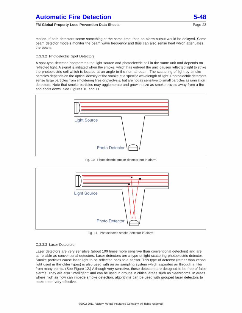
A spot-type detector incorporates the light source and photoelectric cell in the same unit and depends onreflected light. A signal is initiated when the smoke, which has entered the unit, causes reflected light to strikethe photoelectric cell which is located at an angle to the normal beam. The scattering of light by smokeparticles depends on the optical density of the smoke at a specific wavelength of light. Photoelectric detectorssense large particles from smoldering fires or pyrolysis, but are not as sensitive to small particles as ionizationdetectors. Note that smoke particles may agglomerate and grow in size as smoke travels away from a fireand cools down. See Figures 10 and 11.
C.3.3.3 Laser Detectors
Laser detectors are very sensitive (about 100 times more sensitive than conventional detectors) and areas reliable as conventional detectors. Laser detectors are a type of light-scattering photoelectric detector.Smoke particles cause laser light to be reflected back to a sensor. This type of detector (rather than xenonlight used in the older types) is also used with an air sampling system which aspirates air through a filterfrom many points. (See Figure 12.) Although very sensitive, these detectors are designed to be free of falsealarms. They are also ″intelligent″ and can be used in groups in critical areas such as cleanrooms. In areaswhere high air flow can impede smoke detection, algorithms can be used with grouped laser detectors tomake them very effective.
Fig. 10. Photoelectric smoke detector not in alarm.
Fig. 11. Photoelectric smoke detector in alarm.
Automatic Fire Detection 5-48FM Global Property Loss Prevention Data Sheets Page 23
©2002-2011 Factory Mutual Insurance Company. All rights reserved.
C.3.4 Combination Smoke Detectors
Combination smoke detectors combine the principles of ionization detection and photoelectric detection ina single unit. Smoldering fires as well as fires producing very little smoke can be readily detected. Units areavailable that require both inputs before initiating a signal in order to eliminate nuisance alarms.
C.3.5 Sampling Air Detectors
The cloud chamber smoke detector is one type of air sampling detector. An air pump draws a sample ofair into a high humidity chamber where the pressure is slightly reduced. Moisture in the chamber condenseson the smoke particles, forming a cloud. The density of the cloud is then measured by the photoelectricprinciple.
The advantage of a sampling system is that only one sensor is needed. This is a cost benefit which canbe used for a large, advanced detector system. This system might employ more than one type of detector suchas smoke and gas analysis. Newer sampling systems use laser detectors.
C.3.6 Advanced Fire Detection
Some advanced systems employ fuzzy logic for pattern recognition or algorithms to recognize a preconceivedfire signature or footprint.
There are many advanced methods of fire detection being developed that involve things such as platinumoxide sensors, remote Fourier Transform Infrared (FTIR), acoustics, fiber optics, and neural networks.
Human senses are the most advanced detectors. Individuals can see, smell, hear, or feel a fire very quicklyand can discriminate between real and nuisance alarms. Humans are not always reliable, however, inresponding properly once they detect something abnormal. In order to detect fires as quickly as a humanwithout nuisance alarms, intelligent detectors that can sense an incipient fire are needed. Some detectors aremulti-criteria. Others use analysis methods and algorithms and can actually learn about the environmentwhere they are installed CO-ionization detectors with an algorithm greater than 10 will detect many firesources and are prone to few nuisance alarms. The algorithm is calculated by multiplying the percentobscuration times the parts per million CO. For example, a 2% obscuration and 5 ppm CO would equate toan algorithm of 10. A combination CO-ionization detector will eliminate environmental conditions or ″noise″;signal fluctuations caused by environmental conditions are flattened when the CO and ionization signalsare combined.
Multiplexing is used to allow information to flow back and forth between detectors and panels. Detectorsalso can be addressable, which allows a system to pinpoint the location of a fire. Analog-intelligent detectorscan automatically compensate for drift and dust, and can even adjust sensitivity to account for daytime
Fig. 12. Laser smoke detector.
5-48 Automatic Fire DetectionPage 24 FM Global Property Loss Prevention Data Sheets
©2002-2011 Factory Mutual Insurance Company. All rights reserved.
activities such as smoking or welding. Programming intelligent systems is very important to reliable operation.When changes are made, testing should be performed to verify that the program is error-free and performsas intended. A listed Compare Program should be used to verify changes. Some fire alarm panelmanufacturers provide Compare Programs that compare the original program with the new one and showsthe changes that were made.
Alarm verification or cross-zoning can be used in fire alarm systems to minimize nuisance alarms. SeeData Sheet 5-40, Fire Alarm Systems, for information on these two methods.
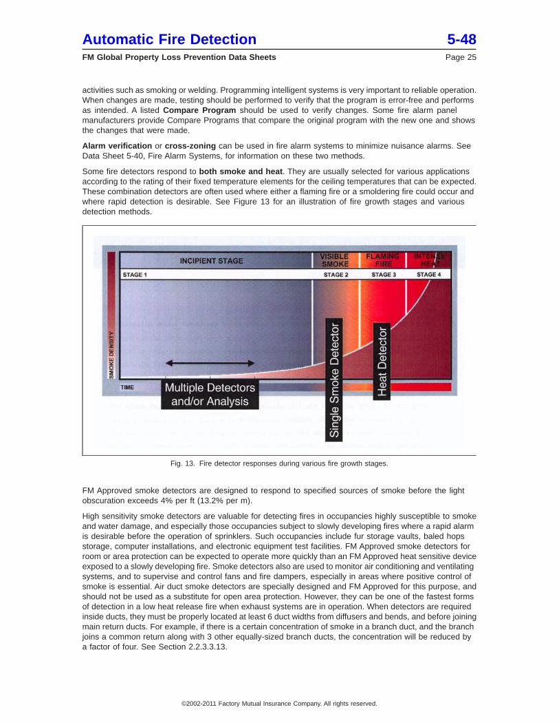
Some fire detectors respond to both smoke and heat. They are usually selected for various applicationsaccording to the rating of their fixed temperature elements for the ceiling temperatures that can be expected.These combination detectors are often used where either a flaming fire or a smoldering fire could occur andwhere rapid detection is desirable. See Figure 13 for an illustration of fire growth stages and variousdetection methods.
FM Approved smoke detectors are designed to respond to specified sources of smoke before the lightobscuration exceeds 4% per ft (13.2% per m).
High sensitivity smoke detectors are valuable for detecting fires in occupancies highly susceptible to smokeand water damage, and especially those occupancies subject to slowly developing fires where a rapid alarmis desirable before the operation of sprinklers. Such occupancies include fur storage vaults, baled hopsstorage, computer installations, and electronic equipment test facilities. FM Approved smoke detectors forroom or area protection can be expected to operate more quickly than an FM Approved heat sensitive deviceexposed to a slowly developing fire. Smoke detectors also are used to monitor air conditioning and ventilatingsystems, and to supervise and control fans and fire dampers, especially in areas where positive control ofsmoke is essential. Air duct smoke detectors are specially designed and FM Approved for this purpose, andshould not be used as a substitute for open area protection. However, they can be one of the fastest formsof detection in a low heat release fire when exhaust systems are in operation. When detectors are requiredinside ducts, they must be properly located at least 6 duct widths from diffusers and bends, and before joiningmain return ducts. For example, if there is a certain concentration of smoke in a branch duct, and the branchjoins a common return along with 3 other equally-sized branch ducts, the concentration will be reduced bya factor of four. See Section 2.2.3.3.13.
Fig. 13. Fire detector responses during various fire growth stages.
Automatic Fire Detection 5-48FM Global Property Loss Prevention Data Sheets Page 25
©2002-2011 Factory Mutual Insurance Company. All rights reserved.
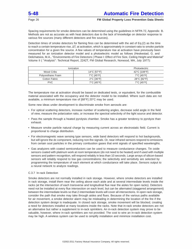
Spacing requirements for smoke detectors can be determined using the guidelines in NFPA 72, Appendix B.Methods are not as accurate as with heat detectors due to the lack of knowledge on detector response tovarious fire sources (many different detectors and fire sources).
Detection times of smoke detectors for flaming fires can be determined with the aid of Eq.(2) as the timeto reach a certain temperature rise, ∆T, at activation, which is approximately in constant ratio to smoke particleconcentration for a given fire source. A few values of temperature rise at activation have previously beenmeasured for an ionization detector model and a photoelectric model as follows (Heskestad, G. andDelichatsios, M.A., ″Environments of Fire Detectors ( Phase I: Effect of Fire Size, Ceiling Height and Material″Volume II ( ″Analysis″: Technical Report, 2242T, FM Global Research, Norwood, MA, July 1977):
Ionization PhotoelectricWood Cribs 14°C [57°F] 42°C [108°F]
Polyurethane Foam 7°C [45°F] 7°C [45°F]Cotton Fabric 2°C [36°F] 28°C [82°F]
PVC 7°C [45°F] 7°C [45°F]
The temperature rise at activation should be based on dedicated tests, or equivalent, for the combustiblematerial associated with the occupancy and the detector model to be installed. Where such data are notavailable, a minimum temperature rise of [68°F] 20°C may be used.
Some new ideas under development to discriminate smoke from aerosols are:
• For optical scattering detectors, increase number of scattering angles, decrease solid angle in the fieldof view, measure the polarization ratio, or increase the spectral selectivity of the light source and detector.
• Pass the sample through a heated pyrolysis chamber. Smoke has a greater tendency to pyrolyze thanexhaust.
• Measure smoke particle natural charge by measuring current across an electrostatic field. Current isproportional to charge distribution.
• For electromagnetic wave sensing type sensors, wide band detectors will respond to hot backgrounds,but will ignore the dc component, reducing non-fire signals. Or, near infrared sensors respond to emissionsfrom certain soot particles in the primary combustion gases that emit signals of specified wavelengths.
• Gas analyzers with coated semiconductors can be used to measure conductance changes. Tin oxidesensors coated with platinum work at room temperature (do not need to be heated) and if used with multiplesensors and pattern recognition, will respond reliably in less than 10 seconds. Large arrays of silicon-basedsensors will reliably respond to low gas concentrations; the selectivity and sensitivity are selected byprogramming the temperature of each element at which conductance will take place. Sensors output toa neural network to analyze readings.
C.3.7 In-rack Detection
Smoke detectors are not normally installed in rack storage. However, where smoke detectors are installedin rack storage, install them near the ceiling above each aisle and at several intermediate levels inside theracks (at the intersection of each transverse and longitudinal flue near the aisles for open racks). Detectorsneed not be installed at every flue intersection on each level, but can be alternated (staggered arrangement)between the intermediate levels so that 2 intermediate levels will cover all intersections. In open rack storage,consider the path that smoke may take through aisles and flues. Because of the various paths availablefor air movement, a smoke detector alarm may be misleading in determining the location of the fire if thedetection system design is inadequate. In closed rack storage, smoke movement will be blocked, creatinga need for detectors installed at many locations inside the racks. Note that in-rack smoke detectors are notan alternative but rather a supplement to in-rack sprinklers. An in-rack detection system may prove to bevaluable, however, where in-rack sprinklers are not provided. The cost to wire an in-rack detection systemmay be high. A wireless system can be used to simplify installation and minimize installation cost.
5-48 Automatic Fire DetectionPage 26 FM Global Property Loss Prevention Data Sheets
©2002-2011 Factory Mutual Insurance Company. All rights reserved.
C.4 Effects of Temperature Stratification
If the ambient temperature varies with height in a building space, the operation of fire detectors mountedunder the ceiling may be delayed, which is explained as follows. As the buoyant, turbulent plume rises froma fire, it is cooled by entraining ambient air. The temperature difference between the plume and the ambientair, which gives the plume buoyancy, may vanish and actually reverse sign. Eventually the plume ceasesto rise, and plume fluid moves out radially to eventually form a more or less horizontal layer. The critical valueof ambient temperature rise, from the base of the fire to the ceiling, can be calculated from (Heskestad, G.,Fire Plume Behavior in Temperature-Stratified Spaces, J.I 0Q4E2.RU(3), FM Global Research, Norwood,MA, November 1993; Heskestad, G., Note on Maximum Rise of Fire Plumes in Temperature-StratifiedAmbients, Fire Safety Journal, Vol 15, 1989, p2.):
∆Ta = 190Q2/3 H-5/3 Eq.(2)
(∆T in °C, Q in kW, H in m)
Alternatively, if the ambient temperature rise is known, the minimum heat release rate to drive plume fluidto the ceiling can be calculated from:
Q = [ ∆TaH5/3 /190 ] 3/2Eq.(3)
For example, if the ceiling height is 10 m (33 ft) and the ambient temperature rise to the ceiling is 5°C (9°F),the minimum heat release rate to drive plume fluid to the ceiling is 1.3 kW (74 Btu/min) (using Eq. 3), theapproximate equivalent of a 7 cm (2.75 in.) diameter methanol fire. For a 20 m (66 ft) ceiling height and a10°C (18°F) ambient temperature rise, the minimum heat release rate is 22 kW (1252 Btu/min), theapproximate equivalent of a 0.30 m (1 ft) diameter methanol fire.
If the ambient temperature rise is less than the critical value for the fire size at a given moment, plume fluidwill spread under the ceiling. If the ambient temperature rise is less than approximately 0.3 times the criticalambient temperature rise, there is little effect of the stratification on the ceiling flow. In the intermediate rangethere is a significant effect.
Estimates have indicated that there could be a significant increase in fire size at response of a heat detectorin a growing fire, due to stratification. In a particular example of a ceiling mounted fixed temperature detectoroperating at a local gas temperature rise of 63°F (35°C) and an ambient temperature rise from floor to ceilingof 22°F (12°C), a 40% increase in fire size at detection can be expected due to the stratification. For a weakerstratification, corresponding to 9°F ambient temperature rise at the ceiling level, the estimated increase infire size is 15%.
It has been estimated that if temperature stratification were to be a factor in the response of smoke detectorsthat respond near a temperature rise of 18°F (10°C) in a uniform ambient, the ambient temperature rise atthe ceiling would have to be greater than 68°F (38°C). This is very high and not likely to be encountered in thefield.
Smoke detectors of very high sensitivity have entered the market, and an equivalent temperature rise atdetection of 1°C (1.8°F) is possible. If temperature stratification were to be a factor in these cases, the ambienttemperature rise at the ceiling would have to be greater than about 4°C (7°F), which clearly is not uncommon.Unless a detector happens to be fairly close to a fire, detection will probably be delayed in many practicalcases.
C.5 Flame Detectors
A flame detector is sensitive to infrared, visible, or ultraviolet radiation produced by a fire, or to specific rangesof radiation that are modulated at characteristic flame flicker frequencies.
Flame detectors are essentially line-of-sight devices, and are usually designed to respond to a fire withinthe detector’s cone of vision in approximately one second or less. The maximum response time of FMApproved detectors is 30 seconds. Depending on the combination of the fuel and frequency range of thedetector, it is possible to have no response to a fire.
The infrared detector contains a sensing element that is responsive to radiant energy at wavelengths belowthe range of human vision. This is usually above approximately 7700 Angstroms. A very high speed infrareddetector that senses a portion of the infrared energy of flame is available. This device responds in less than5 milliseconds to produce a voltage sufficient to release an extinguishing agent and sound an alarm. Normally,the device is used to actuate an external explosive-operated release to discharge water or other extinguishing
Automatic Fire Detection 5-48FM Global Property Loss Prevention Data Sheets Page 27
©2002-2011 Factory Mutual Insurance Company. All rights reserved.
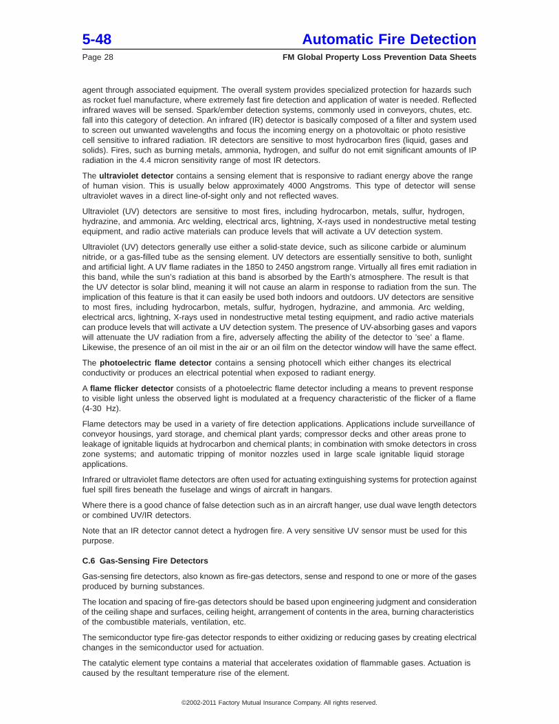
agent through associated equipment. The overall system provides specialized protection for hazards suchas rocket fuel manufacture, where extremely fast fire detection and application of water is needed. Reflectedinfrared waves will be sensed. Spark/ember detection systems, commonly used in conveyors, chutes, etc.fall into this category of detection. An infrared (IR) detector is basically composed of a filter and system usedto screen out unwanted wavelengths and focus the incoming energy on a photovoltaic or photo resistivecell sensitive to infrared radiation. IR detectors are sensitive to most hydrocarbon fires (liquid, gases andsolids). Fires, such as burning metals, ammonia, hydrogen, and sulfur do not emit significant amounts of IPradiation in the 4.4 micron sensitivity range of most IR detectors.
The ultraviolet detector contains a sensing element that is responsive to radiant energy above the rangeof human vision. This is usually below approximately 4000 Angstroms. This type of detector will senseultraviolet waves in a direct line-of-sight only and not reflected waves.
Ultraviolet (UV) detectors are sensitive to most fires, including hydrocarbon, metals, sulfur, hydrogen,hydrazine, and ammonia. Arc welding, electrical arcs, lightning, X-rays used in nondestructive metal testingequipment, and radio active materials can produce levels that will activate a UV detection system.
Ultraviolet (UV) detectors generally use either a solid-state device, such as silicone carbide or aluminumnitride, or a gas-filled tube as the sensing element. UV detectors are essentially sensitive to both, sunlightand artificial light. A UV flame radiates in the 1850 to 2450 angstrom range. Virtually all fires emit radiation inthis band, while the sun’s radiation at this band is absorbed by the Earth’s atmosphere. The result is thatthe UV detector is solar blind, meaning it will not cause an alarm in response to radiation from the sun. Theimplication of this feature is that it can easily be used both indoors and outdoors. UV detectors are sensitiveto most fires, including hydrocarbon, metals, sulfur, hydrogen, hydrazine, and ammonia. Arc welding,electrical arcs, lightning, X-rays used in nondestructive metal testing equipment, and radio active materialscan produce levels that will activate a UV detection system. The presence of UV-absorbing gases and vaporswill attenuate the UV radiation from a fire, adversely affecting the ability of the detector to ’see’ a flame.Likewise, the presence of an oil mist in the air or an oil film on the detector window will have the same effect.
The photoelectric flame detector contains a sensing photocell which either changes its electricalconductivity or produces an electrical potential when exposed to radiant energy.
A flame flicker detector consists of a photoelectric flame detector including a means to prevent responseto visible light unless the observed light is modulated at a frequency characteristic of the flicker of a flame(4-30 Hz).
Flame detectors may be used in a variety of fire detection applications. Applications include surveillance ofconveyor housings, yard storage, and chemical plant yards; compressor decks and other areas prone toleakage of ignitable liquids at hydrocarbon and chemical plants; in combination with smoke detectors in crosszone systems; and automatic tripping of monitor nozzles used in large scale ignitable liquid storageapplications.
Infrared or ultraviolet flame detectors are often used for actuating extinguishing systems for protection againstfuel spill fires beneath the fuselage and wings of aircraft in hangars.
Where there is a good chance of false detection such as in an aircraft hanger, use dual wave length detectorsor combined UV/IR detectors.
Note that an IR detector cannot detect a hydrogen fire. A very sensitive UV sensor must be used for thispurpose.
C.6 Gas-Sensing Fire Detectors
Gas-sensing fire detectors, also known as fire-gas detectors, sense and respond to one or more of the gasesproduced by burning substances.
The location and spacing of fire-gas detectors should be based upon engineering judgment and considerationof the ceiling shape and surfaces, ceiling height, arrangement of contents in the area, burning characteristicsof the combustible materials, ventilation, etc.
The semiconductor type fire-gas detector responds to either oxidizing or reducing gases by creating electricalchanges in the semiconductor used for actuation.
The catalytic element type contains a material that accelerates oxidation of flammable gases. Actuation iscaused by the resultant temperature rise of the element.
5-48 Automatic Fire DetectionPage 28 FM Global Property Loss Prevention Data Sheets
©2002-2011 Factory Mutual Insurance Company. All rights reserved.
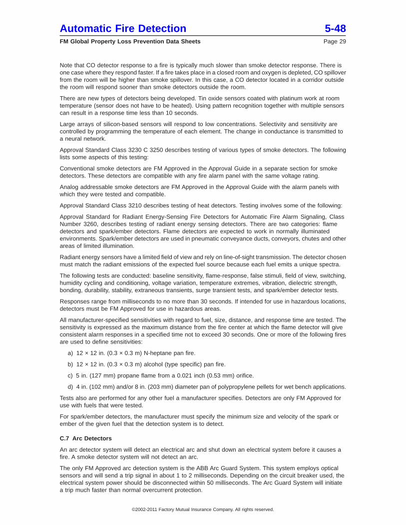
Note that CO detector response to a fire is typically much slower than smoke detector response. There isone case where they respond faster. If a fire takes place in a closed room and oxygen is depleted, CO spilloverfrom the room will be higher than smoke spillover. In this case, a CO detector located in a corridor outsidethe room will respond sooner than smoke detectors outside the room.
There are new types of detectors being developed. Tin oxide sensors coated with platinum work at roomtemperature (sensor does not have to be heated). Using pattern recognition together with multiple sensorscan result in a response time less than 10 seconds.
Large arrays of silicon-based sensors will respond to low concentrations. Selectivity and sensitivity arecontrolled by programming the temperature of each element. The change in conductance is transmitted toa neural network.
Approval Standard Class 3230 C 3250 describes testing of various types of smoke detectors. The followinglists some aspects of this testing:
Conventional smoke detectors are FM Approved in the Approval Guide in a separate section for smokedetectors. These detectors are compatible with any fire alarm panel with the same voltage rating.
Analog addressable smoke detectors are FM Approved in the Approval Guide with the alarm panels withwhich they were tested and compatible.
Approval Standard Class 3210 describes testing of heat detectors. Testing involves some of the following:
Approval Standard for Radiant Energy-Sensing Fire Detectors for Automatic Fire Alarm Signaling, ClassNumber 3260, describes testing of radiant energy sensing detectors. There are two categories: flamedetectors and spark/ember detectors. Flame detectors are expected to work in normally illuminatedenvironments. Spark/ember detectors are used in pneumatic conveyance ducts, conveyors, chutes and otherareas of limited illumination.
Radiant energy sensors have a limited field of view and rely on line-of-sight transmission. The detector chosenmust match the radiant emissions of the expected fuel source because each fuel emits a unique spectra.
The following tests are conducted: baseline sensitivity, flame-response, false stimuli, field of view, switching,humidity cycling and conditioning, voltage variation, temperature extremes, vibration, dielectric strength,bonding, durability, stability, extraneous transients, surge transient tests, and spark/ember detector tests.
Responses range from milliseconds to no more than 30 seconds. If intended for use in hazardous locations,detectors must be FM Approved for use in hazardous areas.
All manufacturer-specified sensitivities with regard to fuel, size, distance, and response time are tested. Thesensitivity is expressed as the maximum distance from the fire center at which the flame detector will giveconsistent alarm responses in a specified time not to exceed 30 seconds. One or more of the following firesare used to define sensitivities:
a) 12 × 12 in. (0.3 × 0.3 m) N-heptane pan fire.
b) 12 × 12 in. (0.3 × 0.3 m) alcohol (type specific) pan fire.
c) 5 in. (127 mm) propane flame from a 0.021 inch (0.53 mm) orifice.
d) 4 in. (102 mm) and/or 8 in. (203 mm) diameter pan of polypropylene pellets for wet bench applications.
Tests also are performed for any other fuel a manufacturer specifies. Detectors are only FM Approved foruse with fuels that were tested.
For spark/ember detectors, the manufacturer must specify the minimum size and velocity of the spark orember of the given fuel that the detection system is to detect.
C.7 Arc Detectors
An arc detector system will detect an electrical arc and shut down an electrical system before it causes afire. A smoke detector system will not detect an arc.
The only FM Approved arc detection system is the ABB Arc Guard System. This system employs opticalsensors and will send a trip signal in about 1 to 2 milliseconds. Depending on the circuit breaker used, theelectrical system power should be disconnected within 50 milliseconds. The Arc Guard System will initiatea trip much faster than normal overcurrent protection.
Automatic Fire Detection 5-48FM Global Property Loss Prevention Data Sheets Page 29
©2002-2011 Factory Mutual Insurance Company. All rights reserved.
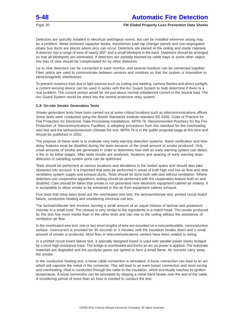
Detectors are typically installed in electrical switchgear rooms, but can be installed wherever arcing maybe a problem. Metal enclosed capacitor banks, transformer load tap changer panels and non-segregatedphase bus ducts are places where arcs can occur. Detectors are placed at the ceiling and inside cabinets.A detector has a range of view of nearly 360° and a small blindspot in the back. Detectors should be arrangedso that all blindspots are eliminated. If detectors are partially blocked by cable trays or some other object,this loss of view should be compensated for by other detectors.
Up to nine detectors can be connected to each monitor, and several monitors can be connected together.Fiber optics are used to communicate between sensors and monitors so that the system is insensitive toelectromagnetic interference.
To prevent nuisance trips due to light sources such as cutting and welding, camera flashes and direct sunlight,a current-sensing device can be used in series with the Arc Guard System to help determine if there is areal problem. The current sensor would be set just above normal unbalanced current in the neutral lead. TheArc Guard System would be wired into the normal protective relay system.
C.8 On-site Smoke Generation Tests
Smoke generation tests have been carried out at some critical locations such as telecommunications offices.Some tests were conducted using the British Standards Institute standard BS 6266, Code of Practice forFire Protection for Electronic Data Processing Installations. NFPA 76, Recommended Practices for the FireProtection of Telecommunications Facilities, is adopting procedures from this standard for the overheatingwire test and the lactose/potassium chlorate fire test. NFPA 76 is in the public proposal stage at this time andshould be published in 2002.
The purpose of these tests is to evaluate very early warning detection systems. Alarm verification and timedelay features must be disabled during the tests because of the small amount of smoke produced. Onlysmall amounts of smoke are generated in order to determine how well an early warning system can detecta fire in its initial stages. After tests results are analyzed, locations and spacing of early warning laserdetectors or sampling system ports can be optimized.
Tests should be performed at various locations and elevations in the tested space and should also takeobstacles into account. It is important that tests be performed in areas of both high and low air flow and nearventilation system supply and exhaust ducts. Tests should be done both with and without ventilation. Wheredetectors use cooperative algorithms, testing should be performed with the cooperation feature both on anddisabled. Care should be taken that smoke is not generated near electronic equipment cabinet air intakes. Itis acceptable to allow smoke to be entrained in the air from equipment cabinet exhaust.
Five tests that have been done are the overheated wire test, the lactose/chlorate test, printed circuit boardfailure, conductive heating and smoldering electrical coil test.
The lactose/chlorate test involves burning a small amount of an equal mixture of lactose and potassiumchlorate in a small bowl. The mixture is very similar to the ingredients in a match head. The smoke producedby this test has more inertia than in the other tests and can rise to the ceiling without the assistance ofventilation air flow.
In the overheated wire test, one or two short lengths of wire are mounted on a noncombustible, nonconductivesurface. Overcurrent is provided for 30 seconds to 3 minutes until the insulation breaks down and a smallamount of smoke is produced. Most fires in telecommunications centers have been related to wiring.
In a printed circuit board failure test, a specially designed board is used with parallel power tracks bridgedby a short high resistance track. The bridge is overheated and forms an arc as power is applied. The substratematerials are degraded and the pyrolysis gases are ignited to form a small flame. Air currents carry awaythe smoke.
In the conductive heating test, a loose cable connection is simulated. A loose connection can lead to an arcwhich will vaporize the metal in the connector. This will lead to an even looser connection and more arcingand overheating. Heat is conducted through the cable to the insulation, which eventually reaches its ignitiontemperature. A loose connection can be simulated by slipping a metal band heater over the end of the cable.A smoldering period of more than an hour is needed to conduct the test.
5-48 Automatic Fire DetectionPage 30 FM Global Property Loss Prevention Data Sheets
©2002-2011 Factory Mutual Insurance Company. All rights reserved.
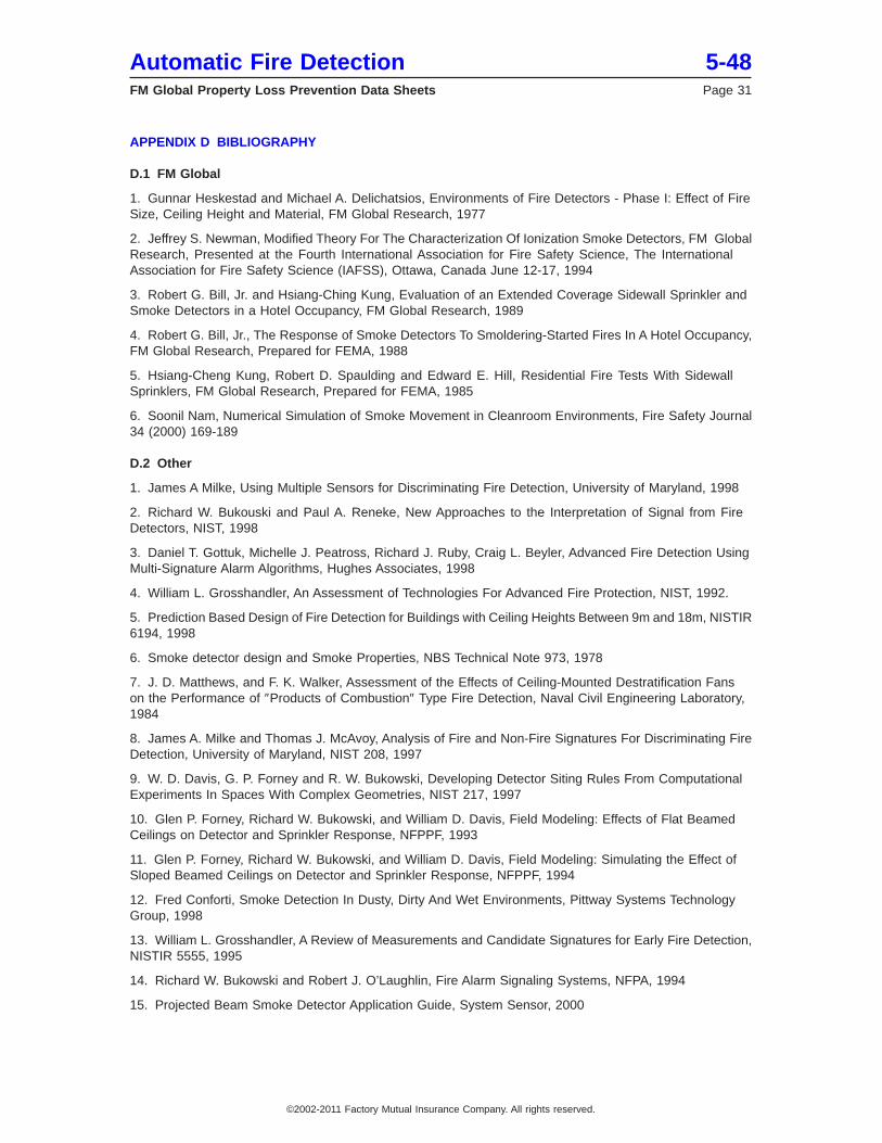
APPENDIX D BIBLIOGRAPHY
D.1 FM Global
1. Gunnar Heskestad and Michael A. Delichatsios, Environments of Fire Detectors - Phase I: Effect of FireSize, Ceiling Height and Material, FM Global Research, 1977
2. Jeffrey S. Newman, Modified Theory For The Characterization Of Ionization Smoke Detectors, FM GlobalResearch, Presented at the Fourth International Association for Fire Safety Science, The InternationalAssociation for Fire Safety Science (IAFSS), Ottawa, Canada June 12-17, 1994
3. Robert G. Bill, Jr. and Hsiang-Ching Kung, Evaluation of an Extended Coverage Sidewall Sprinkler andSmoke Detectors in a Hotel Occupancy, FM Global Research, 1989
4. Robert G. Bill, Jr., The Response of Smoke Detectors To Smoldering-Started Fires In A Hotel Occupancy,FM Global Research, Prepared for FEMA, 1988
5. Hsiang-Cheng Kung, Robert D. Spaulding and Edward E. Hill, Residential Fire Tests With SidewallSprinklers, FM Global Research, Prepared for FEMA, 1985
6. Soonil Nam, Numerical Simulation of Smoke Movement in Cleanroom Environments, Fire Safety Journal34 (2000) 169-189
D.2 Other
1. James A Milke, Using Multiple Sensors for Discriminating Fire Detection, University of Maryland, 1998
2. Richard W. Bukouski and Paul A. Reneke, New Approaches to the Interpretation of Signal from FireDetectors, NIST, 1998
3. Daniel T. Gottuk, Michelle J. Peatross, Richard J. Ruby, Craig L. Beyler, Advanced Fire Detection UsingMulti-Signature Alarm Algorithms, Hughes Associates, 1998
4. William L. Grosshandler, An Assessment of Technologies For Advanced Fire Protection, NIST, 1992.
5. Prediction Based Design of Fire Detection for Buildings with Ceiling Heights Between 9m and 18m, NISTIR6194, 1998
6. Smoke detector design and Smoke Properties, NBS Technical Note 973, 1978
7. J. D. Matthews, and F. K. Walker, Assessment of the Effects of Ceiling-Mounted Destratification Fanson the Performance of ″Products of Combustion″ Type Fire Detection, Naval Civil Engineering Laboratory,1984
8. James A. Milke and Thomas J. McAvoy, Analysis of Fire and Non-Fire Signatures For Discriminating FireDetection, University of Maryland, NIST 208, 1997
9. W. D. Davis, G. P. Forney and R. W. Bukowski, Developing Detector Siting Rules From ComputationalExperiments In Spaces With Complex Geometries, NIST 217, 1997
10. Glen P. Forney, Richard W. Bukowski, and William D. Davis, Field Modeling: Effects of Flat BeamedCeilings on Detector and Sprinkler Response, NFPPF, 1993
11. Glen P. Forney, Richard W. Bukowski, and William D. Davis, Field Modeling: Simulating the Effect ofSloped Beamed Ceilings on Detector and Sprinkler Response, NFPPF, 1994
12. Fred Conforti, Smoke Detection In Dusty, Dirty And Wet Environments, Pittway Systems TechnologyGroup, 1998
13. William L. Grosshandler, A Review of Measurements and Candidate Signatures for Early Fire Detection,NISTIR 5555, 1995
14. Richard W. Bukowski and Robert J. O’Laughlin, Fire Alarm Signaling Systems, NFPA, 1994
15. Projected Beam Smoke Detector Application Guide, System Sensor, 2000
Automatic Fire Detection 5-48FM Global Property Loss Prevention Data Sheets Page 31
©2002-2011 Factory Mutual Insurance Company. All rights reserved.