Embed Size (px)
Citation preview

MOTOR FM7/FM9
Installation manual
Ref.1707

Responsibility exemption
The information described in this manual may be subject to changes dueto technical modifications. Fagor Automation S. Coop. reserves the rightto change the contents of this manual without prior notice.
The content of this manual and its validity for the product described herehas been verified. Nevertheless, the information, technical or otherwise,in these manuals or in any other type of documentation is not guaranteedto be integral, sufficient or up to date.
Involuntary errors are possible, hence the absolute match is guaranteed.However, the contents of manuals and documents are regularly checkedand updated implementing the pertinent corrections in later editions.
Fagor Automation S. Coop. will not be held responsible for any lossesor damage, direct, indirect or by chance that could result from thatinformation and it will be the user's responsibility to use it.
Responsibility and warranty claims are excluded in case of shippingdamage, wrong usage of the unit in wrong environments or when notused for the purpose for which it has been designed, ignoring the war-
nings and safety indications given in this document and/or legal onesthat may be applied to the work place, software modifications and/orrepairs made by unauthorized personnel, damage caused by theinfluence of other nearby equipment.
Warranty
The warranty terms may be requested from your Fagor Automationrepresentative or through the usual commercial channels. The warrantyconditions are available in the downloads section of FAGOR’s corporatewebsite at http://www.fagorautomation.com. ·type of file: Generalterms and conditions of purchase - warranty·.
Registered trademarks
All registered trade marks, even those not indicated are alsoacknowledged. When some are not indicated, it does not mean thatthey are free.
July 2017 / Ref.1707
All rights reserved. No part of this documentation may be copied,transmitted, transcribed, stored in a backup device or translated intoanother language without Fagor Automation’s permission.
OR
IGIN
AL
INS
TR
UC
TIO
NS
DUAL-USE products. Products manufactured by Fagor AutomationS. Coop. included on the list of dual-use products according to regulation(UE) Nr 1382/2014. Their product identification includes the text -MDUand require an export license depending on destination.
Original manual. Any translation of the original manual (spanish orenglish) will replace the phrase ORIGINAL INSTRUCTIONS withTRANSLATION OF THE ORIGINAL INSTRUCTIONS.
Version history
Manual reference Events0209 FM7 family. E01 series
0306 FM7 family. E02 series
0604 FM7 family. E03 series
0702 FM7 family. HS3 series
0712 FM7 family. FM7-E600--E01 model
1107 FM9 family. E01 series, models: FM9-B055-C5C-E01, FM9-B071-C5C-E01, FM9-A100-C5C-E01, FM9-B113-C5C-E01, FM9-A130-C5C-E01
1306MPC-4x70 power cable.The model FM9-B055-C5C-E01-A replaces the FM9-B055-C5C-E01
1707 Corrected ·mxl· dimension and ·dx· dimension of motor model FM7-D075-S1D1-HS3FM9 family. E01 series, model: FM9-B037-C5C-E01.FM7 family. E01/E02 series. The width of the terminal box has been changed, models:FM7-A110--E0, FM7-A150--E0, FM7-A185--E0, FM7-A220--E0, FM7-B120--E0, FM7-B170--E0.The graphs in S6-40% for larger sizes than B055 have been eliminated.FM7 family. HS3 series. The unnecessary inside detail of the motor has been eliminated from the dimensions diagram.

This page intentionally left blank
Ref.1707
· 5 ·
FM7/FM9
GENERAL INDEX1. DESCRIPTION ............................................................................................................... 19
Features and design .................................................................................................................... 19
Outside appearance..................................................................................................................... 22
Terminal box. Layout and identification .................................................................................... 23
General characteristics ............................................................................................................... 26
Temperature sensors................................................................................................................... 28
Simple NTC thermistor................................................................................................................... 28
KTY84-130 thermistor .................................................................................................................... 29
Feedback devices ........................................................................................................................ 30
Magnetic TTL encoder ................................................................................................................... 30
C axis SinCos encoder................................................................................................................... 30
2. ELECTRICAL CHARACTERISTICS.............................................................................. 31
Definitions..................................................................................................................................... 31
Operating modes.......................................................................................................................... 33
Operating zones............................................................................................................................. 33
Influence of supply voltage......................................................................................................... 34
Y-D winding connection switching............................................................................................. 35
Y winding and D winding................................................................................................................ 35
Comparison charts F/f and M/f depending on Y-D connection ...................................................... 37
Technical data. Power/torque-speed graphs............................................................................. 38
FM7-XXXX-XXXX-E01/E02 series................................................................................................. 40
FM9-XXXX-C5CX-E01-X series..................................................................................................... 58
FM7-DXXX-S1D0-E03 series......................................................................................................... 64
FM7-DXXX-S1D0-HS3 series ........................................................................................................ 70
3. MECHANICAL CHARACTERISTICS ............................................................................ 75
Built ............................................................................................................................................... 75
Level of vibration ......................................................................................................................... 77
Balancing ...................................................................................................................................... 79
Bearings........................................................................................................................................ 80
Radial loads .................................................................................................................................. 81
“Radial load - turning speed” diagrams ......................................................................................... 82
Couplings...................................................................................................................................... 84
Direct coupling ............................................................................................................................... 84
Belt coupling................................................................................................................................... 84
Gear coupling................................................................................................................................. 85
Mounting a pulley or gears............................................................................................................. 85
Dimensions................................................................................................................................... 85
FM7-XXXX-X3XX-E01/E02............................................................................................................ 85
Assembling precision ..................................................................................................................... 92
FM7-XXXX-X1XX-E01/E02............................................................................................................ 92
Assembling precision ..................................................................................................................... 98
FM7-XXXX-X5XX-E01/E02............................................................................................................ 99
Assembling precision ................................................................................................................... 106
FM9-XXXX-C5CX-E01-X ............................................................................................................. 107
Assembling precision ................................................................................................................... 113
FM7-DXXX-S1D0-E03 ................................................................................................................. 114
Assembling precision ................................................................................................................... 114
FM7-DXXX-S1D0-HS3................................................................................................................. 115
Assembling precision ................................................................................................................... 116

General index
i.
6
Ref.1707
FM7/FM9
· 6 ·
4. INSTALLATION ........................................................................................................... 117
Overview ..................................................................................................................................... 117
Motor installation .......................................................................................................................... 117
Fan installation ............................................................................................................................. 118
Brake............................................................................................................................................ 118
Connections ............................................................................................................................... 119
Power. MOTOR-DRIVE ............................................................................................................... 120
Feedback. MOTOR-DRIVE.......................................................................................................... 128
Fan ............................................................................................................................................... 141
5. MAINTENANCE........................................................................................................... 147
Overview ..................................................................................................................................... 147
Daily inspections .......................................................................................................................... 147
Periodic inspections ..................................................................................................................... 148
Element replacement periods ...................................................................................................... 148
Bearings...................................................................................................................................... 148
Fan............................................................................................................................................... 149
Fan replacement .......................................................................................................................... 149
Spare parts ................................................................................................................................. 152
FM7. E01/E02 series.................................................................................................................... 152
FM7. E03 series ........................................................................................................................... 153
FM7. HS3 series .......................................................................................................................... 153
FM9. E01 series ........................................................................................................................... 153
6. SELECTION................................................................................................................. 155
Spindle motor selection ............................................................................................................ 155
Power demanded from a motor for a particular load.................................................................... 155
Power required by the load .......................................................................................................... 156
Power needed to accelerate or decelerate the spindle motor..................................................... 159
Technical characteristics .......................................................................................................... 162
FM7-XXXX-XXXX-E01/E02 series............................................................................................... 162
FM9-XXXX-C5CX-E01-X series................................................................................................... 163
FM7-DXXX-S1D0-E03 series....................................................................................................... 163
FM7-DXXX-S1D0-HS3 series ...................................................................................................... 164
Spindle drive selection .............................................................................................................. 165
Characteristics plate.................................................................................................................. 167
Sales reference........................................................................................................................... 169
Ref.1707
· 7 ·
FM7/FM9
Title MOTOR FM7/FM9.
Type of documentation Description and installation of FM7/FM9 asynchronous spindle AC motors.Associated with FAGOR DDS drives.
Internal code User manual. The manual code does not depend on the software version.
Manual reference Ref.1707
Web The user must always use the latest reference (version) of this manual,available on FAGOR'S corporate website.http://www.fagorautomation.com.
Email [email protected]
Startup
Warning
Headquarters
Fagor Automation, S. Coop.
Bº San Andrés 19, Apdo.144
CP-20500 Arrasate-Mondragón
www.fagorautomation.com
The contents of this manual have been verified and matched with theproduct described here. Even so, it may contain involuntary errors that makeit impossible to ensure an absolute match. However, the contents of thisdocument are regularly checked and updated implementing the pertinentcorrections in a later edition.
MAN MOTOR FM7/FM9 (IN) Code 04754031
DANGER. In order to comply with the EC seal indicated on the component,verify that the machine that integrates this motor meets the 2006/42/ECDirective on machinery.
Before starting the motor up, read the indications of this chapter.
WARNING. The information described in this manual may be subject tochanges due to technical modifications.
FAGOR AUTOMATION S. Coop. reserves the right to change the contentsof this manual without prior notice.
+34 943 719200
+34 943 771118 (Technical Support )
All rights reserved. No part of this documentation may be copied,transmitted, transcribed, stored in a backup device or translated into anotherlanguage without Fagor Automation’s permission.
ABOUT THE MANUAL

Ref.1707
FM7/FM9
· 8 ·
The EC Declaration of Conformity is available in the downloads section of FAGOR’S corporate websiteat http://www.fagorautomation.com. · type of file: EC Declaration of Conformity ·
The warranty conditions are available in the downloads section of FAGOR’s corporate website athttp://www.fagorautomation.com. · type of file: General terms and conditions of purchase - warranty ·
EC DECL ARATION OF CONFORMIT Y AND WARRANT Y TERMS

Previous
CO
NT
EN
TS
EC
DE
CLA
RA
TIO
N O
F C
ON
FO
RM
ITY
AN
D W
AR
RA
NT
Y T
ER
MS
0.
Ref.1707
· 9 ·
FM7/FM9
To ensure a long life for the AC spindle motor, read carefully the proceduresindicated in the CONTENTS section.
This manual contains detailed documentation of FM7/FM9 motors as well astheir associated AC spindle drives.
CONTENTS
1 Operation safety.................................................................................. 10
2 Usage...................................................................................................11
3 Storage................................................................................................ 12
4 Shipping .............................................................................................. 13
5 Installation ........................................................................................... 14
6 Cabling................................................................................................ 15
7 Operation ............................................................................................ 16
8 Maintenance and inspection ............................................................... 17
GENERAL PRECAUTIONS
This manual may be modified due to improvements to the product,modifications or changes in their specifications.
For a copy of this manual, if its issue has been lost or damaged, contactyour FAGOR dealer.
FAGOR shall not be held responsible for any modification made to theproduct by the user. This means the cancellation of the warranty.
Previous
0.
CO
NT
EN
TS
Op
erat
ion
safe
ty
18
Ref.1707
FM7/FM9
· 10 ·
1 Operation safety
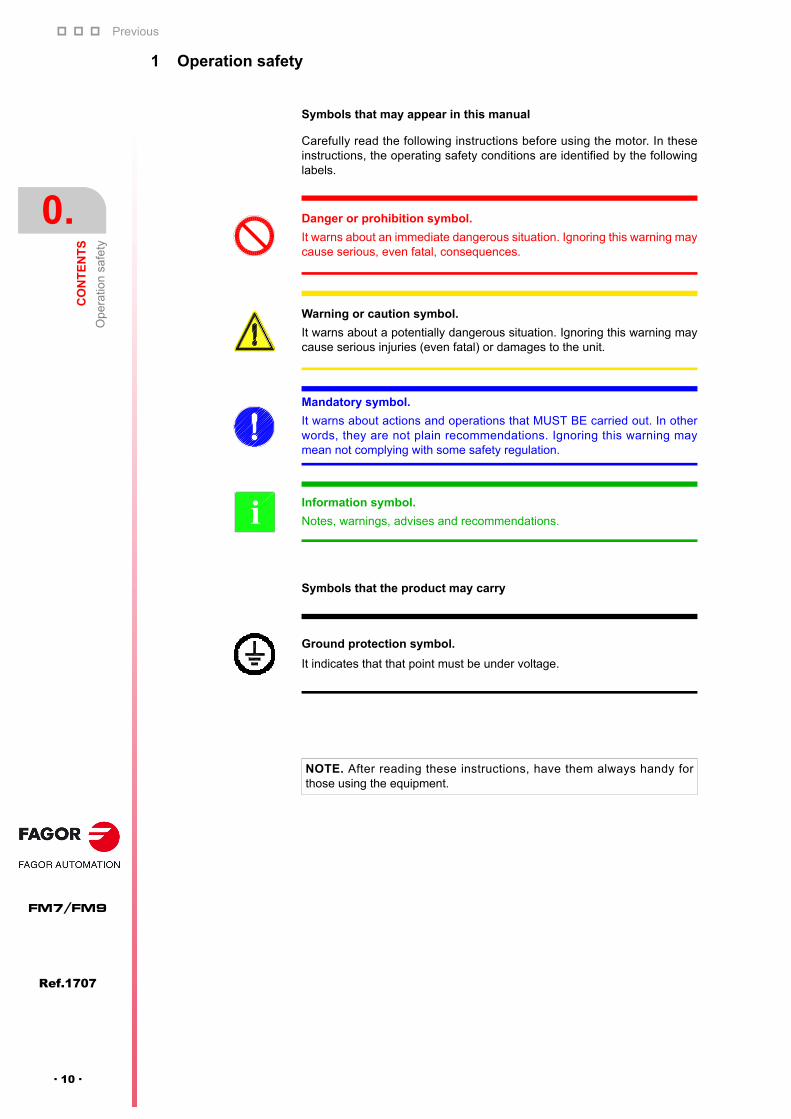
Symbols that may appear in this manual
Carefully read the following instructions before using the motor. In theseinstructions, the operating safety conditions are identified by the followinglabels.
Symbols that the product may carry
Danger or prohibition symbol.
It warns about an immediate dangerous situation. Ignoring this warning maycause serious, even fatal, consequences.
Warning or caution symbol.
It warns about a potentially dangerous situation. Ignoring this warning maycause serious injuries (even fatal) or damages to the unit.
Mandatory symbol.
It warns about actions and operations that MUST BE carried out. In otherwords, they are not plain recommendations. Ignoring this warning maymean not complying with some safety regulation.
Information symbol.
Notes, warnings, advises and recommendations.i
Ground protection symbol.
It indicates that that point must be under voltage.
NOTE. After reading these instructions, have them always handy forthose using the equipment.
Previous
CO
NT
EN
TS
Usa
ge
0.
Ref.1707
· 11 ·
FM7/FM9
2 Usage
DANGER.
Observe the following sections to avoid electrical discharges or any harm.
Take to ground the ground terminals of the motor and of the drive asspecified by your international and/or local electrical regulation. Ignoring thiswarning may cause electrical discharges.
Use a ground connection according to the standard local and/or internationalregulation.
Do not damage the cables or apply excessive force on them. Do not loadheavy items on them or crimp them with bolts or stapes. Ignoring thiswarning may cause electrical discharges.
WARNING.
Consider only the motor-drive combinations specified in the manual. Ignoringthis warning may cause poor performance or not to work at all.
Use the shortest cables possible in the electrical installations. Separate thepower cables from the signal cables. The noise on the signal cables maycause vibrations or poor performance of the unit.
Never install them in places exposed to water splashes, gasses andflammable or corrosive liquids or near flammable substances. Ignoring thiswarning may cause fire or poor performance.
Use it under the following ambient and work conditions:
Interiors without corrosive or explosive gasses.
Ventilated places without dust or metal particles.
Ambient temperature and relative humidity indicated in this manual.
Altitude 1000 meters above sea level.
Locations that may be cleaned, maintained and tested.

Previous
0.
CO
NT
EN
TS
Sto
rag
e
18
Ref.1707
FM7/FM9
· 12 ·
3 Storage
DANGER.
Do not store the unit in places exposed to water splashes or corrosive liquidsor gasses.
MANDATORY.
Store the motor horizontally and protected against any possible blow. Makesure that no strange elements get in through the openings of the coolingsystem.
Store the equipment avoiding direct exposure to the sun, keeping temperatureand humidity within the specified ranges (temperature between 0 °C (32 °F)and 60 °C (140 °F) and relative humidity between 5 % and 95 %).

Previous
CO
NT
EN
TS
Shi
ppin
g
0.
Ref.1707
· 13 ·
FM7/FM9
4 Shipping
WARNING.
Do not pull the cables or lift the motor up from its shaft in transit. Ignoring thiswarning may cause personal injury or poor motor performance due to damageto the motor.
Do not load the products too much. Ignoring this warning may cause the loadto break or personal injury.
MANDATORY.
Use only the eyebolts of the motor to lift it up and transport it. Do not try tomove it when it is connected to other equipment.
Before lifting it or moving it, make sure that they eyebolts are properly boltedin, the load is balanced and the cable and the sling used to move the motoris the right one.

Previous
0.
CO
NT
EN
TS
Inst
alla
tion
18
Ref.1707
FM7/FM9
· 14 ·
5 Installation
WARNING.
Do not climb on top of the motor nor load it with heavy objects. Ignoring thiswarning may cause personal injury.
Do not block either the air intake or the air output in ventilated motors andprevent strange materials from getting in. Ignoring this warning may causefire or damage to the unit.
When unpacking, use the proper tool to open the box. Ignoring this warningmay cause personal injury.
Cover the rotary parts so they cannot be touched. Ignoring this warning maycause personal injury.
The motor shaft extension is covered with anti-corrosive paint. Beforeinstalling the motor, remove the paint with a cloth dampened in liquiddetergent.
MANDATORY.
When connecting the motor to the machine load, special care must be takenwith centering, the tension of the pulley and the parallelism of the pulley.
A flexible coupling must be used to couple the motor with the machine load.
The encoder attached to the motor shaft is a precision element. Do not applyexcessive force on to the drive shaft. The machine must be designed so theaxial and radial loads applied to the shaft extension while in operation mustbe within the range indicated in this manual for this model.
No additional machining must be carried out to the motor.
Flange-mount models may be installed with the load placed horizontally orvertically at the drive shaft with the motor shaft extension facing down (onlyon FM7 series). On FM9 series, the shaft extension may be facing up ordown. If the motor shaft is horizontal, the terminal box must be facing up (onapplicable models). Foot-mount models must be installed on the floor withthe foot down or vertically with the shaft extension facing down (only on FM7models). On FM9 series, the shaft extension may be facing up or down.
For further details, refer to this manual for the possible builts for each model.
Previous
CO
NT
EN
TS
Cab
ling
0.
Ref.1707
· 15 ·
FM7/FM9
6 Cabling
MANDATORY.
The installation must comply with Directive EMC 2014/30/EU.
The motor is component to be incorporated on machines. They must complywith Machine Safety Directive 2006/42/EC and cannot be started up untilthis directive is met.
Install the cables safely according to the connection diagrams. Ignoring thiswarning may cause the motor to run away and personal injury.
Make sure that the power input is off before doing the installation.
Foresee a protection circuit so the main machine is not connected when themotor-fan group is not running (when applicable).
Carry out the right ground connection and electrical noise control(disturbances).
Use the shortest cables possible in the installation. Run the power cables asfar away from the signal cables as possible. Do not run the power cables andthe signal cables through same cable hose or conduit. The noise in signalcables may cause vibration or poor performance.
Use the cables specified by FAGOR. When using other cables, check therated current of the unit and bear in mind the work environment in order toproperly select the cables.

Previous
0.
CO
NT
EN
TS
Ope
ratio
n
18
Ref.1707
FM7/FM9
· 16 ·
7 Operation
WARNING.
Do not run the unit with the lid of the terminal box open. After cabling (whenapplicable), do not forget to close it. Ignoring this danger warning may causeelectrical discharges.
To properly check the motor, it must be properly secured and disconnectedfrom the machine load. Then, run the pertinent checks and connect themachine load again. Ignoring this warning may cause personal injury.
In case of error or alarm, correct its cause. First verify the safety conditionsand then resume the operation after eliminating the error. See the «safetyconditions» section of the “man_dds_hard.pdf” manual and chapter 14.«error codes and messages» of the drive manual “man_dds_ soft.pdf”.
If there is a momentary power loss, disconnect the power supply. Themachine may run suddenly causing personal injury.
MANDATORY.
Do not attempt to move the motor while it is attached to another unit withoutfreeing it first.
Use only the eyebolts of the motor to lift it up or move it.

Previous
CO
NT
EN
TS
Ma
inte
nan
ce a
nd in
spec
tion
0.
Ref.1707
· 17 ·
FM7/FM9
8 Maintenance and inspection
DANGER.
Only authorized personnel may take the unit apart and repair the unit.
Contact your FAGOR representative before taking the motor apart.
See the instruction of the following table to carry out the inspection and dailymaintenance of the motor. The AC spindle motor only needs a simple dailyinspection. The inspection periods indicated in the table are only a guideline.Adjust the inspection periods depending on the operating conditions andwork environment.
Inspection items
Frequency Operation Remarks
Vibration & noise
Daily Touch & listenVibration and noise mustnot exceed normal values.
OutsideAccording to requirements
Clean with a dry cloth orcompressed air
Insulation resistance
Annual Disconnect the motor from the drive and verify that the resistance is > 10 M measured with 500 V tes-ter
If the resistance is < 10 M, contact FAGOR. Do not measure the isolation resistance or test the limit voltage at the encoder
Overrall Every 12000 hours or 5 years (whichever co-mes first)
Contact your FAGOR agent
Do not try to solve failuresor do any cleaning by thirdparties
Note. Measure the isolation resistance between each phase U, V and W of the power cablesand the armature ground (FG).

0.
CO
NT
EN
TS
Previous
Ref.1707
FM7/FM9
· 18 ·
1
Ref.1707
· 19 ·
FM7/FM9
DESCRIPTION
1.1 Features and design
FAGOR FM7/FM9 series motors are asynchronous, also called inductionmotors, with a two-pole-pair (4 pole) squirrel cage rotor and are especiallydesigned to work on machine tool spindles.
These motor families group different series. Thus, the FM7 family has the(E01, E02 and E03) series depending on the maximum speed they can reach.There is also a fourth series (HS3) with a hollow shaft for cooling the tool fromthe spindle.
The FM9 family only has the E01 series.
Its features are:
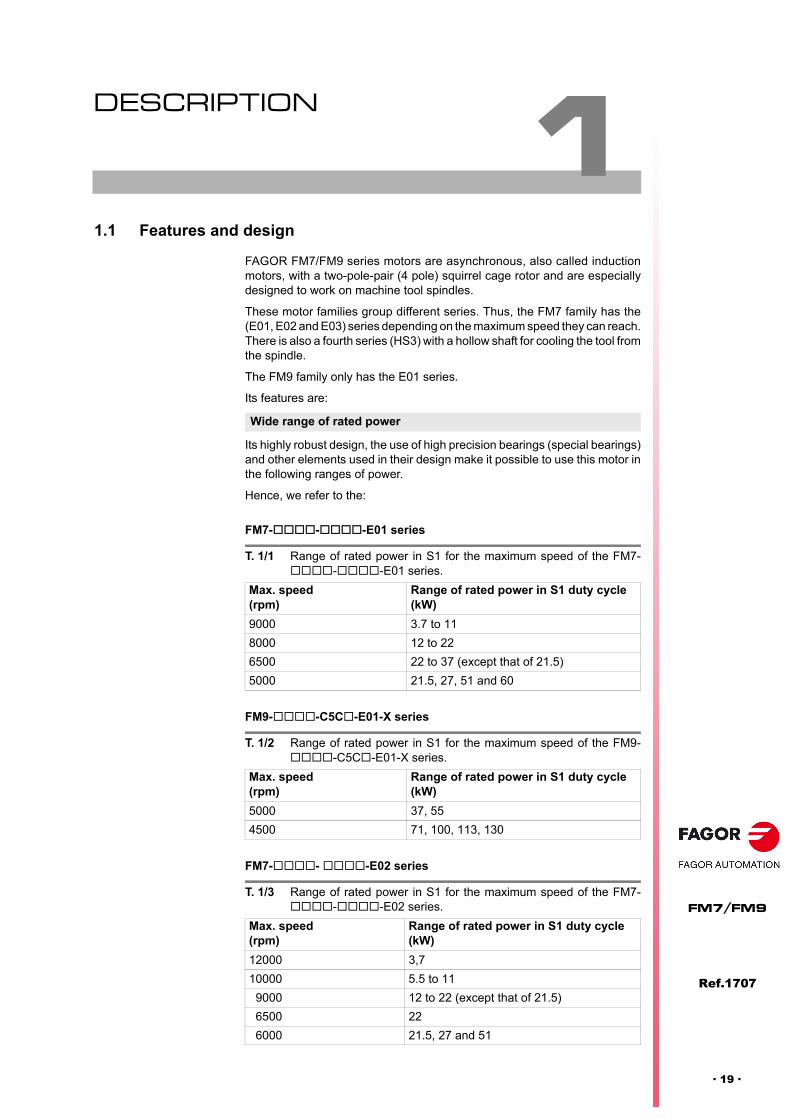
Its highly robust design, the use of high precision bearings (special bearings)and other elements used in their design make it possible to use this motor inthe following ranges of power.
Hence, we refer to the:
FM7---E01 series
FM9--C5C-E01-X series
FM7-- -E02 series
Wide range of rated power
T. 1/1 Range of rated power in S1 for the maximum speed of the FM7---E01 series.
Max. speed (rpm)
Range of rated power in S1 duty cycle (kW)
9000 3.7 to 11
8000 12 to 22
6500 22 to 37 (except that of 21.5)
5000 21.5, 27, 51 and 60
T. 1/2 Range of rated power in S1 for the maximum speed of the FM9--C5C-E01-X series.
Max. speed (rpm)
Range of rated power in S1 duty cycle (kW)
5000 37, 55
4500 71, 100, 113, 130
T. 1/3 Range of rated power in S1 for the maximum speed of the FM7---E02 series.
Max. speed (rpm)
Range of rated power in S1 duty cycle (kW)
12000 3,7
10000 5.5 to 11
9000 12 to 22 (except that of 21.5)
6500 22
6000 21.5, 27 and 51

Description
1.
DE
SC
RIP
TIO
N
Fea
ture
s an
d d
esig
n
30
Ref.1707
FM7/FM9
· 20 ·
FM7---E03 series
FM7---HS3 series
The mounting methods are:
A low level of vibration is achieved by reducing the size of the motor andadjusting the balancing for high speed.
For the FM7 family, the motor protection level meets the IP 44 standard andmay have a standard magnetic TTL encoder in all the series (except in theE600) or a C axis 1024 ppt SinCosTM StegmannTM sinusoidal encoder that isoptional in E01 series (except in the E600 that is optional) and E02 series thatare very reliable for velocity and position feedback. The E03/HS3 series donot have the "C axis encoder" feedback as an option.
For the FM9 family, the motor protection level meets IP 54 and offers a C axis1024 ppt SinCosTM StegmannTM sinusoidal encoder.
For the FM7 family, all series have a fan connected to three-phase 400 VAC (50/60Hz) as independent cooling system. The cooling air goes inthrough the machine load end and goes out through its opposite end, henceavoiding orienting the machine in the direction of the air output.
All models of the HS3 series have air cooling and are especially designed tobe mounted directly on the spindle. It has a hollow shaft that allows the coolingair flow to the tool that has internal cooling directly from the spindle itself.
For the FM9 family, all the models of the E01 series (except the B037) comewith a three-phase fanthat may be connected to 230/400 V AC (/Y) - 50 Hzor to 460 VAC (Y) - 60 Hz as an independent cooling system. The cooling airgoes in through the machine load end and goes out through its opposite end,hence avoiding orienting the machine in the direction of the air output.
T. 1/4 Range of rated power in S1 for the maximum speed of the FM7---E03 series.
Max. speed (rpm)
Range of rated power in S1 duty cycle (kW)
15000 5.5 to 7.5
12000 11 to 22
T. 1/5 Range of rated power in S1 for the maximum speed of the FM7---HS3 series.
Max. speed (rpm)
Range of rated power in S1 duty cycle (kW)
15000 7.5
12000 11 to 22
T. 1/6 Mounting methods.
Series Mounting type
FM7---E01 Foot, flange, foot+flange
FM9--C5C-E01-X Foot+flange
FM7---E02 Foot, flange, foot+flange
FM7---E03 Flange
FM7---HS3 Flange
Low vibration
High reliability
Cooling
Description
DE
SC
RIP
TIO
N
Fea
ture
s an
d d
esig
n
1.
Ref.1707
· 21 ·
FM7/FM9
For the la familia FM7, the E03/HS3 series have a winding with 6 differentterminals for star (Y) or delta (triangle) connection. It is also possible to togglefrom one to the other without stopping the motor using a maneuver with twoexternal magnetic contactors located between the motor and the drive makeit possible to select material removing conditions at low speed and high torque(star winding connection) or fine machining at high speed and low torque (deltawinding connection).
For the FM9 family, although the E01 series also has 6-terminal winding, onlyconsider the star (Y) connnection as the motors leave the factory.
Star delta winding connection

Description
1.
DE
SC
RIP
TIO
N
Ou
tsid
e ap
pea
ran
ce
30
Ref.1707
FM7/FM9
· 22 ·
1.2 Outside appearance
The following figure shows the external appearance of FAGOR FM7/FM9asynchronous spindle motors and the location of the terminal box that hasthe connectors for connecting power, the motor feedback and the fan.
F. 1/1
Asynchronous spindle motors. A. FM7 family. B. FM9 family.
(A)
(B)
Terminal box
Fan
Terminal box
Fan
Description
DE
SC
RIP
TIO
N
Ter
min
al b
ox. L
ayou
t and
iden
tific
atio
n
1.
Ref.1707
· 23 ·
FM7/FM9
1.3 Terminal box. Layout and identification
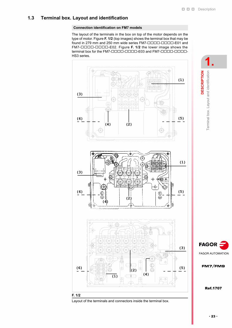
The layout of the terminals in the box on top of the motor depends on thetype of motor. Figure F. 1/2 (top images) shows the terminal box that may befound in 279 mm and 250 mm wide series FM7---E01 andFM7---E02. Figure F. 1/2 the lower image shows theterminal box for the FM7---E03 and FM7---HS3 series.
Connection identification on FM7 models
F. 1/2
Layout of the terminals and connectors inside the terminal box.
(1)
(2)
(3)
(4)(6) (5)
(5)(1)
(2)
(3)
(4)(6)
(1)
(3)
(6) (5)(2)(4)
Description
1.
DE
SC
RIP
TIO
N
Ter
min
al b
ox. L
ayou
t and
iden
tific
atio
n
30
Ref.1707
FM7/FM9
· 24 ·
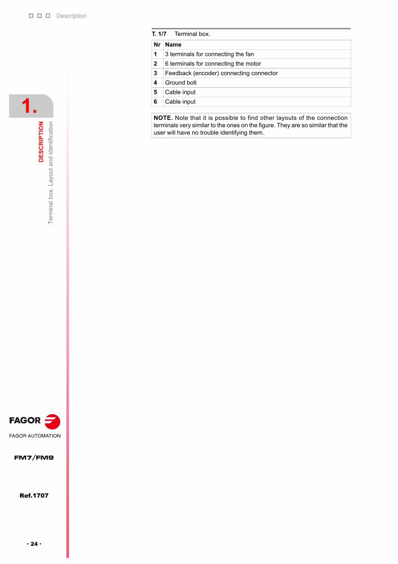
T. 1/7 Terminal box.
Nr Name
1 3 terminals for connecting the fan
2 6 terminals for connecting the motor
3 Feedback (encoder) connecting connector
4 Ground bolt
5 Cable input
6 Cable input
NOTE. Note that it is possible to find other layouts of the connectionterminals very similar to the ones on the figure. They are so similar that theuser will have no trouble identifying them.

Description
DE
SC
RIP
TIO
N
Ter
min
al b
ox. L
ayou
t and
iden
tific
atio
n
1.
Ref.1707
· 25 ·
FM7/FM9
The layout of the terminals in the box on top of the motor depends on thetype of motor. F. 1/3 the upper image shows the terminal box for the FM9-B037-C5C-E01 and FM9-B055-C5C-E01-A models. F. 1/3 the lowerimage shows the terminal box for the FM9-B071-C5C-E01, FM9-A100-C5C-E01, FM9-B113-C5C-E01 and FM9-A130-C5C-E01 models.
Connection identification on FM9 models
F. 1/3
Layout of the terminals and connectors inside the terminal box depending onmotor model.
T. 1/8 Terminal box.
Nr Name
1 Terminals/plates for motor power connection
2 Connector for encoder connection
3 Ground bolt
4 Cable gland(s) of the power cable hose
NOTE. Observe that the fan connecting terminals are in another smallerterminal box attached to the fan.
(2)(3)
(1)
(4)
(1)
(2)
(3)
(4)

Description
1.
DE
SC
RIP
TIO
N
Gen
era
l ch
arac
teris
tics
30
Ref.1707
FM7/FM9
· 26 ·
1.4 General characteristics
General technical data of FM7 models
T. 1/9 General technical data. FM7, E01/E02 series.
FM7---E01 / FM7---E02
Motor type Induction. Squirrel cage
Thermal protection(meets IEC 60034-6 standard)
NTC thermistor
Level of vibration(meets IEC 60034-14 standard)
V5 - V10 (standard)V3 - V5 (optional)
Type of construction(meets IEC 60034-7 standard)
Horizontal: IM B3, IM B5, IM B35Vertical: IM V1, IM V5, IM V15
Electrical insulation of the winding(meets IEC 60034 standard)
Class F (155 °C / 311 °F)
Degree of protection(meets IEC 60034-5 standard)
IP 44
Storage temperature From 0 °C to 60 °C (-32 °F to 140 °F)
Ambient temperature allowed From 0 °C to 40 °C (-32 °F to 104 °F)
Working ambient humidity 95 % max. (non condensing)
Maximum recommended altitude 1000 m (3281 ft) above sea level
Fan voltage400 V AC (three phase) - 50/60 HzIndependent voltage supply
Withstanding of the isolation voltage 1800 V AC in one minute
Insulation resistance 500 V AC, 10 M
FeedbackMagnetic TTL encoder. Standard.C axis sinusoidal 1024 ppt SinCosTM StegmannTM
encoder. Optional.
Conformity standard IEC 34-1
T. 1/10 General technical data. FM7, E03/HS3 series.
FM7---E03 / FM7---HS3
Motor type Induction. Squirrel cage
Thermal protection(meets IEC 60034-6 standard)
NTC thermistor
Level of vibration(meets IEC 60034-14 standard)
V3 (standard)
Type of construction(meets IEC 60034-7 standard)
Horizontal: IM B5Vertical: IM V1
Electrical insulation of the winding(meets IEC 60034 standard)
Class F (155 °C / 311 °F)
Degree of protection(meets IEC 60034-5 standard)
IP 44
Storage temperature From 0 °C to 60 °C (-32 °F to 140 °F)
Ambient temperature allowed From 0 °C to 40 °C (-32 °F to 104 °F)
Working ambient humidity 95 % max. (non condensing)
Maximum recommended altitude 1000 m (3281 ft) above sea level
Fan voltage400 V AC (three phase) - 50/60 HzIndependent voltage supply
Withstanding of the isolation voltage 1800 V AC in one minute
Insulation resistance 500 V AC, 10 M
Feedback Magnetic TTL encoder (standard)
Conformity standard IEC 34-1

Description
DE
SC
RIP
TIO
N
Gen
era
l ch
arac
teris
tics
1.
Ref.1707
· 27 ·
FM7/FM9
Notes
The “F” classification of the winding isolation is based on its maximum running temperature capability.
This temperature is 155 °C (311 °F) and represents the maximum operating temperature for the winding.At this temperature, if the motor were running in a clean and dry environment for up to 40 hours a week,it would have a life expectancy of 10 to 20 years before the isolation would get damaged due to heat andwould no longer withstand the applied voltage.
General technical data of FM9 models
T. 1/11 General technical data. FM9, E01 series.
FM9--C5C-E01-
Motor type Induction. Squirrel cage
Thermal protection(meets IEC 60034-6 standard)
KTY84-130 thermistor
Level of vibration(meets IEC 60034-14 standard)
V5 (standard)
Type of construction(meets IEC 60034-7 standard)
Horizontal: IM B3, IM B5, IM B35Vertical: IM V1, IM V5, IM V15 IM V3, IM V6, IM V36
Electrical insulation of the winding(meets IEC 60034 standard)
Class F (155 °C / 311 °F)
Degree of protection(meets IEC 60034-5 standard)
IP 54
Storage temperature From -10 °C to +60 °C (14 °F to 140 °F)
Ambient temperature allowed From -15 °C to +40 °C (5 °F to 104 °F)
Working ambient humidity 80 % max. (non condensing)
Maximum recommended altitude 1000 m (3281 ft) above sea level
Fan voltage230/400 V AC (/Y) (three-phase) - 50 Hz460 V AC (Y) (three phase) - 60 HzIndependent voltage supply
Withstanding of the isolation voltage 1200 V AC
Insulation resistance 30 M
FeedbackC axis 1024 ppt sinusoidal SinCosTM StegmannTM
encoder. Standard.
Conformity standard IEC 34-1
Description
1.
DE
SC
RIP
TIO
N
Tem
pera
ture
se
nsor
s
30
Ref.1707
FM7/FM9
· 28 ·
1.5 Temperature sensors
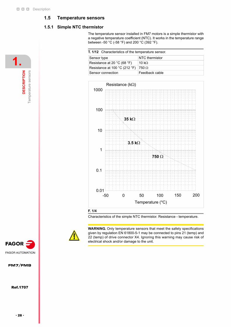
1.5.1 Simple NTC thermistor
The temperature sensor installed in FM7 motors is a simple thermistor witha negative temperature coefficient (NTC). It works in the temperature rangebetween -50 °C (-58 °F) and 200 °C (392 °F).
T. 1/12 Characteristics of the temperature sensor.
Sensor type NTC thermistor
Resistance at 20 °C (68 °F) 10 kResistance at 100 °C (212 °F) 750 Sensor connection Feedback cable
F. 1/4
Characteristics of the simple NTC thermistor. Resistance - temperature.
Temperature (°C)
-50 0 50 100 150 200
3.5 k
750
0.01
0.1
1
10
100
1000Resistance (k )
35 k
WARNING. Only temperature sensors that meet the safety specificationsgiven by regulation EN 61800-5-1 may be connected to pins 21 (temp) and22 (temp) of drive connector X4. Ignoring this warning may cause risk ofelectrical shock and/or damage to the unit.

Description
DE
SC
RIP
TIO
N
Tem
pera
ture
se
nsor
s
1.
Ref.1707
· 29 ·
FM7/FM9
1.5.2 KTY84-130 thermistor
The temperature sensor in FM9 is a KTY84-130 thermistor used as thermalprotection of the motor and it is located in the stator winding. It has a positivetemperature coefficient (PTC) and they should be used in control andmeasurement systems within a range between -40 °C (-40 °F) and +300 °C(+572 °F).
The following figure shows the graph of the resistance variation of thesensor as a function of the ambient temperature (average values):
T. 1/13 Characteristics of the temperature sensor.
Sensor type KTY84-130
Approx. resistance at 20 °C (68 °F) 581 Approx. resistance at 100 °C (212 °F) 1000 Sensor connection Feedback cable
Motor series In all FM9 models
F. 1/5
KTY84-130 sensor resistance depending on room (ambient) temperature.
NOTE. The two wires of the temperature sensor are included in thefeedback cable and it will be connected to the corresponding connector ofthe drive.
3 0 02 0 01 0 00- 1 0 00
1
2
R ( k )
T a m b ( ° C )
I c o n t = 2 m A
WARNING. The temperature sensor KTY84-130 has polarity. If you wish tomanufacture your own feedback cable, make sure that the polarity is correctwhen soldering these two wires to the corresponding pins of the connector.See the motor feedback connector diagrams later on.
Only temperature sensors that meet the safety specifications given byregulation EN 61800-5-1 may be connected to pins 21 (temp) and 22 (temp)of drive connector X4. Ignoring this warning may cause risk of electricalshock and/or damage to the unit.

Description
1.
DE
SC
RIP
TIO
N
Fee
dba
ck d
evi
ces
30
Ref.1707
FM7/FM9
· 30 ·
1.6 Feedback devices
1.6.1 Magnetic TTL encoder
Standard feedback device in all FM7 spindle motors. It consists of a magneticdisk used as a position detector. There are three feedback signals. Two signalsfor the A and B phases of 1024 pulses per turn and one pulse per turn (C signal)to indicate the starting position.
The following diagram shows the relationship between the encoderconfiguration and the output phase when turning the shaft clockwise (CW).
The convention of the motor shaft turning direction is established accordingto:
1.6.2 C axis SinCos encoder
It is the optional feedback device of the E01 (except for the FM7-E600 whichis the standard feedback device) and E02 series of FM7 spindle motors. It isalso the standard feedback device in the E01 series of FM9 spindle motors.It consists of a non-magnetic disk used as a position detector. There are fourfeedback signals. Two reference signals RefSin and RefCos and two Sinand Cos signals of 1024 pulses per turn whose composition determines theabsolute position of the axis per turn.
The following diagram shows the relationship between the configuration ofthe C axis SinCos encoder and the output phase when turning the shaftclockwise (CW):
The convention of the motor shaft turning direction is established accordingto:
F. 1/6
Magnetic TTL encoder configuration. Output phases.
Feedback direction
Shaft turning convention
CW (+ turning direction)
CCW (- turning direction)
Axis rotation (CW)
90°
A phase(PCA)
B phase(PCB)
C phase (PCC)
NSN S
SN
SNS
N
A
B
C
Magnetic drum
Shaft
Magnetic sensor(magnetic resistance element)
CCW
CW
F. 1/7
C axis SinCosTM encoder configuration. Output phases.
Feedback direction
Shaft turning convention
CW (+ turning direction)
CCW (- turning direction)
2.5 V
SIN
CO
S
REFSINREFCOS
Axis rotation (CW)
1 V
CCW
CW
2
Ref.1707
· 31 ·
FM7/FM9
ELECTRICAL CHARACTERISTICS
2.1 Definitions
Maximum turning speed allowed. nmax
The maximum speed allowed nmax is determined by mechanical design(bearing designed in terms of fatigue, short-circuit ring of the squirrel-cagerotor) and electrical design (restricting voltage characteristics).
Maximum permanent turning speed. n1
It is the maximum speed allowed in permanent mode without any speed dutycycle.
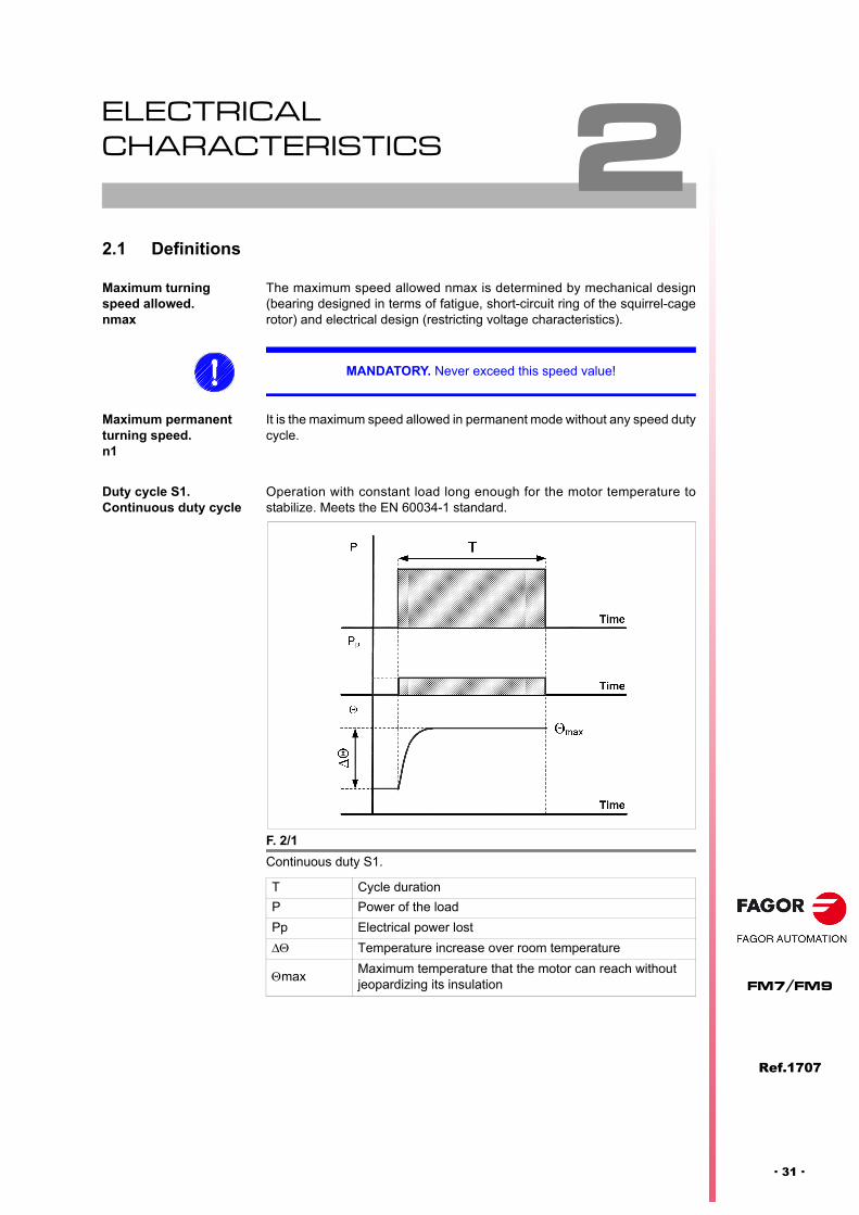
Duty cycle S1. Continuous duty cycle
Operation with constant load long enough for the motor temperature tostabilize. Meets the EN 60034-1 standard.
MANDATORY. Never exceed this speed value!
F. 2/1
Continuous duty S1.
T Cycle duration
P Power of the load
Pp Electrical power lost
Temperature increase over room temperature
maxMaximum temperature that the motor can reach without jeopardizing its insulation

Electrical characteristics
2.
EL
EC
TR
ICA
L C
HA
RA
CT
ER
IST
ICS
Def
initi
ons
74
Ref.1707
FM7/FM9
· 32 ·
S6 duty. Intermittent duty cycle
Uninterrupted periodic service with intermittent load, also called continuousservice with intermittent load. It consists of a succession of identical cyclesthat have a constant-load period and another one without load, there are norest intervals nor stop intervals. If no other value is indicated, the load dutycycle will be referred to a time of 10 minutes. Meets the EN 60034-1standard. Hence:
Motor limits On induction motors, the speed and power values are limited by thermal andmechanical reasons. The maximum current is only limited by the thermalcharacteristics of the motor windings.
Heat losses are stored in the motor and dissipated by cooling systems. Themotor temperature depends on, among other things, the load duty.
The characteristics for continuous duty S1 and intermittent duty S6-40%define the outputs allowed for a room temperature of up to 40 °C (104 °F). Forthis case, the temperature increase of the winding is 100 °C (212 °F).
S6 -40% tc = 4 minutes with load
tc = 6 minutes without load
F. 2/2
Periodic uninterrupted duty cycle with intermittent load S6.
T Cycle duration
tc Load time
tv Time without load
tc / TRunning factor (e.g. 4 min / 10 min = 0.4) running f.: 40%
P Power of the load
Pp Electrical power lost
Temperature increase over room temperature
maxMaximum temperature that the motor can reach without jeopardizing its insulation.
Thermal limitation
MANDATORY. Never exceed the critical temperature of the motor!
Mechanical limitation
MANDATORY. Never exceed the mechanical speed limit (nmax) because itcould damage the bearings!
Electrical characteristics
EL
EC
TR
ICA
L C
HA
RA
CT
ER
IST
ICS
Op
erat
ing
mod
es
2.
Ref.1707
· 33 ·
FM7/FM9
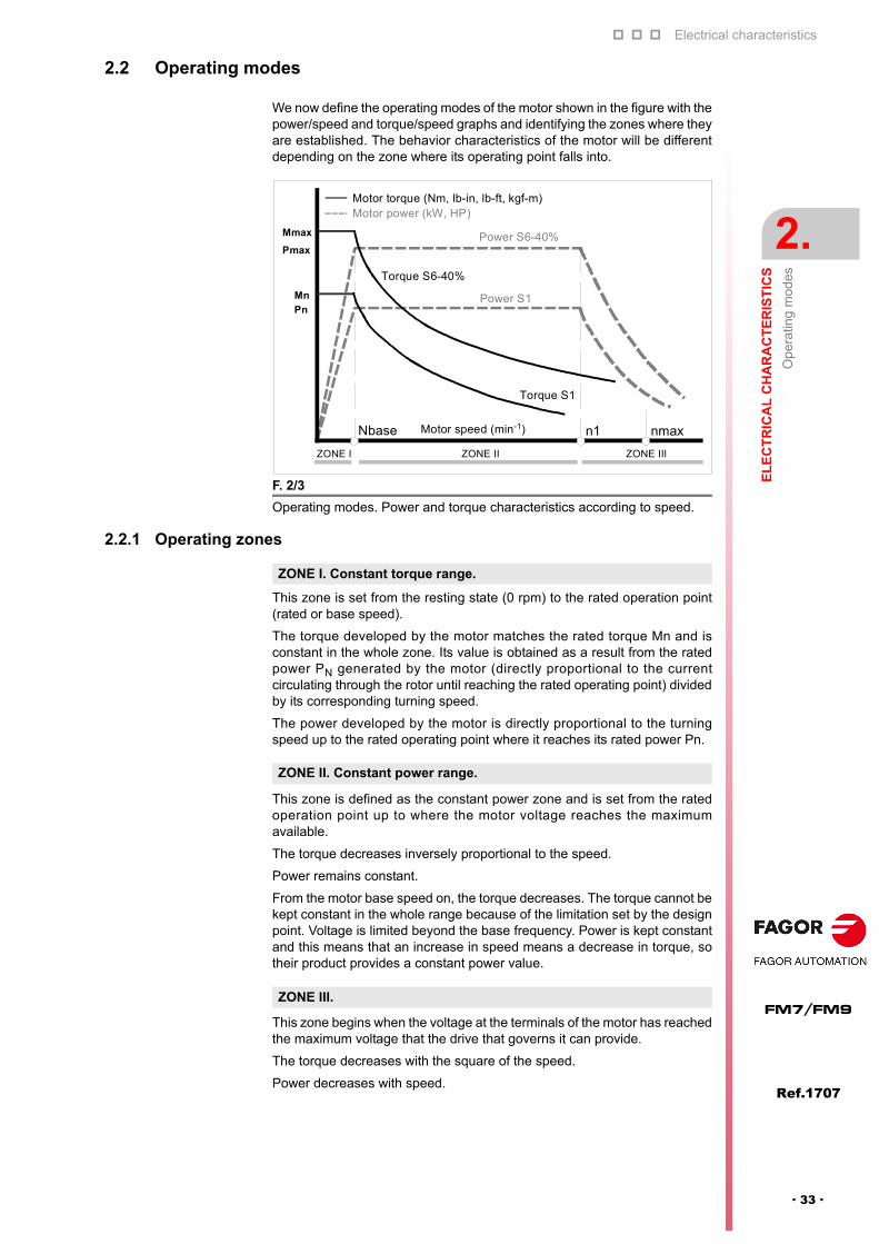
2.2 Operating modes
We now define the operating modes of the motor shown in the figure with thepower/speed and torque/speed graphs and identifying the zones where theyare established. The behavior characteristics of the motor will be differentdepending on the zone where its operating point falls into.
2.2.1 Operating zones
This zone is set from the resting state (0 rpm) to the rated operation point(rated or base speed).
The torque developed by the motor matches the rated torque Mn and isconstant in the whole zone. Its value is obtained as a result from the ratedpower PN generated by the motor (directly proportional to the currentcirculating through the rotor until reaching the rated operating point) dividedby its corresponding turning speed.
The power developed by the motor is directly proportional to the turningspeed up to the rated operating point where it reaches its rated power Pn.
This zone is defined as the constant power zone and is set from the ratedoperation point up to where the motor voltage reaches the maximumavailable.
The torque decreases inversely proportional to the speed.
Power remains constant.
From the motor base speed on, the torque decreases. The torque cannot bekept constant in the whole range because of the limitation set by the designpoint. Voltage is limited beyond the base frequency. Power is kept constantand this means that an increase in speed means a decrease in torque, sotheir product provides a constant power value.
This zone begins when the voltage at the terminals of the motor has reachedthe maximum voltage that the drive that governs it can provide.
The torque decreases with the square of the speed.
Power decreases with speed.
F. 2/3
Operating modes. Power and torque characteristics according to speed.
Motor speed (min-1) n1
Motor power (kW, HP)
ZONE I
Nbase
Motor torque (Nm, lb-in, lb-ft, kgf-m)
nmax
Power S6-40%
Torque S6-40%
Power S1
Torque S1
ZONE II ZONE III
Mmax
Pmax
Mn
Pn
ZONE I. Constant torque range.
ZONE II. Constant power range.
ZONE III.
Electrical characteristics
2.
EL
EC
TR
ICA
L C
HA
RA
CT
ER
IST
ICS
Influ
enc
e of
sup
ply
volta
ge
74
Ref.1707
FM7/FM9
· 34 ·
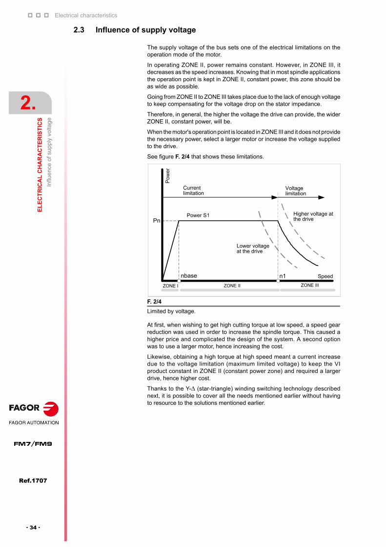
2.3 Influence of supply voltage
The supply voltage of the bus sets one of the electrical limitations on theoperation mode of the motor.
In operating ZONE II, power remains constant. However, in ZONE III, itdecreases as the speed increases. Knowing that in most spindle applicationsthe operation point is kept in ZONE II, constant power, this zone should beas wide as possible.
Going from ZONE II to ZONE III takes place due to the lack of enough voltageto keep compensating for the voltage drop on the stator impedance.
Therefore, in general, the higher the voltage the drive can provide, the widerZONE II, constant power, will be.
When the motor's operation point is located in ZONE III and it does not providethe necessary power, select a larger motor or increase the voltage suppliedto the drive.
See figure F. 2/4 that shows these limitations.
At first, when wishing to get high cutting torque at low speed, a speed gearreduction was used in order to increase the spindle torque. This caused ahigher price and complicated the design of the system. A second optionwas to use a larger motor, hence increasing the cost.
Likewise, obtaining a high torque at high speed meant a current increasedue to the voltage limitation (maximum limited voltage) to keep the VIproduct constant in ZONE II (constant power zone) and required a largerdrive, hence higher cost.
Thanks to the Y- (star-triangle) winding switching technology describednext, it is possible to cover all the needs mentioned earlier without havingto resource to the solutions mentioned earlier.
F. 2/4
Limited by voltage.
Power S1
n1
PnHigher voltage at the drive
Lower voltage at the drive
Current limitation
Pow
er
nbase Speed
ZONE I ZONE II ZONE III
Voltage limitation

Electrical characteristics
EL
EC
TR
ICA
L C
HA
RA
CT
ER
IST
ICS
Y-D
win
ding
con
nec
tion
switc
hin
g
2.
Ref.1707
· 35 ·
FM7/FM9
2.4 Y- winding connection switching
2.4.1 Y winding and winding
This connection is commonly used for AC induction motors. The motortorque and base speed depend on the motor impedance Z.
NOTE. Only the E03/HS3 series of asynchronous spindle motors of theFM7 family have a 6-lead winding that allows star-delta switching of theconnection.
F. 2/5
6-lead winding.
F. 2/6
Possible winding connections. A. Star (Y). B.Triangle ().
Y (star) connection
F. 2/7
Y (star) connection. Impedance Z.
U V W
X Y Z
Built6-Lead winding motor where U, V and, W are at oneend of the winding and X, Y, Z at the other end.
UsageA 6-lead winding may be connected according to aconfiguration:
In star
In triangle
See figure F. 2/6.
X-Y-Z
U
V W
ZU
WX
V Y(A) (B)
Z
Z
Z

Electrical characteristics
2.
EL
EC
TR
ICA
L C
HA
RA
CT
ER
IST
ICS
Y-D
win
ding
con
nec
tion
switc
hin
g
74
Ref.1707
FM7/FM9
· 36 ·
The voltage/frequency ratio (V/f) of this connection is based on the motoroperation point. At the high frequency, a power drop occurs due to motorimpedance.
When using this connection, the impedance Z of the motor is much lower thanin the previous case. The impedance equivalent to Z in a Y connection is Z/3.
A lower motor impedance means higher base frequency (base speed) andhigher maximum frequency, but remember that the maximum voltage islimited beyond the base speed.
F. 2/8
Voltage/frequency and power/frequency diagrams.
(triangle) connection
F. 2/9
(triangle) connection. Equivalent impedance in a Y connection.
F. 2/10
Comparison diagrams of voltage/frequency and power/frequency for deltaconnection.
0
Voltage
design point
frequency
0
Power
power surgedue to the impedanceof the motor
peak
rated
frequency
freq. basefreq. base
Vmax
00
Z/3
Z/3 Z/3
Z Z
Z
Equivalent to
� - winding Y - winding
Z/3
Z/3 Z/3
Z Z
Z
Equivalent to
-winding Y-winding
0
Power
peak
rated
frequency0
less torque
0
Voltage
frequency0
Vmax
base freq. Y base freq. max freq.
Vi
base freq. max freq.
highermax. speed

Electrical characteristics
EL
EC
TR
ICA
L C
HA
RA
CT
ER
IST
ICS
Y-D
win
ding
con
nec
tion
switc
hin
g
2.
Ref.1707
· 37 ·
FM7/FM9
2.4.2 Comparison charts F/f and M/f depending on Y- connection
It is therefore, interesting to be able to combine the advantages of bothwindings, i.e, to use Y-winding at low speed to provide high torque and deltawinding at high speed.
The Y- winding change will be carried out through two external magneticcontactors placed between the drive and the motor. If the user has asoftware version 06.18 or higher, this switch can be made without stoppingthe motor (at non-zero speed), in other cases, it will have to be donestopping the motor (zero speed).
For further details on the connection diagram of the “motor-contactors- drive”system in the electrical cabinet, see the relevant section in the installationchapter of this manual.
F. 2/11
Comparison charts P/f and M/f depending on Y or connection.
NOTE. The winding change provides high torque and wide constant powerrange with relatively small size drive.
F. 2/12
Power/speed graphs applying the winding connection change.
Power
frequency
base freq. max. freq.
Power
frequency
base freq. Y max. freq. Y
0
Torque
frequency0
base freq. Y max. freq. Y
frequency
base freq. max. freq.
Torque
00
00
00
Y (star) connection (triangle) connection
0
Power
0base speed -
Y
basespeed -
max.speed -
A B
Wide constant power range: A:Band high torque at low speed
star delta
Motor speed

Electrical characteristics
2.
EL
EC
TR
ICA
L C
HA
RA
CT
ER
IST
ICS
Tec
hnic
al d
ata.
Po
we
r/to
rque
-spe
ed g
rap
hs
74
Ref.1707
FM7/FM9
· 38 ·
2.5 Technical data. Power/torque-speed graphs
This section describes the power and torque graphs for the S1 and S6 40%duty cycles (cycle times of 10 minutes).
The tables that come with the graphs give the most important technical datathat characterize each model of this family of motors.
This section also classifies the FM7 and FM9 spindle motors by series.Therefore, the user must check his motor with the series it belongs to inorder to find the specific power/torque-speed graph for that motor.
Remember that there are five series:
FM7---E01
FM9--C5C-E01-
FM7---E02
FM7--S1D0-E03
FM7--S1D0-HS3
All the models belonging to the 5 series have 2 pairs of poles (4 poles).
Important notes
Note that, with FM9 motors larger than the B055:
the «FM9 motor + associated drive» combination is designed to work induty cycle S1.
a torque overload at high speed is allowed depending on the maximumcurrent allowed for the combination (power supply+drive). To estimate itsvalue, use the smallest rated power of the drive and that of the powersupplied minus 7 %.
Also keep in mind that, with FM9 motors larger than the B037, the DC BUSmust be configured at 675 V DC (for RPS power supplies) in order to obtainthe graph of rated power at high speed.
Explanatory notes Motors whose maximum speed equal to or higher than 8000 rpm should
have a keyless shaft and should be balanced under these conditions.
Chapter 6. SELECTION describes how to select the modular or compactdrive that will be governing the motor. Selection. Hence, the motor - driveassociation for all the models has been already defined.
All AC motors of the FM7/FM9 families governed by main spindle drivesmust be continuously ventilated while running, regardless of the dutycycle demanded by the application.
The windings of the FM7 of the FM7---E01/E02 serieshave a permanent Delta (triangle) connection.
The windings of the FM7 motors of the FM7-D-S1D0-E03/HS3series may be configured either in triangle or in star using two externalcontactors installed between the motor and the drive.
FM9 motor windings have a Y connection.
NOTE. Remember that when mentioning an S6 cycle in this manual, italways refers to this cycle with a 40% running factor.
NOTE. The maximum power and speed ranges covered by each serieswere already shown in chapter 1. DESCRIPTION.
NOTE. The windings of the FM7 motors “E01/E02 series” cannot havea Y (star) connection. They are internally connected in triangle andcannot be changed.

Electrical characteristics
EL
EC
TR
ICA
L C
HA
RA
CT
ER
IST
ICS
Tec
hnic
al d
ata.
Po
we
r/to
rque
-spe
ed g
rap
hs
2.
Ref.1707
· 39 ·
FM7/FM9
Symbols used
The following symbols appearing in the technical data tables mean:
The mass of the motor shown in the technical data tables appears for somemodels with the letters B/P/B+P. The values provided correspond to theapproximate mass of the motor depending on whether it is flange mount (B)or foot mount (P) or flange+foot mount (B+P). Hence, for example, whenonly showing B, it corresponds to the approximate mass of the motor thatcan only be flange mounted.
Y (star) connection
Delta (triangle) connection
Electrical characteristics
2.
EL
EC
TR
ICA
L C
HA
RA
CT
ER
IST
ICS
Tec
hnic
al d
ata.
Po
we
r/to
rque
-spe
ed g
rap
hs
74
Ref.1707
FM7/FM9
· 40 ·
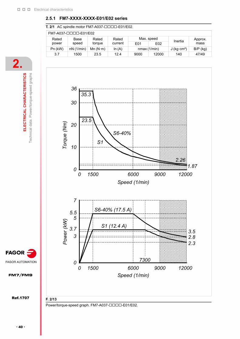
2.5.1 FM7-XXXX-XXXX-E01/E02 series
T. 2/1 AC spindle motor FM7-A037--E01/E02.
FM7-A037--E01/E02
Rated power
Basespeed
Ratedtorque
Ratedcurrent
Max. speedInertia Approx.
massE01 E02
Pn (kW) nN (1/min) Mn (N·m) In (A) nmax (1/min) J (kg·cm²) B/P (kg)
3.7 1500 23.5 12.4 9000 12000 140 47/49
F. 2/13
Power/torque-speed graph. FM7-A037--E01/E02.
Tor
que
(N
m)
35.336
0
23.5
S1
S6-40%
10
20
30
0 1500 6000 9000 12000
Speed (1/min)
Pow
er (
kW)
Speed (1/min)
0 1500 6000 9000 12000
2.32.83.5
7300
S6-40% (17.5 A)
S1 (12.4 A)
0
3
3.7
55.5
7
1.872.26
Electrical characteristics
EL
EC
TR
ICA
L C
HA
RA
CT
ER
IST
ICS
Tec
hnic
al d
ata.
Po
we
r/to
rque
-spe
ed g
rap
hs
2.
Ref.1707
· 41 ·
FM7/FM9
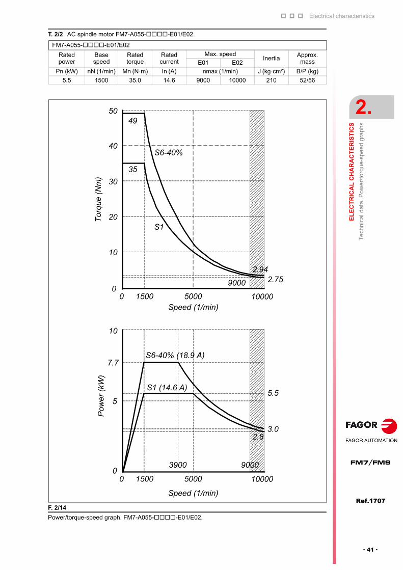
T. 2/2 AC spindle motor FM7-A055--E01/E02.
FM7-A055--E01/E02
Rated power
Basespeed
Ratedtorque
Ratedcurrent
Max. speedInertia Approx.
massE01 E02
Pn (kW) nN (1/min) Mn (N·m) In (A) nmax (1/min) J (kg·cm²) B/P (kg)
5.5 1500 35.0 14.6 9000 10000 210 52/56
F. 2/14
Power/torque-speed graph. FM7-A055--E01/E02.
Speed (1/min)
Tor
que
(N
m)
Pow
er (
kW)
Speed (1/min)
S6-40% (18.9 A)
S1 (14.6 A)5.5
3.02.8
5000 10000150000
5
7.7
10
3900 9000
5000 1000015000
49
0
10
20
30
40
50
S6-40%
S1
9000
35
2.752.94

Electrical characteristics
2.
EL
EC
TR
ICA
L C
HA
RA
CT
ER
IST
ICS
Tec
hnic
al d
ata.
Po
we
r/to
rque
-spe
ed g
rap
hs
74
Ref.1707
FM7/FM9
· 42 ·
T. 2/3 AC spindle motor FM7-A075--E01/E02.
FM7-A075--E01/E02
Rated power
Basespeed
Ratedtorque
Ratedcurrent
Max. speedInertia Approx.
massE01 E02
Pn (kW) nN (1/min) Mn (N·m) In (A) nmax (1/min) J (kg·cm²) B/P (kg)
7.5 1500 47.7 19.8 9000 10000 260 59/64
F. 2/15
Power/torque-speed graph. FM7-A075--E01/E02.
Tor
que
(Nm
)P
owe
r (k
W)
Speed (1/min)
0 1500 6000
9000
1000045000
4.55.0
S6-40% (27.0 A)
S1 (19.8 A)7.5
10
11
Speed (1/min)
0 1500 100005000
90000
15
30
45
60
75
71.5
47.7
S6-40%
S1
4.414.90

Electrical characteristics
EL
EC
TR
ICA
L C
HA
RA
CT
ER
IST
ICS
Tec
hnic
al d
ata.
Po
we
r/to
rque
-spe
ed g
rap
hs
2.
Ref.1707
· 43 ·
FM7/FM9
T. 2/4 AC spindle motor FM7-A090--E01/E02.
FM7-A090--E01/E02
Rated power
Basespeed
Ratedtorque
Ratedcurrent
Max. speedInertia Approx.
massE01 E02
Pn (kW) nN (1/min) Mn (N·m) In (A) nmax (1/min) J (kg·cm²) B/P (kg)
9.0 1500 57.4 25.1 9000 10000 330 68/73
F. 2/16
Power/torque-speed graph. FM7-A090--E01/E02.
Speed (1/min)
0 1500 5000
9000
10000
S6-40% (33.6 A)
S1 (25.1 A)
Pow
er (
kW)
15
13
10
9
6.8
5.9
5
Speed (1/min)
0 1500 6500 10000
900052500
Tor
que
(Nm
)
0
15
30
45
60
57.4
7582.4
90
S6-40%
S1
5.86.7
Electrical characteristics
2.
EL
EC
TR
ICA
L C
HA
RA
CT
ER
IST
ICS
Tec
hnic
al d
ata.
Po
we
r/to
rque
-spe
ed g
rap
hs
74
Ref.1707
FM7/FM9
· 44 ·
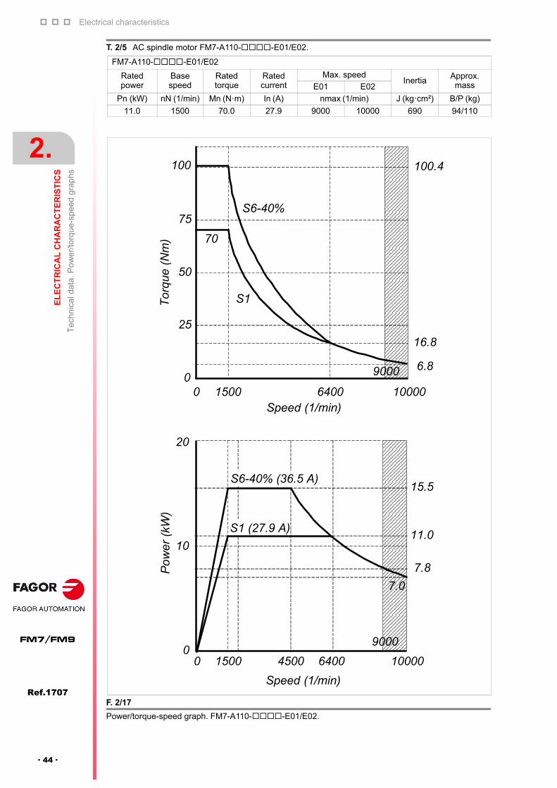
T. 2/5 AC spindle motor FM7-A110--E01/E02.
FM7-A110--E01/E02
Rated power
Basespeed
Ratedtorque
Ratedcurrent
Max. speedInertia Approx.
massE01 E02
Pn (kW) nN (1/min) Mn (N·m) In (A) nmax (1/min) J (kg·cm²) B/P (kg)
11.0 1500 70.0 27.9 9000 10000 690 94/110
F. 2/17
Power/torque-speed graph. FM7-A110--E01/E02.
0 1500 6400
9000
10000Speed (1/min)
Tor
que
(N
m)
S6-40%
S1
70
100.4
0
25
50
75
100P
ow
er (
kW)
S6-40% (36.5 A)
S1 (27.9 A)
15.5
7.8
0
10
20
11.0
7.0
6.8
16.8
Speed (1/min)
0 1500 6400 10000
9000
4500

Electrical characteristics
EL
EC
TR
ICA
L C
HA
RA
CT
ER
IST
ICS
Tec
hnic
al d
ata.
Po
we
r/to
rque
-spe
ed g
rap
hs
2.
Ref.1707
· 45 ·
FM7/FM9
T. 2/6 AC spindle motor FM7-A150--E01/E02.
FM7-A150--E01/E02
Rated power
Basespeed
Ratedtorque
Ratedcurrent
Max. speedInertia Approx.
massE01 E02
Pn (kW) nN (1/min) Mn (N·m) In (A) nmax (1/min) J (kg·cm²) B/P (kg)
15.0 1500 95.5 39.3 8000 9000 690 94/110
F. 2/18
Power/torque-speed graph. FM7-A150--E01/E02.
S6-40%
S1
143.9150
125
100
Tor
que
(N
m)
75
50
25
Speed (1/min)
0 1500 6800 90004600
80000
95.5
21.6
12.2
S6-40% (52.9 A)
S1 (39.3 A)
Pow
er
(kW
)
Speed (1/min)
0 1500 6800 90004600
8000
11.2
0
5
10
15
20
22
25
Electrical characteristics
2.
EL
EC
TR
ICA
L C
HA
RA
CT
ER
IST
ICS
Tec
hnic
al d
ata.
Po
we
r/to
rque
-spe
ed g
rap
hs
74
Ref.1707
FM7/FM9
· 46 ·
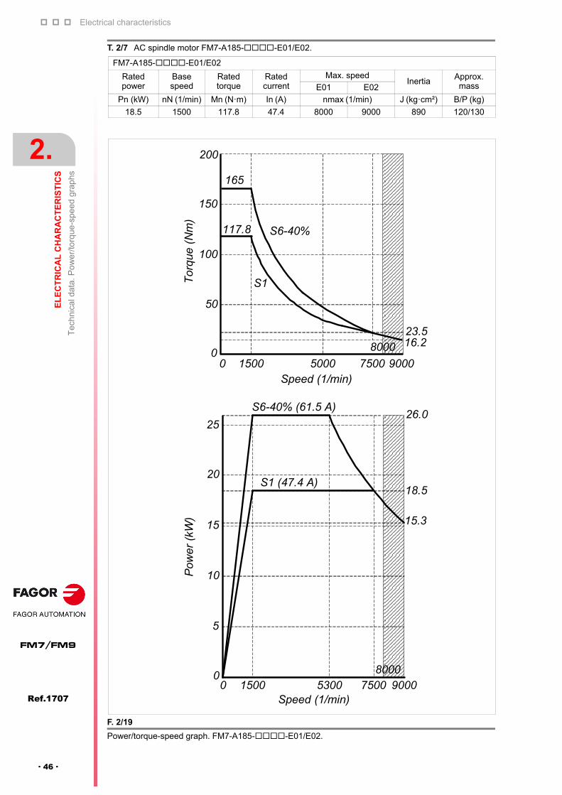
T. 2/7 AC spindle motor FM7-A185--E01/E02.
FM7-A185--E01/E02
Rated power
Basespeed
Ratedtorque
Ratedcurrent
Max. speedInertia Approx.
massE01 E02
Pn (kW) nN (1/min) Mn (N·m) In (A) nmax (1/min) J (kg·cm²) B/P (kg)
18.5 1500 117.8 47.4 8000 9000 890 120/130
F. 2/19
Power/torque-speed graph. FM7-A185--E01/E02.
Speed (1/min)0 1500 7500 90005000
8000
Tor
que
(N
m)
165
117.8 S6-40%
S1
200
0
50
100
150
16.223.5
Speed (1/min)0 1500 7500 90005300
8000
15.3
18.5
26.0S6-40% (61.5 A)
S1 (47.4 A)
0
5
10
15
20
25
Pow
er
(kW
)

Electrical characteristics
EL
EC
TR
ICA
L C
HA
RA
CT
ER
IST
ICS
Tec
hnic
al d
ata.
Po
we
r/to
rque
-spe
ed g
rap
hs
2.
Ref.1707
· 47 ·
FM7/FM9
T. 2/8 AC spindle motor FM7-A220--E01/E02.
FM7-A220--E01/E02
Rated power
Basespeed
Ratedtorque
Ratedcurrent
Max. speedInertia Approx.
massE01 E02Pn (kW) nN (1/min) Mn (N·m) In (A) nmax (1/min) J (kg·cm²) B/P (kg)
22.0 1500 140.0 61.4 8000 9000 1080 135/145
F. 2/20
Power/torque-speed graph. FM7-A220--E01/E02.
Speed (1/min)0 1500
8000
90005000
210200
140
S6-40%
S1
150
100
50
0
Tor
que
(Nm
)
Speed (1/min)0 1500 90007000
80006200
S6-40% (81.4 A)
S1 (61.4 A)
33.0
22.722.0
17.1
0
10
20
30
40
Pow
er (
kW)
18.124.1

Electrical characteristics
2.
EL
EC
TR
ICA
L C
HA
RA
CT
ER
IST
ICS
Tec
hnic
al d
ata.
Po
we
r/to
rque
-spe
ed g
rap
hs
74
Ref.1707
FM7/FM9
· 48 ·
T. 2/9 AC spindle motor FM7-A300--E01.
FM7-A300--E01
Rated power
Basespeed
Ratedtorque
Ratedcurrent
Max. speedInertia
Approx.massE01 E02
Pn (kW) nN (1/min) Mn (N·m) In (A) nmax (1/min) J (kg·cm²) B/P (kg)
30.0 1500 191.0 82.1 6500 - 2310 220/230
F. 2/21
Power/torque-speed graph. FM7-A300--E01.
286
191
S6-40%
S1
Speed (1/min)
0 1500 65005000
Tor
que
(N
m)
300
200
100
0
Speed (1/min)0 1500 6500
5500
S6-40% (113.2 A)
S1 (82.1 A)
Po
wer
(kW
)
50
45
40
30
20
10
0
38.0
25.0
55.836.7

Electrical characteristics
EL
EC
TR
ICA
L C
HA
RA
CT
ER
IST
ICS
Tec
hnic
al d
ata.
Po
we
r/to
rque
-spe
ed g
rap
hs
2.
Ref.1707
· 49 ·
FM7/FM9
T. 2/10 AC spindle motor FM7-A370--E01.
FM7-A370--E01
Rated power
Basespeed
Ratedtorque
Ratedcurrent
Max. speedInertia Approx.
massE01 E02Pn (kW) nN (1/min) Mn (N·m) In (A) nmax (1/min) J (kg·cm²) B/P (kg)
37.0 1500 235.0 89.9 6500 - 2660 250/260
F. 2/22
Power/torque-speed graph. FM7-A370--E01.
Tor
que
(N
m)
400
Speed (1/min)0 1500 65005000
356
S6-40%
S1
235
300
200
100
038.257.3
S6-40% (127.9 A)
Po
wer
(kW
)
60
45
3739.0
3026.0
56.0
15
0
Speed (1/min)0 1500 65004500
S1 (89.9 A)
Electrical characteristics
2.
EL
EC
TR
ICA
L C
HA
RA
CT
ER
IST
ICS
Tec
hnic
al d
ata.
Po
we
r/to
rque
-spe
ed g
rap
hs
74
Ref.1707
FM7/FM9
· 50 ·
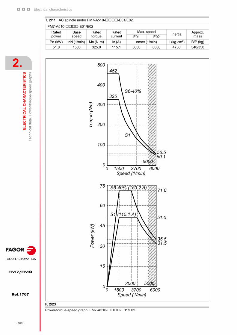
T. 2/11 AC spindle motor FM7-A510--E01/E02.
FM7-A510--E01/E02
Rated power
Basespeed
Ratedtorque
Ratedcurrent
Max. speedInertia Approx.
massE01 E02
Pn (kW) nN (1/min) Mn (N·m) In (A) nmax (1/min) J (kg·cm²) B/P (kg)
51.0 1500 325.0 115.1 5000 6000 4730 340/350
F. 2/23
Power/torque-speed graph. FM7-A510--E01/E02.
500
400
300
200
100
0
Tor
que
(Nm
)
Speed (1/min)0 1500
5000
60003700
S6-40%
S1
452
325
50.156.5
S6-40% (153.2 A)71.0
51.0
35.531.5
Po
wer
(kW
)
S1 (115.1 A)
75
Speed (1/min)0 1500 60003700
5000
60
45
30
15
03000
Electrical characteristics
EL
EC
TR
ICA
L C
HA
RA
CT
ER
IST
ICS
Tec
hnic
al d
ata.
Po
we
r/to
rque
-spe
ed g
rap
hs
2.
Ref.1707
· 51 ·
FM7/FM9
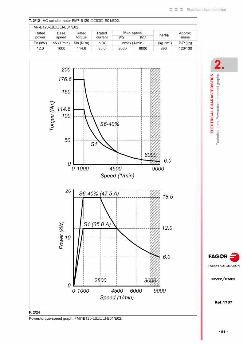
T. 2/12 AC spindle motor FM7-B120--E01/E02.
FM7-B120--E01/E02
Rated power
Basespeed
Ratedtorque
Ratedcurrent
Max. speedInertia Approx.
massE01 E02
Pn (kW) nN (1/min) Mn (N·m) In (A) nmax (1/min) J (kg·cm²) B/P (kg)
12.0 1000 114.6 35.0 8000 9000 890 120/130
F. 2/24
Power/torque-speed graph. FM7-B120--E01/E02.
Speed (1/min)0 1000 90004500
Tor
que
(N
m)
200
150
100
50
0
176.6
114.6
S6-40%
S1
80006.0
S6-40% (47.5 A)
S1 (35.0 A)
0 1000 90004500 6000
2800 8000
Speed (1/min)
18.520
12.0
10
0
Po
wer
(kW
)
6.0
Electrical characteristics
2.
EL
EC
TR
ICA
L C
HA
RA
CT
ER
IST
ICS
Tec
hnic
al d
ata.
Po
we
r/to
rque
-spe
ed g
rap
hs
74
Ref.1707
FM7/FM9
· 52 ·
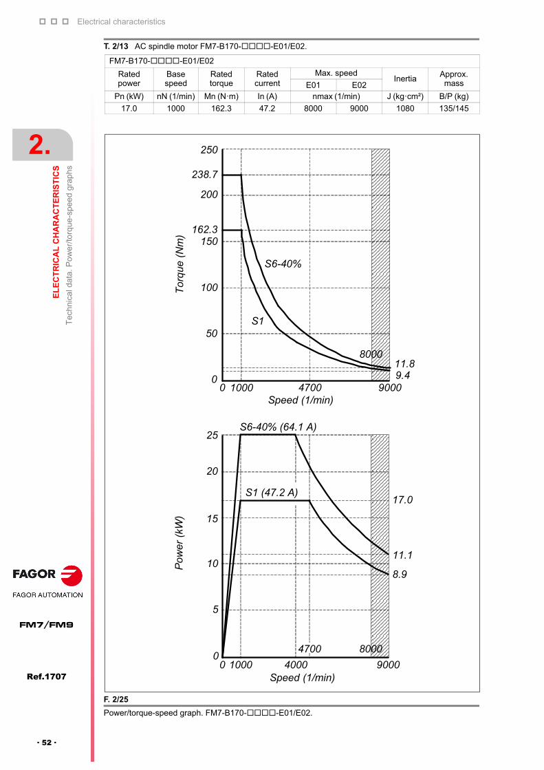
T. 2/13 AC spindle motor FM7-B170--E01/E02.
FM7-B170--E01/E02
Rated power
Basespeed
Ratedtorque
Ratedcurrent
Max. speedInertia Approx.
massE01 E02Pn (kW) nN (1/min) Mn (N·m) In (A) nmax (1/min) J (kg·cm²) B/P (kg)
17.0 1000 162.3 47.2 8000 9000 1080 135/145
F. 2/25
Power/torque-speed graph. FM7-B170--E01/E02.
Tor
que
(Nm
)
250
238.7
200
162.3150
100
50
0
S6-40%
S1
Speed (1/min)0 1000 90004700
8000
0 1000 90004000
4700
Speed (1/min)
8000
S6-40% (64.1 A)
S1 (47.2 A)
11.1
8.9
9.411.8
25
20
17.0
15
Pow
er (
kW)
10
5
0

Electrical characteristics
EL
EC
TR
ICA
L C
HA
RA
CT
ER
IST
ICS
Tec
hnic
al d
ata.
Po
we
r/to
rque
-spe
ed g
rap
hs
2.
Ref.1707
· 53 ·
FM7/FM9
T. 2/14 AC spindle motor FM7-B220--E01.
FM7-B220--E01
Rated power
Basespeed
Ratedtorque
Ratedcurrent
Max. speedInertia Approx.
massE01 E02
Pn (kW) nN (1/min) Mn (N·m) In (A) nmax (1/min) J (kg·cm²) B/P (kg)
22.0 1000 210.0 64.9 6500 - 2310 220/230
F. 2/26
Power/torque-speed graph. FM7-B220--E01.
Tor
que
(N
m)
400
315.1
Speed (1/min)0 1000 65004000
5800
S6-40%
S1
210.0
300
200
100
0
S6-40% (89.5 A)
S1 (64.9 A)
40
30
20
10
0
33.0
22.0
Speed (1/min)0 1000 65004000
5800
Pow
er
(kW
)
32.3

Electrical characteristics
2.
EL
EC
TR
ICA
L C
HA
RA
CT
ER
IST
ICS
Tec
hnic
al d
ata.
Po
we
r/to
rque
-spe
ed g
rap
hs
74
Ref.1707
FM7/FM9
· 54 ·
T. 2/15 AC spindle motor FM7-B280--E01.
FM7-B280--E01
Rated power
Basespeed
Ratedtorque
Ratedcurrent
Max. speedInertia
Approx.massE01 E02
Pn (kW) nN (1/min) Mn (N·m) In (A) nmax (1/min) J (kg·cm²) B/P (kg)
28.0 1000 267.4 78.2 6500 - 2660 250/260
F. 2/27
Power/torque-speed graph. FM7-B280--E01.
401.1
267.4
300
400
S6-40%
S1
0
100
200
Tor
que
(N
m)
Speed (1/min)0 1000 65004000
Speed (1/min)0 1000 65004000
Pow
er (
kW)
S6-40% (109.0 A)
S1 (78.2 A)
50
4042.0
28.027.0
30
20
10
06250
41.139.7

Electrical characteristics
EL
EC
TR
ICA
L C
HA
RA
CT
ER
IST
ICS
Tec
hnic
al d
ata.
Po
we
r/to
rque
-spe
ed g
rap
hs
2.
Ref.1707
· 55 ·
FM7/FM9
T. 2/16 AC spindle motor FM7-C215--E01/E02.
FM7-C215--E01/E02
Rated power
Basespeed
Ratedtorque
Ratedcurrent
Max. speedInertia Approx.
massE01 E02Pn (kW) nN (1/min) Mn (N·m) In (A) nmax (1/min) J (kg·cm²) B/P (kg)
21.5 500 410.6 87.8 5000 6000 4730 340/350
F. 2/28
Power/torque-speed graph. FM7-C215--E01/E02.
553.9
500
410.6400
300
200
100
0500 60005000
S6-40%
S1
Speed (1/min)
Tor
que
(N
m)
25.626.9
S6-40% (114.7 A)
S1 (87.8 A)
29.0
21.5
16.916.1
30
20
10
0
Pow
er
(kW
)
Speed (1/min)500 60003500 5000
4500

Electrical characteristics
2.
EL
EC
TR
ICA
L C
HA
RA
CT
ER
IST
ICS
Tec
hnic
al d
ata.
Po
we
r/to
rque
-spe
ed g
rap
hs
74
Ref.1707
FM7/FM9
· 56 ·
T. 2/17 AC spindle motor FM7-C270--E01/E02.
FM7-C270--E01/E02
Rated power
Basespeed
Ratedtorque
Ratedcurrent
Max. speedInertia
Approx.massE01 E02
Pn (kW) nN (1/min) Mn (N·m) In (A) nmax (1/min) J (kg·cm²) B/P (kg)
27.0 500 515.7 116.9 5000 6000 5840 380/390
F. 2/29
Power/torque-speed graph. FM7-C270--E01/E02.
706.6
515.7
Tor
que
(Nm
)
750
600
450
300
5000
S6-40%
S1
60005000Speed (1/min)
S6-40% (153.2 A)
S1 (116.9 A)
Po
wer
(kW
)
36.6
150
37.0
27.0
23.0
40
30
20
10
0500 60005000
Speed (1/min)
3900
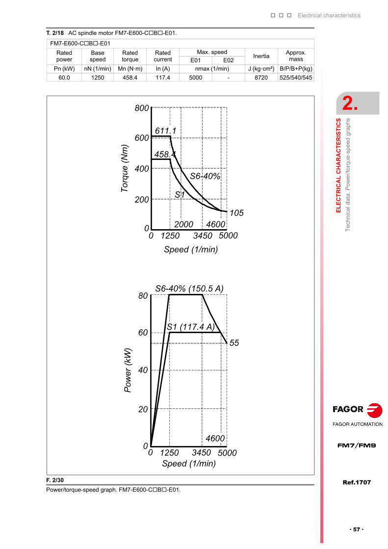
Electrical characteristics
EL
EC
TR
ICA
L C
HA
RA
CT
ER
IST
ICS
Tec
hnic
al d
ata.
Po
we
r/to
rque
-spe
ed g
rap
hs
2.
Ref.1707
· 57 ·
FM7/FM9
T. 2/18 AC spindle motor FM7-E600-CB-E01.
FM7-E600-CB-E01
Rated power
Basespeed
Ratedtorque
Ratedcurrent
Max. speedInertia
Approx.massE01 E02
Pn (kW) nN (1/min) Mn (N·m) In (A) nmax (1/min) J (kg·cm²) B/P/B+P(kg)
60.0 1250 458.4 117.4 5000 - 8720 525/540/545
F. 2/30
Power/torque-speed graph. FM7-E600-CB-E01.
458.4
To
rque
(N
m)
800
600
400
12500
S6-40%
S1
5000
Speed (1/min)
105
200
S6-40% (150.5 A)
S1 (117.4 A)
Pow
er (
kW)
55
80
60
40
20
01250 5000Speed (1/min)
3450
4600
20003450
4600
611.1
0
0

Electrical characteristics
2.
EL
EC
TR
ICA
L C
HA
RA
CT
ER
IST
ICS
Tec
hnic
al d
ata.
Po
we
r/to
rque
-spe
ed g
rap
hs
74
Ref.1707
FM7/FM9
· 58 ·
2.5.2 FM9-XXXX-C5CX-E01-X series
T. 2/19 AC spindle motor FM9-B037-C5C-E01.
FM9-B037-C5C-E01
Rated power
Basespeed
Ratedtorque
Ratedcurrent
Max. speedInertia Approx.
massE01 E02Pn (kW) nN (1/min) Mn (N·m) In (A) nmax (1/min) J (kg·cm²) B+P (kg)
37 1000 350.0 74.7 5000 - 3000 265
F. 2/31
Power/torque-speed graph. FM9-B037-C5C-E01.
torq
ue (
N·m
)426.0
S1
70.0
0 500010000
4000
85.2
S6-40%
80
160
240
320
400
480
350.0
pow
er (
kW)
10
0
50
60
20
30
40
0 50001000
4000
S1 (74.7 A)
S6-40% (89.7 A)
37.0
45.0
2000 3000
2000 3000
speed (1/min)
speed (1/min)
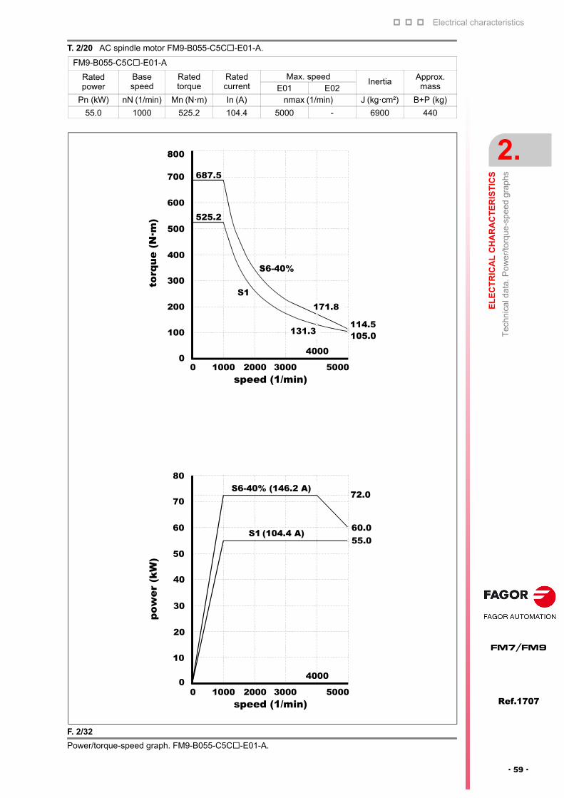
Electrical characteristics
EL
EC
TR
ICA
L C
HA
RA
CT
ER
IST
ICS
Tec
hnic
al d
ata.
Po
we
r/to
rque
-spe
ed g
rap
hs
2.
Ref.1707
· 59 ·
FM7/FM9
T. 2/20 AC spindle motor FM9-B055-C5C-E01-A.
FM9-B055-C5C-E01-A
Rated power
Basespeed
Ratedtorque
Ratedcurrent
Max. speedInertia Approx.
massE01 E02Pn (kW) nN (1/min) Mn (N·m) In (A) nmax (1/min) J (kg·cm²) B+P (kg)
55.0 1000 525.2 104.4 5000 - 6900 440
F. 2/32
Power/torque-speed graph. FM9-B055-C5C-E01-A.
0 50001000
100
400
500
600
2000 30000
200
300
700
800
4000
0 50001000 2000 3000
10
0
40
50
20
30
60
70
80
4000
S1 (104.4 A)
S6-40% (146.2 A)72.0
60.055.0
S1
S6-40%
687.5
525.2
171.8
114.5105.0131.3
torq
ue (
N·m
)
speed (1/min)
pow
er (
kW)
speed (1/min)
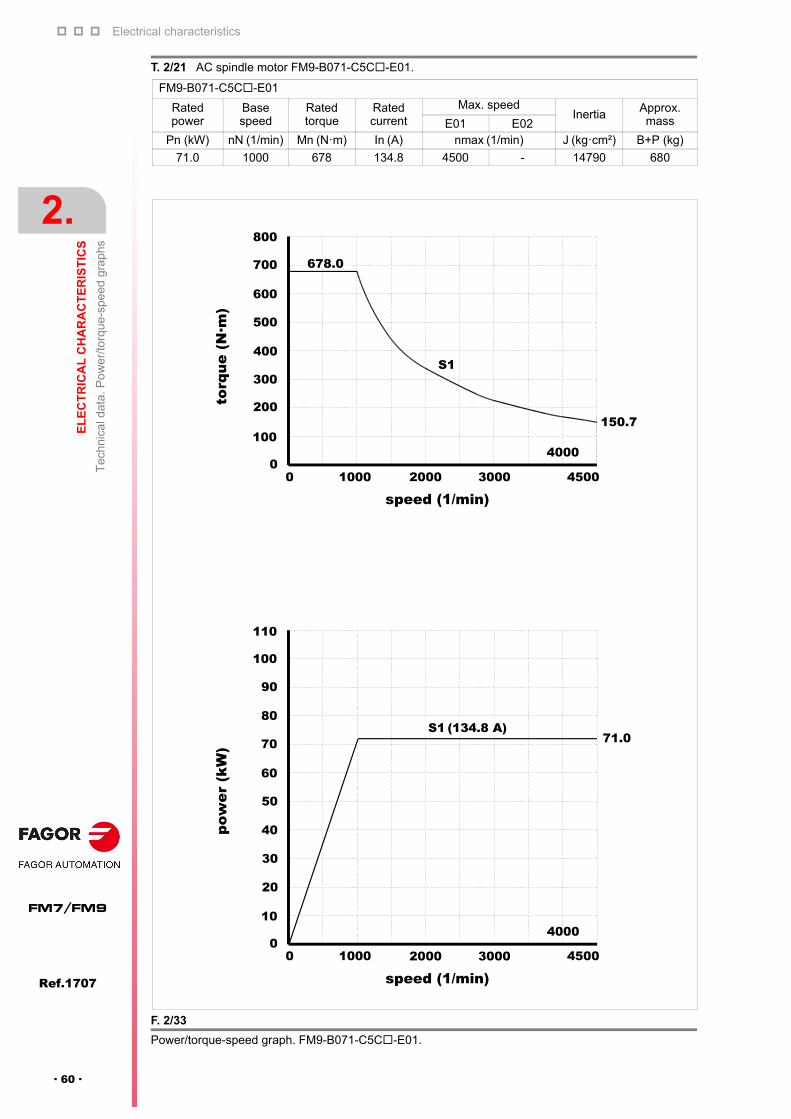
Electrical characteristics
2.
EL
EC
TR
ICA
L C
HA
RA
CT
ER
IST
ICS
Tec
hnic
al d
ata.
Po
we
r/to
rque
-spe
ed g
rap
hs
74
Ref.1707
FM7/FM9
· 60 ·
T. 2/21 AC spindle motor FM9-B071-C5C-E01.
FM9-B071-C5C-E01
Rated power
Basespeed
Ratedtorque
Ratedcurrent
Max. speedInertia Approx.
massE01 E02Pn (kW) nN (1/min) Mn (N·m) In (A) nmax (1/min) J (kg·cm²) B+P (kg)
71.0 1000 678 134.8 4500 - 14790 680
F. 2/33
Power/torque-speed graph. FM9-B071-C5C-E01.
torq
ue (
N·m
)po
wer
(kW
)
678.0
S1
150.7
S1 (134.8 A)71.0
0 45001000
100
0
200
300
400
500
600
700
800
10
0
50
60
70
20
30
40
80
90
100
110
0 45001000
2000 3000
4000
4000
2000 3000
speed (1/min)
speed (1/min)
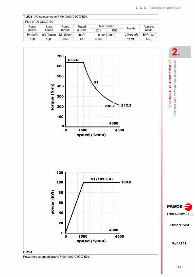
Electrical characteristics
EL
EC
TR
ICA
L C
HA
RA
CT
ER
IST
ICS
Tec
hnic
al d
ata.
Po
we
r/to
rque
-spe
ed g
rap
hs
2.
Ref.1707
· 61 ·
FM7/FM9
T. 2/22 AC spindle motor FM9-A100-C5C-E01.
FM9-A100-C5C-E01
Rated power
Basespeed
Ratedtorque
Ratedcurrent
Max. speedInertia Approx.
massE01 E02
Pn (kW) nN (1/min) Mn (N·m) In (A) nmax (1/min) J (kg·cm²) B+P (kg)
100 1500 636.6 190 4500 - 14790 635
F. 2/34
Power/torque-speed graph. FM9-A100-C5C-E01.
0 45001500
100
04000
S1 (189.9 A)
212.2238.7
S1
636.6
100.0
pow
er (
kW)
torq
ue (
N·m
)
200
300
400
500
600
700
20
0
40
60
80
100
120
0 45001500
4000
speed (1/min)
speed (1/min)
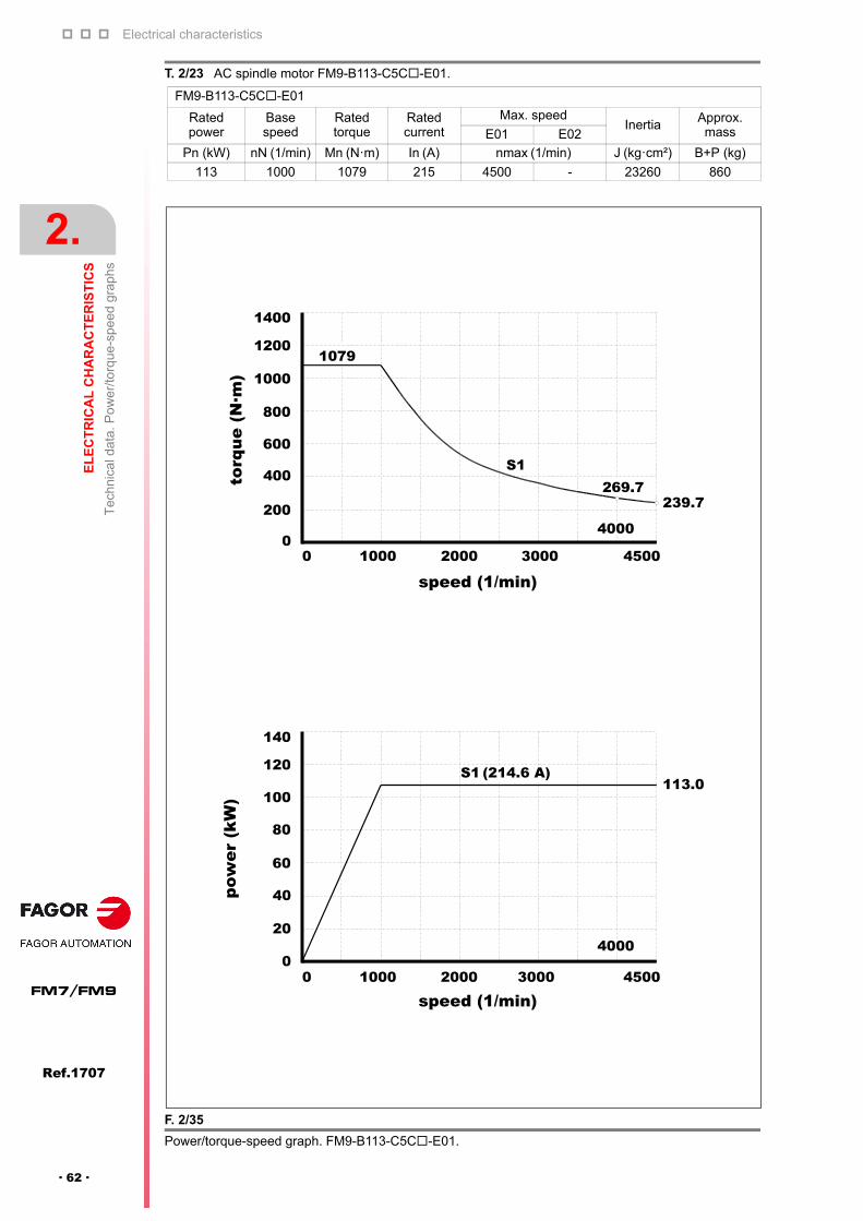
Electrical characteristics
2.
EL
EC
TR
ICA
L C
HA
RA
CT
ER
IST
ICS
Tec
hnic
al d
ata.
Po
we
r/to
rque
-spe
ed g
rap
hs
74
Ref.1707
FM7/FM9
· 62 ·
T. 2/23 AC spindle motor FM9-B113-C5C-E01.
FM9-B113-C5C-E01
Rated power
Basespeed
Ratedtorque
Ratedcurrent
Max. speedInertia Approx.
massE01 E02
Pn (kW) nN (1/min) Mn (N·m) In (A) nmax (1/min) J (kg·cm²) B+P (kg)
113 1000 1079 215 4500 - 23260 860
F. 2/35
Power/torque-speed graph. FM9-B113-C5C-E01.
pow
er (
kW)
torq
ue (
N·m
)
0 45001000
200
0
400
600
800
1000
1200
1400
20
0
40
60
80
100
120
140
0 45001000
239.7
4000
269.7
1079
S1
4000
S1 (214.6 A)113.0
2000 3000
2000 3000
speed (1/min)
speed (1/min)
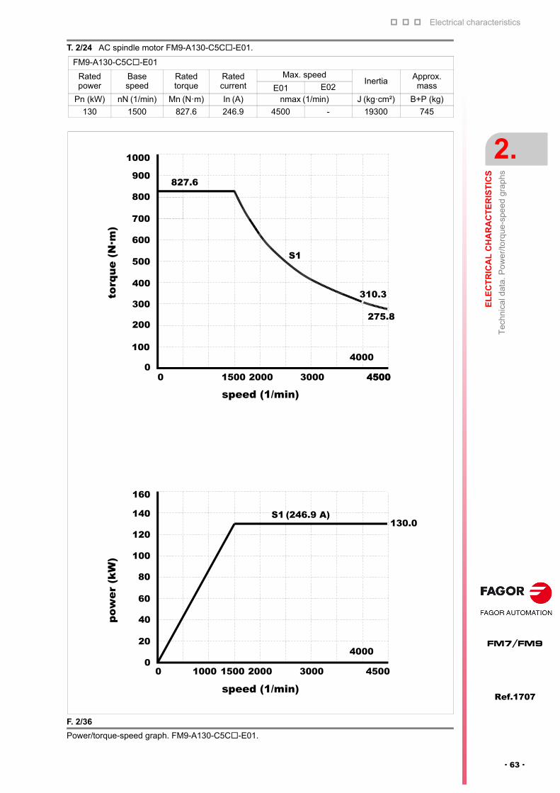
Electrical characteristics
EL
EC
TR
ICA
L C
HA
RA
CT
ER
IST
ICS
Tec
hnic
al d
ata.
Po
we
r/to
rque
-spe
ed g
rap
hs
2.
Ref.1707
· 63 ·
FM7/FM9
T. 2/24 AC spindle motor FM9-A130-C5C-E01.
FM9-A130-C5C-E01
Rated power
Basespeed
Ratedtorque
Ratedcurrent
Max. speedInertia Approx.
massE01 E02
Pn (kW) nN (1/min) Mn (N·m) In (A) nmax (1/min) J (kg·cm²) B+P (kg)
130 1500 827.6 246.9 4500 - 19300 745
F. 2/36
Power/torque-speed graph. FM9-A130-C5C-E01.
S1
S1 (246.9 A)130.0
4000
0 45001000 30001500 2000
20
0
40
60
80
100
120
140
160
pow
er (
kW)
torq
ue (
N·m
)
100
0
200
300
400
500
600
700
800
900
1000
275.8
310.3
0 45001500 2000 3000 4500
4000
827.6
speed (1/min)
speed (1/min)
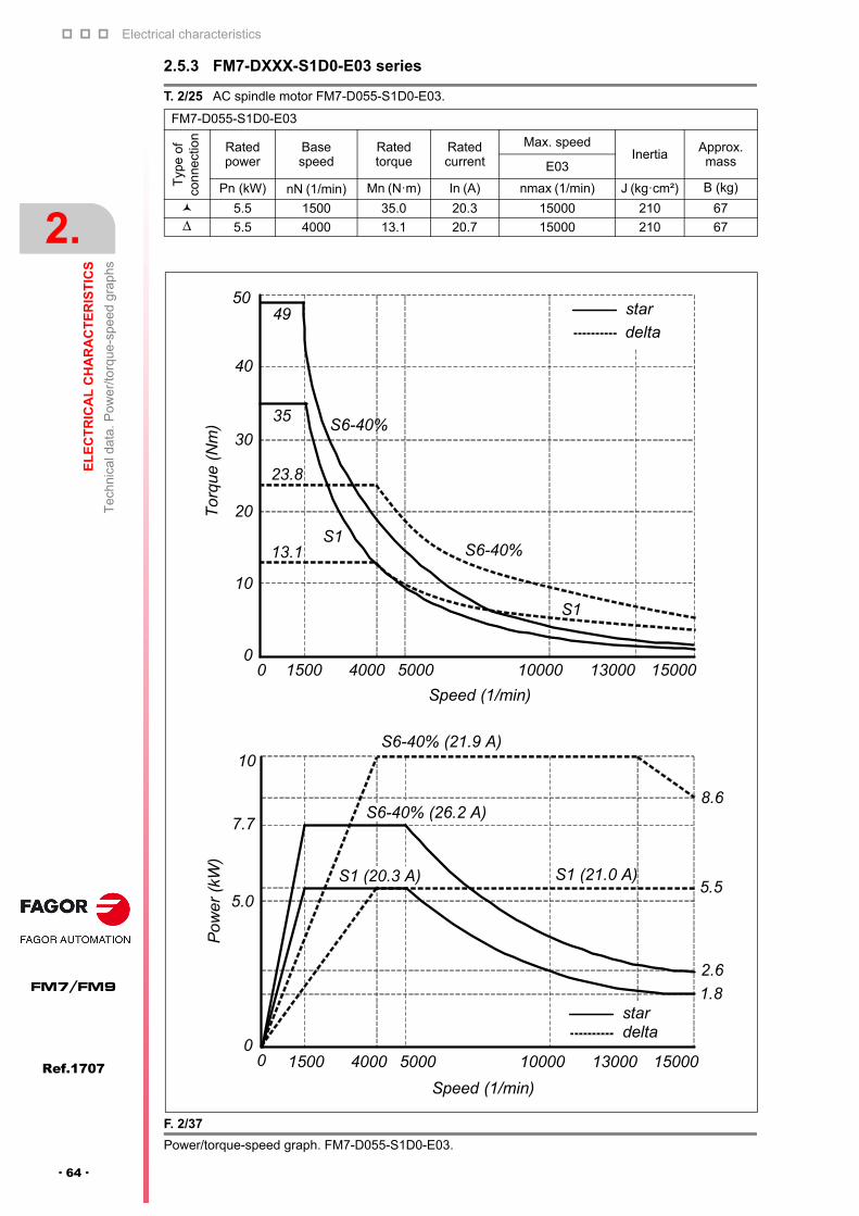
Electrical characteristics
2.
EL
EC
TR
ICA
L C
HA
RA
CT
ER
IST
ICS
Tec
hnic
al d
ata.
Po
we
r/to
rque
-spe
ed g
rap
hs
74
Ref.1707
FM7/FM9
· 64 ·
2.5.3 FM7-DXXX-S1D0-E03 series
T. 2/25 AC spindle motor FM7-D055-S1D0-E03.
FM7-D055-S1D0-E03
Typ
e of
co
nne
ctio
n
Ratedpower
Basespeed
Ratedtorque
Ratedcurrent
Max. speedInertia Approx.
massE03
Pn (kW) nN (1/min) Mn (N·m) In (A) nmax (1/min) J (kg·cm²) B (kg)
5.5 1500 35.0 20.3 15000 210 67 5.5 4000 13.1 20.7 15000 210 67
F. 2/37
Power/torque-speed graph. FM7-D055-S1D0-E03.
Tor
que
(Nm
)
5049
40
30
35
23.8
13.1
20
10
S6-40%
S6-40%
S1
00 1500 4000 5000 10000 13000 15000
Speed (1/min)
S1
S6-40% (21.9 A)
S6-40% (26.2 A)
S1 (21.0 A)S1 (20.3 A)
8.6
5.5
2.6
1.8
0 1500 4000 5000 10000 13000 15000
Speed (1/min)
Pow
er (
kW)
10
7.7
stardelta
5.0
0
star
delta

Electrical characteristics
EL
EC
TR
ICA
L C
HA
RA
CT
ER
IST
ICS
Tec
hnic
al d
ata.
Po
we
r/to
rque
-spe
ed g
rap
hs
2.
Ref.1707
· 65 ·
FM7/FM9
T. 2/26 AC spindle motor FM7-D075-S1D0-E03.
FM7-D075-S1D0-E03
Typ
e o
f co
nnec
tion
Ratedpower
Basespeed
Ratedtorque
Ratedcurrent
Max. speedInertia Approx.
massE03
Pn (kW) nN (1/min) Mn (N·m) In (A) nmax. (1/min) J (kg·cm²) B (kg)
7.5 1500 47.7 26.5 15000 260 74 7.5 4000 17.9 25.8 15000 260 74
F. 2/38
Power/torque-speed graph. FM7-D075-S1D0-E03.
7070
60
50
47.7S6-40%
Tor
que
(Nm
) 40
30
20
10
00 1500 4000 6000 10000 15000
Speed (1/min)
S1
17.9
31.0
S6-40%
S1
4.4
3.0
S1 (26.5 A) S1 (25.8 A)
S6-40% (35.7 A)
S6-40% (34.5 A)
Po
wer
(kW
)
15
13
11
0 1500
6000
10000 15000
Speed (1/min)
5000
4000
stardelta
10
7.5
5
0
stardelta
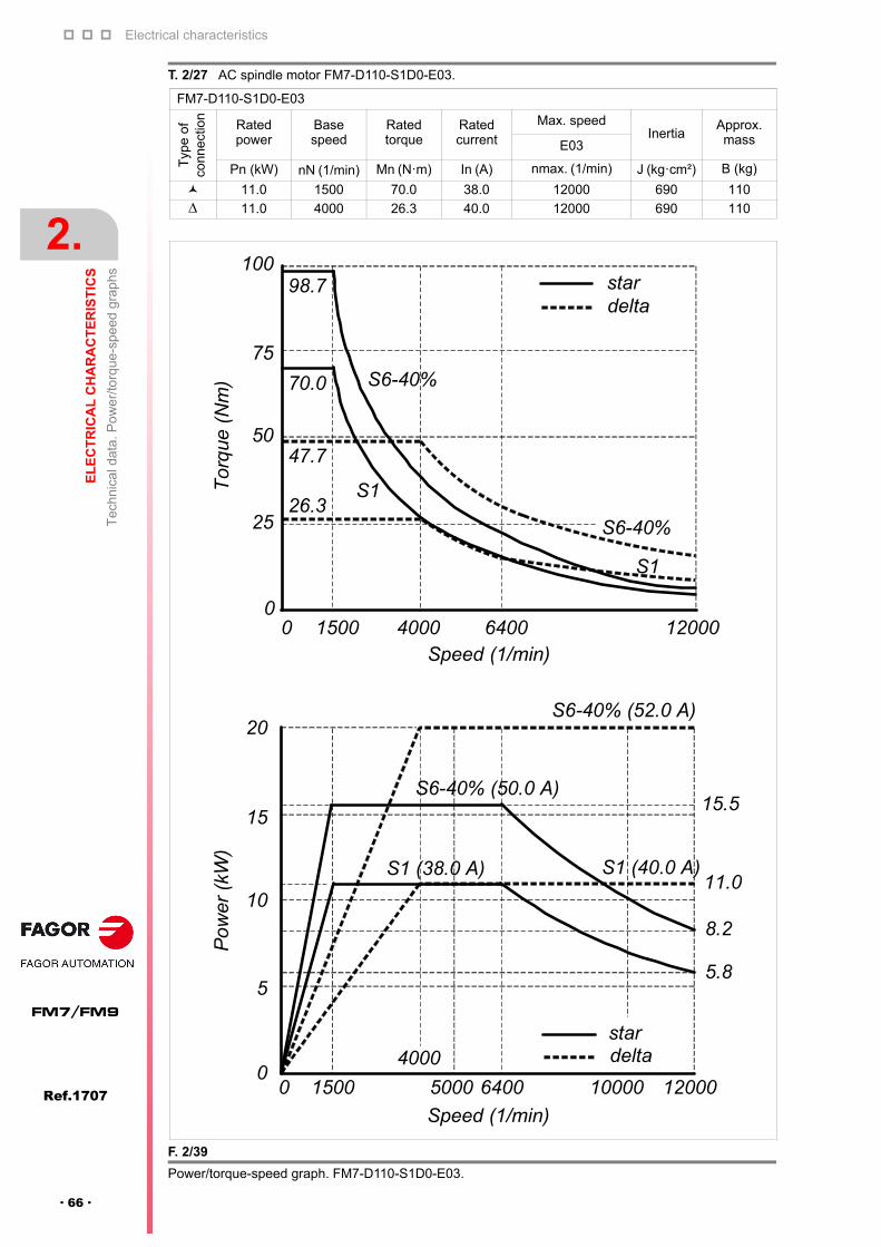
Electrical characteristics
2.
EL
EC
TR
ICA
L C
HA
RA
CT
ER
IST
ICS
Tec
hnic
al d
ata.
Po
we
r/to
rque
-spe
ed g
rap
hs
74
Ref.1707
FM7/FM9
· 66 ·
T. 2/27 AC spindle motor FM7-D110-S1D0-E03.
FM7-D110-S1D0-E03
Typ
e o
f co
nnec
tion
Ratedpower
Basespeed
Ratedtorque
Ratedcurrent
Max. speedInertia
Approx. massE03
Pn (kW) nN (1/min) Mn (N·m) In (A) nmax. (1/min) J (kg·cm²) B (kg)
11.0 1500 70.0 38.0 12000 690 110 11.0 4000 26.3 40.0 12000 690 110
F. 2/39
Power/torque-speed graph. FM7-D110-S1D0-E03.
100
75
98.7
S6-40%70.0
47.7
26.3
Tor
que
(N
m)
50
25
00 1500 4000 6400 12000
Speed (1/min)
S6-40%
S1
S1
stardelta
Po
wer
(kW
)
20
stardelta
Speed (1/min)
15
S6-40% (52.0 A)
S6-40% (50.0 A)15.5
11.0
8.2
5.8
S1 (40.0 A)S1 (38.0 A)
0 1500 5000 6400 12000
4000
10000
10
5
0
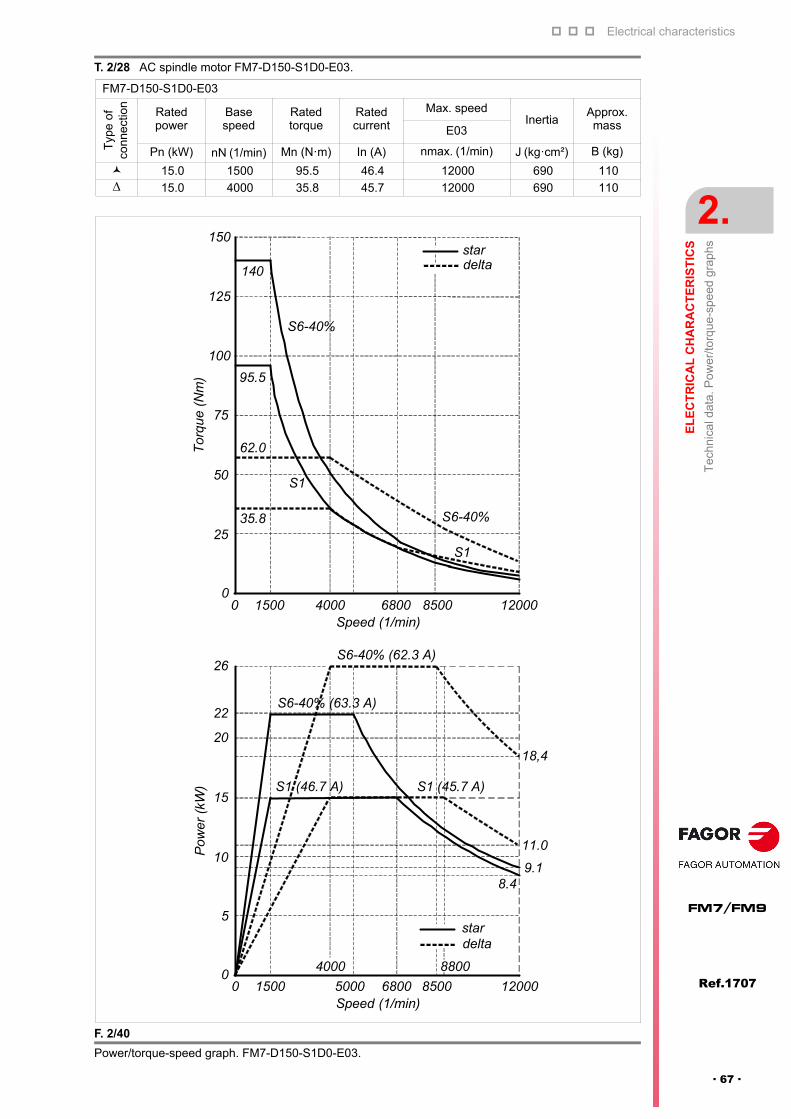
Electrical characteristics
EL
EC
TR
ICA
L C
HA
RA
CT
ER
IST
ICS
Tec
hnic
al d
ata.
Po
we
r/to
rque
-spe
ed g
rap
hs
2.
Ref.1707
· 67 ·
FM7/FM9
T. 2/28 AC spindle motor FM7-D150-S1D0-E03.
FM7-D150-S1D0-E03
Typ
e o
f co
nnec
tion
Ratedpower
Basespeed
Ratedtorque
Ratedcurrent
Max. speedInertia
Approx. massE03
Pn (kW) nN (1/min) Mn (N·m) In (A) nmax. (1/min) J (kg·cm²) B (kg)
15.0 1500 95.5 46.4 12000 690 110 15.0 4000 35.8 45.7 12000 690 110
F. 2/40
Power/torque-speed graph. FM7-D150-S1D0-E03.
150
140
95.5
125
100
75
62.0
35.8
50
25
0
Tor
que
(Nm
)
S6-40%
S6-40%
S1
S1
0 1500 4000 6800 12000Speed (1/min)
stardelta
8500
S6-40% (62.3 A)
S6-40% (63.3 A)
S1 (45.7 A)S1 (46.7 A)
18,4
11.0
9.18.4
Pow
er (
kW)
26
22
20
15
10
5
00 1500 5000 6800 12000
Speed (1/min)
stardelta
8500
4000 8800

Electrical characteristics
2.
EL
EC
TR
ICA
L C
HA
RA
CT
ER
IST
ICS
Tec
hnic
al d
ata.
Po
we
r/to
rque
-spe
ed g
rap
hs
74
Ref.1707
FM7/FM9
· 68 ·
T. 2/29 AC spindle motor FM7-D185-S1D0-E03.
FM7-D185-S1D0-E03
Typ
e o
f co
nnec
tion
Ratedpower
Basespeed
Ratedtorque
Ratedcurrent
Max. speedInertia Approx.
massE03
Pn (kW) nN (1/min) Mn (N·m) In (A) nmax. (1/min) J (kg·cm²) B (kg)
18.5 1500 117.8 49.2 12000 890 135 18.5 4000 44.2 49.2 12000 890 135
F. 2/41
Power/torque-speed graph. FM7-D185-S1D0-E03.
175
165.5
150
125117.8
100
S6-40%
76.475
50
25
Tor
que
(Nm
)
44.2
S1
00 1500 4000
7500
12000Speed (1/min)
stardelta
8000
S1
S6-40%
S6-40% (70.5 A)
26.0
32
30
S6-40% (63.0 A)
25
2018.5
15
11.6
10
5
0
S1 (49.2 A) S1 (49.2 A)
0 1500 4000 12000Speed (1/min)
stardelta
7500
5300
Pow
er (
kW)
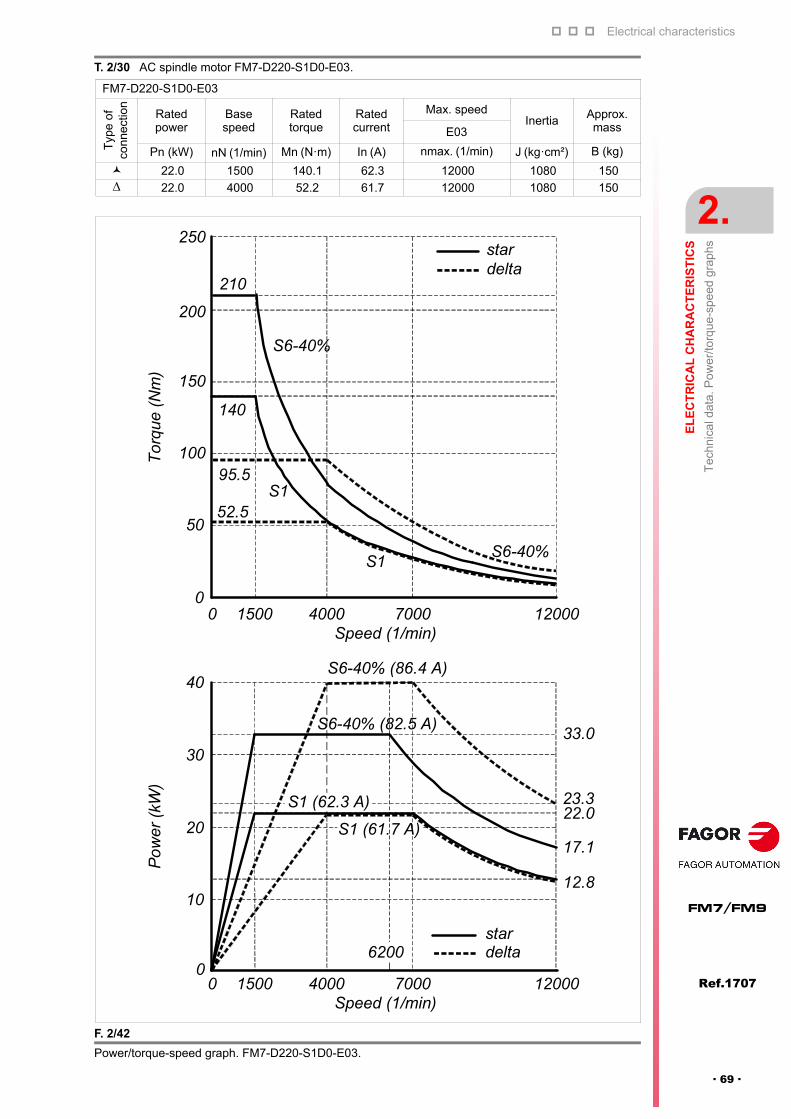
Electrical characteristics
EL
EC
TR
ICA
L C
HA
RA
CT
ER
IST
ICS
Tec
hnic
al d
ata.
Po
we
r/to
rque
-spe
ed g
rap
hs
2.
Ref.1707
· 69 ·
FM7/FM9
T. 2/30 AC spindle motor FM7-D220-S1D0-E03.
FM7-D220-S1D0-E03
Typ
e o
f co
nnec
tion
Ratedpower
Basespeed
Ratedtorque
Ratedcurrent
Max. speedInertia Approx.
massE03
Pn (kW) nN (1/min) Mn (N·m) In (A) nmax. (1/min) J (kg·cm²) B (kg)
22.0 1500 140.1 62.3 12000 1080 150 22.0 4000 52.2 61.7 12000 1080 150
F. 2/42
Power/torque-speed graph. FM7-D220-S1D0-E03.
250
210
200
S6-40%
S6-40%
0 1500 4000 12000Speed (1/min)
stardelta
7000
150
140
10095.5
50
0
52.5
S1
To
rqu
e (N
m)
S1
40
33.0
23.322.0
17.1
12.8
S6-40% (86.4 A)
S6-40% (82.5 A)
S1 (62.3 A)
S1 (61.7 A)
Po
wer
(kW
)
30
20
0 1500 4000 12000Speed (1/min)
stardelta
7000
6200
10
0

Electrical characteristics
2.
EL
EC
TR
ICA
L C
HA
RA
CT
ER
IST
ICS
Tec
hnic
al d
ata.
Po
we
r/to
rque
-spe
ed g
rap
hs
74
Ref.1707
FM7/FM9
· 70 ·
2.5.4 FM7-DXXX-S1D0-HS3 series
T. 2/31 AC spindle motor FM7-D075-S1D0-HS3.
FM7-D075-S1D0-HS3
Typ
e of
co
nne
ctio
n
Ratedpower
Basespeed
Ratedtorque
Ratedcurrent
Max. speedInertia Approx.
massHS3
Pn (kW) nN (1/min) Mn (N·m) In (A) nmax (1/min) J (kg·cm²) B (kg)
7.5 1500 47.7 26.5 15000 260 77 7.5 4000 17.9 25.8 15000 260 77
F. 2/43
Power/torque-speed graph. FM7-D075-S1D0-HS3.
7070
60
50
47.7S6-40%
Tor
que
(Nm
) 40
30
20
10
00 1500 4000 6000 10000 15000
Speed (1/min)
S1
17.9
31.0
S6-40%
S1
4.4
3.0
S1 (26.5 A) S1 (25.8 A)
S6-40% (35.7 A)
S6-40% (34.5 A)
Pow
er
(kW
)
15
13
11
0 1500
6000
10000 15000
Speed (1/min)
5000
4000
star
delta
10
7.5
5
0
star
delta
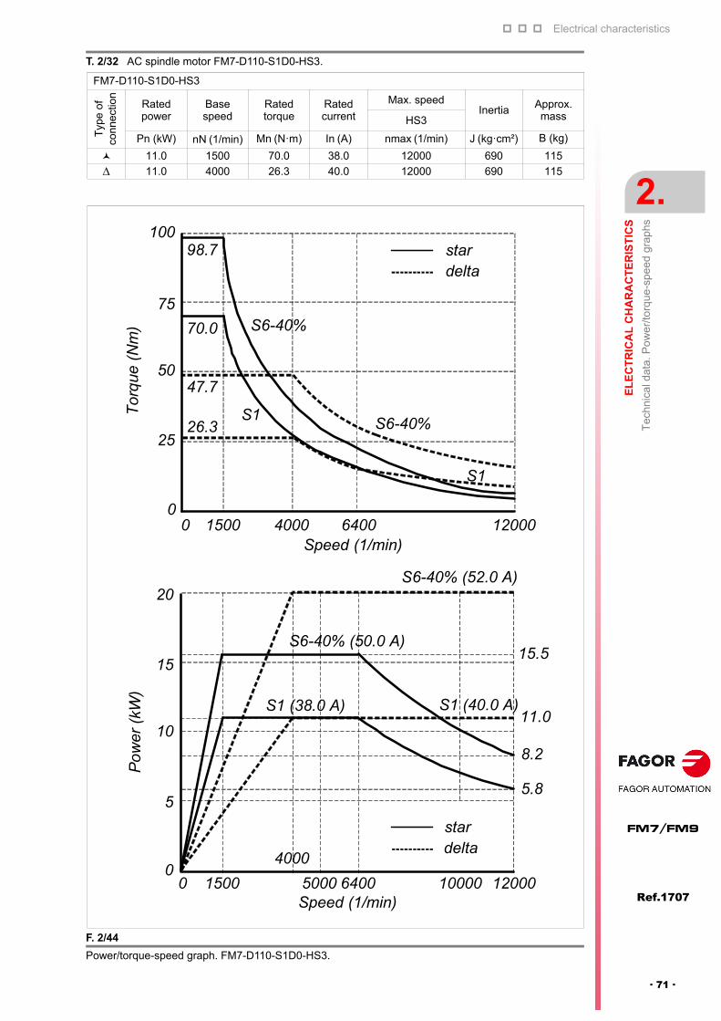
Electrical characteristics
EL
EC
TR
ICA
L C
HA
RA
CT
ER
IST
ICS
Tec
hnic
al d
ata.
Po
we
r/to
rque
-spe
ed g
rap
hs
2.
Ref.1707
· 71 ·
FM7/FM9
T. 2/32 AC spindle motor FM7-D110-S1D0-HS3.
FM7-D110-S1D0-HS3
Typ
e o
f co
nnec
tion
Ratedpower
Basespeed
Ratedtorque
Ratedcurrent
Max. speedInertia Approx.
massHS3
Pn (kW) nN (1/min) Mn (N·m) In (A) nmax (1/min) J (kg·cm²) B (kg)
11.0 1500 70.0 38.0 12000 690 115
11.0 4000 26.3 40.0 12000 690 115
F. 2/44
Power/torque-speed graph. FM7-D110-S1D0-HS3.
100
75
98.7
S6-40%70.0
47.7
26.3
Tor
que
(N
m)
50
25
00 1500 4000 6400 12000
Speed (1/min)
S6-40%
S1
S1
stardelta
Po
wer
(kW
)
20
Speed (1/min)
15
S6-40% (52.0 A)
S6-40% (50.0 A)15.5
11.0
8.2
5.8
S1 (40.0 A)S1 (38.0 A)
0 1500 5000 6400 12000
4000
10000
10
5
0
stardelta
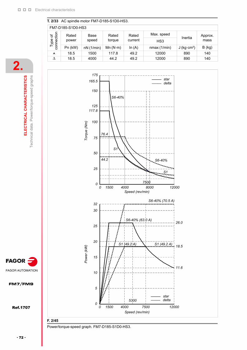
Electrical characteristics
2.
EL
EC
TR
ICA
L C
HA
RA
CT
ER
IST
ICS
Tec
hnic
al d
ata.
Po
we
r/to
rque
-spe
ed g
rap
hs
74
Ref.1707
FM7/FM9
· 72 ·
T. 2/33 AC spindle motor FM7-D185-S1D0-HS3.
FM7-D185-S1D0-HS3
Typ
e o
f co
nnec
tion
Ratedpower
Basespeed
Ratedtorque
Ratedcurrent
Max. speedInertia
Approx. massHS3
Pn (kW) nN (1/min) Mn (N·m) In (A) nmax (1/min) J (kg·cm²) B (kg)
18.5 1500 117.8 49.2 12000 890 140 18.5 4000 44.2 49.2 12000 890 140
F. 2/45
Power/torque-speed graph. FM7-D185-S1D0-HS3.
175
165.5
150
125117.8
100
S6-40%
76.475
50
25
Tor
que
(N
m)
44.2
S1
00 1500 4000
7500
12000Speed (rev/min)
stardelta
8000
S1
S6-40%
S6-40% (70.5 A)
26.0
32
30
S6-40% (63.0 A)
25
2018.5
15
11.6
10
5
0
S1 (49.2 A) S1 (49.2 A)
0 1500 4000 12000
Speed (rev/min)
stardelta
7500
5300
Pow
er (
kW)
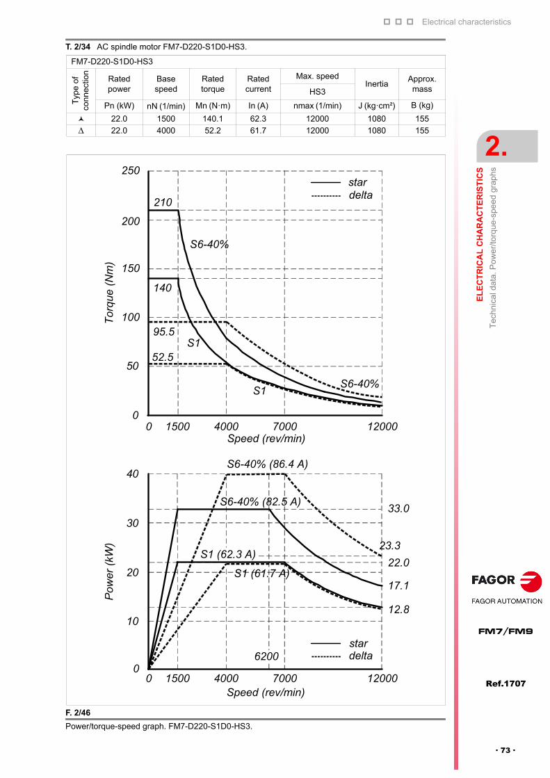
Electrical characteristics
EL
EC
TR
ICA
L C
HA
RA
CT
ER
IST
ICS
Tec
hnic
al d
ata.
Po
we
r/to
rque
-spe
ed g
rap
hs
2.
Ref.1707
· 73 ·
FM7/FM9
T. 2/34 AC spindle motor FM7-D220-S1D0-HS3.
FM7-D220-S1D0-HS3
Typ
e o
f co
nnec
tion
Ratedpower
Basespeed
Ratedtorque
Ratedcurrent
Max. speedInertia
Approx. massHS3
Pn (kW) nN (1/min) Mn (N·m) In (A) nmax (1/min) J (kg·cm²) B (kg)
22.0 1500 140.1 62.3 12000 1080 155
22.0 4000 52.2 61.7 12000 1080 155
F. 2/46
Power/torque-speed graph. FM7-D220-S1D0-HS3.
250
210
200
S6-40%
S6-40%
0 1500 4000 12000Speed (rev/min)
stardelta
7000
150
140
10095.5
50
0
52.5
S1
Tor
que
(Nm
)
S1
40
33.0
23.3
22.0
17.1
12.8
S6-40% (86.4 A)
S6-40% (82.5 A)
S1 (62.3 A)
S1 (61.7 A)
Pow
er (
kW)
30
20
0 1500 4000 12000Speed (rev/min)
stardelta
7000
6200
10
0
2.
EL
EC
TR
ICA
L C
HA
RA
CT
ER
IST
ICS
Electrical characteristics
Ref.1707
FM7/FM9
· 74 ·
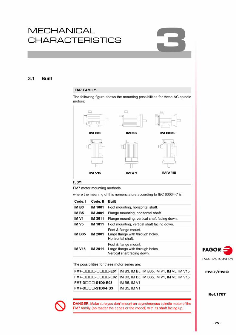
3
Ref.1707
· 75 ·
FM7/FM9
MECHANICAL CHARACTERISTICS
3.1 Built
The following figure shows the mounting possibilities for these AC spindlemotors:
where the meaning of this nomenclature according to IEC 60034-7 is:
The possibilities for these motor series are:
FM7 FAMILY
F. 3/1
FM7 motor mounting methods.
Code. I Code. II Built
IM B3 IM 1001 Foot mounting, horizontal shaft.
IM B5 IM 3001 Flange mounting, horizontal shaft.
IM V1 IM 3011 Flange mounting, vertical shaft facing down.
IM V5 IM 1011 Foot mounting, vertical shaft facing down.
IM B35 IM 2001Foot & flange mount.Large flange with through holes.Horizontal shaft.
IM V15 IM 2011Foot & flange mount. Large flange with through holes.Vertical shaft facing down.
FM7---E01 IM B3, IM B5, IM B35, IM V1, IM V5, IM V15
FM7---E02 IM B3, IM B5, IM B35, IM V1, IM V5, IM V15
FM7-D-S1D0-E03 IM B5, IM V1
FM7-D-S1D0-HS3 IM B5, IM V1
IM B3
IM V5
IM B5
IM V1
IM B35
IM V15
DANGER. Make sure you don't mount an asynchronous spindle motor of theFM7 family (no matter the series or the model) with its shaft facing up.

Mechanical characteristics
3.
ME
CH
AN
ICA
L C
HA
RA
CT
ER
IST
ICS
Bu
ilt
116
Ref.1707
FM7/FM9
· 76 ·
The following figure shows the mounting possibilities for these AC spindlemotors:
where the meaning of this nomenclature according to IEC 60034-7 is:
FM9 FAMILY
F. 3/2
FM9 motor mounting methods.
Code I Code II Built
IM B3 IM 1001 Foot mounting, horizontal shaft.
IM B5 IM 3001 Flange mounting, horizontal shaft.
IM V1 IM 3011 Flange mounting, vertical shaft facing down.
IM V5 IM 1011 Foot mounting, vertical shaft facing down.
IM V3 IM 3031 Flange mounting, vertical shaft facing up.
IM V6 IM 1031 Foot mounting, vertical shaft facing up.
IM B35 IM 2001Foot & flange mount.Large flange with through holes.Horizontal shaft.
IM V15 IM 2011Foot & flange mount. Large flange with through holes.Vertical shaft facing down.
IM V36 IM 2031Foot & flange mount. Large flange with through holes.Vertical shaft facing up.

Mechanical characteristics
ME
CH
AN
ICA
L C
HA
RA
CT
ER
IST
ICS
Lev
el o
f vib
ratio
n
3.
Ref.1707
· 77 ·
FM7/FM9
3.2 Level of vibration
It is not possible to apply a high radial load value (perpendicular) to the motorshaft and obtain high speed and optimum vibration levels. This limitation isbecause the two properties require different designs of bearings and theyconflict with each other.
Hence, the following graphs show the vibration limits for the available standardbalancing degrees.
The following table shows the degrees of vibration for each motor modelwithin its corresponding series.
F. 3/3
Limit values of vibration levels on motors with shaft heights between 110 mmand 132 mm.
F. 3/4
Limit values of vibration levels on motors with shaft heights between 160 mmand 225 mm.
NOTE. Observe that either one or the other of the previous graphs must beconsidered depending on the shaft height of the motor being considered.
Motor shaft height range between 100 and 132 mm
VIBRATION SPECIFICATIONS
Vib
rati
on
sp
eed
lim
it V
rms
(mm
/s)
3.5
V5 degree
S degree
SR degree
3.0
2.5
2.0
1.5
1.0
0.5
0.00 1000 2000 3000 4000 5000 6000 7000 8000 9000 10000 11000 12000
R degree
Motor Speed (min-1)
EuropeanStandard
S degreeR degree
SR degree
AsianStandard
V5 degree
V3 degree
V3 degree
Vib
rati
on
sp
eed
lim
it V
rms
(mm
/s)
0.0
0.5
1.0
1.5
2.0
2.5
3.0
3.5
4.0
4.5Motor shaft height range between 160 and 225 mm
VIBRATION SPECIFICATIONS
0 1000 2000 3000 4000 5000 6000 7000 8000 9000
Motor Speed (min-1)
V5 degree
V10 degree
R degree
S degree
SR degree
EuropeanStandard
S degreeR degreeSR degree
AsianStandard
V10 degreeV5 degree
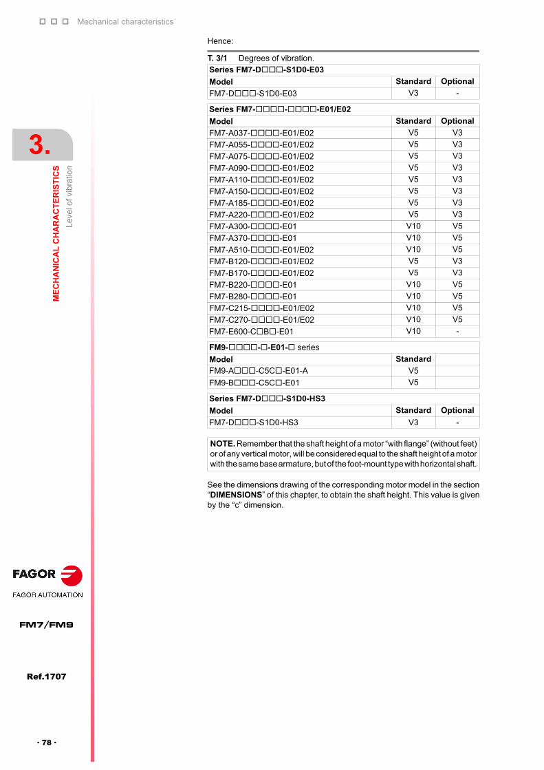
Mechanical characteristics
3.
ME
CH
AN
ICA
L C
HA
RA
CT
ER
IST
ICS
Lev
el o
f vib
ratio
n
116
Ref.1707
FM7/FM9
· 78 ·
Hence:
See the dimensions drawing of the corresponding motor model in the section“DIMENSIONS” of this chapter, to obtain the shaft height. This value is givenby the “c” dimension.
T. 3/1 Degrees of vibration.
Series FM7-D-S1D0-E03
Model Standard Optional
FM7-D-S1D0-E03 V3 -
Series FM7---E01/E02
Model Standard Optional
FM7-A037--E01/E02 V5 V3
FM7-A055--E01/E02 V5 V3
FM7-A075--E01/E02 V5 V3
FM7-A090--E01/E02 V5 V3
FM7-A110--E01/E02 V5 V3
FM7-A150--E01/E02 V5 V3
FM7-A185--E01/E02 V5 V3
FM7-A220--E01/E02 V5 V3
FM7-A300--E01 V10 V5
FM7-A370--E01 V10 V5
FM7-A510--E01/E02 V10 V5
FM7-B120--E01/E02 V5 V3
FM7-B170--E01/E02 V5 V3
FM7-B220--E01 V10 V5
FM7-B280--E01 V10 V5
FM7-C215--E01/E02 V10 V5
FM7-C270--E01/E02 V10 V5
FM7-E600-CB-E01 V10 -
FM9---E01- series
Model Standard
FM9-A-C5C-E01-A V5
FM9-B-C5C-E01 V5
Series FM7-D-S1D0-HS3
Model Standard Optional
FM7-D-S1D0-HS3 V3 -
NOTE. Remember that the shaft height of a motor “with flange” (without feet)or of any vertical motor, will be considered equal to the shaft height of a motorwith the same base armature, but of the foot-mount type with horizontal shaft.
Mechanical characteristics
ME
CH
AN
ICA
L C
HA
RA
CT
ER
IST
ICS
Bal
anc
ing
3.
Ref.1707
· 79 ·
FM7/FM9
3.3 Balancing
For motors with:
Maximum speed nmax < 8000 rev/min, we recommend the shaft to havea keyway and to be balanced halfkey.
When performing the half-key balancing, a rectangular full-length, halfheight keyway as well as a full height, half length keyway are acceptable.The keyway will be centered along the shaft regardless of the option beingconsidered.
Maximum speed nmax 8000 rev/min the shaft should be cylindrical, i.e.keyless and the balancing must be performed in these conditions.

Mechanical characteristics
3.
ME
CH
AN
ICA
L C
HA
RA
CT
ER
IST
ICS
Bea
rings
116
Ref.1707
FM7/FM9
· 80 ·
3.4 Bearings
The useful life of the bearings will be approximately 12000 hours ofcontinuous running and at maximum speed for all the models of FM7 spindlemotors and 5000 hours for FM9 motors.
The references of the bearings located at the shaft end and at the fan endare indicated on the identifications plate stuck on one side of the motor.
For further detail, see section CHARACTERISTICS PLATE of chapter 6.SELECTION in this manual.
When starting the motor up for the first time, run it first trying to:
Gradually increase the speed of the motor from 0 to 70% of themaximum speed in about 20 minutes.
Do not run the motor for too long at its maximum speed.
Watch the temperature values and possible unusual noises.
It may make too much noise at first, in the few initial minutes because thebearings are not evenly lubricated. At the end of this initial running, it willgo back to normal.
NOTE. It is not necessary to lubricate the bearings during the whole periodof the useful life of the bearing indicated earlier. These motors do not havea lubrication system.
MANDATORY. Blows will affect negatively the performance of the motor,hence reducing the useful life of the bearings. Do not strike any part off themotor, especially the extension of the shaft.
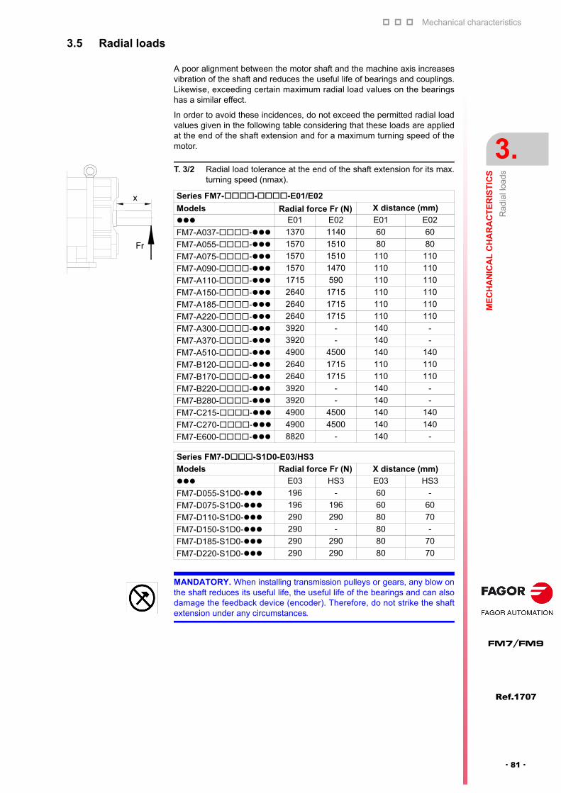
Mechanical characteristics
ME
CH
AN
ICA
L C
HA
RA
CT
ER
IST
ICS
Rad
ial l
oads
3.
Ref.1707
· 81 ·
FM7/FM9
3.5 Radial loads
A poor alignment between the motor shaft and the machine axis increasesvibration of the shaft and reduces the useful life of bearings and couplings.Likewise, exceeding certain maximum radial load values on the bearingshas a similar effect.
In order to avoid these incidences, do not exceed the permitted radial loadvalues given in the following table considering that these loads are appliedat the end of the shaft extension and for a maximum turning speed of themotor.
T. 3/2 Radial load tolerance at the end of the shaft extension for its max.turning speed (nmax).
Series FM7---E01/E02
Models Radial force Fr (N) X distance (mm)
E01 E02 E01 E02
FM7-A037-- 1370 1140 60 60
FM7-A055-- 1570 1510 80 80
FM7-A075-- 1570 1510 110 110
FM7-A090-- 1570 1470 110 110
FM7-A110-- 1715 590 110 110
FM7-A150-- 2640 1715 110 110
FM7-A185-- 2640 1715 110 110
FM7-A220-- 2640 1715 110 110
FM7-A300-- 3920 - 140 -
FM7-A370-- 3920 - 140 -
FM7-A510-- 4900 4500 140 140
FM7-B120-- 2640 1715 110 110
FM7-B170-- 2640 1715 110 110
FM7-B220-- 3920 - 140 -
FM7-B280-- 3920 - 140 -
FM7-C215-- 4900 4500 140 140
FM7-C270-- 4900 4500 140 140
FM7-E600-- 8820 - 140 -
Series FM7-D-S1D0-E03/HS3
Models Radial force Fr (N) X distance (mm)
E03 HS3 E03 HS3
FM7-D055-S1D0- 196 - 60 -
FM7-D075-S1D0- 196 196 60 60
FM7-D110-S1D0- 290 290 80 70
FM7-D150-S1D0- 290 - 80 -
FM7-D185-S1D0- 290 290 80 70
FM7-D220-S1D0- 290 290 80 70
x
Fr
MANDATORY. When installing transmission pulleys or gears, any blow onthe shaft reduces its useful life, the useful life of the bearings and can alsodamage the feedback device (encoder). Therefore, do not strike the shaftextension under any circumstances.

Mechanical characteristics
3.
ME
CH
AN
ICA
L C
HA
RA
CT
ER
IST
ICS
Rad
ial l
oads
116
Ref.1707
FM7/FM9
· 82 ·
3.5.1 “Radial load - turning speed” diagrams
Usually, mechanical elements (spindles) or transmission elements (gearboxes) will be coupled to the end of the motor shaft extension. In dynamicconditions, the motor shaft will be subject to forces due to radial loads. Ifthese dynamic forces exceed a certain limit that the shaft was designed for,its useful life will be reduced due to damage caused by fatigue while it'srunning. Therefore:
FM7---E01/E02 series
DANGER. Make sure that the maximum values of the radial loads applied indynamic conditions on to the motor shaft extension never exceed theadmissible values given by the diagrams depending on the turning speed ofthe shaft.
NOTE. Exceeding the radial load limit value on the shaft will increasemotor vibration and decrease the life span of its bearings and couplings.
F. 3/5
FM7---E01/E02 series. Diagram for maximum radial load asa function of turning speed.
T. 3/3 Particular Fri and Ni values according to motor model.
Series FM7---E01/E02
ModelRadial force Fri (N) Turning speed Ni (1/min)
Fr1 Fr2 Fr3 Fr4 (*) N1 N2 N3 N4 (*)
FM7-A037 1610 1467 1370 1140 5630 7190 9000 12000
FM7-A055 1910 1890 1570 1510 4880 5000 9000 10000
FM7-A075 1990 1890 1570 1510 4310 5965 9000 10000
FM7-A090 1990 1890 1570 1470 4610 5625 9000 10000
FM7-A110 2810 2150 1715 590 1500 4560 9000 10000
FM7-A150 3230 3195 2640 1715 4360 4560 8000 9000
FM7-A185 3880 3000 2640 1715 2340 5265 8000 9000
FM7-A220 3930 2935 2640 1715 1500 6140 8000 9000
FM7-A300 5570 4175 3920 - 1500 5440 6500 -
FM7-A370 5720 4435 3920 - 1640 4385 6500 -
FM7-A510 5720 5390 4900 4500 2960 3510 5000 6000
FM7-B120 3530 3130 2640 1715 2990 5000 8000 9000
FM7-B170 3530 3130 2640 1715 2990 5000 8000 9000
FM7-B220 5720 4610 3920 - 2080 3947 6500 -
FM7-B280 5720 4520 3920 - 2220 4210 6500 -
FM7-C215 5720 5565 4900 4500 3340 3510 5000 6000
FM7-C270 5720 5305 4900 4500 3600 3860 5000 6000FM7-E600 8820 8820 8820 - 1250 3450 5000 -
NOTE. The Fr4 and N4 values are only valid for E02 series motors.
F r
X
N 3 N 4N 2N 1
F r4
Fr
(N)
- R
AD
IAL
LOA
D
n (m in -1 ) - S P E E D
F r3
F r2
F r1
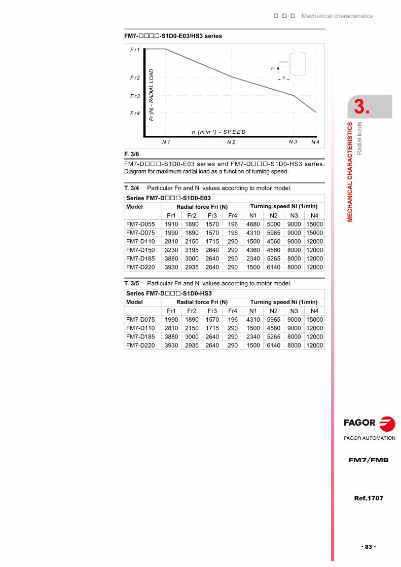
Mechanical characteristics
ME
CH
AN
ICA
L C
HA
RA
CT
ER
IST
ICS
Rad
ial l
oads
3.
Ref.1707
· 83 ·
FM7/FM9
FM7--S1D0-E03/HS3 series
F. 3/6
FM7-D-S1D0-E03 series and FM7-D-S1D0-HS3 series.Diagram for maximum radial load as a function of turning speed.
T. 3/4 Particular Fri and Ni values according to motor model.
Series FM7-D-S1D0-E03Model Radial force Fri (N) Turning speed Ni (1/min)
Fr1 Fr2 Fr3 Fr4 N1 N2 N3 N4
FM7-D055 1910 1890 1570 196 4880 5000 9000 15000
FM7-D075 1990 1890 1570 196 4310 5965 9000 15000
FM7-D110 2810 2150 1715 290 1500 4560 9000 12000
FM7-D150 3230 3195 2640 290 4360 4560 8000 12000
FM7-D185 3880 3000 2640 290 2340 5265 8000 12000
FM7-D220 3930 2935 2640 290 1500 6140 8000 12000
T. 3/5 Particular Fri and Ni values according to motor model.
Series FM7-D-S1D0-HS3Model Radial force Fri (N) Turning speed Ni (1/min)
Fr1 Fr2 Fr3 Fr4 N1 N2 N3 N4
FM7-D075 1990 1890 1570 196 4310 5965 9000 15000
FM7-D110 2810 2150 1715 290 1500 4560 9000 12000
FM7-D185 3880 3000 2640 290 2340 5265 8000 12000
FM7-D220 3930 2935 2640 290 1500 6140 8000 12000
F r
X
N 3 N 4N 2N 1
F r4
Fr
(N)
- R
AD
IAL
LOA
D
n (m in -1 ) - S P E E D
F r3
F r2
F r1

Mechanical characteristics
3.
ME
CH
AN
ICA
L C
HA
RA
CT
ER
IST
ICS
Cou
plin
gs
116
Ref.1707
FM7/FM9
· 84 ·
3.6 Couplings
3.6.1 Direct coupling
We recommend to follow these indications when coupling the motor shaftdirectly to the machine axis or to the mechanical spindle itself:
Couple the motor to the machine whenever the centers of the motorshaft and that of the machine are perfectly aligned. Insert a coupling tomake the adjustment if necessary.
3.6.2 Belt coupling
We recommend to follow these indications when coupling the motor shaft tothe machine axis through a belt.
Make sure that the motor shaft extension is placed parallel to the machineaxis and that the center lines of the pulleys and the shafts are at 90º fromeach other. See figure F. 3/8.
Verify that the belt angle is the right one, otherwise it may cause vibrationor it may slip.
Make sure that the contact angle between the belt and the pulley it restson is =140° or greater; otherwise, it may slip. See figure F. 3/8.
WARNING. Do not apply any torsion when aligning it (if the center line of themotor shaft is not in line with that of the machine) because it could damagethe bearings and reduce their useful service life.
F. 3/7
Precision of direct "motor shaft-machine axis" coupling.
A
B
Level
Tolerance A: 0.03 mm (0.0012 in) max. Roughness B: 0.03 mm (0.0012 in) max.
NOTE. Note that it makes no sense to talk about this type of coupling whenusing FM7-D-S1D0-HS3 series motors because they are meant tobe coupled directly to the mechanical spindle for air cooling the tool whenit starts machining the part, hence avoiding overheating and improving thequality of the part finish.
F. 3/8
Belt coupling.
d
C
Belt
b
f
Motor shaftMachinery shaft
C
If C 1.000 mm (39.4 in), then d 1 mm (0.039 in). If C 1.000 mm (39.4 in), then d / C 1 / 1.000. 1/3°.
WARNING. Do not exceed the permissible radial load values on the motorshaft specified in the tables given earlier. Applying to much radial load on themotor shaft extension can seriously affect the life of the bearings reducingtheir useful service life. See the section on radial loads in this chapter.

Mechanical characteristics
ME
CH
AN
ICA
L C
HA
RA
CT
ER
IST
ICS
Dim
ensi
ons
3.
Ref.1707
· 85 ·
FM7/FM9
3.6.3 Gear coupling
We recommend to follow these indications when coupling the motor shaft tothe machine axis through gears.
Make sure that the motor shaft extension is placed parallel to the machineaxis and that the centers of the gears are aligned in parallel fittingperfectly.
3.6.4 Mounting a pulley or gears
These indications should be followed when mounting a pulley or gears to themotor shaft.
Before installing a pulley or gears to the motor shaft, it must be properlybalanced.
Half-key balancing (on shafts with a key) is done with a key that is half asthick as the key specified on the dimensions diagram in this chapter andlocated in the axial middle of the keyway.
Avoid mechanical disturbances that could generate vibrations, especiallywhen the motor turns at high speed.
3.7 Dimensions
3.7.1 FM7-XXXX-X3XX-E01/E02
NOTE. Note that it makes no sense to talk about this type of coupling whenusing FM7-D-S1D0-HS3 series motors because they are meant tobe coupled directly to the mechanical spindle for air cooling the tool whenit starts machining the part, hence avoiding overheating and improving thequality of the part finish.
WARNING. If the gears do not engage properly, they will deteriorate reducingtheir useful service life causing vibrations and jeopardizing the dynamicperformance of the system.
F. 3/9
Dimensions diagram. FM7-A037-3-E01/E02. Foot mount.
60
45
R1
DETAIL OF SHAFT EXTENSION
Ø28 0 -0.013
3-M4THREADED HOLES10 DEEP
Ø22
4+0.2 0
70 -0.09
0
8 0-0.036
Ø34
17
4
3480 80
188
250110
.510
00 -0.5
9
499324 175292
225 99 113284
60
70168 31
45
174
4-Ø12
70
DIMENSIONS in mmFM7-A037-3-E01/E02
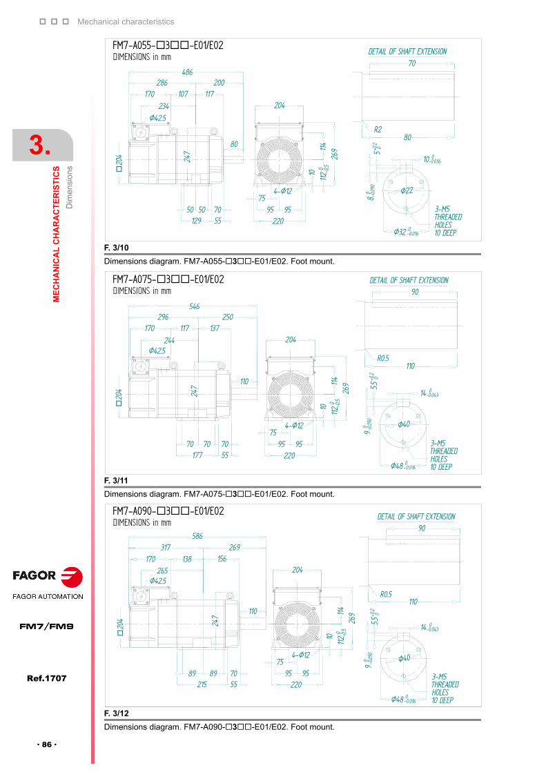
Mechanical characteristics
3.
ME
CH
AN
ICA
L C
HA
RA
CT
ER
IST
ICS
Dim
ensi
ons
116
Ref.1707
FM7/FM9
· 86 ·
F. 3/10
Dimensions diagram. FM7-A055-3-E01/E02. Foot mount.
F. 3/11
Dimensions diagram. FM7-A075-3-E01/E02. Foot mount.
F. 3/12
Dimensions diagram. FM7-A090-3-E01/E02. Foot mount.
80
70
R2
DETAIL OF SHAFT EXTENSION
Ø32 0 -0.016
3-M5THREADEDHOLES
Ø22
5+0.2 0
80 -0.09
0
10 0-0.036
Ø42.5
204
4-Ø12
22095 95
75
204
26911
411
20 -0.5
10
486286 200
129 5550 50 70
247
170 107 117234
80
DIMENSIONS in mmFM7-A055-3-E01/E02
110
90
R0.5
DETAIL OF SHAFT EXTENSION
Ø48 0 -0.016
3-M5THREADEDHOLES10 DEEP
Ø40
5.5+0
.2 09
0 -0.09
0
14 0-0.043
Ø42.5
4-Ø12
22095 95
75
20426
9114
1120 -0.5
1020
4 247
177 5570 70 70
244
170 117 137296 250
546
110
DIMENSIONS in mmFM7-A075-3-E01/E02
247
170 156138269317
586
110
215 5589 89 70
90
R0.5
DETAIL OF SHAFT EXTENSION
Ø48 0 -0.016
3-M5THREADEDHOLES10 DEEP
Ø40
5.5+0
.2 09
0 -0.09
0
14 0-0.043
4-Ø12
22095 95
75
204
269114
112
0 -0.5
10
Ø42.5
265
110
DIMENSIONS in mmFM7-A090-3-E01/E02

Mechanical characteristics
ME
CH
AN
ICA
L C
HA
RA
CT
ER
IST
ICS
Dim
ensi
ons
3.
Ref.1707
· 87 ·
FM7/FM9
F. 3/13
Dimensions diagram. FM7-A110-3-E01, FM7-A150-3-E01/E02. Foot mount.
F. 3/14
Dimensions diagram. FM7-A185-3-E01, FM7-B120-3-E01/E02. Foot mount.
F. 3/15
Dimensions diagram. FM7-A220-3-E01, FM7-B170-3-E01/E02. Foot mount.
110
90
R1
DETAIL OF SHAFT EXTENSION
Ø48 0 -0.016
3-M5THREADEDHOLES
Ø40
5.5+0
.2 09
0 -0.09
0
14 0-0.043
4-Ø15
26
0
16
341
131
160
0 -0.5
250
29089
110
191Ø42.5
176 19658307261
568
127 12755 55
331.5
223 8489 108
DIMENSIONS in mmFM7-A110-3-E01, FM7-A150-3-E01/E02
110
255 84105 108105
110
90
R1
DETAIL OF SHAFT EXTENSION
Ø48 0 -0.016
3-M5THREADEDHOLES10 DEEP
Ø40
5.5+0
.2 09
0 -0.09
0
14 0-0.043
4-Ø15
16
341
131
160
0 -0.5
323307630
26
0
Ø42.5
331.5
237176 212104
250
290127 127
55 55
DIMENSIONS in mmFM7-A185-3-E01/E02, FM7-B120-3-E01/E02
110
357.5310.5668
Ø42.5
324 84139.5 108139.5
331.5
26
0
240.5176 246.5107.5
90
R1
Ø48 0 -0.016
3-M5THREADEDHOLES10 DEEP
Ø40
5.5+0
.2 09
0 -0.09
0
14 0-0.043
4-Ø15
16
341
131
160
0 -0.5
250
290127 127
55 55
110
DIMENSIONS in mmFM7-A220-3-E01/E02, FM7-B170-3-E01/E02
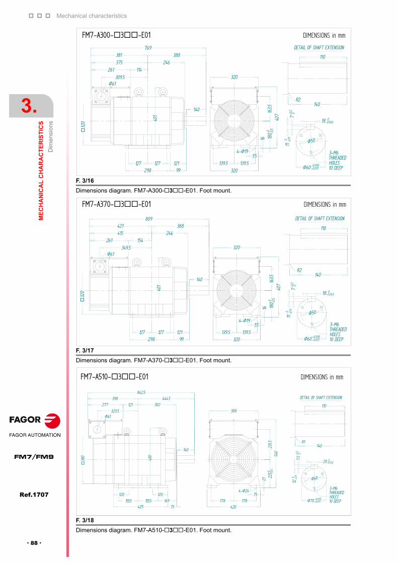
Mechanical characteristics
3.
ME
CH
AN
ICA
L C
HA
RA
CT
ER
IST
ICS
Dim
ensi
ons
116
Ref.1707
FM7/FM9
· 88 ·
F. 3/16
Dimensions diagram. FM7-A300-3-E01. Foot mount.
F. 3/17
Dimensions diagram. FM7-A370-3-E01. Foot mount.
F. 3/18
Dimensions diagram. FM7-A510-3-E01. Foot mount.
140
110
R2
DETAIL OF SHAFT EXTENSION
Ø60 +0.011
3-M6THREADEDHOLES10 DEEP
Ø50
7+0
.2 0
110 -0.11
18 0-0.043
+0.030
4-Ø1955
139.5 139.5
375 246381
140
388769
320
298
Ø61
320
16
407
163.5
180
0 -0.5
309.5261 114
401
99127 121127
DIMENSIONS in mmFM7-A300-3-E01
349.5261 154
415 246421 388
809
140140
110
R2
DETAIL OF SHAFT EXTENSION
Ø60 +0.011
3-M6THREADEDHOLES10 DEEP
Ø50
7+0
.2 0
110 -0.11
18 0-0.043
+0.030
4-Ø19
16
407
163.5
180
0 -0.5
55139.5 139.5
320
320
298 99127 121127
401
32
0
Ø61
DIMENSIONS in mmFM7-A370-3-E01
Ø61
480
140
+0.030
140
110
R1
DETAIL OF SHAFT EXTENSION
Ø70 +0.011
3-M6THREADEDHOLES10 DEEP
Ø60
7.5+0
.2 0
120 -0.11
20 0-0.052
388
4-Ø2475
178 178420
21
540
235.5
2250 -0
.5
120
323.5
38
0
277 121398
302
842.5
425 73155.5 149155.5
120
444.5
DIMENSIONS in mmFM7-A510-3-E01
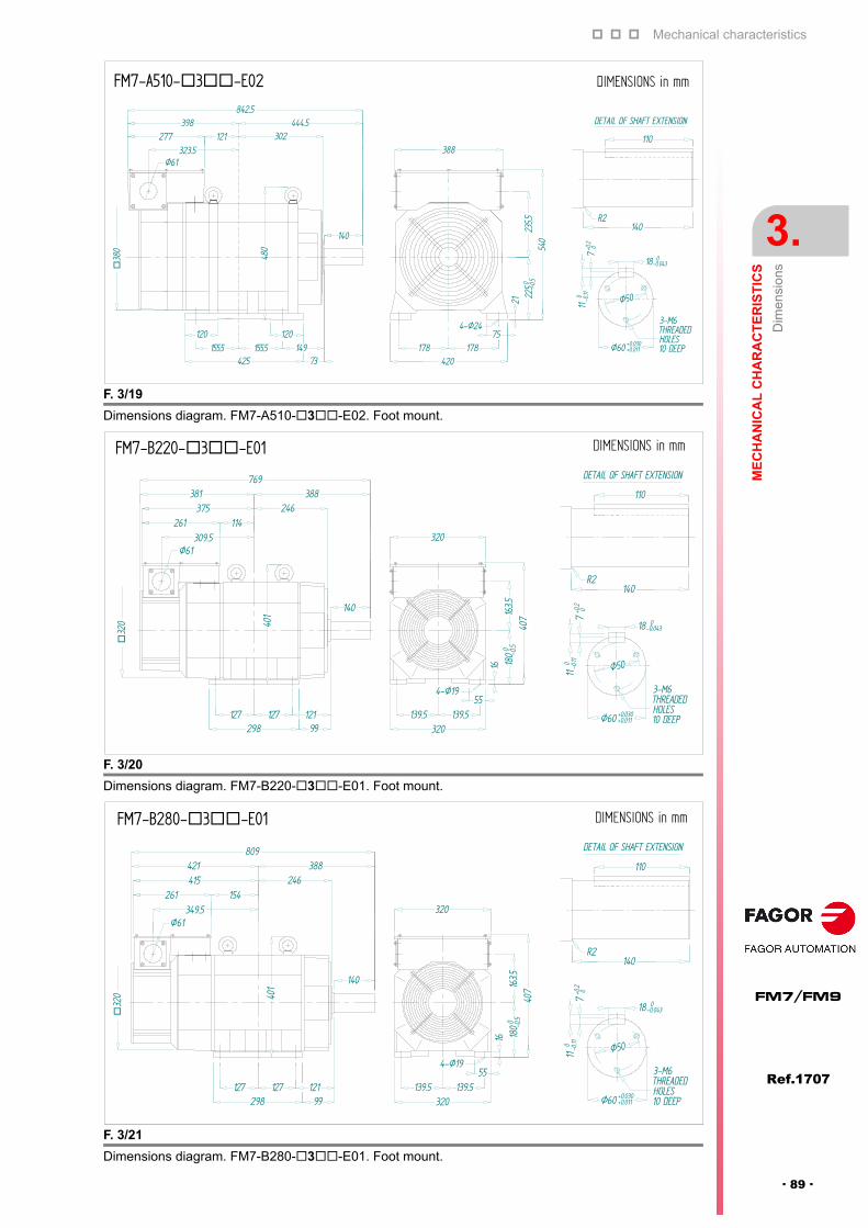
Mechanical characteristics
ME
CH
AN
ICA
L C
HA
RA
CT
ER
IST
ICS
Dim
ensi
ons
3.
Ref.1707
· 89 ·
FM7/FM9
F. 3/19
Dimensions diagram. FM7-A510-3-E02. Foot mount.
F. 3/20
Dimensions diagram. FM7-B220-3-E01. Foot mount.
F. 3/21
Dimensions diagram. FM7-B280-3-E01. Foot mount.
140
110
R2
DETAIL OF SHAFT EXTENSION
Ø60 +0.011
3-M6THREADEDHOLES10 DEEP
Ø50
7+0
.2 0
110 -0.11
18 0-0.043
+0.030155.5120
444.5
120
Ø61
480
140
4-Ø2475
178 178420
21
540
235.5
2250 -0
.5
388323.5
38
0
277 121398
302
842.5
425 73155.5 149
DIMENSIONS in mmFM7-A510-3-E02
127
261 114375
381246
388769
3-M6THREADEDHOLES10 DEEP
Ø50
7+0
.2 0
110 -0.11
18 0-0.043
+0.030
4-Ø19
401
Ø61
32
0
320309.5
140
55139.5
320139.5
16
40716
3.518
00 -0.5
298 99121127
140
110
R2
DETAIL OF SHAFT EXTENSION
Ø60 +0.011
DIMENSIONS in mmFM7-B220-3-E01
110
R2
DETAIL OF SHAFT EXTENSION
Ø60 +0.011
3-M6THREADEDHOLES10 DEEP
Ø50
7+0
.2 0
110 -0.11
18 0-0.043
+0.030
388809
401
140
298 99121127 127
Ø61349.5
261 154415 246421
140
4-Ø19
320
55139.5
320139.5
16
40716
3.518
00 -0.5
DIMENSIONS in mmFM7-B280-3-E01
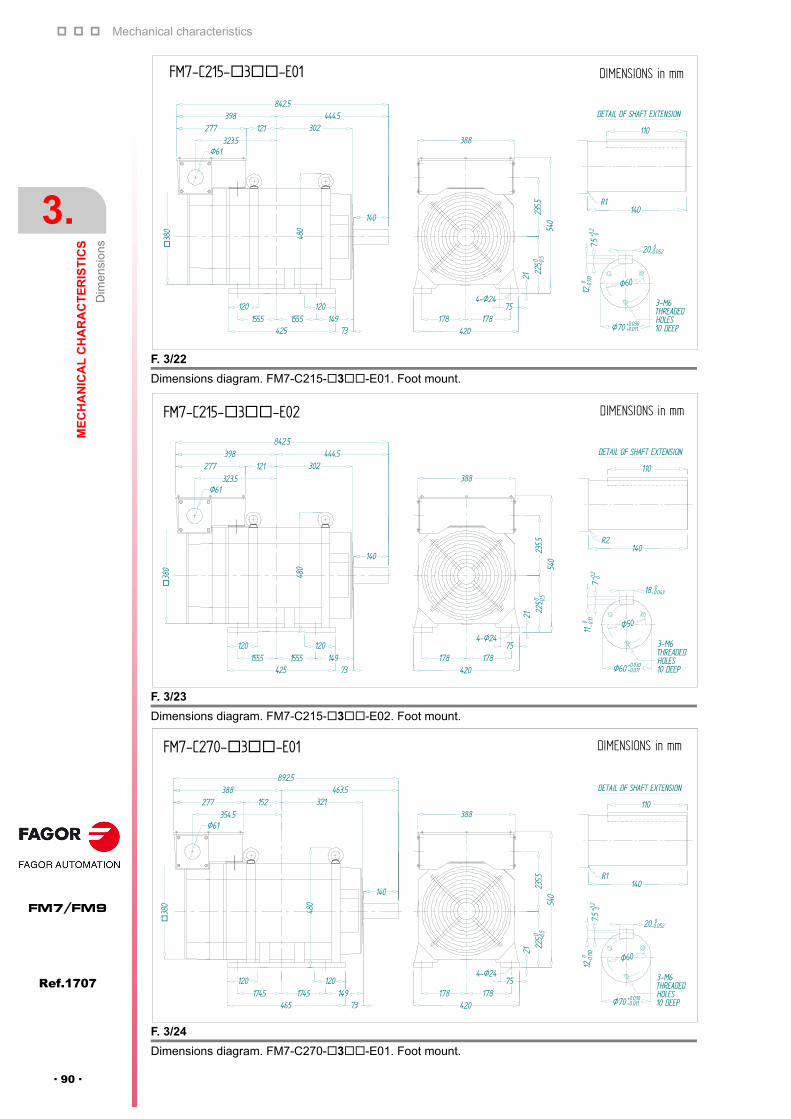
Mechanical characteristics
3.
ME
CH
AN
ICA
L C
HA
RA
CT
ER
IST
ICS
Dim
ensi
ons
116
Ref.1707
FM7/FM9
· 90 ·
F. 3/22
Dimensions diagram. FM7-C215-3-E01. Foot mount.
F. 3/23
Dimensions diagram. FM7-C215-3-E02. Foot mount.
F. 3/24
Dimensions diagram. FM7-C270-3-E01. Foot mount.
140
110
R1
DETAIL OF SHAFT EXTENSION
Ø70 +0.011
3-M6THREADEDHOLES10 DEEP
Ø60
7.5+0
.2 0
120
-0.11
0
20 0-0.052
+0.030
Ø61
480
140
4-Ø2475
178 178420
21
540
235.5
2250 -0
.5
388323.5
38
0
277 121398
302
842.5
425 73155.5 149155.5
120
444.5
120
DIMENSIONS in mmFM7-C215-3-E01
121398
302
842.5
425 73155.5 149155.5
120
444.5
120
Ø61
480
140
4-Ø2475
178 178420
21
540
235.5
2250 -0
.5
388323.5
38
0
277
140
110
R2
DETAIL OF SHAFT EXTENSION
Ø60 +0.011
3-M6THREADEDHOLES10 DEEP
Ø50
7+0
.2 0
110 -0.11
18 0-0.043
+0.030
DIMENSIONS in mmFM7-C215-3-E02
DIMENSIONS in mmFM7-C270-3-E01
465 73174.5 149
120120
480
Ø61354.5
277 152 321388 463.5
892.5
174.5
38
0
140
21
540
235.5
2250 -0
.5
388
4-Ø2475
178 178420
140
110
R1
DETAIL OF SHAFT EXTENSION
Ø70 +0.011
3-M6THREADEDHOLES10 DEEP
Ø60
7.5+0
.2 0
120
-0.11
0
20 0-0.052
+0.030

Mechanical characteristics
ME
CH
AN
ICA
L C
HA
RA
CT
ER
IST
ICS
Dim
ensi
ons
3.
Ref.1707
· 91 ·
FM7/FM9
F. 3/25
Dimensions diagram. FM7-C270-3-E02. Foot mount.
F. 3/26
Dimensions diagram. FM7-E600-3-E01. Foot mount.
DIMENSIONS in mmFM7-C270-3-E02
140
110
R2
DETAIL OF SHAFT EXTENSION
Ø60 +0.011
3-M6THREADEDHOLES10 DEEP
Ø50
7+0
.2 0
110
-0.11
0
18 0-0.043
+0.030
4-Ø2475
178 178420
21
540
235.5
2250 -0
.5
388277 152 321
388 463.5892.5
174.5
38
0
140
465 73174.5 149
120120
480
Ø61354.5
4x2-Ø24HOLES
Ø400
Ø45
0
37.5°
37.5°Ø65 +0.030
+0.011
3-M6THREADED HOLES10 DEEP
Ø55
7+0.2 0
110 -0.11
0
18 0-0.043
140
110
R1
DETAIL OF SHAFT EXTENSION
NOTES:1. ARROW INDICATES THE DIRECTION OF COOLING AIR2. OIL SEAL IS PROVIDED. OIL SHOULD BE SPLASHED TO OIL SEAL
388
ARROW A
370
1065.5
547.5 476.5
Ø61
38
0
277
540
21 225
0 -0.5
235.5
312 336.5 140851
514.5
480
140
A
Ø35
00 -0.05
7
22
420178 178
90 904-Ø24
5
120 120 65228.5 228.5
590
388
DIMENSIONS in mmFM7-E600-3-E01

Mechanical characteristics
3.
ME
CH
AN
ICA
L C
HA
RA
CT
ER
IST
ICS
Dim
ensi
ons
116
Ref.1707
FM7/FM9
· 92 ·
3.7.2 Assembling precision
3.7.3 FM7-XXXX-X1XX-E01/E02
T. 3/6 Assembling precision in mm. FM7--3-E01/E02 series. Foot mount.
Model Parallelism of the shaft extension
Runout of the shaft extension
FM7-A037-3-E01/E02 0.030 0.020
FM7-A055-3-E01/E02 0.030 0.020
FM7-A075-3-E01/E02 0.033 0.022
FM7-A090-3-E01/E02 0.033 0.022
FM7-A110-3-E01 0.033 0.022
FM7-A150-3-E01/E02 0.033 0.022
FM7-A185-3-E01/E02 0.033 0.022
FM7-A220-3-E01/E02 0.033 0.022
FM7-A300-3-E01 0.042 0.028
FM7-A370-3-E01 0.042 0.028
FM7-A510-3-E01/E02 0.042 0.028
FM7-B120-3-E01/E02 0.033 0.022
FM7-B170-3-E01/E02 0.033 0.022
FM7-B220-3-E01 0.042 0.028
FM7-B280-3-E01 0.042 0.028
FM7-C215-3-E01/E02 0.042 0.028
FM7-C270-3-E01/E02 0.042 0.028
FM7-E600-C3B-E01 0.042 0.028
F. 3/27
Dimensions diagram. FM7-A037-1-E01/E02. Flange mount.
F. 3/28
Dimensions diagram. FM7-A055-1-E01/E02. Flange mount.
150
110.5
4-Ø11Ø185
174 60
45
R1
DETAIL OF SHAFT EXTENSION
Ø28 -0.013
3-M4THREADEDHOLES10 DEEP
Ø22
4+0.2 0
70 -0.09
0
8 0-0.036
0
17
4
60 Ø15
0 -0.0
40
225 214
512Ø34
Ø220
174
399407 60499
DIMENSIONS in mmFM7-A037-1-E01/E02
80
70
R2
DETAIL OF SHAFT EXTENSION
Ø32 -0.016
3-M5THREADEDHOLES10 DEEP
Ø22
5+0.2 0
80 -0.09
0
10 0-0.036
0
20
4
Ø42.5
4-Ø15
Ø250
204
158
114
204
Ø215
516
80
170 227354
406 80486
270
Ø18
0 -0.0
40
DIMENSIONS in mm
FM7-A055-1-E01/E02
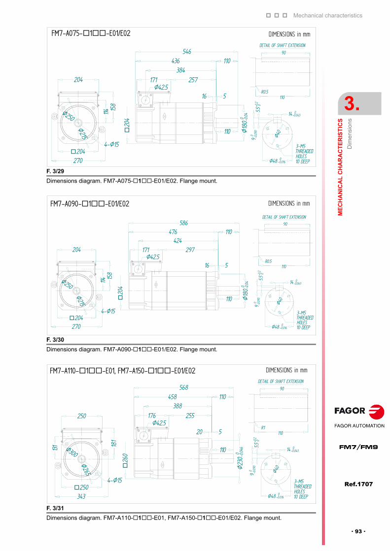
Mechanical characteristics
ME
CH
AN
ICA
L C
HA
RA
CT
ER
IST
ICS
Dim
ensi
ons
3.
Ref.1707
· 93 ·
FM7/FM9
F. 3/29
Dimensions diagram. FM7-A075-1-E01/E02. Flange mount.
F. 3/30
Dimensions diagram. FM7-A090-1-E01/E02. Flange mount.
F. 3/31
Dimensions diagram. FM7-A110-1-E01, FM7-A150-1-E01/E02. Flange mount.
110
90
R0.5
Ø48 -0.016
3-M5THREADEDHOLES10 DEEP
Ø40
5.5+0
.2 09
0 -0.09
0
14 0-0.043
0
20
4
Ø42.5
4-Ø15
Ø250
204
158
114
204
Ø215
516
110
171 257384
436 110546
270
Ø18
0 -0.0
40
DIMENSIONS in mmFM7-A075-1-E01/E02
DIMENSIONS in mmFM7-A090-1-E01/E02
20
4
Ø42.5110
90
R0.5
4-Ø15
Ø250
204
158
114
204Ø215
516
110
171 297424
476 110586
270
Ø18
0 -0.0
40
DETAIL OF SHAFT EXTENSION
Ø48 -0.016
3-M5THREADEDHOLES10 DEEP
Ø40
5.5+0
.2 09
0 -0.09
0
14 0-0.043
0
DIMENSIONS in mmFM7-A110-1-E01, FM7-A150-1-E01/E02
Ø265
343
255388
458 110568
Ø23
0 -0.0
460
110
90
R1
Ø48 -0.016
3-M5THREADEDHOLES10 DEEP
Ø40
5.5+0
.2 09
0 -0.09
0
4-Ø15
Ø300
250
181
131
250
14 0-0.043
0
26
0
Ø42.5520
110
176
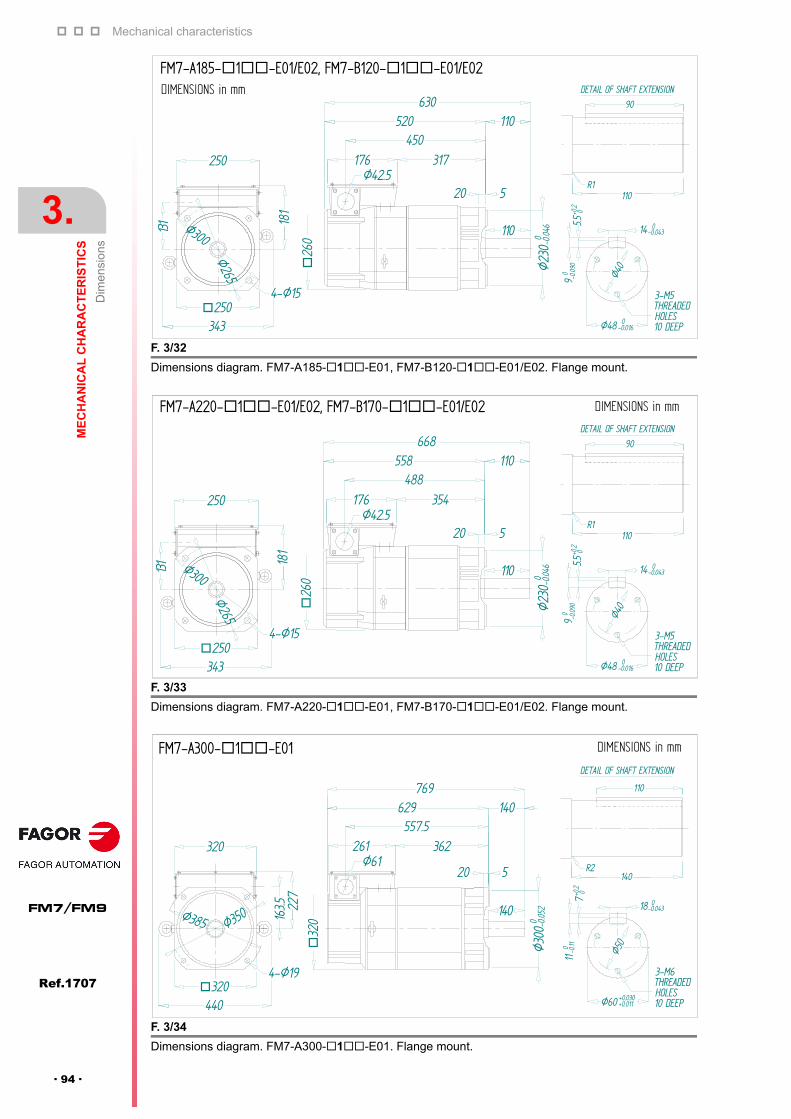
Mechanical characteristics
3.
ME
CH
AN
ICA
L C
HA
RA
CT
ER
IST
ICS
Dim
ensi
ons
116
Ref.1707
FM7/FM9
· 94 ·
F. 3/32
Dimensions diagram. FM7-A185-1-E01, FM7-B120-1-E01/E02. Flange mount.
F. 3/33
Dimensions diagram. FM7-A220-1-E01, FM7-B170-1-E01/E02. Flange mount.
F. 3/34
Dimensions diagram. FM7-A300-1-E01. Flange mount.
26
0
Ø42.5520
110
176 317450
520 110630
Ø23
0 -0.0
460
110
90
R1
DETAIL OF SHAFT EXTENSION
Ø48 -0.016
3-M5THREADEDHOLES10 DEEP
Ø40
5.5+0
.2 09
0 -0.09
0
14 0-0.043
0
4-Ø15
Ø300
250
181
250
Ø265
343
DIMENSIONS in mm
FM7-A185-1-E01/E02, FM7-B120-1-E01/E02
110
90
R1
DETAIL OF SHAFT EXTENSION
Ø48 -0.016
3-M5THREADEDHOLES10 DEEP
Ø40
5.5+0
.2 09
0 -0.09
014 0
-0.043
0
26
0
Ø42.5520
110
176 354488
558 110668
Ø23
0 -0.0
460
4-Ø15
Ø300
250
181
250
Ø265
343
DIMENSIONS in mmFM7-A220-1-E01/E02, FM7-B170-1-E01/E02
4-Ø19
Ø61
320440
Ø385 Ø350
320
163.5 22
7
261 362557.5
629 140769
520
140
Ø30
0 -0.0
520
140
110
R2
DETAIL OF SHAFT EXTENSION
Ø60 +0.011
3-M6THREADEDHOLES10 DEEP
Ø50
7+0.2 0
110 -0.11
18 0-0.043
+0.030
32
0
DIMENSIONS in mmFM7-A300-1-E01

Mechanical characteristics
ME
CH
AN
ICA
L C
HA
RA
CT
ER
IST
ICS
Dim
ensi
ons
3.
Ref.1707
· 95 ·
FM7/FM9
F. 3/35
Dimensions diagram. FM7-A370-1-E01. Flange mount.
F. 3/36
Dimensions diagram. FM7-A510-1-E01. Flange mount.
F. 3/37
Dimensions diagram. FM7-A510-1-E02. Flange mount.
DIMENSIONS in mmFM7-A370-1-E01
597.5669 140
809
520
140
Ø30
0 -0.0
520
140
110
R2
DETAIL OF SHAFT EXTENSION
Ø60 +0.011
3-M6THREADEDHOLES10 DEEP
Ø50
7+0.2 0
110 -0.11
18 0-0.043
+0.030
32
0
4-Ø19
Ø61
320
Ø385 Ø350
320
163.5 22
7
261 402
140
Ø61
38
0
277 430632.5
665.5
707 140847
522
140
Ø35
0 -0.0
570
110
R1
DETAIL OF SHAFT EXTENSION
Ø70 +0.011
3-M6THREADEDHOLES10 DEEP
Ø60
7.5+0
.2 0
120 -0.11
0
20 0-0.052
+0.030
388
235.5 31
5
4-Ø24370504
Ø450
Ø400
DIMENSIONS in mmFM7-A510-1-E01
140
110
R2
DETAIL OF SHAFT EXTENSION
Ø60 +0.011
3-M6THREADEDHOLES10 DEEP
Ø50
7+0
.2 0
110 -0.11
0
18 0-0.043
277 430632.5
665.5
707 140847
522
140
Ø35
0 -0.0
570
+0.030
388
235.5 31
5
4-Ø24370504
Ø450
Ø400
Ø61
38
0
DIMENSIONS in mmFM7-A510-1-E02

Mechanical characteristics
3.
ME
CH
AN
ICA
L C
HA
RA
CT
ER
IST
ICS
Dim
ensi
ons
116
Ref.1707
FM7/FM9
· 96 ·
F. 3/38
Dimensions diagram. FM7-B220-1-E01. Flange mount.
F. 3/39
Dimensions diagram. FM7-B280-1-E01. Flange mount.
F. 3/40
Dimensions diagram. FM7-C215-1-E01. Flange mount.
440
Ø385
Ø350
32
0
Ø61
Ø30
0 -0.0
520
140
320 261 362
163.5 22
7
520
557.5629 140769
140
110
R2
DETAIL OF SHAFT EXTENSION
Ø60 +0.011
3-M6THREADEDHOLES10 DEEP
Ø50
7+0
.2 0
110 -0.11
0
18 0-0.043
+0.030
4-Ø19320
DIMENSIONS in mmFM7-B220-1-E01
4-Ø19320440
Ø385
Ø350
32
0
Ø61Ø
300 -
0.052
0
140
320 261 402
163.5 22
7
140
110
R2
DETAIL OF SHAFT EXTENSION
Ø60 +0.011
3-M6THREADEDHOLES10 DEEP
Ø50
7+0
.2 0
110 -0.11
018 0
-0.043
+0.030
520
597.5669 140
809
DIMENSIONS in mmFM7-B280-1-E01
Ø61
38
0
Ø35
0 -0.0
570140
522
4-Ø24
235.5 315
370
277 430388 632.5
140
110
R1
DETAIL OF SHAFT EXTENSION
Ø70 +0.011
3-M6THREADEDHOLES10 DEEP
Ø60
7.5+0
.2 0
120 -0.11
0
20 0-0.052
+0.030
707 140847
Ø400
Ø450
DIMENSIONS in mmFM7-C215-1-E01

Mechanical characteristics
ME
CH
AN
ICA
L C
HA
RA
CT
ER
IST
ICS
Dim
ensi
ons
3.
Ref.1707
· 97 ·
FM7/FM9
F. 3/41
Dimensions diagram. FM7-C215-1-E02. Flange mount.
F. 3/42
Dimensions diagram. FM7-C270-1-E01. Flange mount.
F. 3/43
Dimensions diagram. FM7-C270-1-E02. Flange mount.
DIMENSIONS in mmFM7-C215-1-E02
Ø61
38
0
Ø35
0 -0.0
570140
522
4-Ø24
235.5 315
370
140
110
R2
DETAIL OF SHAFT EXTENSION
Ø60 +0.011
3-M6THREADEDHOLES10 DEEP
Ø50
7+0
.2 0
110 -0.11
0
18 0-0.043
+0.030
504
277 430388
665.5
632.5
707 140847
Ø400
Ø450
DIMENSIONS in mmFM7-C270-1-E01
Ø61
38
0
Ø35
0 -0.0
570140
522
4-Ø24
235.5 315
370504
277 480388
715.5
682.5
757 140897
Ø400
Ø450
140
110
R1
DETAIL OF SHAFT EXTENSION
Ø70 +0.011
3-M6THREADEDHOLES10 DEEP
Ø60
7.5+0
.2 0
120 -0.11
0
20 0-0.052
+0.030
DIMENSIONS in mmFM7-C270-1-E02
140897
Ø400
Ø450
140
110
R2
DETAIL OF SHAFT EXTENSION
Ø60 +0.011
3-M6THREADEDHOLES10 DEEP
Ø50
7+0
.2 0
110
-0.11
0
18 0-0.043
+0.030
Ø61
38
0
Ø35
0 -0.0
570140
522
4-Ø24
235.5 315
370504
277 480388
715.5
682.5
757

Mechanical characteristics
3.
ME
CH
AN
ICA
L C
HA
RA
CT
ER
IST
ICS
Dim
ensi
ons
116
Ref.1707
FM7/FM9
· 98 ·
3.7.4 Assembling precision
F. 3/44
Dimensions diagram. FM7-E600-1-E01. Flange mount.
T. 3/7 Assembling precision in mm. FM7--1-E01/E02 models. Flange mount.
Models Runout of the shaft extension
Concentricity of the fittingdiameter between the flangeand the shaft
Concentricity of the support face of the flange with respect to the machine axis
FM7-A037-1-E01/E02 0.020 0.040 0.040
FM7-A055-1-E01/E02 0.020 0.040 0.040
FM7-A075-1-E01/E02 0.022 0.040 0.040
FM7-A090-1-E01/E02 0.022 0.040 0.040
FM7-A110-1-E01/E02 0.022 0.046 0.040
FM7-A150-1-E01/E02 0.022 0.046 0.040
FM7-A185-1-E01/E02 0.022 0.046 0.040
FM7-A220-1-E01/E02 0.022 0.046 0.040
FM7-A300-1-E01 0.028 0.048 0.060
FM7-A370-1-E01 0.028 0.048 0.060
FM7-A510-1-E01/E02 0.028 0.070 0.072
FM7-B120-1-E01/E02 0.022 0.046 0.040
FM7-B170-1-E01/E02 0.022 0.046 0.040
FM7-B220-1-E01 0.028 0.048 0.060
FM7-B280-1-E01 0.028 0.048 0.060
FM7-C215-1-E01/E02 0.028 0.070 0.072
FM7-C270-1-E01/E02 0.028 0.070 0.072
FM7-E600-C1B-E01 0.028 0.070 0.072
526
315
235.5
851
884
648.5
925.5 140
140
Ø35
00 -0.05
7
22 5R1
4x2-Ø24HOLES
Ø400Ø
450
37.5°37
.5°Ø65 +0.030
+0.011
3-M6THREADEDHOLES10 DEEP
Ø55
7+0.2 0
1065.5
Ø61
38
0
277
110 -0.11
0
18 0-0.043
140
110
388
370
DIMENSIONS in mmFM7-E600-1-E01
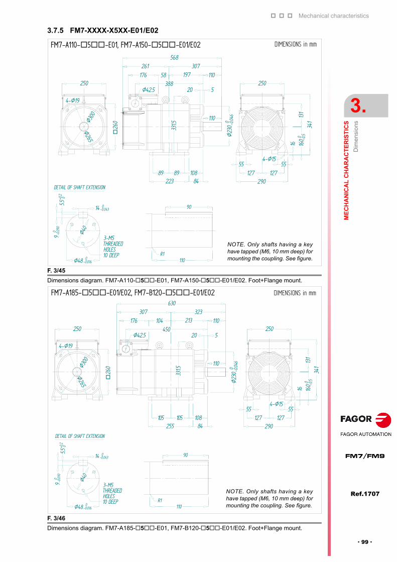
Mechanical characteristics
ME
CH
AN
ICA
L C
HA
RA
CT
ER
IST
ICS
Dim
ensi
ons
3.
Ref.1707
· 99 ·
FM7/FM9
3.7.5 FM7-XXXX-X5XX-E01/E02
F. 3/45
Dimensions diagram. FM7-A110-5-E01, FM7-A150-5-E01/E02. Foot+Flange mount.
F. 3/46
Dimensions diagram. FM7-A185-5-E01, FM7-B120-5-E01/E02. Foot+Flange mount.
DETAIL OF SHAFT EXTENSION
Ø48-0.016
3-M5THREADEDHOLES10 DEEP
Ø40
5.5+0
.2 0
90
-0.09
0
14 0-0.043
0
90
110R1
DIMENSIONS in mmFM7-A110-5-E01, FM7-A150-5-E01/E02
NOTE. Only shafts having a keyhave tapped (M6, 10 mm deep) formounting the coupling. See figure.
331.5
8489 10889
110
388Ø42.5
176 19758307261
568
250
4-Ø19
Ø300
Ø265 Ø23
0 -0.0
460
520
110
4-Ø15
16
341
131
160
0 -0.5
250
127 12755 55
26
0
DIMENSIONS in mmFM7-A185-5-E01/E02, FM7-B120-5-E01/E02
Ø300
Ø265 Ø23
0 -0.0
460
12755 55
110
26
0
250
4-Ø19
255 84105 108105
Ø42.5
331.5
450176
4-Ø15
16
341
131
160
0 -0.5
250
290127
213104323307
630
110
520
DETAIL OF SHAFT EXTENSION
Ø48-0.016
3-M5THREADEDHOLES10 DEEP
Ø40
5.5+0
.2 0
90
-0.09
0
14 0-0.043
0
90
110R1
NOTE. Only shafts having a keyhave tapped (M6, 10 mm deep) formounting the coupling. See figure.
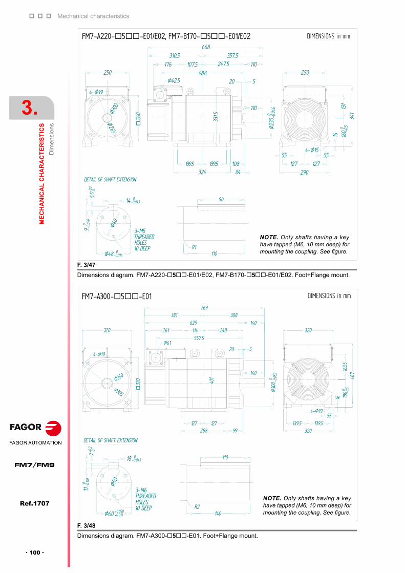
Mechanical characteristics
3.
ME
CH
AN
ICA
L C
HA
RA
CT
ER
IST
ICS
Dim
ensi
ons
116
Ref.1707
FM7/FM9
· 100 ·
F. 3/47
Dimensions diagram. FM7-A220-5-E01/E02, FM7-B170-5-E01/E02. Foot+Flange mount.
F. 3/48
Dimensions diagram. FM7-A300-5-E01. Foot+Flange mount.
DETAIL OF SHAFT EXTENSION
3-M5THREADEDHOLES10 DEEP
Ø40
5.5+0
.2 0
90
-0.09
0
14 0-0.043
0
90
110R1
250
4-Ø19
Ø300
Ø265
357.5310.5668
Ø23
0 -0.0
460
Ø42.5
324 84139.5 108139.5
331.5
26
0
488176 247.5107.5
110
4-Ø15
1613
116
00 -0.5
250
290127 127
55 55
520
110
DIMENSIONS in mmFM7-A220-5-E01/E02, FM7-B170-5-E01/E02
NOTE. Only shafts having a keyhave tapped (M6, 10 mm deep) formounting the coupling. See figure.
DETAIL OF SHAFT EXTENSION
Ø60 +0.011
3-M6THREADEDHOLES10 DEEP
Ø50
7+0.2 0
110 -0.11
0
18 0-0.043
+0.030
110
140R2
DIMENSIONS in mmFM7-A300-5-E01
4-Ø19
Ø6116
407
163.5
180
0 -0.5
557.5261 114
401
55139.5 139.5
629381
140
388769
320
298 99127127
520
Ø30
0 -0.0
520
248140
32
0
320
4-Ø19
Ø350
Ø385
NOTE. Only shafts having a keyhave tapped (M6, 10 mm deep) formounting the coupling. See figure.

Mechanical characteristics
ME
CH
AN
ICA
L C
HA
RA
CT
ER
IST
ICS
Dim
ensi
ons
3.
Ref.1707
· 101 ·
FM7/FM9
F. 3/49
Dimensions diagram. FM7-A370-5-E01. Foot+Flange mount.
F. 3/50
Dimensions diagram. FM7-A510-5-E01. Foot+Flange mount.
DIMENSIONS in mmFM7-A370-5-E01
520
Ø30
0 -0.0
520
298 99127127
401
Ø61597.5
261 154669
248
421809
140
140388
32
0
4-Ø19
16
407
163.5
180
0 -0.5
55139.5 139.5
320
320320
4-Ø19
Ø350
Ø385
R2
DETAIL OF SHAFT EXTENSION
Ø60 +0.011
3-M6THREADEDHOLES10 DEEP
Ø50
7+0.2 0
110 -0.11
0
18 0-0.043
+0.030
110
140
NOTE. Only shafts having a keyhave tapped (M6, 10 mm deep) formounting the coupling. See figure.
DETAIL OF SHAFT EXTENSION
Ø70 +0.011
3-M6THREADEDHOLES10 DEEP
Ø60
7.5+0
.2 0
120 -0.11
0
20 0-0.043
+0.030
110
140R1
DIMENSIONS in mmFM7-A510-5-E01
38
0
277 121398
449
707
425 77155.5155.5
120
309
120
847140
Ø61
480
140
4-Ø2475
178 178420
21
540
235.5
2250 -0
.5
388632.5
522
Ø35
0 -0.0
570
388
370
Ø400
Ø45
0
4-Ø24
NOTE. Only shafts having a keyhave tapped (M6, 10 mm deep) formounting the coupling. See figure.

Mechanical characteristics
3.
ME
CH
AN
ICA
L C
HA
RA
CT
ER
IST
ICS
Dim
ensi
ons
116
Ref.1707
FM7/FM9
· 102 ·
F. 3/51
Dimensions diagram. FM7-A510-5-E02. Foot+Flange mount.
F. 3/52
Dimensions diagram. FM7-B220-5-E01. Foot+Flange mount.
DIMENSIONS in mmFM7-A510-5-E02
38
0
277 121398
449
707
425 77155.5155.5
120
309
120
847140
Ø61
480
140
4-Ø2475
178 178420
21
540
235.5
2250 -0
.5
388632.5
522
Ø35
0 -0.0
570
388
370
Ø400Ø
450
4-Ø24
Ø60 +0.011
3-M6THREADEDHOLES10 DEEP
Ø50
7+0.2 0
110 -0.11
0
18 0-0.043
+0.030
110
140R2
DETAIL OF SHAFT EXTENSION
NOTE. Only shafts having a keyhave tapped (M6, 10 mm deep) formounting the coupling. See figure.
Ø30
0 -0.0
520
520
140
32
0
320
4-Ø19
Ø350
Ø385
401
Ø61557.5
140
298 99127 127
261 114629
381
248
388
4-Ø19
320
55139.5
320139.5
16
40716
3.518
00 -0.5
DIMENSIONS in mmFM7-B220-5-E01
DETAIL OF SHAFT EXTENSION
Ø60 +0.011
3-M6THREADEDHOLES10 DEEP
Ø50
7+0
.2 0
110 -0.11
0
18 0-0.043
+0.030
110
140R2
NOTE. Only shafts having a keyhave tapped (M6, 10 mm deep) formounting the coupling. See figure.
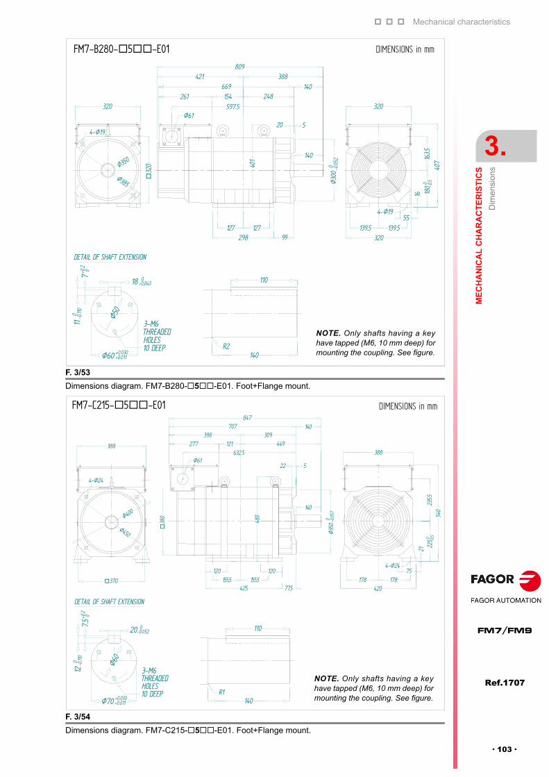
Mechanical characteristics
ME
CH
AN
ICA
L C
HA
RA
CT
ER
IST
ICS
Dim
ensi
ons
3.
Ref.1707
· 103 ·
FM7/FM9
F. 3/53
Dimensions diagram. FM7-B280-5-E01. Foot+Flange mount.
F. 3/54
Dimensions diagram. FM7-C215-5-E01. Foot+Flange mount.
DETAIL OF SHAFT EXTENSION
Ø60 +0.011
3-M6THREADEDHOLES10 DEEP
Ø50
7+0.2 0
110 -0.11
0
18 0-0.043
+0.030
110
140R2
DIMENSIONS in mmFM7-B280-5-E01
127
Ø61597.5
261 154669
421 388809
32
0 401
140
298 99127
4-Ø19
320
55139.5
320139.5
16
40716
3.518
00 -0.5Ø30
0 -0.0
520
520
248140
320
4-Ø19
Ø350
Ø385
NOTE. Only shafts having a keyhave tapped (M6, 10 mm deep) formounting the coupling. See figure.
DETAIL OF SHAFT EXTENSION
Ø70 +0.011
3-M6THREADEDHOLES10 DEEP
Ø60
7.5+0
.2 0
120 -0.11
0
20 0-0.052
+0.030
110
140R1
DIMENSIONS in mmFM7-C215-5-E01
4-Ø2475
178 178420
21
540
235.5
2250 -0
.5
388Ø61
480
632.5
38
0
277 121398
449
707
425 77.5155.5155.5
120
309
120
Ø35
0 -0.0
570
140
522
140
4-Ø24
370
388
Ø400
Ø450
847
NOTE. Only shafts having a keyhave tapped (M6, 10 mm deep) formounting the coupling. See figure.

Mechanical characteristics
3.
ME
CH
AN
ICA
L C
HA
RA
CT
ER
IST
ICS
Dim
ensi
ons
116
Ref.1707
FM7/FM9
· 104 ·
F. 3/55
Dimensions diagram. FM7-C215-5-E02. Foot+Flange mount.
F. 3/56
Dimensions diagram. FM7-C270-5-E01. Foot+Flange mount.
DETAIL OF SHAFT EXTENSION
Ø60 +0.011
3-M6THREADEDHOLES10 DEEP
Ø60
7+0.2 0
110 -0.11
0
18 0-0.043
+0.030
110
140R2
DIMENSIONS in mmFM7-C215-5-E02
4-Ø2475
178 178420
21
540
235.5
2250 -0
.5
388Ø61
480
632.5
38
0
277 121398
449
707
425 77.5155.5155.5
120
309
120
Ø35
0 -0.0
570
140
522
140
4-Ø24
370
388
Ø400
Ø450
847
NOTE. Only shafts having a keyhave tapped (M6, 10 mm deep) formounting the coupling. See figure.
DIMENSIONS in mmFM7-C270-5-E01
DETAIL OF SHAFT EXTENSION
Ø70 +0.011
3-M6THREADEDHOLES10 DEEP
Ø60
7.5+0
.2 0
120 -0.11
0
20 0-0.052
+0.030
110
140R1
328
149
Ø400
Ø450 Ø35
0 -0.0
570
140
522
140897
4-Ø24
370
388
Ø61
480
682.5
38
0
277 152757
465 73174.5174.5
120120
21
540
235.5
2250 -0
.5
388
4-Ø2475
178 178420
NOTE. Only shafts having a keyhave tapped (M6, 10 mm deep) formounting the coupling. See figure.

Mechanical characteristics
ME
CH
AN
ICA
L C
HA
RA
CT
ER
IST
ICS
Dim
ensi
ons
3.
Ref.1707
· 105 ·
FM7/FM9
F. 3/57
Dimensions diagram. FM7-C270-5-E02. Foot+Flange mount.
F. 3/58
Dimensions diagram. FM7-E600-5-E01. Foot+Flange mount.
DIMENSIONS in mmFM7-C270-5-E02
DETAIL OF SHAFT EXTENSION
Ø70 +0.011
3-M6THREADEDHOLES10 DEEP
Ø60
7.5+0
.2 0
120 -0.11
0
20 0-0.052
+0.030
110
140R1
328
149
Ø400
Ø450 Ø35
0 -0.0
570
140
522
140897
4-Ø24
370
388
Ø61
480
682.5
38
0
277 152757
465 73174.5174.5
120120
21
540
235.5
2250 -0
.5
388
4-Ø2475
178 178420
NOTE. Only shafts having a keyhave tapped (M6, 10 mm deep) formounting the coupling. See figure.
1065.5
547.5 476.5
Ø61
38
0
277 312 336.5 140851
514.5
480
140
Ø35
00 -0.05
7
22 5
120 120 65228.5 228.5
590
388
420178 178
90 904-Ø24
540
21 225
0 -0.5
235.5
4x2-Ø24HOLES
Ø400
Ø45
0
37.5°
37.5°
388
370
DIMENSIONS in mmFM7-E600-5-E01
Ø65 +0.011
3-M6THREADEDHOLES10 DEEP
Ø55
7+0
.2 0
110 -0.11
0
18 0-0.043
+0.030
110
140R1
NOTE. Only shafts having a keyhave tapped (M6, 10 mm deep) formounting the coupling. See figure.
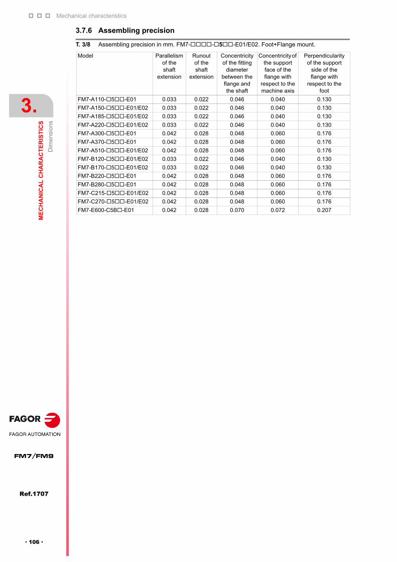
Mechanical characteristics
3.
ME
CH
AN
ICA
L C
HA
RA
CT
ER
IST
ICS
Dim
ensi
ons
116
Ref.1707
FM7/FM9
· 106 ·
3.7.6 Assembling precision
T. 3/8 Assembling precision in mm. FM7--5-E01/E02. Foot+Flange mount.
Model Parallelism of the shaft
extension
Runout of the shaft
extension
Concentricity of the fitting
diameter between the flange and the shaft
Concentricity of the support face of the flange with
respect to the machine axis
Perpendicularity of the support
side of the flange with
respect to the foot
FM7-A110-5-E01 0.033 0.022 0.046 0.040 0.130
FM7-A150-5-E01/E02 0.033 0.022 0.046 0.040 0.130
FM7-A185-5-E01/E02 0.033 0.022 0.046 0.040 0.130
FM7-A220-5-E01/E02 0.033 0.022 0.046 0.040 0.130
FM7-A300-5-E01 0.042 0.028 0.048 0.060 0.176
FM7-A370-5-E01 0.042 0.028 0.048 0.060 0.176
FM7-A510-5-E01/E02 0.042 0.028 0.048 0.060 0.176
FM7-B120-5-E01/E02 0.033 0.022 0.046 0.040 0.130
FM7-B170-5-E01/E02 0.033 0.022 0.046 0.040 0.130
FM7-B220-5-E01 0.042 0.028 0.048 0.060 0.176
FM7-B280-5-E01 0.042 0.028 0.048 0.060 0.176
FM7-C215-5-E01/E02 0.042 0.028 0.048 0.060 0.176
FM7-C270-5-E01/E02 0.042 0.028 0.048 0.060 0.176
FM7-E600-C5B-E01 0.042 0.028 0.070 0.072 0.207
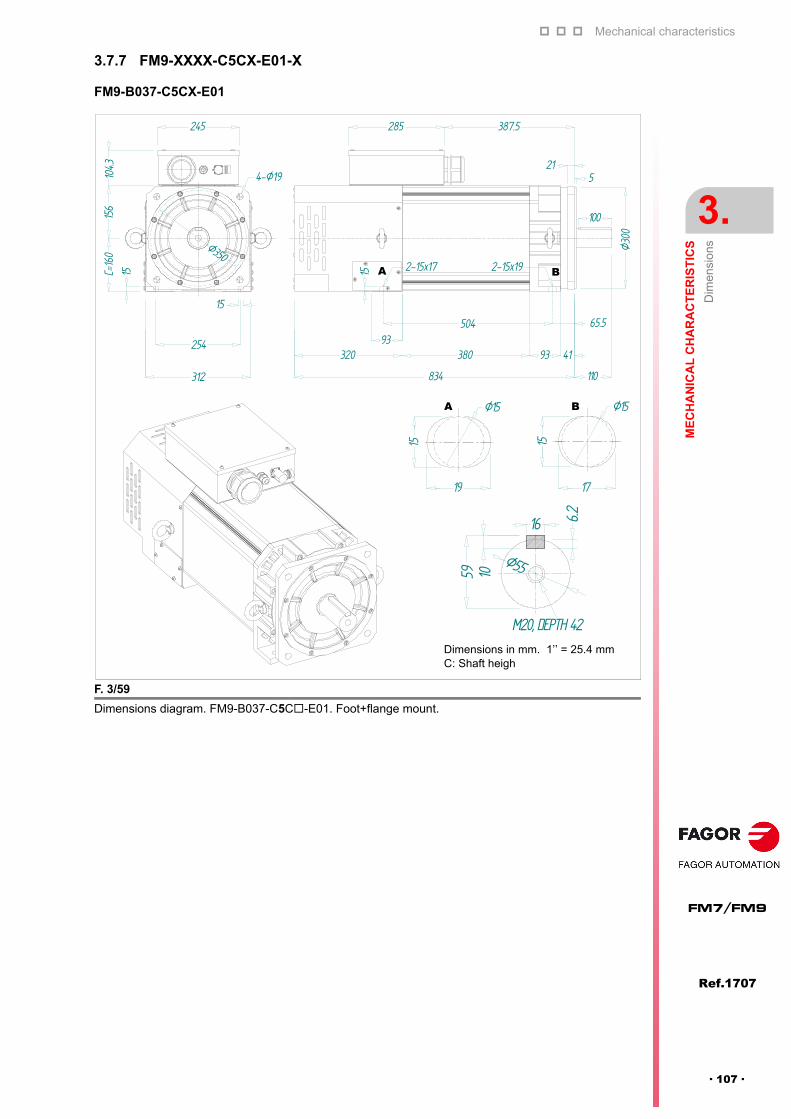
Mechanical characteristics
ME
CH
AN
ICA
L C
HA
RA
CT
ER
IST
ICS
Dim
ensi
ons
3.
Ref.1707
· 107 ·
FM7/FM9
3.7.7 FM9-XXXX-C5CX-E01-X
FM9-B037-C5CX-E01
F. 3/59
Dimensions diagram. FM9-B037-C5C-E01. Foot+flange mount.
M20, DEPTH 42
10
16 6.2Ø55
4-Ø19
Ø350
834 110
380320
100
245 285 387.5
521
Ø30
0
93 41
312
254
15
65.593
504
104.3
15 15 2-15x17 2-15x19
Ø15
15
Ø15
A B
BA
Dimensions in mm. 1’’ = 25.4 mm C: Shaft heigh
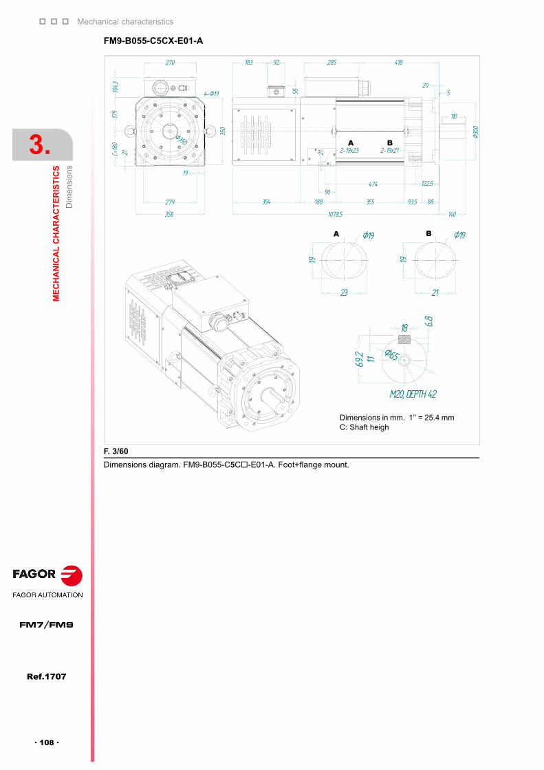
Mechanical characteristics
3.
ME
CH
AN
ICA
L C
HA
RA
CT
ER
IST
ICS
Dim
ensi
ons
116
Ref.1707
FM7/FM9
· 108 ·
FM9-B055-C5CX-E01-A
F. 3/60
Dimensions diagram. FM9-B055-C5C-E01-A. Foot+flange mount.
11
18 6.8
Ø65
Ø30
0
270
C=18
017
9
21
4-Ø19
350
279
19
358
Ø350
1078.5 140
188354 93.5 88355
122.590
474
183 92 285 418
520
58
2-19x2321 2-19x21
104.3
110
Dimensions in mm. 1’’ = 25.4 mm C: Shaft heigh
Ø19
19
Ø19A B
A B

Mechanical characteristics
ME
CH
AN
ICA
L C
HA
RA
CT
ER
IST
ICS
Dim
ensi
ons
3.
Ref.1707
· 109 ·
FM7/FM9
FM9-B071-C5CX-E01
F. 3/61
Dimensions diagram. FM9-B071-C5C-E01. Foot+Flange mount.
12
20 7.4
Ø75
308
454
8-Ø19
Ø500Ø550
265
165.3
C=22
5297 498
Ø45
0
130
525
443
356
8518.5
375
1259
1119 140
149222.5222.5
315
Ø18.5Ø18.5
Dimensions in mm. 1’’ = 25.4 mm C: Shaft heigh
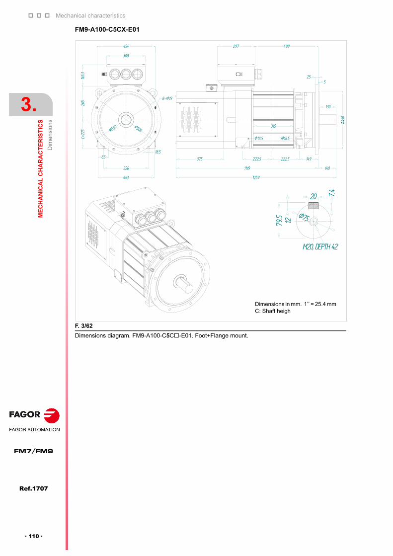
Mechanical characteristics
3.
ME
CH
AN
ICA
L C
HA
RA
CT
ER
IST
ICS
Dim
ensi
ons
116
Ref.1707
FM7/FM9
· 110 ·
FM9-A100-C5CX-E01
F. 3/62
Dimensions diagram. FM9-A100-C5C-E01. Foot+Flange mount.
12
20 7.4
Ø75
Ø45
0
130
375
1259
1119 140
149
Ø18.5
222.5
Ø18.5
308
454
8-Ø19
Ø500Ø550
265
165.3
C=22
5
443
356
8518.5
297 498
525
315
222.5
Dimensions in mm. 1’’ = 25.4 mm C: Shaft heigh

Mechanical characteristics
ME
CH
AN
ICA
L C
HA
RA
CT
ER
IST
ICS
Dim
ensi
ons
3.
Ref.1707
· 111 ·
FM7/FM9
FM9-B113-C5CX-E01
F. 3/63
Dimensions diagram. FM9-B113-C5C-E01. Foot+Flange mount.
12
20 7.4
Ø75
308
454
8-Ø19
Ø500Ø550
265
165.3
C=22
5
443
356
8518.5
297 683
Ø45
0
130
525
375
1444
1304 140
315 315
500
Ø18.5Ø18.5
149
Dimensions in mm. 1’’ = 25.4 mm C: Shaft heigh

Mechanical characteristics
3.
ME
CH
AN
ICA
L C
HA
RA
CT
ER
IST
ICS
Dim
ensi
ons
116
Ref.1707
FM7/FM9
· 112 ·
FM9-A130-C5CX-E01
F. 3/64
Dimensions diagram. FM9-A130-C5C-E01. Foot+Flange mount.Ø
450
130
375
1354
1214 140
270 149
Ø18.5
270
Ø18.5
308
454
8-Ø19
Ø500Ø550
265
165.3
C=22
5
443
356
8518.5
297 593
525
410
Dimensions in mm. 1’’ = 25.4 mm C: Shaft heigh
12
20 7.4
Ø75
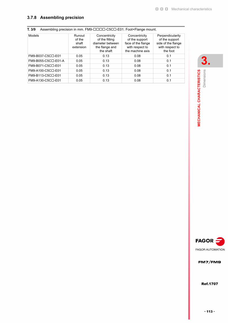
Mechanical characteristics
ME
CH
AN
ICA
L C
HA
RA
CT
ER
IST
ICS
Dim
ensi
ons
3.
Ref.1707
· 113 ·
FM7/FM9
3.7.8 Assembling precision
T. 3/9 Assembling precision in mm. FM9--C5C-E01. Foot+Flange mount.
Models Runout of the shaft
extension
Concentricity of the fitting
diameter between the flange and
the shaft
Concentricity of the support
face of the flange with respect to
the machine axis
Perpendicularity of the support
side of the flange with respect to
the foot
FM9-B037-C5C-E01 0.05 0.13 0.08 0.1
FM9-B055-C5C-E01-A 0.05 0.13 0.08 0.1
FM9-B071-C5C-E01 0.05 0.13 0.08 0.1
FM9-A100-C5C-E01 0.05 0.13 0.08 0.1
FM9-B113-C5C-E01 0.05 0.13 0.08 0.1
FM9-A130-C5C-E01 0.05 0.13 0.08 0.1

Mechanical characteristics
3.
ME
CH
AN
ICA
L C
HA
RA
CT
ER
IST
ICS
Dim
ensi
ons
116
Ref.1707
FM7/FM9
· 114 ·
3.7.9 FM7-DXXX-S1D0-E03
3.7.10 Assembling precision
F. 3/65
Dimensions diagram. FM7-D-S1D0-E03. Flange mount.
T. 3/10 Motor dimensions in mm. FM7-D-S1D0-E03. Flange mount.
Models L LA LB LC LG LH LL LR LD LE LF
FM7-D055-S1D0-E03 475 215 180 h7 204 20 250 415 60 353 226 171
FM7-D075-S1D0-E03 506 215 180 h7 204 20 250 446 60 401 256 190
FM7-D110-S1D0-E03 556 265 230 h7 250 25 300 476 80 420 271 205
FM7-D150-S1D0-E03 556 265 230 h7 250 25 300 476 80 420 271 205
FM7-D185-S1D0-E03 618 265 230 h7 250 25 300 538 80 482 333 205
FM7-D220-S1D0-E03 656 265 230 h7 250 25 300 576 80 520 371 205
T. 3/11 Motor and shaft dimensions in mm. FM7-D-S1D0-E03. Flange mount.
Models Z D I KD KL KI KE Q QR S
FM7-D055-S1D0-E03 15 204 270 42.5 158 204 114 60 0.5 28 h6
FM7-D075-S1D0-E03 15 204 270 42.5 164 250 114 60 0.5 28 h6
FM7-D110-S1D0-E03 15 260 343 42.5 183 279 131 80 0.5 38 h6
FM7-D150-S1D0-E03 15 260 343 42.5 183 279 131 80 0.5 38 h6
FM7-D185-S1D0-E03 15 260 343 42.5 183 279 131 80 0.5 38 h6
FM7-D220-S1D0-E03 15 260 343 42.5 183 279 131 80 0.5 38 h6
T. 3/12 Assembling precision in mm. FM7-D-S1D0-E03. Flange mount.
Models Runout of the shaft
extension
Concentricity of the fitting diameter between the flange
and the shaft
Concentricity of the support face of
the flange with respect to the machine axis
FM7-D055-S1D0-E03 0.020 0.040 0.04
FM7-D075-S1D0-E03 0.022 0.040 0.04
FM7-D110-S1D0-E03 0.022 0.046 0.04
FM7-D150-S1D0-E03 0.022 0.046 0.04
FM7-D185-S1D0-E03 0.022 0.046 0.04
FM7-D220-S1D0-E03 0.022 0.046 0.04
4-ØZLH
LA
Diameter ofmounting hole
KI
LC
I
L
LL
LD
LF LE
Q
LR
LB
LG5
KD
D
KL
KE
S Q
QRR
Symbol indicating the direction of the cooling air
Detail of the shaft extension
NOTE. This series does not allow the keyed shaftoption and, therefore, will not have tapped holes onthe shaft for mounting the coupling. See figure.

Mechanical characteristics
ME
CH
AN
ICA
L C
HA
RA
CT
ER
IST
ICS
Dim
ensi
ons
3.
Ref.1707
· 115 ·
FM7/FM9
3.7.11 FM7-DXXX-S1D0-HS3
F. 3/66
Dimensions diagram. FM7-D-S1D0-HS3. Flange mount.
T. 3/13 Motor dimensions in mm. FM7-D-S1D0-HS3. Flange mount.
FM7-D-S1D0-HS3
Model L LA LB LC LG LH LL LR LD LE LF
FM7-D075-S1D0-HS3 715 215 180 h7 204 20 250 446 60 401 256 190
FM7-D110-S1D0-HS3 751 265 230 h7 250 25 300 476 70 420 271 205
FM7-D185-S1D0-HS3 813 265 230 h7 250 25 300 538 70 482 333 205
FM7-D220-S1D0-HS3 851 265 230 h7 250 25 300 576 70 520 371 205
T. 3/14 Motor dimensions in mm. FM7-D-S1D0-HS3. Flange mount.
FM7-D-S1D0-HS3
Model Z D I KD KL KI KE L1 L2 L3
FM7-D075-S1D0-HS3 15 204 271 42.5 158 250 114 137 210 308
FM7-D110-S1D0-HS3 15 260 343 42.5 183 279 131 142 208 331
FM7-D185-S1D0-HS3 15 260 343 42.5 183 279 131 142 208 393
FM7-D220-S1D0-HS3 15 260 343 42.5 183 279 131 142 208 431
S
Ø6
QR0.5
dx 30°
mxl
X1
X2
X3
X4
RHRight-handscrew
KL
KE
LA
LH
I
LC
4-ØZDiameterof mounting
LL
LT LL LR
LF LE
LD
LG
5
Q
LB
I1
L1 L2 L3
I2
hole
KI
Ø18 ± 0.003
Ø45
Ø65
Ø100
Ø120
20
Ø19
xxxxxxxx
xx
M16x1.5LH
A
A
Apr
ox.2
A
A
7.5
11.
5
0.5
247.
5
30°
Left-hand screw
Terminal box center
4-M5
11 deep45°
90°
Ø90
threaded holes
air inletDirection of sealing
indicates the direction of the cooling airWith sealDirect coupling onlyUse the clean air through the air drier and filter fir sealing airAir pressure: 1 kg/cm²
· Detail of the shaft at the load end ·· Detail of the shaft at the end opposite to the load ·
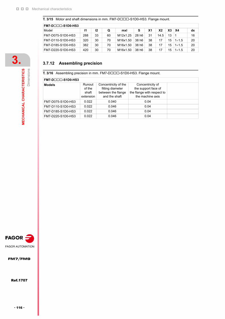
Mechanical characteristics
3.
ME
CH
AN
ICA
L C
HA
RA
CT
ER
IST
ICS
Dim
ensi
ons
116
Ref.1707
FM7/FM9
· 116 ·
3.7.12 Assembling precision
T. 3/15 Motor and shaft dimensions in mm. FM7-D-S1D0-HS3. Flange mount.
FM7-D-S1D0-HS3
Model I1 I2 Q mxl S X1 X2 X3 X4 dx
FM7-D075-S1D0-HS3 288 33 60 M12x1.25 28 h6 31 14.5 13 1 16
FM7-D110-S1D0-HS3 320 30 70 M16x1.50 38 h6 38 17 15 11.5 20
FM7-D185-S1D0-HS3 382 30 70 M16x1.50 38 h6 38 17 15 11.5 20
FM7-D220-S1D0-HS3 420 30 70 M16x1.50 38 h6 38 17 15 11.5 20
T. 3/16 Assembling precision in mm. FM7-D-S1D0-HS3. Flange mount.
FM7-D-S1D0-HS3
Models Runout of the shaft
extension
Concentricity of the fitting diameter
between the flange and the shaft
Concentricity of the support face of
the flange with respect to the machine axis
FM7-D075-S1D0-HS3 0.022 0.040 0.04
FM7-D110-S1D0-HS3 0.022 0.046 0.04
FM7-D185-S1D0-HS3 0.022 0.046 0.04
FM7-D220-S1D0-HS3 0.022 0.046 0.04

4
Ref.1707
· 117 ·
FM7/FM9
INSTALLATION
4.1 Overview
4.1.1 Motor installation
Before installing the motor, read the recommendations regarding itsinstallation environment and install it according to them.
Leave enough room around the motor for the air to be collected by thecooling fan integrated into the motor.
Keep a minimum gap of 100 mm (3.94 inches) between the machine andmotor cooling output.
Install it in a clean place, away from areas with oil and water. If there isa chance for the motor to be in contact with these elements, protect it withsome type of cover.
Make sure that the motor is firmly mounted either by feet or by flangebecause the weight of the motor or that of the dynamic load attached to itsshaft can generate vibrations when it is running.
Install it in a place free from dust and metal particles. The motor has anintegrated fan with an internal structure that supplies cooling air to themotor.
Clean the flange, the shaft and the keyway (if it has one) before installingthe motor.
Flange-mounted FM7 motor models may be installed with their shaft at theload end forming an angle between the horizontal and the vertical alwayswith their shaft facing down.
Foot-mounted FM7 motors must be installed with their feet secured tothe floor. When mounting the motor vertically, its shaft must always befacing down.
WARNING. If water or dirty oil gets inside the motor, its insulation resistancemay decrease causing a ground fault.
WARNING. Blocking the air flow with dust particles or other strange elementscan lower the efficiency of the cooling system.
INFORMATION. The flange and the motor's rotor shaft contain a layer ofanticorrosive paint or grease.i
DANGER. The motor cannot be installed with its shaft facing up on FM7motors.
DANGER. The motor cannot be installed with its shaft facing up on FM7motors.
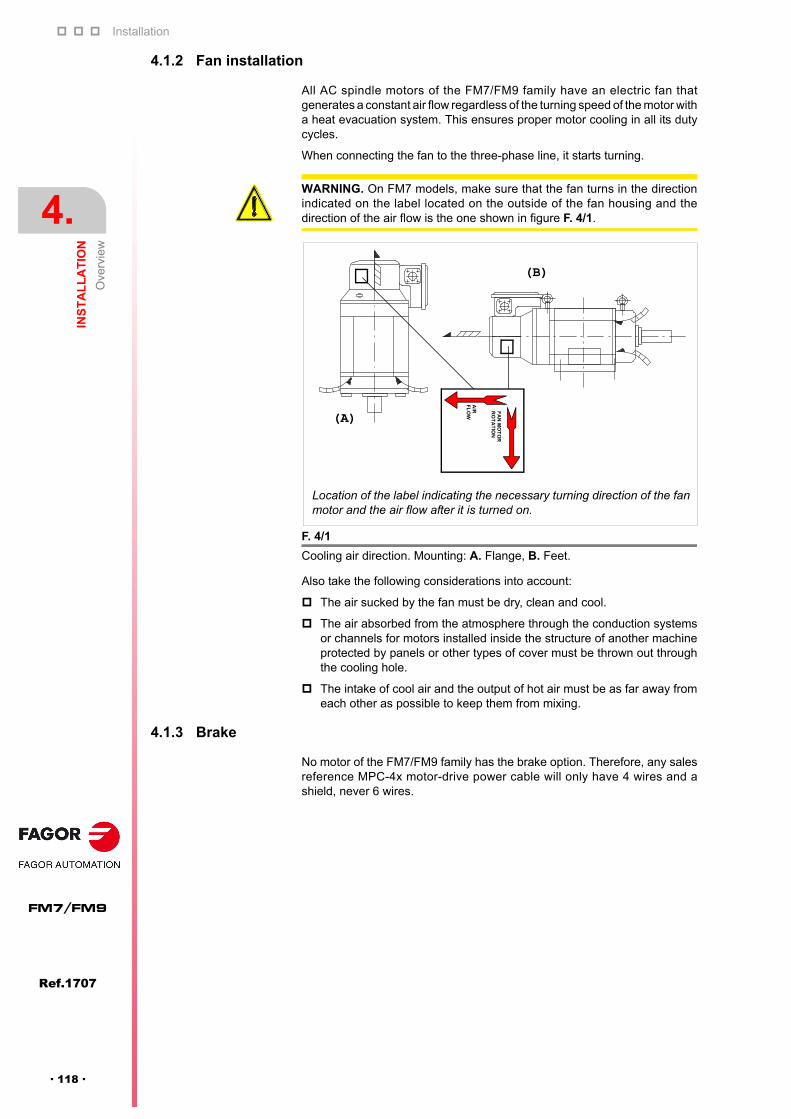
Installation
4.
INS
TA
LL
AT
ION
Ove
rvie
w
146
Ref.1707
FM7/FM9
· 118 ·
4.1.2 Fan installation
All AC spindle motors of the FM7/FM9 family have an electric fan thatgenerates a constant air flow regardless of the turning speed of the motor witha heat evacuation system. This ensures proper motor cooling in all its dutycycles.
When connecting the fan to the three-phase line, it starts turning.
Also take the following considerations into account:
The air sucked by the fan must be dry, clean and cool.
The air absorbed from the atmosphere through the conduction systemsor channels for motors installed inside the structure of another machineprotected by panels or other types of cover must be thrown out throughthe cooling hole.
The intake of cool air and the output of hot air must be as far away fromeach other as possible to keep them from mixing.
4.1.3 Brake
No motor of the FM7/FM9 family has the brake option. Therefore, any salesreference MPC-4x motor-drive power cable will only have 4 wires and ashield, never 6 wires.
WARNING. On FM7 models, make sure that the fan turns in the directionindicated on the label located on the outside of the fan housing and thedirection of the air flow is the one shown in figure F. 4/1.
F. 4/1
Cooling air direction. Mounting: A. Flange, B. Feet.
Location of the label indicating the necessary turning direction of the fanmotor and the air flow after it is turned on.
(A)
(B)
AIR
FL
OW
FA
N M
OT
OR
RO
TA
TIO
N

Installation
INS
TA
LL
AT
ION
Co
nne
ctio
ns
4.
Ref.1707
· 119 ·
FM7/FM9
4.2 Connections
All the connections to be made to run the motor are made in the terminal boxof the motor.
WARNING. Before removing the lid of the terminal box, make sure that boththe motor and the internal fan have no voltage. Ignoring this warning maycause serious personal injury and even death.
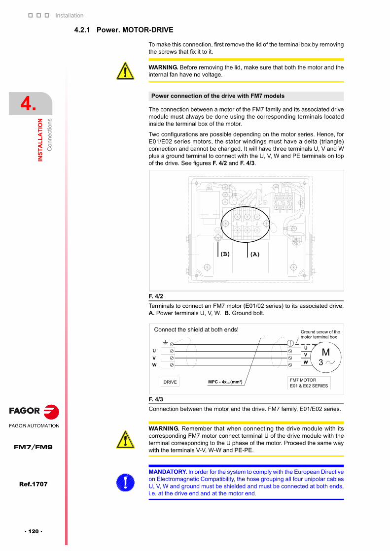
Installation
4.
INS
TA
LL
AT
ION
Co
nne
ctio
ns
146
Ref.1707
FM7/FM9
· 120 ·
4.2.1 Power. MOTOR-DRIVE
To make this connection, first remove the lid of the terminal box by removingthe screws that fix it to it.
The connection between a motor of the FM7 family and its associated drivemodule must always be done using the corresponding terminals locatedinside the terminal box of the motor.
Two configurations are possible depending on the motor series. Hence, forE01/E02 series motors, the stator windings must have a delta (triangle)connection and cannot be changed. It will have three terminals U, V and Wplus a ground terminal to connect with the U, V, W and PE terminals on topof the drive. See figures F. 4/2 and F. 4/3.
WARNING. Before removing the lid, make sure that both the motor and theinternal fan have no voltage.
Power connection of the drive with FM7 models
F. 4/2
Terminals to connect an FM7 motor (E01/02 series) to its associated drive.A. Power terminals U, V, W. B. Ground bolt.
F. 4/3
Connection between the motor and the drive. FM7 family, E01/E02 series.
(A)(B)
M3
U
MPC - 4x...(mm2)
V
W
U
V
W
DRIVE FM7 MOTOR
Ground screw of themotor terminal box
E01 & E02 SERIES
Connect the shield at both ends!
WARNING. Remember that when connecting the drive module with itscorresponding FM7 motor connect terminal U of the drive module with theterminal corresponding to the U phase of the motor. Proceed the same waywith the terminals V-V, W-W and PE-PE.
MANDATORY. In order for the system to comply with the European Directiveon Electromagnetic Compatibility, the hose grouping all four unipolar cablesU, V, W and ground must be shielded and must be connected at both ends,i.e. at the drive end and at the motor end.

Installation
INS
TA
LL
AT
ION
Co
nne
ctio
ns
4.
Ref.1707
· 121 ·
FM7/FM9
For E03/HS3 series motors of the FM7 family, the stator windings may beconfigured in a Y (star) or (triangle) connection. Hence, a unipolar cable isextended from each of the six terminals of the terminal box to two externalmagnetic contactors which will switch from one to the other type of connectionthrough an electrical maneuver.
The six terminals are defined by the labels U/U1, V/V1, W/W1, Z/W2, X/U2and Y/V2. It also has a ground bolt to connect the ground cable coming fromthe MPC power cable hose of the drive. The thee phase wires of this cablehose U, V and W must be connected to terminals U/U1, V/V1 and W/W1 ofthe terminal box of the motor. In turn, six cables go from these six terminalslocated inside the terminal box of the motor to two external magneticcontactors according to figure F. 4/12 to set the winding as star or delta.
NOTE. Observe that if the whole application needs a fixed windingconfiguration, make the desired winding connection (star or delta) shown infigure F. 4/4. See the diagram.
F. 4/4
Selecting the winding configuration with an electrical maneuver using twoexternal magnetic contactors. A. Star (Y), B. Triangle ().
F. 4/5
Terminals to connect an FM7 motor (E03/HS3 series) to its associated SCDdrive. A. Power terminales U/U1, V/V1, W/W1, Z/W2, X/U2 and Y/V2. B.Ground bolt.
(B)
(A)
UVW
U/U1
V/V1
W/W1
X/U2
Y/V2
Z/W2
UVW
U/U1
V/V1
W/W1
X/U2
Y/V2
Z/W2
Star (Y) connection
Terminal box
To the SPDor SCD
Terminal boxTriangle () connection
To the SPDor SCD drive
(A)
(B)

Installation
4.
INS
TA
LL
AT
ION
Co
nne
ctio
ns
146
Ref.1707
FM7/FM9
· 122 ·
FM9-B037-C5CX-E01 and FM9-B055-C5CX-E01-A
The connection between the modules of the FM9-B037 and FM9-B055motors and its associated drive module must always be done using thecorresponding terminals located inside the terminal box of the motor. Seefigure F. 4/6.
The stator windings have a Y (star) connection. It has three terminals U, V andW plus a ground terminal to connect with the U, V, W and PE terminals on topof the drive.
Power connection of the drive with FM9 models
F. 4/6
Terminals to connect an FM9 motor (E01 series, B037 and B055 models) toits associated drive. A. Power terminals U, V, W. B. Ground bolt.
F. 4/7
Power connection between motor and drive. FM9-B037 and FM9-B055models, E01 series.
(A)
(B)
Connect the shield at both ends!
Use a ring terminal type at the end of each wire (3 phases + PE) on themotor side to connect to the power terminals.
WARNING. Remember that when connecting the drive module with itscorresponding motor connect terminal U of the drive module with the terminalcorresponding to the U phase of the motor. Proceed the same way with theterminals V-V, W-W and PE-PE.
MANDATORY. In order for the system to comply with the European Directiveon Electromagnetic Compatibility, the MPC-4x... hose grouping all fourunipolar cables U, V, W and PE must be shielded and must be connected atboth ends, i.e. at the drive end and at the motor end.
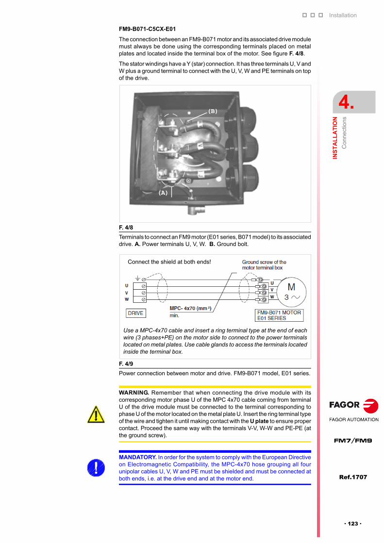
Installation
INS
TA
LL
AT
ION
Co
nne
ctio
ns
4.
Ref.1707
· 123 ·
FM7/FM9
FM9-B071-C5CX-E01
The connection between an FM9-B071 motor and its associated drive modulemust always be done using the corresponding terminals placed on metalplates and located inside the terminal box of the motor. See figure F. 4/8.
The stator windings have a Y (star) connection. It has three terminals U, V andW plus a ground terminal to connect with the U, V, W and PE terminals on topof the drive.
F. 4/8
Terminals to connect an FM9 motor (E01 series, B071 model) to its associateddrive. A. Power terminals U, V, W. B. Ground bolt.
F. 4/9
Power connection between motor and drive. FM9-B071 model, E01 series.
(A)
(B)
Connect the shield at both ends!
Use a MPC-4x70 cable and insert a ring terminal type at the end of eachwire (3 phases+PE) on the motor side to connect to the power terminalslocated on metal plates. Use cable glands to access the terminals locatedinside the terminal box.
WARNING. Remember that when connecting the drive module with itscorresponding motor phase U of the MPC 4x70 cable coming from terminalU of the drive module must be connected to the terminal corresponding tophase U of the motor located on the metal plate U. Insert the ring terminal typeof the wire and tighten it until making contact with the U plate to ensure propercontact. Proceed the same way with the terminals V-V, W-W and PE-PE (atthe ground screw).
MANDATORY. In order for the system to comply with the European Directiveon Electromagnetic Compatibility, the MPC-4x70 hose grouping all fourunipolar cables U, V, W and PE must be shielded and must be connected atboth ends, i.e. at the drive end and at the motor end.

Installation
4.
INS
TA
LL
AT
ION
Co
nne
ctio
ns
146
Ref.1707
FM7/FM9
· 124 ·
FM9-A100-C5CX-E01, FM9-B113-C5CX-E01 and FM9-A130-C5CX-E01
The connection between FM9-A100, FM9-B113 and FM9-A130 motors andtheir associated drive module must always be done using the correspondingterminals placed on metal plates and located inside the terminal box of themotor. See figure F. 4/10.
The stator windings have a Y (star) connection. It has three terminals U, Vand W plus a ground terminal to connect with the U, V, W and PE terminalson top of the drive.
F. 4/10
Terminals to connect an FM9 motor (E01 series, A100, B113 and A130 model)to its associated drive. A. Power terminals U, V, W. B. Ground bolt.
F. 4/11
Power connection between motor and drive. Models FM9-A100, FM9-B113and FM9-A130, E01 series.
(A)
(B)
Use two MPC-4x... cables and insert a ring terminal type at the end ofeach wire (3 phases+PE per cable) on the motor side to connect to thepower terminals located on metal plates. Use cable glands to access theterminals located inside the terminal box.
Connect the shields at both ends!
MANDATORY. Remember that when connecting the drive module with itscorresponding motor phase U of each MPC- 4x... cable coming fromterminal U of the drive module must be connected to the terminalcorresponding to phase U of the motor located on the metal plate U. Insertthe ring terminal type terminal of each wire, one on each side of the U plateand tighten it to ensure proper contact. Proceed the same way with theterminals V-V, W-W and PE-PE (at the ground screw).
MANDATORY. In order for the system to comply with the European Directiveon Electromagnetic Compatibility, each of the two MPC-4x... hoses groupingall four unipolar cables U, V, W and PE must be shielded and must beconnected at both ends, i.e. at the drive end and at the motor end.
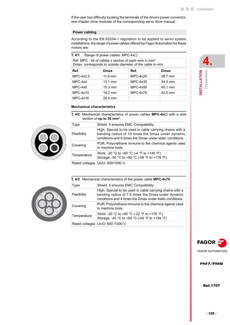
Installation
INS
TA
LL
AT
ION
Co
nne
ctio
ns
4.
Ref.1707
· 125 ·
FM7/FM9
If the user has difficulty locating the terminals of the drive's power connector,see chapter drive modules of the corresponding servo drive manual.
According to the EN 60204-1 regulation to be applied to servo systeminstallations, the range of power cables offered by Fagor Automation for thesemotors are:
Mechanical characteristics
Power cabling
T. 4/1 Range of power cables. MPC-4x.
Ref. MPC - Nr of cables x section of each wire in mm²Dmax. corresponds to outside diameter of the cable in mm.
Ref. Dmax Ref. Dmax
MPC-4x2.5 11.6 mm MPC-4x25 28.7 mm
MPC-4x4 13.1 mm MPC-4x35 34.0 mm
MPC-4x6 15.3 mm MPC-4x50 40.1 mm
MPC-4x10 19.2 mm MPC-4x70 42.5 mm
MPC-4x16 24.5 mm
T. 4/2 Mechanical characteristics of power cables MPC-4x with a wiresection of up to 50 mm².
Type Shield. It ensures EMC Compatibility.
FlexibilityHigh. Special to be used in cable carrying chains with abending radius of 10 times the Dmax under dynamicconditions and 6 times the Dmax under static conditions.
Covering PUR. Polyurethane immune to the chemical agents usedin machine tools.
Temperature Work: -20 °C to +60 °C (-4 °F to +140 °F)Storage: -50 °C to +80 °C (-58 °F to +176 °F)
Rated voltages Uo/U: 600/1000 V.
T. 4/3 Mechanical characteristics of the power cable MPC-4x70.
Type Shield. It ensures EMC Compatibility.
FlexibilityHigh. Special to be used in cable carrying chains with abending radius of 7.5 times the Dmax under dynamicconditions and 4 times the Dmax under static conditions.
Covering PUR. Polyurethane immune to the chemical agents usedin machine tools.
Temperature Work: -30 °C to +80 °C (-22 °F to +176 °F)Storage: -40 °C to +90 °C (-40 °F to +194 °F)
Rated voltages Uo/U: 600 /1000 V.

Installation
4.
INS
TA
LL
AT
ION
Co
nne
ctio
ns
146
Ref.1707
FM7/FM9
· 126 ·
Power cable section selection
Note that the sections given for three-phase lines in a PVC hose shown in thistable may be installed on a machine through conduits or channels exceptthose shown in bold letters. When installed under other more / less favorableconditions, some sections may be reduced/enlarged according to the EN60204-1 standard.
T. 4/4 Selection of the section of a unipolar unshielded cable in a three-phaseconfiguration depending on the current In (S1).
FM7---E01/E02Motor model In (S1) A Ref. of the power cableFM7-A037--E01/E02 12.5 MPC-4x2.5
FM7-A055--E01/E02 14.6 MPC-4x2.5
FM7-A075--E01/E02 19.8 MPC-4x4
FM7-A090--E01/E02 25.0 MPC-4x6
FM7-A110--E01/E02 28.0 MPC-4x6
FM7-A150--E01/E02 39.4 MPC-4x10
FM7-A185--E01/E02 47.5 MPC-4x16
FM7-A220--E01/E02 61.4 MPC-4x25
FM7-B120--E01/E02 35.0 MPC-4x10
FM7-B170--E01/E02 47.3 MPC-4x16
FM7-A300--E01 82.1 MPC-4x35
FM7-B220--E01 64.9 MPC-4x25
FM7-A370--E01 90.0 MPC-4x50
FM7-B280--E01 78.2 MPC-4x35
FM7-A510--E01/E02 115.2 MPC-4x70
FM7-C215--E01/E02 87.9 MPC-4x50
FM7-C270--E01/E02 117.0 MPC-4x70
FM7-E600-CB-E01 117.4 MPC-4x70
T. 4/5 Selection of the section of a unipolar unshielded cable in a three-phaseconfiguration depending on the current In (S1).
FM7-D-S1D0-E03/HS3Motor model In (S1) A
/Ref. of the power cable
FM7-D055-S1D0-E03 20.3 / 20.7 MPC-4x4
FM7-D075-S1D0-E03 26.5 / 25.8 MPC-4x6
FM7-D110-S1D0-E03 38.0 / 40.0 MPC-4x10
FM7-D150-S1D0-E03 46.4 / 45.7 MPC-4x16
FM7-D185-S1D0-E03 49.2 / 49.2 MPC-4x16
FM7-D220-S1D0-E03 62.3 / 61.7 MPC-4x25
FM7-D075-S1D0-HS3 26.5 / 25.8 MPC-4x6
FM7-D110-S1D0-HS3 38.0 / 40.0 MPC-4x10
FM7-D185-S1D0-HS3 49.2 / 49.2 MPC-4x16
FM7-D220-S1D0-HS3 62.3 / 61.7 MPC-4x25
T. 4/6 Selection of the section of a unipolar unshielded cable in a three-phase configuration depending on In (S1).
FM9--C5C-E01-Motor model In (S1) A Ref. of the power cable
FM9-B037-C5C-E01 74.7 MPC-4x35
FM9-B055-C5C-E01-A 104.4 MPC-4x50
FM9-B071-C5C-E01 134.8 MPC-4x70
FM9-A100-C5C-E01 189.9 2x MPC-4x50
FM9-B113-C5C-E01 214.6 2x MPC-4x70
FM9-A130-C5C-E01 246.9 2x MPC-4x70
INFORMATION. Note that all the references of the power cables for theFM7/FM9 motors always have 4 wires. They will never have 6 wires becausethese motors do not have a brake.
i

Installation
INS
TA
LL
AT
ION
Co
nne
ctio
ns
4.
Ref.1707
· 127 ·
FM7/FM9
Either an external auxiliary power supply or a FAGOR power supply may be used to supply the 24 V DC. NEVERCONNECT BOTH AT THE SAME TIME !
To brake the motor in a controlled way during a power failure, make sure that 24 V DC will be supplied to contactorsK1 and K2 and relays K3 and K4. This situation is ensured if you have installed a FAGOR power supply next to anSPD modular drive. If you have installed an external auxiliary 24 V DC power supply, you must make sure that thiscondition is ensured.
When using a compact SCD drive to govern a spindle motor, you must necessarily install an external auxiliarypower supply to provide the 24 V DC. These compact drives do not have an output 24 V DC connector.
Always join all the GND of different remote I/O modules together. The GND of the same module are alreadyconnected to each other internally.
It is better to power the POWER SUPPLY module with an external auxiliary power supply and the DIGITALOUTPUT module with another one. If there is only one external auxiliary power supply, always join its 24 V DC withthe 24 V DC of the POWER SUPPLY module and of each module.
Note. See the rated currents in the selection chapter of this manual.
Note. See the necessary cable section in the corresponding section of this chapter.
Diagram for the electrical maneuver of the on-the-fly Y- switching winding
F. 4/12
Connection between the motor and the drive. FM7 family, E03/HS3 series. Diagram for the on-the-fly Y- switching of the winding configuration.
Important warnings
DIGITAL INPUT
X1
X2
GND
I8
I1
N.C.
I2
I3
I4
I5
I6
I7
GND
I16
I9
N.C.
I10
I11
I12
I13
I14
I15
DIGITAL OUTPUT
X1
X2
GND
O8
O1
+24V
O2
O3
O4
O5
O6
O7
GND
O16
O9
+24V.
O10
O11
O12
O13
O14
O15
POWER SUPPLYFAGOR
SPD DRIVE
PS
-65A
+ A
PS
24 (
X2,
X3
& X
4)
24 V
DC
, 10
AP
S-2
5B4
(X4,
X5
& X
6) 2
4 V
DC
, 10
AX
PS
-XX
(X
4, X
5 &
X6
) 24
V D
C,
8 A
RP
S-X
X (
X2
) 24
V D
C, 8
A K2
Star
K1Delta
MPC- 4xN2
U/U1V/V1 W/W1
U
V
W
MCP- 4xN1
MPC- 4xN1
MPC- 4xN1 MPC- 4xN1
M3
MPC- 4xN1
X/U2 Y/V2 Z/W2
A1
A2
K1
K3K2
K1D3
K4
*
GND
CAN L
SHIELD
SHIELD
CAN H
X3
GND
CAN L
SHIELD
SHIELD
CAN H
X2
POWER SUPPLY
4
01
F
DCB
98
7
5 3
ADD MSB
LINE TERM
10
12
ADDRESS
RESET
POWER
SYSTEM READY
+5 ERROR
+5 OVER CURRENT
OVER VOLTAGE+5V
X1
GND INCHASIS
GND IN+24V IN
SYSTEM
READY
K1
K2
A1
A2
K4D3
K3
Auxiliary relays K3, K4. e.g. RP821024Flywheel diodes D3, D4. e.g. 1N4934
EXTERNALAUXILIARYPOWERSUPPLY
24 V
24 V0 V
OUTPUT 24 V DC
Chassis
THE STAR/DELTA SWITCH IS MANAGEDBY THE PLC PROGRAM AT THE 8070 CNC
24 V
0 V
0 V
24 V
A1
A2
D4
0 V
I1
I2
O1
O2
REMOTE I/O
A1
A2
K2
Flywheel diode1N4934
CANFagorINTERFACE
0 V
24 V
D4Flywheel diode1N4934
24 V DC (of the FAGOR power supply)
*0 V DC (of the FAGOR power supply)
(*) WARNING. Never connect anexternal auxiliary power supply anda Fagor power supply at the sametime.
WARNING. If you decide to install anexternal power supply, make sure that incase of a power outage, the 24 V DC areensured to brake the motor under controlpreventing it from braking by inertia. Ignoringthis warning may cause personal injury !
Only on FM7 motors, E03/HS3 series !
Sizing of power contactors K1 and K2
Sizing of motor power cables
Contactor K1: I(K1) > IN ( )
Contactor K2: I(K2) > (1/ ) IN ( ) 3
MPC- 4xN1 N1: section supporting IN ( )MPC- 4xN2 N2: section supporting IN ( )
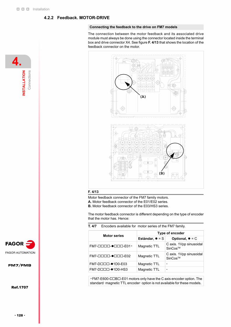
Installation
4.
INS
TA
LL
AT
ION
Co
nne
ctio
ns
146
Ref.1707
FM7/FM9
· 128 ·
4.2.2 Feedback. MOTOR-DRIVE
The connection between the motor feedback and its associated drivemodule must always be done using the connector located inside the terminalbox and drive connector X4. See figure F. 4/13 that shows the location of thefeedback connector on the motor.
The motor feedback connector is different depending on the type of encoderthat the motor has. Hence:
Connecting the feedback to the drive on FM7 models
F. 4/13
Motor feedback connector of the FM7 family motors.A. Motor feedback connector of the E01/E02 series. B. Motor feedback connector of the E03/HS3 series.
T. 4/7 Encoders available for motor series of the FM7 family.
Motor seriesType of encoder
Estándar, = S Optional, = C
FM7---E01* Magnetic TTLC axis. 1Vpp sinusoidal SinCosTM
FM7---E02 Magnetic TTLC axis. 1Vpp sinusoidal SinCosTM
FM7-D-1D0-E03 Magnetic TTL -
FM7-D-1D0-HS3 Magnetic TTL -
*FM7-E600-CB-E01 motors only have the C axis encoder option. Thestandard ·magnetic TTL encoder· option is not available for these models.
(A)
(B)
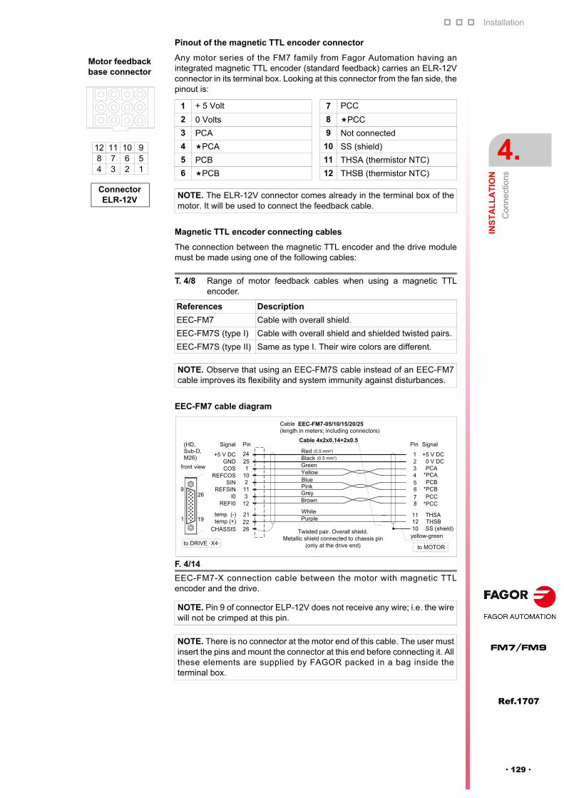
Installation
INS
TA
LL
AT
ION
Co
nne
ctio
ns
4.
Ref.1707
· 129 ·
FM7/FM9
Pinout of the magnetic TTL encoder connector
Any motor series of the FM7 family from Fagor Automation having anintegrated magnetic TTL encoder (standard feedback) carries an ELR-12Vconnector in its terminal box. Looking at this connector from the fan side, thepinout is:
Magnetic TTL encoder connecting cables
The connection between the magnetic TTL encoder and the drive modulemust be made using one of the following cables:
EEC-FM7 cable diagram
1 + 5 Volt 7 PCC
2 0 Volts 8 PCC
3 PCA 9 Not connected
4 PCA 10 SS (shield)
5 PCB 11 THSA (thermistor NTC)
6 PCB 12 THSB (thermistor NTC)
NOTE. The ELR-12V connector comes already in the terminal box of themotor. It will be used to connect the feedback cable.
T. 4/8 Range of motor feedback cables when using a magnetic TTLencoder.
References Description
EEC-FM7 Cable with overall shield.
EEC-FM7S (type I) Cable with overall shield and shielded twisted pairs.
EEC-FM7S (type II) Same as type I. Their wire colors are different.
NOTE. Observe that using an EEC-FM7S cable instead of an EEC-FM7cable improves its flexibility and system immunity against disturbances.
F. 4/14
EEC-FM7-X connection cable between the motor with magnetic TTLencoder and the drive.
NOTE. Pin 9 of connector ELP-12V does not receive any wire; i.e. the wirewill not be crimped at this pin.
NOTE. There is no connector at the motor end of this cable. The user mustinsert the pins and mount the connector at this end before connecting it. Allthese elements are supplied by FAGOR packed in a bag inside theterminal box.
Connector ELR-12V
12 11 10 98 7 6 54 3 2 1
Motor feedback base connector
�
�
� �
� �
� � �
� � �
� � � �
� � � �
� � � � � �
� � � � � �
� � � � �
� � � � �
� � � � � � � � � � � � � � � � � � � �
� � � � ! � � � � " � � � � # $ � � % � � & � � ! % � � � � % � � � # �
'
(
)
*
�
�
� �
+
, - �
� .
/ 0 1 � .
2 -
/ 0 1 2 -
2 3
� � 4 2
� � " � � �
/ 0 1 2 3
5 ( 6 � �
�� �
�
� 3
�
� (
� )
� �
� �
� �
*
� �
, � � � �
, � � 7
� � � � � � � � � � � � � � � � � �
� ! � � � � � � � � �
8 � � # � � & � � � � 9 . : � � � � � # � � � � & 9
� � � � � � � % # � � � � & % � � � � % � � & � � % � � # # � # � � �
� � � � 7 � � � � � & � � : � � � & �
� � " � � 5 �
; � � � � : � � �
� � � / 2 6 0 < = ) <
� � � . 8 . /
� � � >
� �
� 3
3 6 � �
� � 4
? � � 4
� � �
? � � �
� � �
8 � 4
8 � �
5 ( 6 � �
� ! � � �
� # � � � � & �
/ � &
� � � % >
� 3 9 ( " "��
� 3 9 ( " "��
7 � � � � � ! � � � �
? � � �
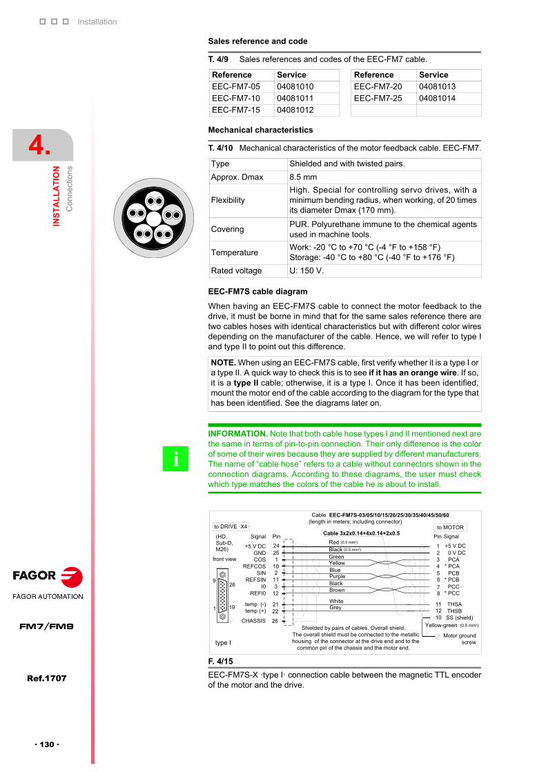
Installation
4.
INS
TA
LL
AT
ION
Co
nne
ctio
ns
146
Ref.1707
FM7/FM9
· 130 ·
Sales reference and code
Mechanical characteristics
EEC-FM7S cable diagram
When having an EEC-FM7S cable to connect the motor feedback to thedrive, it must be borne in mind that for the same sales reference there aretwo cables hoses with identical characteristics but with different color wiresdepending on the manufacturer of the cable. Hence, we will refer to type Iand type II to point out this difference.
T. 4/9 Sales references and codes of the EEC-FM7 cable.
Reference Service Reference Service
EEC-FM7-05 04081010 EEC-FM7-20 04081013
EEC-FM7-10 04081011 EEC-FM7-25 04081014
EEC-FM7-15 04081012
T. 4/10 Mechanical characteristics of the motor feedback cable. EEC-FM7.
Type Shielded and with twisted pairs.
Approx. Dmax 8.5 mm
FlexibilityHigh. Special for controlling servo drives, with aminimum bending radius, when working, of 20 timesits diameter Dmax (170 mm).
CoveringPUR. Polyurethane immune to the chemical agentsused in machine tools.
TemperatureWork: -20 °C to +70 °C (-4 °F to +158 °F)Storage: -40 °C to +80 °C (-40 °F to +176 °F)
Rated voltage U: 150 V.
NOTE. When using an EEC-FM7S cable, first verify whether it is a type I ora type II. A quick way to check this is to see if it has an orange wire. If so,it is a type II cable; otherwise, it is a type I. Once it has been identified,mount the motor end of the cable according to the diagram for the type thathas been identified. See the diagrams later on.
INFORMATION. Note that both cable hose types I and II mentioned next arethe same in terms of pin-to-pin connection. Their only difference is the colorof some of their wires because they are supplied by different manufacturers.The name of “cable hose” refers to a cable without connectors shown in theconnection diagrams. According to these diagrams, the user must checkwhich type matches the colors of the cable he is about to install.
i
F. 4/15
EEC-FM7S-X ·type I· connection cable between the magnetic TTL encoderof the motor and the drive.
�
�
� �
� �
� � �
� � �
� � � �
� � � �
, � � � �
, � � 7
� � � � �
� � � � �
� � � � � � � � � � � � � � � � � � � � � � � � � � � � � � � �
� � � � ! � � � � " � � � � # $ � � % � � & � � ! % � � � � % � � � �
'
(
)
*
�
�
� �
+
, - �
� .
/ 0 1 � .
2 -
/ 0 1 2 -
2 3
� � 4 2
� � " � � �
/ 0 1 2 3
5 ( 6 � �
�� �
�
� 3
�
� (
� )
� �
� �
� �
*
� �
� � � � � �
� � � % >
� � � � � � � � � � � � � � � � � � � � � � � � �
� ! � � � � � � � � �
� � � � & � & � 7 � � � � # � ; % � � � � # 9 . : � � � � � # � � � � & 9
8 � � � : � � � � � # � � � � & " � # � � � % � � � � % � � & � � � � � " � � � � � � %
� � � # � � ! � ; � � � % � � � � % � � � � � � � � & � � : � � � & � � & � � � � �
% � " " � � � � � � ; � � � % � � # # � # � � & � � � " � � � � � � & 9
� � " � � 5 �
; � � � � : � � �
� � � / 2 6 0 < = ) < � � � . 8 . /
� � � � � �
� �
� 3
3 6 � �
? � � 4
� � �
? � � �
� � �
8 � 4
8 � �
? � � �
5 ( 6 � �
� ! � � �
� # � � � � & �
/ � &
� � � % >
� � � � � ! � � � � &
# % � � �
� � � � � � ! � � � �
� 3 9 ( " "��
� 3 9 ( " "��
� � 4
� 3 9 ( " "��
type I
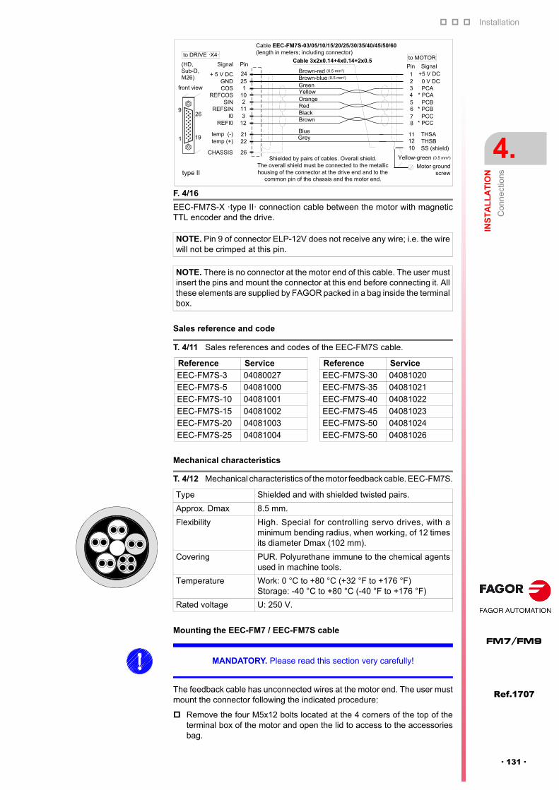
Installation
INS
TA
LL
AT
ION
Co
nne
ctio
ns
4.
Ref.1707
· 131 ·
FM7/FM9
Sales reference and code
Mechanical characteristics
Mounting the EEC-FM7 / EEC-FM7S cable
The feedback cable has unconnected wires at the motor end. The user mustmount the connector following the indicated procedure:
Remove the four M5x12 bolts located at the 4 corners of the top of theterminal box of the motor and open the lid to access to the accessoriesbag.
F. 4/16
EEC-FM7S-X ·type II· connection cable between the motor with magneticTTL encoder and the drive.
NOTE. Pin 9 of connector ELP-12V does not receive any wire; i.e. the wirewill not be crimped at this pin.
NOTE. There is no connector at the motor end of this cable. The user mustinsert the pins and mount the connector at this end before connecting it. Allthese elements are supplied by FAGOR packed in a bag inside the terminalbox.
T. 4/11 Sales references and codes of the EEC-FM7S cable.
Reference Service Reference Service
EEC-FM7S-3 04080027 EEC-FM7S-30 04081020
EEC-FM7S-5 04081000 EEC-FM7S-35 04081021
EEC-FM7S-10 04081001 EEC-FM7S-40 04081022
EEC-FM7S-15 04081002 EEC-FM7S-45 04081023
EEC-FM7S-20 04081003 EEC-FM7S-50 04081024
EEC-FM7S-25 04081004 EEC-FM7S-50 04081026
T. 4/12 Mechanical characteristics of the motor feedback cable. EEC-FM7S.
Type Shielded and with shielded twisted pairs.
Approx. Dmax 8.5 mm.
Flexibility High. Special for controlling servo drives, with aminimum bending radius, when working, of 12 timesits diameter Dmax (102 mm).
Covering PUR. Polyurethane immune to the chemical agentsused in machine tools.
Temperature Work: 0 °C to +80 °C (+32 °F to +176 °F)Storage: -40 °C to +80 °C (-40 °F to +176 °F)
Rated voltage U: 250 V.
�
�
� �
� �
� � �
� � �
� � � �
. � � � ! �
, � � � �
, � � 7
� � � �
� � � � �
� � � � � � � � � � � � � � � � � � � � � � � � � � � � � � � � �
� � � � ! � � � � " � � � � # $ � � % � � & � � ! % � � � � % � � � �
'
(
)
*
�
�
� �
+
, - �
� .
/ 0 1 � .
2 -
/ 0 1 2 -
2 3
� � 4 2
� � " � � �
/ 0 1 2 3
5 ( 6 � �
�� �
�
� 3
�
� (
� )
� �
� �
� �
*
� �
� � � � � �
� � � % >
� � � � � � � � � � � � � � � � � � � � � � � � �
� ! � � � � � �� � �
� � � � & � & � 7 � � � � # � ; % � � � � # 9 . : � � � � � # � � � � & 9
8 � � � : � � � � � # � � � � & " � # � � � % � � � � % � � & � � � � � " � � � � � � %
� � � # � � ! � ; � � � % � � � � % � � � � � � � � & � � : � � � & � � & � � � � �
% � " " � � � � � � ; � � � % � � # # � # � � & � � � " � � � � � � & 9
� � " � � 5 �
; � � � � : � � �
� � � / 2 6 0 < = ) <� � � . 8 . /
/ � &
� �
� 3
3 6 � �
? � � 4
� � �
? � � �
� � �
8 � 4
8 � �
? � � �
5 ( 6 � �
� ! � � �
� # � � � � & �
� � � � � � � &
� � � � � � � � �
� � � � � ! � � � � &
# % � � �
� � � � � � ! � � � �
� 3 9 ( " "��
� � 4
� 3 9 ( " "��
� 3 9 ( " "��
type II
MANDATORY. Please read this section very carefully!

Installation
4.
INS
TA
LL
AT
ION
Co
nne
ctio
ns
146
Ref.1707
FM7/FM9
· 132 ·
Unpack the bag supplied by FAGOR containing 11 pins SLF-01T and thebody of connector ELP-12V.
Crimp the end of each wire with each SLF-01T pin.
Insert each wire end already crimped into its corresponding pin of thebody of connector ELP-12V supplied as accessory.
Insert the body of the connector ELP-12V already attached to thefeedback cable into the socket of connector ERL-12V of the terminal boxto make the connection with the feedback device.
NOTE. Do not insert the body of the connector ELP-12V supplied asaccessory into connector ERL-12V of the terminal box without previouslymaking the connection cable.
F. 4/17
Mounting the EEC-FM7 or EEC-FM7S cable. Accessories: A. Body of connector ELP-12V. B. SLF-01T pins.
NOTE. Be careful with the wires being crimped with each terminalbecause there are 11 pins and 12 wires. One of them must not beconnected and therefore will not have a pin to be crimped. See the cablediagram to know which wire it is and be careful with the colors.
NOTE. Make sure that each pin is inserted into the corresponding pinof connector ELP-12V. If the user makes a mistake, it is difficult to recoverthe pin in its best shape. Carefully follow the connection diagram and thenumbering of pins of connector ELP-12V. The tab marked with a circlein figure F. 4/18 must be at the bottom when making the connection.
F. 4/18
Accessories: A. Body of connector ELP-12V. B. SLF-01T pins.
NOTE. Make sure that the tab at the bottom of the body of the connectorELP-12V clicks when connecting it. This click ensures that it has beeninserted properly.
EEC-FM7/EEC-FM7S feedback cables
ELP-12V
ELR-12V
ELP-12V
Do not insert the ELP-12Vconnector into the ELR-12Vof the motor without havingpreviously joined the wiresof the feedback cable.
(A)(B)
19,3
(0,
760
)
14,6 (0,575)
24,6 (0,969)
12
9 1
4
14,8 (0,583)
11.3 (.445)
17.7 (.697)
2.0(.079)
2.3(.091)
(A)
(B)

Installation
INS
TA
LL
AT
ION
Co
nne
ctio
ns
4.
Ref.1707
· 133 ·
FM7/FM9
Pinout of the C axis encoder connector
Any motor series of the FM7 family from Fagor Automation having anintegrated C axis SinCosTM encoder (optional feedback) carries an ELR-12Vconnector in its terminal box. Looking at this connector from the fan side, thepinout is:
C axis SinCosTM encoder connecting cables
The connection between the C axis SinCosTM encoder and the drive modulemust be made using one of the following cables:
F. 4/19
A. Connector ELR-12V. B. Body of connector ELP-12V.
Before making this connection, the body of the connector ELP-12V (B) must be attached to the feedback cable !
Location of connector ELR-12Vfor the E01/E02 series of the FM7family.
EEC-FM7/EEC-FM7S feedback cables
ELR-12V
ELP-12V(A)
(B)
Location of connector ELR-12Vfor the E03/HS3 series of the FM7family.
WARNING. When having to extract the body of the connector ELP-12V fromthe socket of the connector of the encoder ELR-12V, make sure that themotor is not powered, push the tab at the bottom (not visible) up and pull it.Never pull the cable because it could damage it!
1 + 8 Volt 7 + 485
2 0 Volts 8 - 485
3 SIN 9 SS (shield)
4 REFSIN 10 Not connected
5 COS 11 THSA (thermistor NTC)
6 REFCOS 12 THSB (thermistor NTC)
NOTE. The ELR-12V connector comes already in the terminal box of themotor and it is rotated 180° with respect to that of the magnetic TTLencoder (standard). It will be used to connect the feedback cable.
T. 4/13 Range of motor feedback cables when using a C axis encoder.
References Description
EEC-FM7CS (type I) Cable with overall shield & shielded twisted pairs.
EEC-FM7CS (type II) Same as type I. Their wire colors are different.
Connector ELR-12V
1 2 3 45 6 7 89 10 11 12
Motor feedback base connector
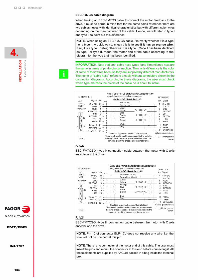
Installation
4.
INS
TA
LL
AT
ION
Co
nne
ctio
ns
146
Ref.1707
FM7/FM9
· 134 ·
EEC-FM7CS cable diagram
When having an EEC-FM7CS cable to connect the motor feedback to thedrive, it must be borne in mind that for the same sales reference there aretwo cables hoses with identical characteristics but with different color wiresdepending on the manufacturer of the cable. Hence, we will refer to type Iand type II to point out this difference.
NOTE. When using an EEC-FM7CS cable, first verify whether it is a typeI or a type II. A quick way to check this is to see if it has an orange wire.If so, it is a type II cable; otherwise, it is a type I. Once it has been identifiedas type I or type II, mount the motor end of the cable according to thediagram for the type that has been identified.
INFORMATION. Note that both cable hose types I and II mentioned next arethe same in terms of pin-to-pin connection. Their only difference is the colorof some of their wires because they are supplied by different manufacturers.The name of “cable hose” refers to a cable without connectors shown in theconnection diagrams. According to these diagrams, the user must checkwhich type matches the colors of the cable he is about to install.
i
F. 4/20
EEC-FM7CS-X ·type I· connection cable between the motor with C axisencoder and the drive.
F. 4/21
EEC-FM7CS-X ·type II· connection cable between the motor with C axisencoder and the drive.
NOTE. Pin 10 of connector ELP-12V does not receive any wire; i.e. thewire will not be crimped at this pin.
NOTE. There is no connector at the motor end of this cable. The user mustinsert the pins and mount the connector at this end before connecting it. Allthese elements are supplied by FAGOR packed in a bag inside the terminalbox.
�
�
� �
� �
� � �
� � �
� � � �
� � � �
, � � � �
, � � 7
� � � � �
� � � � �
� � � � � � � � � � � � � � � � � � � � � � � � � � � � �
� � � � ! � � � � " � � � � # $ � � % � � & � � ! % � � � � % � � � �
'
*
�
(
�
�
� �
+
, - �
� .
/ 0 1 � .
2 -
/ 0 1 2 -
5 ) + (
� � 4 2
� � " � � �
5 + 6 � �
)� �
�
� 3
�
� (
� *
� �
� �
� �
� �
� 3
� � � � � �
� � � % >
� � � � � � � � � � � � � � � � � � � � � � � � �
� ! � � � � � � � � �
� � � � & � & � 7 � � � � # � ; % � � � � # 9 . : � � � � � # � � � � & 9
8 � � � : � � � � � # � � � � & " � # � � � % � � � � % � � & � � � � � " � � � � � � %
� � � # � � ! � ; � � � % � � � � % � � � � � � � � & � � : � � � & � � & � � � � �
% � " " � � � � � � ; � � � % � � # # � # � � & � � � " � � � � � � & 9
� � " � � 5 �
; � � � � : � � �
� � � / 2 6 0 < = ) <� � � . 8 . /
� � � � � �
� �
�
3 6 � �
8 � 4
8 � �
5 + 6 � �
� ! � � �
� # � � � � & �
/ � &
� � � % >
� � � � � ! � � � � &
# % � � �
� � � � � � ! � � � �
� 3 9 ( " "��
� 3 9 ( " "��
) + ( ) + (
5 ) + (
/ 0 1 2 -
2 -
/ 0 1 � .
� .
� 3 9 ( " "��
type I
�
�
� �
� �
� � �
� � �
� � � �
. � � � ! �
, � � � �
, � � 7
� � � �
� � � � �
� � � � � � � � � � � � � � � � � � � � � � � � � � � � � �
� � � � ! � � � � " � � � � # $ � � % � � & � � ! % � � � � % � � � �
'
*
�
(
�
�
� �
+
, - �
� .
/ 0 1 � .
2 -
/ 0 1 2 -
5 ) + (
� � 4 2
� � " � � �
5 + 6 � �
)� �
�
� 3
�
� (
� *
� �
� �
� �
� �
� 3
� � � � � �
� � � % >
� � � � � � � � � � � � � � � � � � � � � � � � �
� ! � � � � � � � � �
� � " � � 5 �
; � � � � : � � �
� � � / 2 6 0 < = ) <� � � . 8 . /
/ � &
� �
�
3 6 � �
5 ) + (
8 � 4
8 � �
5 + 6 � �
� ! � � �
� # � � � � & �
� � � � � � � &
� � � � � � � � �
� � � � � ! � � � � &
# % � � �
� � � � � � ! � � � �
� 3 9 ( " "��
� 3 9 ( " "��
) + (
/ 0 1 � .
� .
2 -
/ 0 1 2 -
) + (
� � � � & � & � 7 � � � � # � ; % � � � � # 9 . : � � � � � # � � � � & 9
8 � � � : � � � � � # � � � � & " � # � � � % � � � � % � � & � � � � � " � � � � � � %
� � � # � � ! � ; � � � % � � � � % � � � � � � � � & � � : � � � & � � & � � � � �
% � " " � � � � � � ; � � � % � � # # � # � � & � � � " � � � � � � & 9
� 3 9 ( " "��
type II

Installation
INS
TA
LL
AT
ION
Co
nne
ctio
ns
4.
Ref.1707
· 135 ·
FM7/FM9
Mechanical characteristics
Assembling the EEC-FM7CS cable
The feedback cable has unconnected wires at the motor end. The user mustmount the connector following the indicated procedure:
Remove the four M5x12 bolts located at the 4 corners of the top of theterminal box of the motor and open the lid to access to the accessoriesbag.
Unpack the bag supplied by FAGOR containing 11 pins SLF-01T and thebody of connector ELP-12V.
Crimp the end of each wire with each SLF-01T pin.
Insert each wire end already crimped into its corresponding pin of thebody of connector ELP-12V supplied as accessory.
T. 4/14 Mechanical characteristics of the motor feedback cable. EEC-FM7CS.
Type Shielded and with shielded twisted pairs.
Approx. Dmax 8.5 mm
FlexibilityHigh. Special for controlling servo drives, with aminimum bending radius, when working, of 12 timesits diameter Dmax (102 mm).
CoveringPUR. Polyurethane immune to the chemical agentsused in machine tools.
TemperatureWork: 0 °C to +80 °C (+32 °F to +176 °F)Storage: -40 °C to +80 °C (-40 °F to +176 °F)
Rated voltage U: 250 V.
MANDATORY. Please read this section very carefully!
NOTE. Do not insert the body of the connector ELP-12V supplied asaccessory into connector ERL-12V of the terminal box without previouslymaking the connection cable.
F- 4.22
Assembling the EEC-FM7CS cable. Accessories: A. Body of connector ELP-12V. B. SLF-01T pins.
NOTE. Be careful with the wires being crimped with each terminalbecause there are 11 pins and 12 wires. One of them must not beconnected and therefore will not have a pin to be crimped. See the cablediagram to know which wire it is and be careful with the colors.
NOTE. Make sure that each pin is inserted into the corresponding pinof connector ELP-12V. If the user makes a mistake, it is difficult torecover the pin in its best shape. Carefully follow the connection diagram and the numbering of pins ofconnector ELP-12V. The tab marked with a circle in figure F. 4/23 mustbe at the top when making the connection.
EEC-FM7CS feedback cable
ELP-12V
ELR-12V
ELP-12V
Do not insert the ELP-12Vconnector into the ELR-12Vof the motor without havingpreviously joined the wires ofthe feedback cable.
(B)(A)

Installation
4.
INS
TA
LL
AT
ION
Co
nne
ctio
ns
146
Ref.1707
FM7/FM9
· 136 ·
Insert the body of the connector ELP-12V already attached to thefeedback cable into the socket of connector ERL-12V of the terminal boxto make the connection with the feedback device.
F. 4/23
Accessories: A. Body of connector ELP-12V. B. SLF-01T pins.
NOTE. Make sure that the tab at the top of the body of the connectorELP-12V clicks when connecting it. This click ensures that it has beeninserted properly.
F. 4/24
A. Connector ELR-12V. B. Body of connector ELP-12V.
19,3
(0,
760
)
14,6 (0,575)
24,6 (0,969)
12
9 1
4
14,8 (0,583)
11.3 (.445)
17.7 (.697)
2.0(.079)
2.3(.091)
(A)
(B)
Location of connector ELR-12Vfor the E01/E02 series of the FM7family.
Location of connector ELR-12Vfor the E03/HS3 series of the FM7family.
Before making this connection, the body of the connector ELP-12V (B)must be attached to the feedback cable!
EEC-FM7CS feedback cable
(A)
(B)
WARNING. When having to extract the body of connector ELP-12V from thehousing of the connector of the ELR-12V encoder, make sure that the motoris without power. Press the tab on the top (not visible) down and pull at it.Never pull the cable because it could damage it.

Installation
INS
TA
LL
AT
ION
Co
nne
ctio
ns
4.
Ref.1707
· 137 ·
FM7/FM9
The connection between the motor feedback and its associated drivemodule must always be done using the connector located outside theterminal box and the connector of the motor feedback at the drive. See figureF. 4/25 that shows the location of the feedback connector on the motordepending on model.
Available encoders
Connecting the feedback to the drive on FM9 models
F. 4/25
Motor feedback connector of the FM9 family motors.A. Motor feedback connector on B037, B055 models. B. Motor feedback connector on B071, A100, B113, A130 models.
T. 4/15 Encoders available for FM9 motors.
Motor seriesType of encoder
Estándar, = C
FM9---E01C axis. 1 Vpp sinusoidal SinCosTM encoder. 1024 ppt
(A)
(B)

Installation
4.
INS
TA
LL
AT
ION
Co
nne
ctio
ns
146
Ref.1707
FM7/FM9
· 138 ·
Pinout of the connector of the C axis SinCosTM encoder
Any motor series of the FM9 family from Fagor Automation having anintegrated C axis SinCosTM encoder (optional feedback) carries an EOC-12base connector in its terminal box. Looking at this connector, the pinout is:
C axis SinCosTM encoder connecting cables
The connection between the C axis SinCosTM encoder and the drive modulemust be made using one of the following cables. Note that the motorfeedback will be wired differently depending on the drive model it will beconnected to.
EEC-SP cable diagram
Sales reference and code
1 REFCOS 7 - 485
2 + 485 8 COS
3 KTY84 - 9 SS (shield) + CHASSIS
4 KTY84 + 10 GND
5 SIN 11 N C (Not Connected)
6 REFSIN 12 + 8 V DC
T. 4/16 Range of motor feedback cables when using a C axis SinCosTM
encoder.
Drive model
Cable reference
Description
SPD series EEC-SPCable with overall shield and shielded twisted pairs
CT series EEC-SP +CA-EEC-CT
Cable with overall shield and shieldedtwisted pairs + adapter cable
F. 4/26
EEC-SP motor connection cable with a C axis SinCosTM encoder directly tothe drive (SPD series) or indirectly to the drive (through a CA-EEC-CTadapter).
T. 4/17 Sales references and codes of the EEC-SP cable.
Reference Service Reference Service
EEC-SP-5 04080020 EEC-SP-30 04080060
EEC-SP-10 04080021 EEC-SP-35 04080061
EEC-SP-15 04080022 EEC-SP-40 04080062
EEC-SP-20 04080023 EEC-SP-45 04080063
EEC-SP-25 04080024 EEC-SP-50 04080064
EOC 12connector
Motor feedback base connector
(HD,Sub-D,M26)
Ready Made Cable EEC-SP 5/10/15/20/25/30/35/40/45/50Length in meters; connectors included
10
26518
34
12
REFCOSSIN
REFSIN+485-485GND
KTY84 -KTY84 +
+8 V
COS
72019112101
2122
26
2523
9
Cable 3x2x0.14+4x0.14+2x0.5Signal Pin Pin
CHASSIS
E0C 12
123
411
101278
65
9
Front view
Front view
to DRIVE
to MOTOR
(0.5 mm2)
(0.5 mm2)
Shielded by pairs of cables and overall shield.The shields of twister pairs must be connected to each other and only at the driveend joined to the common pin of the chassis (pin 26). The overall screen must beconnected to the connector housing at the drive end and to the metallic housing
and to pin 9 of the connector at the motor end. The housing of the 26-pin connector must be conductive (metallic).
9
1
26
19
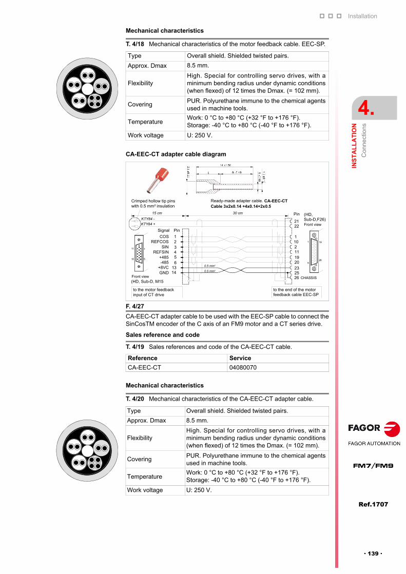
Installation
INS
TA
LL
AT
ION
Co
nne
ctio
ns
4.
Ref.1707
· 139 ·
FM7/FM9
Mechanical characteristics
CA-EEC-CT adapter cable diagram
Sales reference and code
Mechanical characteristics
T. 4/18 Mechanical characteristics of the motor feedback cable. EEC-SP.
Type Overall shield. Shielded twisted pairs.
Approx. Dmax 8.5 mm.
FlexibilityHigh. Special for controlling servo drives, with aminimum bending radius under dynamic conditions(when flexed) of 12 times the Dmax. (= 102 mm).
CoveringPUR. Polyurethane immune to the chemical agentsused in machine tools.
TemperatureWork: 0 °C to +80 °C (+32 °F to +176 °F).Storage: -40 °C to +80 °C (-40 °F to +176 °F).
Work voltage U: 250 V.
F. 4/27
CA-EEC-CT adapter cable to be used with the EEC-SP cable to connect theSinCosTM encoder of the C axis of an FM9 motor and a CT series drive.
T. 4/19 Sales references and code of the CA-EEC-CT cable.
Reference Service
CA-EEC-CT 04080070
T. 4/20 Mechanical characteristics of the CA-EEC-CT adapter cable.
Type Overall shield. Shielded twisted pairs.
Approx. Dmax 8.5 mm.
FlexibilityHigh. Special for controlling servo drives, with aminimum bending radius under dynamic conditions(when flexed) of 12 times the Dmax. (= 102 mm).
CoveringPUR. Polyurethane immune to the chemical agentsused in machine tools.
TemperatureWork: 0 °C to +80 °C (+32 °F to +176 °F).Storage: -40 °C to +80 °C (-40 °F to +176 °F).
Work voltage U: 250 V.
(HD, Sub-D, M15
23
2101
2122
25
REFCOSSIN
REFSIN+485-485
+8VCGND
COS
654321
1314
Signal Pin
Pin
Front view
to the motor feedback input of CT drive
KTY84 +
16
(HD,Sub-D,F26)Front view
to the end of the motorfeedback cable EEC-SP
10
10515
11
19
26
1
918
Ready-made adapter cable. CA-EEC-CT
201911
26 CHASSIS
Cable 3x2x0.14 +4x0.14+2x0.5
30 cm
KTY84 -
0.5 mm2
0.5 mm2
15 cm
Crimped hollow tip pinswith 0.5 mm² insulation

Installation
4.
INS
TA
LL
AT
ION
Co
nne
ctio
ns
146
Ref.1707
FM7/FM9
· 140 ·
Connection of the motor feedback with CT series drives
The motor feedback of FM9 spindles to be governed by CT servo drives isa sinusoidal encoder. The connection must be made between the connectorof the motor feedback and the 15-pin HD Sub-D, F15 female connector ofthe drive through the EEC-SP feedback cable together with a CA-EEC-CTadapter cable. See figure.
F. 4/28
Connection of the feedback of an FM9 spindle with a CT series drive.
EEC-SP-XX feedback cable
To the encoder of the FM9 motor
To the motor feedback of the CT drive
Motor feedback input connector
CA-EEC-CTadapter cable +

Installation
INS
TA
LL
AT
ION
Co
nne
ctio
ns
4.
Ref.1707
· 141 ·
FM7/FM9
4.2.3 Fan
The fan integrated into the motors of the FM7 family is supplied with three-phase 400 V AC voltage at 50/60 Hz.
It must be connected between the three mains phases and pins u/Z1, v/Z2and w/Z3 located inside the terminal box. Observe that depending onwhether it is an E01/E02 series motor or an E03/HS3 series motor, thelocation of the terminals to connect the fan inside the terminal box isdifferent. See figure F. 4/29.
Fan connection on FM7 models
NOTE. Note that the fan can also be connected to three-phase 460 V ACat 60 Hz.
F. 4/29
Terminals in the terminal box for connecting the fan. A. Terminals u/Z1, v/Z2and w/Z3 in E01/E02 series. B. Terminals u/Z1, v/Z2 and w/Z3 in E03/HS3series.
NOTE. Layouts other than the one shown in figure F. 4/29 are also possiblebut the terminals may be easily located because they're identified in thesame way u/Z1, v/Z2 and w/Z3.
F. 4/30
Fan connection to mains.
(A)
(B)
S
4 x 1.5 mm2
MAINS
Ground bolt of the motor terminal box
Z1
Z2
Z3
MOTOR OF THE FAN
w
vu
RT
Connection for setting thedirection indicated on the outside label

Installation
4.
INS
TA
LL
AT
ION
Co
nne
ctio
ns
146
Ref.1707
FM7/FM9
· 142 ·
The fan will evacuate the heat towards the back of the motor (oppositedirection to the machine) according to any of the two connections. However,one must always verify that the fan turns in the direction indicated on itsoutside label.
The following table offers the electrical data on voltage, frequency, powerconsumption and current absorbed by the fan.
MANDATORY. To set the direction of the air flow and the turning directionshown on the outside plate of the fan, the fan must be connected at thecorresponding terminal strip inside the terminal box in this order: TerminalZ1 with mains phase S, terminal Z2 with phase R and terminal Z3 with phaseT. The ground cable must be connected to the motor's ground bolt.Therefore, note that two of the phases are swapped.
NOTE. When connecting Z1- phase R, Z2- phase S and Z3- phase T, thefan will turn in the opposite direction to the one shown on the label.
T. 4/21 Electrical data of the integrated fan depending on motor model.
FM7---E01/E02
Motor modelVoltage Frequency Power Current
V Hz W A
FM7-A037--E01/E02400 50/60 37/51 0.11/0.14
460 60 60 0.16
FM7-A055--E01/E02400 50/60 64/85 0.11/0.16
460 60 96 0.17
FM7-A075--E01/E02400 50/60 41/62 0.07/0.10
460 60 63 0.09
FM7-A090--E01/E02400 50/60 45/58 0.11/0.10
460 60 63 0.10
FM7-A110--E01/E02400 50/60 59/83 0.11/0.14
460 60 88 0.13
FM7-A150--E01/E02400 50/60 59/83 0.11/0.14
460 60 88 0.13
FM7-A185--E01/E02400 50/60 58/82 0.11/0.14
460 60 88 0.13
FM7-A220--E01/E02400 50/60 57/82 0.11/0.13
460 60 87 0.13
FM7-B120--E01/E02400 50/60 58/82 0.11/0.14
460 60 88 0.13
FM7-B170--E01/E02400 50/60 57/82 0.11/0.13
460 60 87 0.13
FM7-A300--E01400 50/60 152/205 0.38/0.38
460 60 226 0.40
FM7-B220--E01400 50/60 163/218 0.39/0.39
460 60 238 0.41
FM7-A370--E01400 50/60 152/205 0.38/0.38
460 60 226 0.40
FM7-B280--E01400 50/60 152/205 0.38/0.38
460 60 226 0.40
FM7-A510--E01/E02400 50/60 86/117 0.22/0.23
460 60 128 0.24
FM7-C215--E01/E02400 50/60 86/117 0.22/0.23
460 60 128 0.24
FM7-C270--E01/E02400 50/60 103/140 0.18/0.23
460 60 159 0.22
FM7-E600-CB-E01400 50/60 94/132 0.22/0.25
460 60 143 0.25

Installation
INS
TA
LL
AT
ION
Co
nne
ctio
ns
4.
Ref.1707
· 143 ·
FM7/FM9
T. 4/22 Electrical data of the integrated fan depending on motor model.
FM7-D-S1D0-E03
Motor modelVoltage Frequency Power Current
V Hz W A
FM7-D055-S1D0-E03400 50/60 64/85 0.11/0.16
460 60 96 0.17
FM7-D075-S1D0-E03400 50/60 41/62 0.07/0.10
460 60 63 0.09
FM7-D110-S1D0-E03400 50/60 59/83 0.11/0.14
460 60 88 0.13
FM7-D150-S1D0-E03400 50/60 59/83 0.11/0.14
460 60 88 0.13
FM7-D185-S1D0-E03400 50/60 58/82 0.11/0.14
460 60 88 0.13
FM7-D220-S1D0-E03400 50/60 57/82 0.11/0.13
460 60 87 0.13
T. 4/23 Electrical data of the integrated fan depending on motor model.
FM7-D-S1D0-HS3
Motor modelVoltage Frequency Power Current
V Hz W A
FM7-D075-S1D0-HS3400 50/60 41/62 0.07/0.10
460 60 63 0.09
FM7-D110-S1D0-HS3400 50/60 59/83 0.11/0.14
460 60 88 0.13
FM7-D185-S1D0-HS3400 50/60 58/82 0.11/0.13
460 60 88 0.13
FM7-D220-S1D0-HS3400 50/60 57/82 0.11/0.13
460 60 87 0.13

Installation
4.
INS
TA
LL
AT
ION
Co
nne
ctio
ns
146
Ref.1707
FM7/FM9
· 144 ·
FM9-B037-C5CX-E01
FM9-B037-C5C1-E01 is a single-phase 220 V AC supply at a frequency 50Hz. Note that the fan can also be connected to single-phase 220 V AC at 60Hz.
To connect the fan to mains, use the two pins (a and b) of the terminal striplocated inside the terminal box. See figure F. 4/31. Use the cable gland withthe smallest section to take the wires to the terminal box.
Get two 1.5 mm² wires and connect them to the a and b terminals indicatedin the figure to 220 V AC mains after feeding them through the cable glandlocated inside the terminal box and closing it.
Fan connection on FM9 models
NOTE. The user must manually connect those two terminals of the striplocated inside the terminal box of the motor. Therefore, first open theterminal box of the motor.
WARNING. Before removing the lid of the terminal box, make sure that themotor has no voltage. Ignoring this warning may cause serious personalinjury and even death.
F. 4/31
Terminals inside the terminal box for connecting the fan of the FM9-B037-C5CX-E01 motor.
F. 4/32
Fan connection to mains from the terminal box at motor model FM9-B037-C5CX-E01.
220 V AC50/60 Hz
2x1.5 mm²
BlueBlack
Fan terminal strip
CABLEGLANDTERMINAL BOX
WARNING. Close the lid of the terminal box before connecting the fan to220 V AC mains .
a b
a b

Installation
INS
TA
LL
AT
ION
Co
nne
ctio
ns
4.
Ref.1707
· 145 ·
FM7/FM9
FM9-B055-C5CX-E01-A, FM9-B071-C5CX-E01, FM9-A100-C5CX-E01,FM9-B113-C5CX-E01 and FM9-A130-C5CX-E01
The supply of the integrated fan is three-phase 400 V AC at a frequency of50 Hz. The fan can also be connected to three-phase 460 V AC at 60 Hz.
It must be connected between the three mains phases and pins U, V and Wlocated inside the terminal box of the fan. See figure F. 4/33. Use a cable glandto insert the wires into the terminal box of the fan.
The fan will evacuate the heat towards the back of the motor (oppositedirection to the machine).
Electrical characteristics
The following table offers the electrical data on voltage, frequency, powerconsumption and current absorbed by the fan.
F. 4/33
Terminals inside the terminal box for connecting the fan . Terminals U, V andW at the FM9-B055 models E01 series and models of higher power.
F. 4/34
Fan connection to mains.
T. 4/24 Electrical data of the integrated fan depending on motor model.
FM9--C5C-E01-
Motor modelVoltage Frequency Power Current
V AC Hz W A
FM9-B037-C5C-E01220 50 195 0.92220 60 250 1.15
FM9-B-C5C-E01400 50 1500 3.25460 60 1750 3.20
FM9-A-C5C-E01400 50 1500 3.25
460 60 1750 3.20
T
4 x 1.5 mm²
MA
INS
Ground screw of the terminal box of the fan motor
W
V
USR
400 V AC / 50 Hz460 V AC / 60 Hz
3 phases
W1
V1
U1

4.
INS
TA
LL
AT
ION
Installation
Ref.1707
FM7/FM9
· 146 ·

5
Ref.1707
· 147 ·
FM7/FM9
MAINTENANCE
5.1 Overview
5.1.1 Daily inspections
Check:
For too much vibration or unusual noise.
For ambient temperature too high.
T. 5/1 Normal noise level.
Noise Noise
dB(A) dB(A)FM7-A037--E01/E02 75 FM7-D055-S1D0-E03 75
FM7-A055--E01/E02 75 FM7-D075-S1D0-E03 75
FM7-A075--E01/E02 75 FM7-D110-S1D0-E03 75
FM7-A090--E01/E02 75 FM7-D150-S1D0-E03 75
FM7-A110--E01/E02 75 FM7-D185-S1D0-E03 75
FM7-A150--E01/E02 75 FM7-D220-S1D0-E03 75
FM7-A185--E01/E02 75
FM7-A220--E01/E02 80 FM7-D075-S1D0-HS3 75
FM7-B120--E01/E02 75 FM7-D110-S1D0-HS3 75
FM7-B170--E01/E02 80 FM7-D185-S1D0-HS3 75
FM7-A300--E01 80 FM7-D220-S1D0-HS3 75
FM7-B220--E01 80
FM7-A370--E01 80 FM9-B037-C5C-E01 FM7-B280--E01 80 FM9-B055-C5C-E01-A FM7-A510--E01/E02 80 FM9-B071-C5C-E01 FM7-C215--E01/E02 80 FM9-A100-C5C-E01 FM7-C270--E01/E02 80 FM9-B113-C5C-E01 FM7-E600-CB-E01 80 FM9-A130-C5C-E01
NOTE. Remember that the data given in the table corresponds to soundpressure levels according to EN 21680 (tolerance +3 dB).
Maintenance
5.
MA
INT
EN
AN
CE
Bea
rings
154
Ref.1707
FM7/FM9
· 148 ·
5.1.2 Periodic inspections
5.1.3 Element replacement periods
If the running conditions were normal, i.e.
Yearly average ambient temperature: 30 °C (86 °F).
Load factor: 80 % or lower
Operating range: Maximum 12 hours a day.
5.2 Bearings
The first inspection must be done after running for 500 hours for motors thathave been running in normal conditions or before one year since they wereinstalled.
The period for maintenance and inspections will depend on the type ofbearing, dimensions, average speed and temperature conditions. In any case,It must be done within two years.
T. 5/2 Periodic inspections.
Area Effect Test Corrective action
Bearings Noise Unusual noise or more noise
Replace the bearing
Bearings Vibration Unusual vibration
Replace the bearing
Bearings Temperature Unusual temperatureincrease
Replace the bearing
Bearings Grease Leaks Eliminate the cause
Fan Running status
Anomalous operation or not running
Eliminate the causeof the fan stop orreplace the fan incase of a failure
T. 5/3 Element replacement periods on FM7 motors.
Area Element Test Corrective action
Motor Bearings 12000 hours or two years
Remove and replace thedefective bearings or performtheir required maintenance
Motor Fan 15000 hours or two years
Replace the fan
Motor Revisions 20000 hours or five years
Contact Fagor Automation S.Coop
First inspection
Periodic inspections
NOTE. It will not be necessary to lubricate the bearings.

Maintenance
MA
INT
EN
AN
CE
Fa
n
5.
Ref.1707
· 149 ·
FM7/FM9
5.3 Fan
5.3.1 Fan replacement
The motor is cooled by an integrated fan located on top. If due to dust, dirtor for other reasons, it starts working poorly, it must be replaced immediately.See the relevant tables in the 5.4 Spare parts section of this chapter.
It is recommended to proceed as follows when replacing the fan.
Disconnect the motor from the power supply.
Disconnect the fan from the three-phase line.
Remove the fan cables from the terminal strip located in the terminal box.Take these cables out of the terminal box through the hole. To do that, remove the silicone in it and the fastener that secures it in orderto make it easier to take it out. See the section, 4.2.3 Fan of chapter 4in this manual.
Remove the 4 screws used to attach the fan housing to the motor block.See attached figure F. 5/1.
FM7 MOTOR
WARNING. The fan must not be replaced nor the connection terminals of itselectrical cables manipulated while the motor is connected to the power supplyand/or the fan is connected to the three-phase line.
WARNING. When replacing the fan, make sure that neither screws nor smallitems fall inside the motor.
F. 5/1
Items attached to the fan housing.
1 Motor
2 Terminal box
3 Fan housing
4 Fan housing mounting screws (x4)
(4)
(2)
(3)
(1)

Maintenance
5.
MA
INT
EN
AN
CE
Fa
n
154
Ref.1707
FM7/FM9
· 150 ·
Remove the screw used to attach the terminal box to the fan housing.See attached figure F. 5/2.
Take the fan assembly (housing + motor) out as a single (whole) unit.
F. 5/2
Links between the fan housing, the terminal box and the motor block on FM7(E01/E02 series) motors.
5 Screw to attach the terminal box to the fan housing
6 Screws to attach the terminal box to the motor block
7 Cables with terminals of the three-phase fan
8 Hole to feed the hose of the fan cables.
F. 5/3
Links between the fan housing, the terminal box and the motor block on FM7(E03/HS3 series) motors.
(5)(8)
(7)
(6)
(6)
(8)(7)
INFORMATION. If when taking the fan assembly out gets in the way of theterminal box making it hard to take it out, loosen the screws that attach theterminal box to the motor block.
i
Maintenance
MA
INT
EN
AN
CE
Fa
n
5.
Ref.1707
· 151 ·
FM7/FM9
Follow these steps backwards to install the replacement fan.
Contact Fagor Automation S. Coop.
INFORMATION. Once the new fan has been installed, do not forget to coverthe hole for feeding the cable from the fan to the terminal box and fasten thecable again like it was originally. The E03 or HS3 series models have this cablefastened in two points of the terminal box they both must be tightened witha screw. See figure F. 5/3.
i
NOTE. Remember that all these accessories are also supplied by FAGOR.They come in a bag inside the terminal box of the motor. It has fasteners,screws and a rubber seal to cover the hole that is now empty after removingthe silicone to free the fan connection cable when it has been replaced.
FM9 MOTOR

Maintenance
5.
MA
INT
EN
AN
CE
Sp
are
part
s
154
Ref.1707
FM7/FM9
· 152 ·
5.4 Spare parts
The following tables show the models for the spare parts of the motor.
5.4.1 FM7. E01/E02 series
T. 5/4 Spare parts for motors whose base speed is 1500 rpm.
FM7- A - - E01/E02
037 055 075 090
Encoder TTL (UTMSI -10AAGAZA), C axis (SinCos® SRS50)
Fan B935P5653-1 B032P0426-1
T. 5/5 Spare parts for motors whose base speed is 1500 rpm.
FM7- A - - E01/E02
110 150 185 220
Encoder TTL (UTMS -10AAGAZE), C axis (SinCos® SRS50)
Fan B032P0427-1
T. 5/6 Spare parts for motors whose base speed is 1500 rpm.
FM7- A - - E01/E02
300 370 510
Encoder TTL (UTMSI -10AAGBZA), C axis (SinCos® SRS50)
Fan B935P5659-1 B935P6496-1
T. 5/7 Spare parts for motors whose base speed is 1250 rpm.
FM7- E -CB - E01
600
Encoder C axis (SinCos® SRS50)
Fan B935P6496-1
T. 5/8 Spare parts for motors whose base speed is 1000 rpm.
FM7- B - - E01/E02
120 170 220 280
Encoder TTL (UTMSI -10AAGAZE)C axis (SinCos® SRS50)
TTL (UTMSI -10AAGBZA)C axis (SinCos® SRS50)
Fan B032P0427-1 B935P5659-1
T. 5/9 Spare parts for motors whose base speed is 500 rpm.
FM7- C - - E01/E02
215 270
Encoder TTL (UTMSI -10AAGBZA), C axis (SinCos® SRS50)
Fan B935P6496-1

Maintenance
MA
INT
EN
AN
CE
Sp
are
part
s
5.
Ref.1707
· 153 ·
FM7/FM9
5.4.2 FM7. E03 series
5.4.3 FM7. HS3 series
5.4.4 FM9. E01 series
T. 5/10 Spare parts for motors whose base speed is 1500/4000 rpm.(Y/Delta, star/triangle). Winding-selectable motor.
FM7- D - S1D0 - E03
055 075
Encoder TTL (UTMSI -10AAGAZA)
Fan B032P0426-1
T. 5/11 Spare parts for motors whose base speed is 1500/4000 rpm.(Y/Delta, star/triangle). Winding-selectable motor.
FM7- D - S1D0 - E03
110 150 185 220
Encoder TTL (UTMSI -10AAGAZA)
Fan B032P0427-1
T. 5/12 Spare parts for motors whose base speed is 1500/4000 rpm.(Y/Delta, star/triangle). Winding-selectable motor.
FM7- D - S1D0 - HS3
075 110 185 220
Encoder TTL (UTMSI -10AAGAZB)
Fan B032P0426-2 B032P0427-2
T. 5/13 Spare parts for motors whose base speed is 1500 rpm (star -Y-).
FM9 - A - C5Cx - E01
100 130
Encoder SinCos® Stegmann® SRS64
Fan Contact FAGOR
T. 5/14 Spare parts for motors whose base speed is 1000 rpm (star -Y-).
FM9 - B - C5Cx - E01 - x
037 055 071 113
Encoder SinCos® Stegmann® SRS64
Fan Contact FAGOR
5.
MA
INT
EN
AN
CE
Maintenance
Ref.1707
FM7/FM9
· 154 ·

6
Ref.1707
· 155 ·
FM7/FM9
SELECTION
Any motor selection process must consider five basic aspects that conditionthe performance characteristics of the motor-machine assembly:
The characteristics of the motor
The load requirements
The service conditions
The ambient conditions
The supply voltage
6.1 Spindle motor selection
On the spindles of machine tools, it is important to maintain a constantturning speed of the spindle. To control this speed, the drive applies torqueto the load according to the characteristics of this load as well as to theadjusted accelerations and decelerations.
Procedure to calculated the needed motor power:
Determine the required rated power values (in continuous duty cycle,instantaneous and periodically) depending on the characteristics of theload.
Increase the value of that required power considering the powertransmission efficiency and load dispersion.
Select the drive that supplies the necessary current to govern the motorin all the duty cycles that the machine will work in).
6.1.1 Power demanded from a motor for a particular load
To determine the needed motor power, use the following formula:
The power of the motor must be greater than the sum of the power requiredby the load and the power required by the machine's accelerations anddecelerations.
F. 6/1
Constant power required from the motor for a load regardless of the load.
PMOTOR PLOAD PACCEL/DECEL+>
Power
Speednbase
Torque

Selection
6.
SE
LE
CT
ION
Spi
ndl
e m
otor
sel
ectio
n
170
Ref.1707
FM7/FM9
· 156 ·
6.1.2 Power required by the load
The power demanded from a spindle motor in a turning or machining centeris determined by the cutting power.
A good cutting process required the spindle motor to be working at constantpower and with a power range between 1:3 and 1:5.
The powers used in cutting on a lathe, on a milling machine or on machiningcenter with drilling are calculated using these formulae.
For a more accurate calculation of the power required, one must bear inmind different factors such as cutting oil, material, shape of the tools,hardness of the material machined, etc.
For lathe work, a cutting blade forces against the part to be machined, whilethis is turning. See figure F. 6/2.
The power required in this case Pc is calculated as follows:
where:
In the case of a milling machine, the cutter is mounted on the spindle itselfand turns with this to cut the material. See figure F. 6/3.
T. 6/1 Constant motor power demanded by a load.
Constant motor power
Load type Constant power, regardless of speed
ExamplesWinding machines at constant tenstionMilling spindleLathe spindle
Torque/Speed characteristics
The torque decreases from base speed on
Motor powerThe rated power of the drive will be the one demanded by the load.
F. 6/2
Machining for lathe. Cutting power.
Symb. Description Units
Ks Relative cutting resistance N·mm²
d Cutting depth mm
L Cutter length or feed per full rotation mm
D Diameter of the machine part mm
Ns Spindle turning speed 1/min
c Mechanical efficiency (varies from 0.7 to 0.85) non-dimensional
ScCutting efficiency. Cutting volume per kilowatt every minute
(cm³/kW)/min
L
d
D
V= ·D·Ns / 1 0 0 0 (m / m in)
Pc = d·L·V·Ks / 6 0 x1 0 0 0 xc
Pc = d·L·V/ S c·c (kW)

Selection
SE
LE
CT
ION
Spi
ndl
e m
otor
sel
ectio
n
6.
Ref.1707
· 157 ·
FM7/FM9
The power required in this case Pf is calculated as follows:
where:
In the case of a drill, the bit is mounted on the spindle itself and turns with thisto drill the material. See figure F. 6/4.
Te power required in this case Pd is calculated as below:
where:
In the event of governing a gravitational load, the power required dependsvery much on the presence on absence of balance weights. (crane orelevator). See figure F. 6/5.
F. 6/3
Machining for mill. Cutting power.
Symb. Description Units
Ks Relative cutting resistance N·mm²
d Cutting depth mm
W Cutting width mm
f Feedrate mm/min
Ns Spindle turning speed rpm
f Mechanical efficiency (varies from 0.7 to 0.8) non-dimensional
Sf Cutting efficiency. Cutting volume per kilowatt every minute
(cm³/kW)/min
F. 6/4
Drilling. Required power.
Symb. Description Units
M Drilling load torque N·cm
n Spindle turning speed rpm
D Hole diameter mm
f Feedrate mm/min
d Mechanical efficiency (varies from 0.7 to 0.85) non-dimensional
Sd Cutting efficiency. Cutting volume per kilowatt every minute
(cm³/kW)/min
ff
f
f
Pf = d·W·f ·Ks / 6 0 x1 0 0 0 ² xf
Pf = d·W·f / 1 0 0 0 ² ·S f ·f (kW)
f
DD
f
Pd = 2 n·M / 6 0 x1 0 0 x1 0 0 0 xd
Pd = D² f / 4 x1 0 0 0 ·S d·d (kW)

Selection
6.
SE
LE
CT
ION
Spi
ndl
e m
otor
sel
ectio
n
170
Ref.1707
FM7/FM9
· 158 ·
The power required in this case, PGL and PGLC is calculated in the followingway:
where:
Governing a frictional load, this is the case of horizontal movements suchas a conveyor belt or a movable table, the required power depends on thefriction coefficient µ. See figure F. 6/6.
The power required in this case PF, is calculated as follows.
where:
F. 6/5
Gravitational load. Required power.
Symb. Description Units
V Linear speed m/min
mL Load mass kg
Mechanical efficiency non-dimensional
mC Cutting efficiency (cm³/kW)/min
F. 6/6
Frictional load. Required power.
Symb. Description Units
µ Friction coefficiente non-dimensional
mL Load mass kg
Mechanical efficiency non-dimensional
V Linear speed m/min
Drum
Load
Balance weight
Motor
Speed
Drum
Load
Motor
Speed
PG L= m L·V/ 6 1 2 0 x(kW)
PG LC= (m L-m C)·V/ 6 1 2 0 x(kW)
Load
Motor
Speed
PF= ·m L·V/ 6 1 2 0 x(kW)
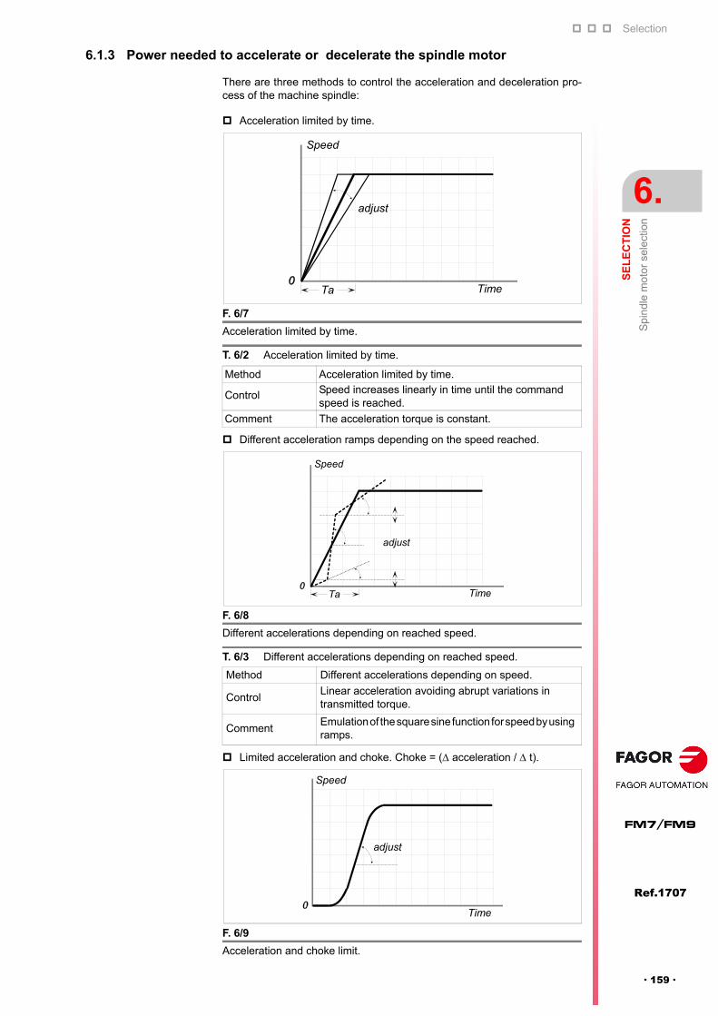
Selection
SE
LE
CT
ION
Spi
ndl
e m
otor
sel
ectio
n
6.
Ref.1707
· 159 ·
FM7/FM9
6.1.3 Power needed to accelerate or decelerate the spindle motor
There are three methods to control the acceleration and deceleration pro-cess of the machine spindle:
Acceleration limited by time.
Different acceleration ramps depending on the speed reached.
Limited acceleration and choke. Choke = ( acceleration / t).
F. 6/7
Acceleration limited by time.
T. 6/2 Acceleration limited by time.
Method Acceleration limited by time.
Control Speed increases linearly in time until the command speed is reached.
Comment The acceleration torque is constant.
F. 6/8
Different accelerations depending on reached speed.
T. 6/3 Different accelerations depending on reached speed.
Method Different accelerations depending on speed.
ControlLinear acceleration avoiding abrupt variations in transmitted torque.
CommentEmulation of the square sine function for speed by using ramps.
F. 6/9
Acceleration and choke limit.
TimeTa
Speed
adjust
adjust
TimeTa
Speed
adjust
Time
Speed
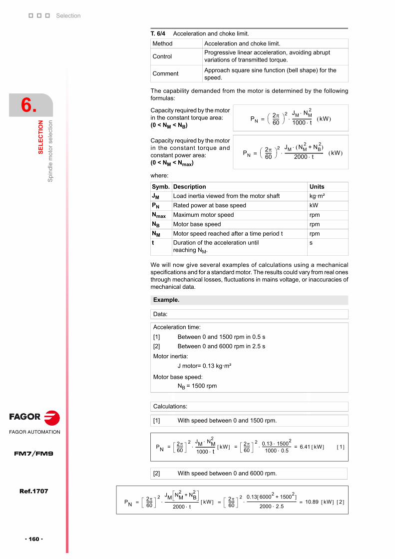
Selection
6.
SE
LE
CT
ION
Spi
ndl
e m
otor
sel
ectio
n
170
Ref.1707
FM7/FM9
· 160 ·
The capability demanded from the motor is determined by the followingformulas:
where:
We will now give several examples of calculations using a mechanicalspecifications and for a standard motor. The results could vary from real onesthrough mechanical losses, fluctuations in mains voltage, or inaccuracies ofmechanical data.
T. 6/4 Acceleration and choke limit.
Method Acceleration and choke limit.
ControlProgressive linear acceleration, avoiding abrupt variations of transmitted torque.
Comment Approach square sine function (bell shape) for the speed.
Capacity required by the motorin the constant torque area: (0 < NM < NB)
Capacity required by the motorin the constant torque andconstant power area: (0 < NM < Nmax)
Symb. Description Units
JM Load inertia viewed from the motor shaft kg·m²
PN Rated power at base speed kW
Nmax Maximum motor speed rpm
NB Motor base speed rpm
NM Motor speed reached after a time period t rpm
t Duration of the acceleration until reaching NM.
s
Example.
Data:
Acceleration time:
[1] Between 0 and 1500 rpm in 0.5 s
[2] Between 0 and 6000 rpm in 2.5 s
Motor inertia:
J motor= 0.13 kg·m²
Motor base speed:
NB = 1500 rpm
Calculations:
[1] With speed between 0 and 1500 rpm.
[2] With speed between 0 and 6000 rpm.
PN260------
2 JM NM2
1000 t-------------------- kW =
PN260------
2 JM NM2
NB2
+
2000 t--------------------------------------- kW =
PN260-------
2 JM NM2
1000 t---------------------- kW 2
60-------
2 0.13 15002
1000 0.5--------------------------------- 6.41 kW 1 = = =
PN260-------
2 JM NM2
NB2
+
2000 t-------------------------------------- kW 2
60-------
2 0.13 60002
15002
+
2000 2.5-------------------------------------------------------- 10.89 kW 2 = = =
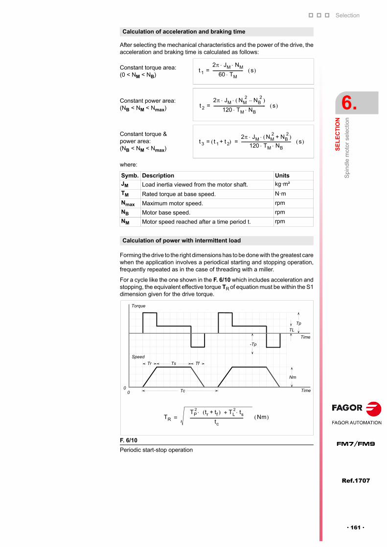
Selection
SE
LE
CT
ION
Spi
ndl
e m
otor
sel
ectio
n
6.
Ref.1707
· 161 ·
FM7/FM9
After selecting the mechanical characteristics and the power of the drive, theacceleration and braking time is calculated as follows:
where:
Forming the drive to the right dimensions has to be done with the greatest carewhen the application involves a periodical starting and stopping operation,frequently repeated as in the case of threading with a miller.
For a cycle like the one shown in the F. 6/10 which includes acceleration andstopping, the equivalent effective torque TR of equation must be within the S1dimension given for the drive torque.
Calculation of acceleration and braking time
Constant torque area: (0 < NM < NB)
Constant power area: (NB < NM < Nmax)
Constant torque & power area: (NB < NM < Nmax)
Symb. Description UnitsJM Load inertia viewed from the motor shaft. kg·m²
TM Rated torque at base speed. N·m
Nmax Maximum motor speed. rpm
NB Motor base speed. rpm
NM Motor speed reached after a time period t. rpm
Calculation of power with intermittent load
F. 6/10
Periodic start-stop operation
t 1
2 J M NM
60 TM------------------------------- s =
t 2
2 J M NM2
NB2–
120 TM NB ----------------------------------------------------- s =
t 3 t 1 t 2+ 2 JM NM
2NB
2+
120 TM NB --------------------------------------------------- s = =
0
Speed
0
Torque
Time
Tc Time
Nm
TL
Tp
-Tp
Tr TfTs
TR
TP2 tr tf+ TL
2 ts+
tc------------------------------------------------------- Nm =

Selection
6.
SE
LE
CT
ION
Te
chni
cal c
har
acte
ristic
s
170
Ref.1707
FM7/FM9
· 162 ·
6.2 Technical characteristics
6.2.1 FM7-XXXX-XXXX-E01/E02 series
T. 6/5 Technical data. Assigning the drive to the corresponding motor model.
Rated torque Rated power Spindle drive
Mn (S1) Pn (S1) Pn (S6-40%) References
N·m kW kW Modular Compact
FM7-A037--E01/E02 23.5 3.7 5.5 SPD 1.25 SCD 1.25A
FM7-A055--E01/E02 35.0 5.5 7.7 SPD 1.25 SCD 1.25A
FM7-A075--E01/E02 47.7 7.5 11.0 SPD 1.35 SCD 2.35
FM7-A090--E01/E02 57.4 9.0 13.0 SPD 2.50 SCD 2.50
FM7-A110--E01/E02 70.0 11.0 15.5 SPD 2.50 SCD 2.50
FM7-A150--E01/E02 95.5 15.0 22.0 SPD 2.75 SCD 2.75
FM7-A185--E01/E02 117.8 18.5 26.0 SPD 2.85 -
FM7-A220--E01/E02 140.0 22.0 33.0 SPD 3.100 -
FM7-B120--E01/E02 114.6 12.0 18.5 SPD 2.75 -
FM7-B170--E01/E02 162.3 17.0 25.0 SPD 2.85 -
FM7-A300--E01 191.0 30.0 45.0 SPD 3.150 -
FM7-B220--E01 210.0 22.0 33.0 SPD 3.100 -
FM7-A370--E01 235.0 37.0 56.0 SPD 3.200 -
FM7-B280--E01 267.4 28.0 42.0 SPD 3.150 -
FM7-A510--E01/E02 325.0 51.0 71.0 SPD 3.200 -
FM7-C215--E01/E02 410.6 21.5 29.0 SPD 3.150 -
FM7-C270--E01/E02 515.7 27.0 37.0 SPD 3.200 -
FM7-E600-CB-E01 458.4 60.0 80.0 SPD 3.200 -
T. 6/6 Technical data.
VbaseRated current
InertiaMax.
speedCurrent without
Rated voltage
Mass
nN In (S1) Jnmax
Io UnP
E01 E02 B/P
1/min A kg·cm² 1/min A V kg
FM7-A037--E01/E02 1500 12.4 140 9000 12000 8.45 288.6 47/49
FM7-A055--E01/E02 1500 14.6 210 9000 10000 7.34 304.1 52/56
FM7-A075--E01/E02 1500 19.8 260 9000 10000 9.47 301.7 59/64
FM7-A090--E01/E02 1500 25.0 330 9000 10000 12.04 282.1 68/73
FM7-A110--E01/E02 1500 28.0 690 9000 10000 13.54 302.9 94/110
FM7-A150--E01/E02 1500 39.4 690 8000 9000 19.51 297.6 94/110
FM7-A185--E01/E02 1000 35.0 890 8000 9000 20.96 286.6 120/130
FM7-A220--E01/E02 1500 47.5 890 8000 9000 24.98 305.0 120/130
FM7-B120--E01/E02 1000 61.4 1080 8000 9000 36.07 291.1 135/145
FM7-B170--E01/E02 1000 47.3 1080 8000 9000 24.92 284.7 135/145
FM7-A300--E01 1500 82.1 2310 6500 - 43.20 279.7 220/230
FM7-B220--E01 1000 64.9 2310 6500 - 35.46 267.3 220/230
FM7-A370--E01 1500 90.0 2660 6500 - 35.26 293.1 250/260
FM7-B280--E01 1000 78.2 2660 6500 - 38.16 269.0 250/260
FM7-A510--E01/E02 1500 115.2 4730 5000 6000 43.83 314.3 340/350
FM7-C215--E01/E02 500 87.9 4730 5000 6000 36.73 190.3 340/350
FM7-C270--E01/E02 500 117.0 5840 5000 6000 48.18 177.5 380/390
FM7-E600-CB-E01 1250 117.4 8720 5000 - 53.49 370.4 525/540
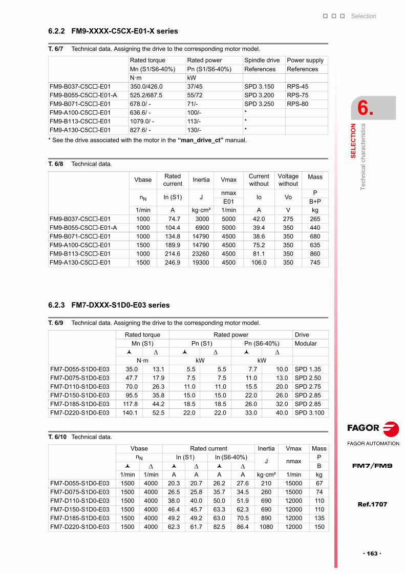
Selection
SE
LE
CT
ION
Te
chni
cal c
har
acte
ristic
s
6.
Ref.1707
· 163 ·
FM7/FM9
6.2.2 FM9-XXXX-C5CX-E01-X series
6.2.3 FM7-DXXX-S1D0-E03 series
T. 6/7 Technical data. Assigning the drive to the corresponding motor model.
Rated torque Rated power Spindle drive Power supply
Mn (S1/S6-40%) Pn (S1/S6-40%) References References
N·m kW
FM9-B037-C5C-E01 350.0/426.0 37/45 SPD 3.150 RPS-45
FM9-B055-C5C-E01-A 525.2/687.5 55/72 SPD 3.200 RPS-75
FM9-B071-C5C-E01 678.0/ - 71/- SPD 3.250 RPS-80
FM9-A100-C5C-E01 636.6/ - 100/- *
FM9-B113-C5C-E01 1079.0/ - 113/- *
FM9-A130-C5C-E01 827.6/ - 130/- *
* See the drive associated with the motor in the “man_drive_ct” manual.
T. 6/8 Technical data.
VbaseRated current
Inertia VmaxCurrent without
Voltage without
Mass
nN In (S1) Jnmax
Io VoP
E01 B+P1/min A kg·cm² 1/min A V kg
FM9-B037-C5C-E01 1000 74.7 3000 5000 42.0 275 265
FM9-B055-C5C-E01-A 1000 104.4 6900 5000 39.4 350 440
FM9-B071-C5C-E01 1000 134.8 14790 4500 38.6 350 680
FM9-A100-C5C-E01 1500 189.9 14790 4500 75.2 350 635
FM9-B113-C5C-E01 1000 214.6 23260 4500 81.1 350 860
FM9-A130-C5C-E01 1500 246.9 19300 4500 106.0 350 745
T. 6/9 Technical data. Assigning the drive to the corresponding motor model.
Rated torque Rated power Drive
Mn (S1) Pn (S1) Pn (S6-40%) Modular
N·m kW kW
FM7-D055-S1D0-E03 35.0 13.1 5.5 5.5 7.7 10.0 SPD 1.35
FM7-D075-S1D0-E03 47.7 17.9 7.5 7.5 11.0 13.0 SPD 2.50
FM7-D110-S1D0-E03 70.0 26.3 11.0 11.0 15.5 20.0 SPD 2.75
FM7-D150-S1D0-E03 95.5 35.8 15.0 15.0 22.0 26.0 SPD 2.85
FM7-D185-S1D0-E03 117.8 44.2 18.5 18.5 26.0 32.0 SPD 2.85
FM7-D220-S1D0-E03 140.1 52.5 22.0 22.0 33.0 40.0 SPD 3.100
T. 6/10 Technical data.
Vbase Rated current Inertia Vmax MassnN In (S1) In (S6-40%)
J nmaxP
B
1/min 1/min A A A A kg·cm² 1/min kg
FM7-D055-S1D0-E03 1500 4000 20.3 20.7 26.2 27.6 210 15000 67
FM7-D075-S1D0-E03 1500 4000 26.5 25.8 35.7 34.5 260 15000 74
FM7-D110-S1D0-E03 1500 4000 38.0 40.0 50.0 51.9 690 12000 110
FM7-D150-S1D0-E03 1500 4000 46.4 45.7 63.3 62.3 690 12000 110
FM7-D185-S1D0-E03 1500 4000 49.2 49.2 63.0 70.5 890 12000 135
FM7-D220-S1D0-E03 1500 4000 62.3 61.7 82.5 86.4 1080 12000 150
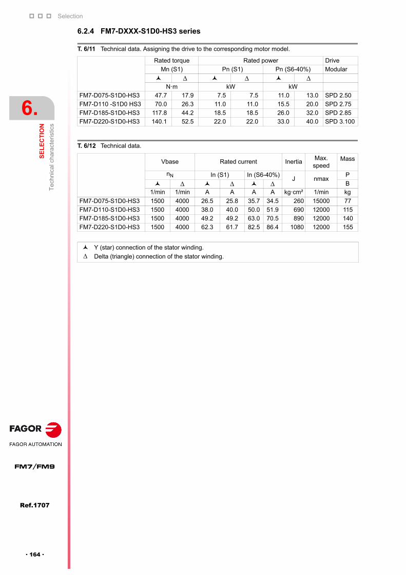
Selection
6.
SE
LE
CT
ION
Te
chni
cal c
har
acte
ristic
s
170
Ref.1707
FM7/FM9
· 164 ·
6.2.4 FM7-DXXX-S1D0-HS3 series
T. 6/11 Technical data. Assigning the drive to the corresponding motor model.
Rated torque Rated power Drive
Mn (S1) Pn (S1) Pn (S6-40%) Modular
N·m kW kW
FM7-D075-S1D0-HS3 47.7 17.9 7.5 7.5 11.0 13.0 SPD 2.50
FM7-D110 -S1D0 HS3 70.0 26.3 11.0 11.0 15.5 20.0 SPD 2.75
FM7-D185-S1D0-HS3 117.8 44.2 18.5 18.5 26.0 32.0 SPD 2.85
FM7-D220-S1D0-HS3 140.1 52.5 22.0 22.0 33.0 40.0 SPD 3.100
T. 6/12 Technical data.
Vbase Rated current InertiaMax.
speedMass
nN In (S1) In (S6-40%)J nmax
P
B1/min 1/min A A A A kg·cm² 1/min kg
FM7-D075-S1D0-HS3 1500 4000 26.5 25.8 35.7 34.5 260 15000 77
FM7-D110-S1D0-HS3 1500 4000 38.0 40.0 50.0 51.9 690 12000 115
FM7-D185-S1D0-HS3 1500 4000 49.2 49.2 63.0 70.5 890 12000 140
FM7-D220-S1D0-HS3 1500 4000 62.3 61.7 82.5 86.4 1080 12000 155
Y (star) connection of the stator winding.
Delta (triangle) connection of the stator winding.

Selection
SE
LE
CT
ION
Spi
ndle
driv
e se
lect
ion
6.
Ref.1707
· 165 ·
FM7/FM9
6.3 Spindle drive selectionOnce the necessary motor model has been selected following the selection criteria, one must determinethe reference of the modular spindle drive SPD associated with the motor. Check the technicalcharacteristics table of the motor, given in the previous section that shows the drive associated with themotor in its last columns for modular SPD drives and for compact SCD drives.
The data to be checked when selecting a modular SPD drive for FM7 motor series (E01, E02, E03 andHS3) or FM9 motor series (E01) are:
The value 0.7 x In (S1) of the drive must be higher than or equal to the magnetizing current (or withoutload) of the motor.
The current In (S1) of the drive must be higher than or equal to the rated current of the motor.
The current I (S6-40%) of the drive must be higher than or equal to the current I (S6-40%) of the motor.
The Imax current supplied by the drive must be enough for the spindle to accelerate to its maximumwork speed in the required amount of time.
Note that, with FM9 motors larger than the B055:
the «FM9 motor + associated drive» combination is designed to work in duty cycle S1.
a torque overload at high speed is allowed depending on the maximum current allowed for thecombination (power supply+drive). To estimate its value, use the smallest rated power of the drive andthat of the power supplied minus 7 %.
Also keep in mind that, with FM9 motors larger than the B037, the DC BUS must be configured at 675 VDC (for RPS power supplies) in order to obtain the graph of rated power at high speed.
NOTE. This condition may not be required depending on the application.
T. 6/13 Technical data. FM7. E01/E02 series.
Motor Current (A) Drive Current (A)
Io In (S1) IS6-40% Ref. 0.7x In In (S1) IS6-40%
FM7-A037--E01/E02 8.45 12.4 15.8 SPD 1.25 11.2 16.0 20.8
FM7-A055--E01/E02 7.34 14.6 18.9 SPD 1.25 11.2 16.0 20.8
FM7-A075--E01/E02 9.47 19.8 27.0 SPD 1.35 16.2 23.1 30.0
FM7-A090--E01/E02 12.04 25.1 33.6 SPD 2.50 21.7 31.0 40.3
FM7-A110--E01/E02 13.54 27.9 36.5 SPD 2.50 21.7 31.0 40.3
FM7-A150--E01/E02 19.51 39.3 52.8 SPD 2.75 29.0 42.0 54.6
FM7-A185--E01/E02 24.98 47.4 61.5 SPD 2.85 35.0 50.0 65.0
FM7-A220--E01/E02 36.07 61.4 81.3 SPD 3.100 49.0 70.0 91.0
FM7-B120--E01/E02 20.96 35.0 47.5 SPD 2.75 29.0 42.0 54.6
FM7-B170--E01/E02 24.92 47.2 64.1 SPD 2.85 35.0 50.0 65.0
FM7-A300--E01 43.20 82.1 113.2 SPD 3.150 63.0 90.0 117.0
FM7-B220--E01 35.46 64.9 89.5 SPD 3.100 49.0 70.0 91.0
FM7-A370--E01 35.26 89.9 127.9 SPD 3.200 84.7 121.0 157.3
FM7-B280--E01 38.16 78.2 109.0 SPD 3.150 63.0 90.0 117.0
FM7-A510--E01/E02 43.83 115.1 153.2 SPD 3.200 84.7 121.0 157.3
FM7-C215--E01/E02 36.73 87.8 114.7 SPD 3.150 63.0 90.0 117.0
FM7-C270--E01/E02 48.18 116.9 153.2 SPD 3.200 84.7 121.0 157.3
FM7-E600-C-E01 53.49 117.4 150.4 SPD 3.200 84.7 121.0 157.3
NOTE. In many applications, it is possible to associate the FM7-A370--E01 motor with an SPD3.150 drive.
T. 6/14 Technical data. FM9. E01 series. Y (star) connection.
Motor Current (A) Drive Power supply
Current (A)
Io In (S1) IS6-40% Ref. Ref. 0.7xIn In (S1) IS6-40%
FM9-B037-C5C-E01 42.0 74.7 89.7 SPD 3.150 RPS-45 63.0 90.0 117.0
FM9-B055-C5C-E01-A 39.4 104.4 146.2 SPD 3.200 RPS-75 84.7 121.0 157.3
FM9-B071-C5C-E01 38.6 134.8 - SPD 3.250 RPS-80 94.5 135.0 *FM9-A100-C5C-E01 75.2 189.9 - * * * * *FM9-B113-C5C-E01 81.1 214.6 - * * * * *FM9-A130-C5C-E01 106.0 246.9 - * * * * ** See the drive associated with the motor in the “man_drive_ct” manual.
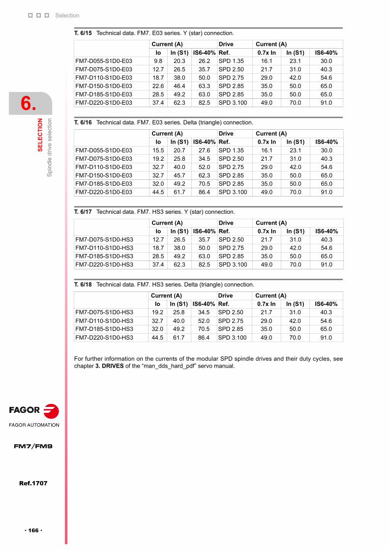
Selection
6.
SE
LE
CT
ION
Spi
ndle
driv
e se
lect
ion
170
Ref.1707
FM7/FM9
· 166 ·
For further information on the currents of the modular SPD spindle drives and their duty cycles, seechapter 3. DRIVES of the “man_dds_hard_pdf” servo manual.
T. 6/15 Technical data. FM7. E03 series. Y (star) connection.
Current (A) Drive Current (A)
Io In (S1) IS6-40% Ref. 0.7x In In (S1) IS6-40%
FM7-D055-S1D0-E03 9.8 20.3 26.2 SPD 1.35 16.1 23.1 30.0
FM7-D075-S1D0-E03 12.7 26.5 35.7 SPD 2.50 21.7 31.0 40.3
FM7-D110-S1D0-E03 18.7 38.0 50.0 SPD 2.75 29.0 42.0 54.6
FM7-D150-S1D0-E03 22.6 46.4 63.3 SPD 2.85 35.0 50.0 65.0
FM7-D185-S1D0-E03 28.5 49.2 63.0 SPD 2.85 35.0 50.0 65.0
FM7-D220-S1D0-E03 37.4 62.3 82.5 SPD 3.100 49.0 70.0 91.0
T. 6/16 Technical data. FM7. E03 series. Delta (triangle) connection.
Current (A) Drive Current (A)
Io In (S1) IS6-40% Ref. 0.7x In In (S1) IS6-40%
FM7-D055-S1D0-E03 15.5 20.7 27.6 SPD 1.35 16.1 23.1 30.0
FM7-D075-S1D0-E03 19.2 25.8 34.5 SPD 2.50 21.7 31.0 40.3
FM7-D110-S1D0-E03 32.7 40.0 52.0 SPD 2.75 29.0 42.0 54.6
FM7-D150-S1D0-E03 32.7 45.7 62.3 SPD 2.85 35.0 50.0 65.0
FM7-D185-S1D0-E03 32.0 49.2 70.5 SPD 2.85 35.0 50.0 65.0
FM7-D220-S1D0-E03 44.5 61.7 86.4 SPD 3.100 49.0 70.0 91.0
T. 6/17 Technical data. FM7. HS3 series. Y (star) connection.
Current (A) Drive Current (A)
Io In (S1) IS6-40% Ref. 0.7x In In (S1) IS6-40%
FM7-D075-S1D0-HS3 12.7 26.5 35.7 SPD 2.50 21.7 31.0 40.3
FM7-D110-S1D0-HS3 18.7 38.0 50.0 SPD 2.75 29.0 42.0 54.6
FM7-D185-S1D0-HS3 28.5 49.2 63.0 SPD 2.85 35.0 50.0 65.0
FM7-D220-S1D0-HS3 37.4 62.3 82.5 SPD 3.100 49.0 70.0 91.0
T. 6/18 Technical data. FM7. HS3 series. Delta (triangle) connection.
Current (A) Drive Current (A)
Io In (S1) IS6-40% Ref. 0.7x In In (S1) IS6-40%
FM7-D075-S1D0-HS3 19.2 25.8 34.5 SPD 2.50 21.7 31.0 40.3
FM7-D110-S1D0-HS3 32.7 40.0 52.0 SPD 2.75 29.0 42.0 54.6FM7-D185-S1D0-HS3 32.0 49.2 70.5 SPD 2.85 35.0 50.0 65.0
FM7-D220-S1D0-HS3 44.5 61.7 86.4 SPD 3.100 49.0 70.0 91.0
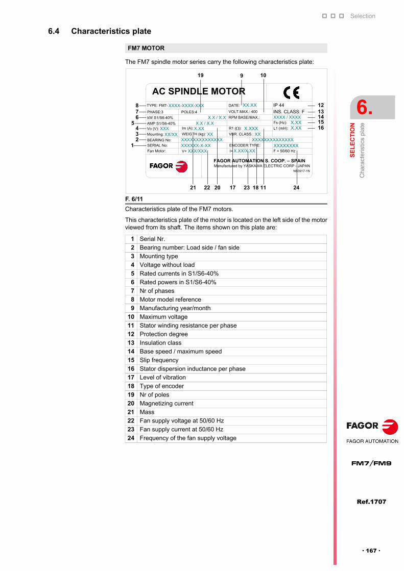
Selection
SE
LE
CT
ION
Cha
ract
eris
tics
plat
e
6.
Ref.1707
· 167 ·
FM7/FM9
6.4 Characteristics plate
The FM7 spindle motor series carry the following characteristics plate:
This characteristics plate of the motor is located on the left side of the motorviewed from its shaft. The items shown on this plate are:
FM7 MOTOR
F. 6/11
Characteristics plate of the FM7 motors.
1 Serial Nr.
2 Bearing number: Load side / fan side
3 Mounting type
4 Voltage without load
5 Rated currents in S1/S6-40%
6 Rated powers in S1/S6-40%
7 Nr of phases
8 Motor model reference
9 Manufacturing year/month
10 Maximum voltage
11 Stator winding resistance per phase
12 Protection degree
13 Insulation class
14 Base speed / maximum speed
15 Slip frequency
16 Stator dispersion inductance per phase
17 Level of vibration
18 Type of encoder
19 Nr of poles
20 Magnetizing current
21 Mass
22 Fan supply voltage at 50/60 Hz
23 Fan supply current at 50/60 Hz
24 Frequency of the fan supply voltage
AC SPINDLE MOTOR
Fs (Hz):
FAGOR AUTOMATION S. COOP. – SPAIN
XX.XX
X.XXXXXXX
X.XX X.XXX.XX
X.X / X.X
IP 44 XXXX-XXXX-XXX
XXXXX/XX
INS. CLASS: F VOLT.MAX.: 400
DATE:TYPE: FM7-
PHASE:3
kW S1/S6-40%
POLES:4
Manufactured by YASKAWA ELECTRIC CORP - JAPANNB3917-1N
AMP S1/S6-40% X.X / X.XVo (V):
Mounting:
BEARING No:SERIAL No:
XXXXXXXXXXXXXX XXXXXXXXXXXXXX
Im (A):
WEIGTH (kg):
R1 ( ): L1 (mH):
VBR. CLASS.:
Fan Motor: V= XXX/XXXENCODER TYPE: XXXXXXXXXXXXXX-X-XXI= X.XX/X.XX F = 50/60 Hz
RPM BASE/MAX.: XXXX / XXXX
1234
5678
9 10
11
1213141516
17 18
19
2021 22 23 24
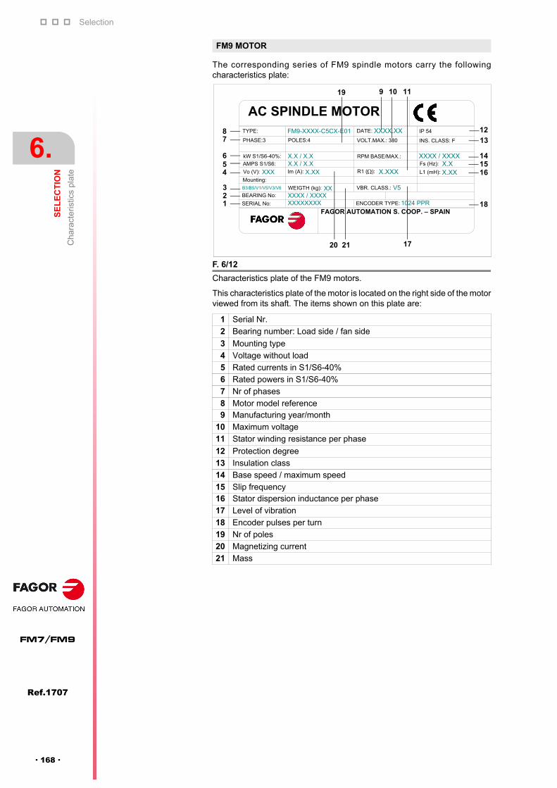
Selection
6.
SE
LE
CT
ION
Cha
ract
eris
tics
plat
e
170
Ref.1707
FM7/FM9
· 168 ·
The corresponding series of FM9 spindle motors carry the followingcharacteristics plate:
This characteristics plate of the motor is located on the right side of the motorviewed from its shaft. The items shown on this plate are:
FM9 MOTOR
F. 6/12
Characteristics plate of the FM9 motors.
1 Serial Nr.
2 Bearing number: Load side / fan side
3 Mounting type
4 Voltage without load
5 Rated currents in S1/S6-40%
6 Rated powers in S1/S6-40%
7 Nr of phases
8 Motor model reference9 Manufacturing year/month
10 Maximum voltage
11 Stator winding resistance per phase
12 Protection degree
13 Insulation class
14 Base speed / maximum speed
15 Slip frequency16 Stator dispersion inductance per phase
17 Level of vibration
18 Encoder pulses per turn
19 Nr of poles
20 Magnetizing current
21 Mass
AC SPINDLE MOTOR
FAGOR AUTOMATION S. COOP. – SPAIN
XXXX.XX
V5XX
X.XX
XXXX / XXXX1024 PPRXXXXXXXX
X.XXX.X
XXXX / XXXXX.X / X.XX.X / X.X
FM9-XXXX-C5CX-E01
XXX
B3/B5/V1/V5/V3/V6
TYPE:
PHASE:3
kW S1/S6-40%:
AMPS S1/S6:
Mounting:
BEARING No:
SERIAL No:
Vo (V):
POLES:4
Im (A):
WEIGTH (kg):
ENCODER TYPE:
VBR. CLASS.:
X.XXXR1 ( ): L1 (mH):
Fs (Hz): RPM BASE/MAX.:
INS. CLASS: F
IP 54 DATE:
VOLT.MAX.: 380
3
4
21
56
78
9 10 11
12
13
141516
18
19
20 21 17

Selection
SE
LE
CT
ION
Sal
es r
efer
ence
6.
Ref.1707
· 169 ·
FM7/FM9
6.5 Sales reference
The sales reference of each motor model is determined in a set of blocksshowing letters and numbers whose meaning is:
FM7 MOTOR
F. 6/13
FM7 motor model name. E01/E02 series.
NOTE 1. The “flange+foot” mount type comes in all models except A037,A055, A075 and A090. NOTE 2. Models A300, A370, B220, B280 and E600are not available for the E02 series. NOTE 3. E600 models can only havethe C axis option for feedback and V10 vibration degree.
F. 6/14
FM7 motor model name. Series E03/HS3.
NOTE. The D055 and D150 models will not be available in the HS3 series.
BASE SPEED (Single winding)
FAGOR M7 MOTOR
1500 rev/min
AB
FM7- - - E0
500 rev/min1000 rev/min
C
MOTOR POWER kW (Duty S1). Note. The kW for each model are obtained by multiplying the given value by 0.1. E.g. An FM7- B280 motor can provide up to 28 kW in S1.
A 037, 055, 075, 090, 110, 150, 185, 220, 300, 370, 510
B 120, 170, 220, 280
C 215, 270
FEEDBACK Standard encoder S
CC axis encoder
MOUNTING Flange 1
3Foot
5Flange + Foot
DEGREE OF VIBRATION
V10 B
CV5
DV3
SHAFT Keyless 01With key (half-key balancing)
RELEASE 1
2
E01 series
E02 series
1250 rev/min E
E 600
(see note 1)
(see note 3)
(see note 3)
(see note 2)
BASE SPEED(option to configure winding connection)
FAGOR M7 MOTOR
D
FM7- - - 3
MOTOR POWER kW (Duty S1). Note. The kW for each model are obtained by multiplying the given value by 0.1. E. g. An FM7- D150 motor canprovide up to 15 kW in S1.
D 055, 075, 110, 150, 185, 220
FEEDBACK Magnetic TTL encoder S
RELEASE E0
HS
E03 series
HS3 series (hollow shaft)
1500 rev/min for a star (Y) connection
1000 rev/min for a triangle () connection
MOUNTING Flange 1
DEGREE OFVIBRATION
V3 D
SHAFT Keyless 0
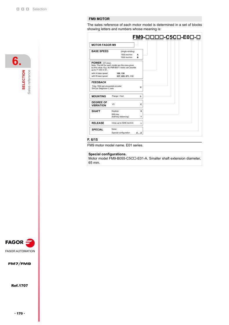
Selection
6.
SE
LE
CT
ION
Sal
es r
efer
ence
170
Ref.1707
FM7/FM9
· 170 ·
The sales reference of each motor model is determined in a set of blocksshowing letters and numbers whose meaning is:
FM9 MOTOR
F. 6/15
FM9 motor model name. E01 series.
Special configurations. Motor model FM9-B055-C5C-E01-A. Smaller shaft extension diameter,65 mm.
BASE SPEED (single winding)
MOTOR FAGOR M9
1500 rev/min AB
FM9--C5C-E0-
1000 rev/min
POWER (S1 duty). Note. The kW for each model are the ones given by this value. E.g. An FM9-B071 motor can provide up to 71 kW in S1.
with A base speed 100, 130with B base speed 037, 055, 071, 113
FEEDBACK
C1Vpp 1024 ppt sinusoidal encoder SinCos Stegmann C axis
MOUNTING 5Flange + foot
DEGREE OF VIBRATION CV5
SHAFT Keyless 0
1With key(half-key balancing)
RELEASE 1nmax up to 5000 rev/min
SPECIAL None
Special configuration A ... Z


Fagor Automation S. Coop.
Bº San Andrés, 19 - Apdo. 144E-20500 Arrasate-Mondragón, SpainTel: +34 943 719 200
+34 943 039 800Fax: +34 943 791 712E-mail: [email protected]
FAGOR AUTOMATION


![Fm7-15[1] the Army Universal Task List](https://img.pdfslide.us/doc/110x75/577cd1401a28ab9e7893fa02/fm7-151-the-army-universal-task-list.jpg)