Embed Size (px)
Citation preview
FM200®
MODEL FTFIRE EXTINGUISHERS
INSTALLATION INSTRUCTIONSOWNER’S MANUAL
THIS MANUAL IS AN INTEGRAL PART OF THE SYSTEM AND AS SUCH, THEEXTINGUISHER MUST BE INSTALLED AND MAINTAINED ACCORDINGLY.
READ AND COMPLY WITH THESE INSTRUCTIONS, WARNINGSAND LIMITATIONS BEFORE INSTALLING.
SUITABLE FOR USEFT MODELS: 32°F – 130°F ( 0°C – 54°C)
ALWAYS MAINTAIN THIS OWNER’S MANUAL NEARBYFOR OPERATOR REFERENCE.
APPROVALSFACTORY MUTUAL - FM # 3022058
U.S. COAST GUARD - U.S.C.G. # 162.029/241
REV. A PRINTED IN USA PART NO. 123-186
WARNING
CONCENTRATED AGENT AND BY-PRODUCT OF APPLICATION TO FIRE ARE TOXIC.AVOID BREATHING OF FUMES OR PROLONGED EXPOSURE. ACCIDENTAL DIS-CHARGE MAY OCCUR DURING HANDLING OR INSTALLATION OF THIS DEVICE, READAND COMPLY WITH INSTRUCTIONS, WARNINGS, AND LIMITATIONS CONTAINED INTHIS MANUAL. DO NOT LIFT, CARRY, OR HANDLE BY VALVE. DO NOT DROP. KEEPAWAY FROM HEAT. KEEP AWAY FROM CHILDREN.
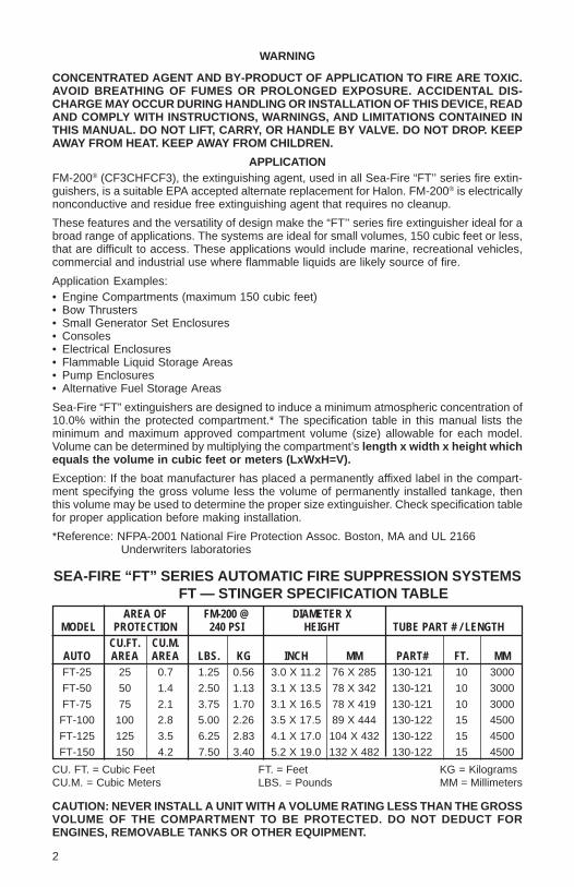
APPLICATIONFM-200® (CF3CHFCF3), the extinguishing agent, used in all Sea-Fire “FT’’ series fire extin-guishers, is a suitable EPA accepted alternate replacement for Halon. FM-200® is electricallynonconductive and residue free extinguishing agent that requires no cleanup.
These features and the versatility of design make the “FT’’ series fire extinguisher ideal for abroad range of applications. The systems are ideal for small volumes, 150 cubic feet or less,that are difficult to access. These applications would include marine, recreational vehicles,commercial and industrial use where flammable liquids are likely source of fire.
Application Examples:• Engine Compartments (maximum 150 cubic feet)• Bow Thrusters• Small Generator Set Enclosures• Consoles• Electrical Enclosures• Flammable Liquid Storage Areas• Pump Enclosures• Alternative Fuel Storage Areas
Sea-Fire “FT” extinguishers are designed to induce a minimum atmospheric concentration of10.0% within the protected compartment.* The specification table in this manual lists theminimum and maximum approved compartment volume (size) allowable for each model.Volume can be determined by multiplying the compartment’s length x width x height whichequals the volume in cubic feet or meters (LxWxH=V).
Exception: If the boat manufacturer has placed a permanently affixed label in the compart-ment specifying the gross volume less the volume of permanently installed tankage, thenthis volume may be used to determine the proper size extinguisher. Check specification tablefor proper application before making installation.
*Reference: NFPA-2001 National Fire Protection Assoc. Boston, MA and UL 2166Underwriters laboratories
SEA-FIRE “FT” SERIES AUTOMATIC FIRE SUPPRESSION SYSTEMSFT — STINGER SPECIFICATION TABLE
AREA OF FM-200 @ DIAMETER XMODEL PROTECTION 240 PSI HEIGHT TUBE PART # / LENGTH
CU.FT. CU.M.AUTO AREA AREA LBS. KG INCH MM PART# FT. MMFT-25 25 0.7 1.25 0.56 3.0 X 11.2 76 X 285 130-121 10 3000
FT-50 50 1.4 2.50 1.13 3.1 X 13.5 78 X 342 130-121 10 3000
FT-75 75 2.1 3.75 1.70 3.1 X 16.5 78 X 419 130-121 10 3000
FT-100 100 2.8 5.00 2.26 3.5 X 17.5 89 X 444 130-122 15 4500
FT-125 125 3.5 6.25 2.83 4.1 X 17.0 104 X 432 130-122 15 4500
FT-150 150 4.2 7.50 3.40 5.2 X 19.0 132 X 482 130-122 15 4500
CU. FT. = Cubic Feet FT. = Feet KG = KilogramsCU.M. = Cubic Meters LBS. = Pounds MM = Millimeters
CAUTION: NEVER INSTALL A UNIT WITH A VOLUME RATING LESS THAN THE GROSSVOLUME OF THE COMPARTMENT TO BE PROTECTED. DO NOT DEDUCT FORENGINES, REMOVABLE TANKS OR OTHER EQUIPMENT.
2
REMINDER: Sea-Fire systems shall be considered as supplementary to the number of portablefire extinguishers required on-board and are designed and intended for enclosed unoccupiedcompartment installations that are not subject to direct weather or water.
SYSTEM OPERATIONS
Sea-Fire units described in this manual are automatically actuated by a heat actuated tube.Discharge will occur as a result of direct flame impingement. The Sea-Fire FT system usesthe supplied length of temperature sensitive tubing as both detection and delivery system.The tubing should be routed close to the hazard, where fire is likely to occur, but away fromheat sources that could accidentally cause it to operate. Upon flame impingement, the tubingwill rupture, and the extinguishing agent will discharge through the rupture point. No separatedischarge nozzle is needed.
CAUTION: IN CASE OF EXTINGUISHER DISCHARGE, DO NOT RUSH TO OPEN THEPROTECTED COMPARTMENT. LET THE EXTINGUISHING AGENT WORK FOR SEVERALMINUTES. HAVE A PORTABLE EXTINGUISHER AVAILABLE AND USE CARE WHENOPENING THE COMPARTMENT.
AVOID BREATHING FIRE RELATED FUMES OR VAPOR.
NOTE: It is important to retain the designed vapor concentration within the compartment toinsure complete fire outage. Upon discharge, all powered ventilation (blowers) must be shutdown.
PRESSURE SWITCH
Sea-Fire “FT” series extinguishers are equipped with a factory installed pressure switch whichis intended for cylinder pressure supervision and may also be used to control other electricalfunctions (engine shutdown, air exchange equipment, electric supply, etc.)
When using the pressure switch as an electrical disconnect for any equipment shutdownfunction, a means of overriding (bypassing, shunting) the pressure switch must be providedin order to return the affected equipment to an operational mode after extinguisher dischargehas occurred. The pressure switch is a single pole single throw (SPST) type that is normallyclosed (NC) with the system in the charged condition. Discharge or loss of system pressurewill release the contacts to an open state thereby cutting off any electrical current flow.
NEVER USE PRESSURE SWITCH FOR ELECTRICAL LOADS OVER RATED CAPACITY.
SWITCH SPECIFICATIONS
4.0 AMPS AT 12 VDC 2.0 AMPS AT 28 VDC
For applications requiring larger load capacities, see OPTIONAL EQUIPMENT section INTHIS manual or contact factory.
DIESEL ENGINES
Continued operation of diesel engine(s) and or powered ventilation units will deplete theextinguishing agent and may cause a fire re-flash. Diesel engine(s) must be automaticallyshutdown upon extinguisher discharge.
Note: Power ventilation (blowers) that exceeds one air change per minute within the protectedcompartment must be automatically shutdown upon extinguisher discharge.*
*ABYC requirement - Standard A-4
GASOLINE ENGINES
WARNING: GASOLINE ENGINES AND FANS SHOULD BE AUTOMATICALLY ORMANUALLY SHUT DOWN AT TIME OF DISCHARGE.
Shutdown may be accomplished by interruption of the electrical circuit between the ignitionswitch and the engine coils.
NOTE: Sea-Fire optional engine interrupt systems will automatically shut down engines andpowered ventilation upon discharge of the fire SUPPRESSION system. They are available in12 and 24-volt models with 3, 5 or 8 control circuits, refer to OPTIONAL EQUIPMENT sectionin this manual.
3
OTHER APPLICATIONS
• Engine Compartments (maximum 150 cubic feet)• Bow Thrusters• Small Generator Set Enclosures• Consoles• Electrical Enclosures• Flammable Liquid Storage Areas• Pump Enclosures• Alternative Fuel Storage Areas
In case of a fire and system discharged, the electrical supply to the motor must be discon-nected. Failure to do so may result in re-ignition after the FM-200® concentration depletes.
Disconnect may be accomplished by using a shutdown system. See OPTIONAL EQUIPMENT.
INSTALLATION
READ ENTIRE INSTRUCTION MANUAL AND CYLINDER NAMEPLATE PRIOR TOINSTALLATION.
These installation instructions are intended to cover most normal installations. Additionaltechnical or application information can be obtained by contacting
Sea-Fire Marine Sea-Fire Europe LTDBaltimore, Maryland, USA or Southampton, EnglandTel: 410-687-5500 Tel: (0) 1329 847225
Website: www.sea-fire.com
CAUTION:1. DO NOT INSTALL IN AN AREA DESIGNATED FOR OCCUPANCY.2. ACCIDENTAL DISCHARGE MAY CAUSE SERIOUS INJURY.3. HANDLE THE CYLINDER WITH EXTREME CARE.4. WEAR EYE PROTECTION.5. DO NOT LIFT OR CARRY CYLINDER BY THE MANIFOLD OR ACTUATOR COMPO-
NENTS.6. DO NOT ATTEMPT TO LOOSEN OR REMOVE ANY EXTINGUISHER COMPONENT.7. DO NOT ATTACH SEA-FIRE EXTINGUISHER ON UNDERSIDE OF COVER OR COM-
PARTMENT HATCH THAT COULD BE THROWN CLEAR DUE TO POSSIBLE EX-PLOSION.
8. DO NOT MOUNT WHERE AN ACCUMULATION OF STANDING WATER COULDBLOCK SENSOR OR CAUSE CORROSION.
9. EXTINGUISHER TO BE MOUNTED IN THE VERTICAL POSITION ONLY.10. DO NOT USE FOR PRIMARY ENGINE COMPARTMENT PROTECTION.
EXTINGUISHER INSTALLATION:
Step 1 Carefully remove extinguisher from carton and visually check for damage in shipment.Step 2 To ensure that the extinguisher is operational, both the weight and pressure indicator
must conform with the extinguisher specification as shown on the nameplate. Weighextinguisher (less bracket) on an accurate calibrated scale before installing. Recorddate and weight on tag provided for this purpose.
Step 3 Choose a suitable location inside or outside the protected area where accidentaldamage is unlikely to occur.
Step 4 Ensure mounting surface is durable (Prefer no less than __ inch. Mounting on fiber-glass surfaces: A backing washer (flat) or plate should be utilized if the thickness isless than inch.
Step 5 Using the bracket as a template, drill (4) ____” diameter holes. Mount the bracketusing no less than Grade 5 corrosive resistant ____” fasteners. (See Figure 5)
Step 6 Install the extinguisher into the bracket and latch clamp.Step 7 If required to route detection tube through a compartment wall, drill hole 25/64" diam-
eter, and utilize supplied grommet to protect tube from wear. (See Figure 6)
4
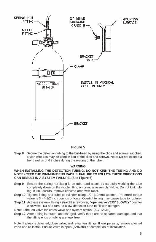
Figure 5
Step 8 Secure the detection tubing to the bulkhead by using the clips and screws supplied.Nylon wire ties may be used in lieu of the clips and screws. Note: Do not exceed abend radius of 6 inches during the routing of the tube.
WARNINGWHEN INSTALLING THE DETECTION TUBING, DO NOT KINK THE TUBING AND DONOT EXCEED THE MINIMUM BEND RADIUS. FAILURE TO FOLLOW THESE DIRECTIONSCAN RESULT IN A SYSTEM FAILURE. (See Figure 6)
Step 9 Ensure the spring nut fitting is on tube, and attach by carefully working the tubecompletely down on the nipple fitting on cylinder assembly/ (Note: Do not kink tub-ing, if kink occurs, remove effected area with razor.
Step 10 Tighten fitting and tube to cylinder using 1/2" (12mm) wrench. Preferred torquevalue is 3 - 4-1/2 inch pounds of force. Overtightening may cause tube to rupture.
Step 11 Activate system - Using a straight screwdriver, “open valve VERY SLOWLY” counterclockwise, 1/4 of a turn, to allow detection tube to fill with nitrogen.
Note: Label on valve indicates valve and system status. (ACTIVATE)Step 12 After tubing is routed, and charged, verify there are no apparent damage, and that
the fitting ends of tubing are leak free.
Note: If a leak is detected, close valve, and re-tighten fittings. If leak persists, remove affectedzone and re-install. Ensure valve is open (Activate) at completion of installation.
5
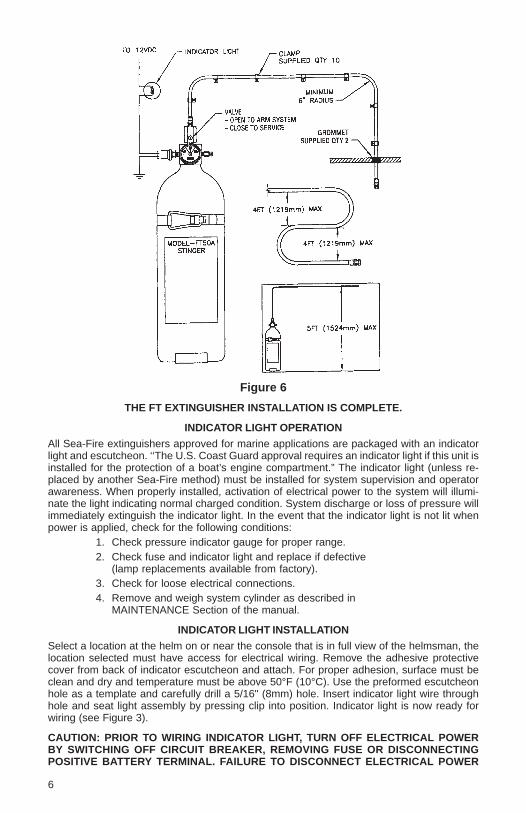
Figure 6
THE FT EXTINGUISHER INSTALLATION IS COMPLETE.
INDICATOR LIGHT OPERATION
All Sea-Fire extinguishers approved for marine applications are packaged with an indicatorlight and escutcheon. ‘‘The U.S. Coast Guard approval requires an indicator light if this unit isinstalled for the protection of a boat’s engine compartment.” The indicator light (unless re-placed by another Sea-Fire method) must be installed for system supervision and operatorawareness. When properly installed, activation of electrical power to the system will illumi-nate the light indicating normal charged condition. System discharge or loss of pressure willimmediately extinguish the indicator light. In the event that the indicator light is not lit whenpower is applied, check for the following conditions:
1. Check pressure indicator gauge for proper range.2. Check fuse and indicator light and replace if defective
(lamp replacements available from factory).3. Check for loose electrical connections.4. Remove and weigh system cylinder as described in
MAINTENANCE Section of the manual.
INDICATOR LIGHT INSTALLATION
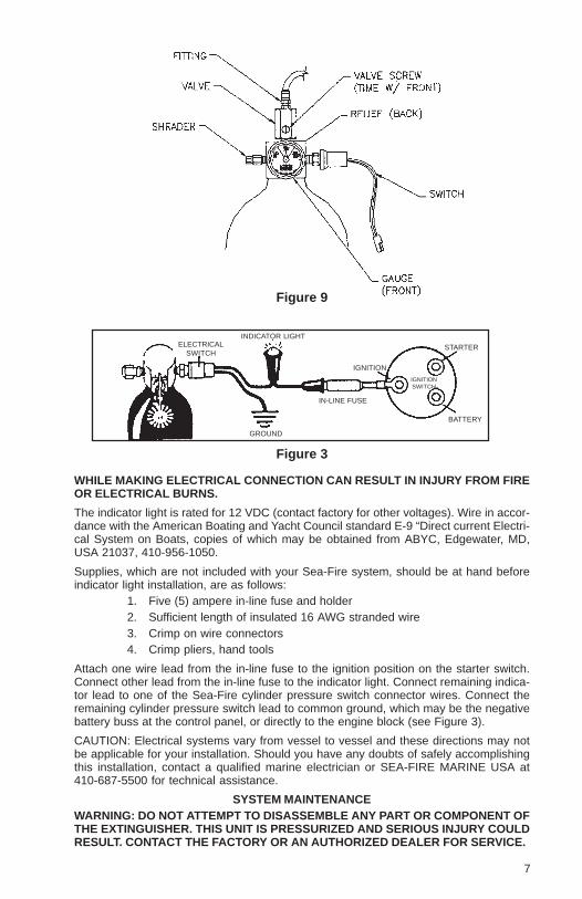
Select a location at the helm on or near the console that is in full view of the helmsman, thelocation selected must have access for electrical wiring. Remove the adhesive protectivecover from back of indicator escutcheon and attach. For proper adhesion, surface must beclean and dry and temperature must be above 50°F (10°C). Use the preformed escutcheonhole as a template and carefully drill a 5/16" (8mm) hole. Insert indicator light wire throughhole and seat light assembly by pressing clip into position. Indicator light is now ready forwiring (see Figure 3).
CAUTION: PRIOR TO WIRING INDICATOR LIGHT, TURN OFF ELECTRICAL POWERBY SWITCHING OFF CIRCUIT BREAKER, REMOVING FUSE OR DISCONNECTINGPOSITIVE BATTERY TERMINAL. FAILURE TO DISCONNECT ELECTRICAL POWER
6
ELECTRICALSWITCH
INDICATOR LIGHT
GROUND
IN-LINE FUSE
IGNITION
IGNITIONSWITCH
STARTER
BATTERY
Figure 9
Figure 3
WHILE MAKING ELECTRICAL CONNECTION CAN RESULT IN INJURY FROM FIREOR ELECTRICAL BURNS.
The indicator light is rated for 12 VDC (contact factory for other voltages). Wire in accor-dance with the American Boating and Yacht Council standard E-9 “Direct current Electri-cal System on Boats, copies of which may be obtained from ABYC, Edgewater, MD,USA 21037, 410-956-1050.
Supplies, which are not included with your Sea-Fire system, should be at hand beforeindicator light installation, are as follows:
1. Five (5) ampere in-line fuse and holder2. Sufficient length of insulated 16 AWG stranded wire3. Crimp on wire connectors4. Crimp pliers, hand tools
Attach one wire lead from the in-line fuse to the ignition position on the starter switch.Connect other lead from the in-line fuse to the indicator light. Connect remaining indica-tor lead to one of the Sea-Fire cylinder pressure switch connector wires. Connect theremaining cylinder pressure switch lead to common ground, which may be the negativebattery buss at the control panel, or directly to the engine block (see Figure 3).
CAUTION: Electrical systems vary from vessel to vessel and these directions may notbe applicable for your installation. Should you have any doubts of safely accomplishingthis installation, contact a qualified marine electrician or SEA-FIRE MARINE USA at410-687-5500 for technical assistance.
SYSTEM MAINTENANCEWARNING: DO NOT ATTEMPT TO DISASSEMBLE ANY PART OR COMPONENT OFTHE EXTINGUISHER. THIS UNIT IS PRESSURIZED AND SERIOUS INJURY COULDRESULT. CONTACT THE FACTORY OR AN AUTHORIZED DEALER FOR SERVICE.
7
Before operating the protected vessel, visually inspect pressure gauge for compliance andensure the supervisory (indicator) light is lit. If gauge reads low in pressure, and or the indica-tor light is extinguished, remove, and replace the system immediately.
Never paint or obstruct the detection tube, as this will adversely affect its operating charac-teristic. FT models are non-refillable. See nameplate on cylinder for instructions and OUTOF WARRANTY REPLACEMENTS section of this manual.
REMINDER:• FREQUENTLY CHECK GAUGE FOR PROPER PRESSURE
LIMITATIONS
Sea-Fire FT model series FM-200® automatic fire extinguishers are designed and tested toextinguish Class C (electrical) and Class B (flammable liquid) fires in enclosed compart-ments only. Any open doors or hatches will allow discharging agent to escape and will seri-ously affect the ability of the agent to extinguish the fire.
Only one extinguisher may be used to protect a compartment. If more than one extinguisheris used to achieve the required amount of agent concentration, there is no guarantee thatseveral extinguishers will actuate simultaneously as each extinguisher operates indepen-dently. Several extinguishers may be used only if each independent extinguisher is capableof protecting the entire volume of the compartment.
OPTIONAL EQUIPMENTSDDA I Panel mounted visual/audible discharge alarm unit.ESRS-2 Panel mounted system status indicator with override switch for engine(s)
restart. For use with the ESRS engine shutdown system as a replace-ment or add-on second helm station.
ESRS III, V, VIII Engine and powered ventilation (blower) shutdown system. Includesone circuit control unit and one panel mounted ESRS-2 visual/audiblesystem status indicator with override switch for engine restart. Avail-able with 3,5, or 8 control circuits in 12 or 24 VDC models.
ESRS-WT III, V, VIII Same as ESRS-MARK shutdown system, but also includes a factory-installed nominal 20-second release timer on the engines control cir-cuits. For use in diesel engines that shutdown through activation of amomentary device (i.e., push button, lever, etc.).
SFAB12 (24) Discharge alarm bell 6" round 12 or 24 VDC models.ESEH-10 10 foot (3.05 meter) extender harness for use with ESRS systems.ESEH-30 30 foot (9.15 meter) extender harness for use with ESRS systems.
Contact Sea-Fire or an authorized Sea-Fire dealer for details.
THREE (3) YEAR FT SERIES LIMITED WARRANTY
We warranty to the original retail purchaser all SEA-FIRE extinguishers for a period of three(3) years after retail purchase against defective material and faulty workmanship, any sys-tem found to be defective during the warranty period will be repaired if possible, or replacedfree of charge if classified non-refillable (according to product label) upon the prepaid returnof the defective system. Proof of purchase required, otherwise date of manufacturer on extin-guisher label will apply. This warranty gives you specific legal rights which may vary by stateor country.
THE FOREGOING WARRANTY IS MADE IN LIEU OF ALL OTHER WARRANTIES WITHRESPECT TO THE SYSTEM INCLUDING ANY IMPLIED WARRANTY OF MERCHANT-ABILITY OR FITNESS FOR A PARTICULAR PURPOSE. NO PERSON IS AUTHORIZEDTO GIVE ANY OTHER WARRANTY, OR TO ASSUME FOR SEA-FIRE MARINE ANY OTHERLIABILITY IN CONNECTION WITH THE SALE OR INSTALLATION OF ITS PRODUCTS.REPLACEMENT OF THE SYSTEM WILL BE THE SOLE REMEDY WITH RESPECT TOANY LOSS OR DAMAGE TO PROPERTY. BUYER IS NOT RELYING ON SELLER’S JUDG-MENT REGARDING BUYER’S PARTICULAR REQUIREMENTS AND BUYER HAS HADAN OPPORTUNITY TO INSPECT THE PRODUCT TO BUYER’S SATISFACTION.
8
CONDITIONS
All Sea-Fire products are tested after manufacture and shipped in perfect working order.Damage noted upon receipt of shipment should be addressed as a shipping claim, the filingof which is the sole responsibility of the consignee for which the total compensatory awardwill be limited to that appropriated by the carrier. Insured freight costs are the responsibility ofthe consignee. Missing component parts and damage noted upon installation are typicallythe result of mishandling during the installation process and will not qualify for warrantycoverage. Incidents of accidental discharge are not indicative of product failure — heedproduct warnings to avoid injury and/or associated costs. No returns will be processedwithout proper return authorization.
OUT OF WARRANTY REPLACEMENTS/RECHARGES
SEA-FIRE “FT” Model Series cylinders comply with DOT Specification 39. These cylindersare not refillable. The discharged cylinder will be replaced with comparable Sea-Fire extin-guisher upon prepaid return of the discharged system for one-half of the current suggestedlist price.
RETURN TO:UNITED STATES EUROPESEA-FIRE MARINE SEA-FIRE EUROPE LTDDivision of Metalcraft Inc. Unit 7. io Centre. Stephenson Road9331-A Philadelphia Road Fareham, HampshireBaltimore, Maryland 21237 USA PO15 5RU, United Kingdom
Website: www.sea-fire.com
EQUIPMENT LIST FOR INSTALLATION1. Drill motor.2. Drill bit - 25/64" (.390") for rubber grommet.3. Drill bit -1/8" (.125") for tie down clips.4. Drill bit - 1/4" (.250") for bracket mounting.5. Drill bit - 5/16" (.312") for light kit.6. Screw driver - Standard (flat) for opening valve.7. Screw driver - Phillips (cross point) for tie down clip screws.8. Wire - 16 AWG, for wiring light kit.9. Fuse - 5 amp inline, for light kit.
10. Torque wrench - 0-100 inch lbs.11. Wrench - 12mm
MODEL FT PARTS LIST
1. Cylinder Assembly - Reference Specification Table for application.Model # Part #FT-25 130-058FT-50 130-059FT-75 130-060FT-100 130-061FT-125 130-062FT-150 130-063
2. Tube Kit - Reference Specification Table for application.10' Tube kit part # 130-12115' Tube kit part # 130-122
3. Tube Parts Kit - FT Kit part # 130-1144. Light Kit - 12 Standard Light Kit part # 130-1175. Bracket Assembly Model # Bracket Part #
FT-25 122-010FT-50 122-010FT-75 122-010FT-100 130-011FT-125 130-012FT-150 130-013
9
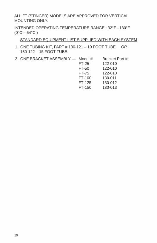
ALL FT (STINGER) MODELS ARE APPROVED FOR VERTICALMOUNTING ONLY.
INTENDED OPERATING TEMPERATURE RANGE : 32°F –130°F(0°C – 54°C )
STANDARD EQUIPMENT LIST SUPPLIED WITH EACH SYSTEM
1. ONE TUBING KIT, PART # 130-121 – 10 FOOT TUBE OR130-122 – 15 FOOT TUBE.
2. ONE BRACKET ASSEMBLY — Model # Bracket Part #FT-25 122-010FT-50 122-010FT-75 122-010FT-100 130-011FT-125 130-012FT-150 130-013
10
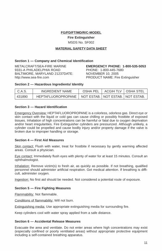
FG/FD/FT/MD/R/C-MODEL
Fire Extinguisher
MSDS No. SF002
MATERIAL SAFETY DATA SHEET
Section 1 — Company and Chemical Identification
METALCRAFT/SEA-FIRE MARINE EMERGENCY PHONE: 1-800-535-50539331-A PHILADELPHIA ROAD PHONE: 1-800-445-7680BALTIMORE, MARYLAND 21237DATE: NOVEMBER 10, 2005http://www.sea-fire.com PRODUCT NAME: Fire Extinguisher
Section 2 — Hazardous Ingredients/ Identity
C.A.S. INGREDIENT NAME OSHA PEL ACGIH TLV OSHA STEL
431890 HEPTAFLUOROPROPANE NOT ESTAB. NOT ESTAB. NOT ESTAB.
Section 3 — Hazard Identification
Emergency Overview: HEPTAFLUOROPROPANE is a colorless, odorless gas. Direct eye orskin contact with the liquid or cold gas can cause chilling or possibly frostbite of exposedtissues. Inhalation of high concentrations can be harmful or fatal due to oxygen deprivationand/or heart irregularities. Fire Extinguisher cylinders are pressurized. Although unlikely, acylinder could be propelled and cause bodily injury and/or property damage if the valve isbroken due to improper handling or storage.
Section 4 — First Aid Measures
Skin contact: Flush with water, treat for frostbite if necessary by gently warming affectedareas. Consult a physician.
Eye contact: Immediately flush eyes with plenty of water for at least 15 minutes. Consult anophthalmologist.
Inhalation: Remove victim(s) to fresh air, as quickly as possible. If not breathing, qualifiedpersonnel should administer artificial respiration. Get medical attention. If breathing is diffi-cult, administer oxygen.
Ingestion: No first aid should be needed. Not considered a potential route of exposure.
Section 5 — Fire Fighting Measures
Flammability: Not flammable.
Conditions of flammability: Will not burn.
Extinguishing media: Use appropriate extinguishing media for surrounding fire.
Keep cylinders cool with water spray applied from a safe distance.
Section 6 — Accidental Release Measures
Evacuate the area and ventilate. Do not enter areas where high concentrations may exist(especially confined or poorly ventilated areas) without appropriate protective equipmentincluding a self-contained breathing apparatus.
11
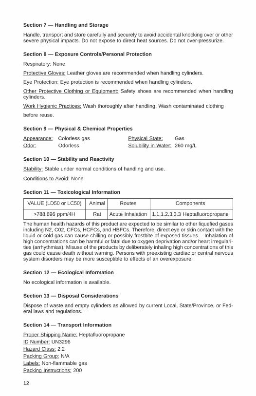
Section 7 — Handling and Storage
Handle, transport and store carefully and securely to avoid accidental knocking over or othersevere physical impacts. Do not expose to direct heat sources. Do not over-pressurize.
Section 8 — Exposure Controls/Personal Protection
Respiratory: None
Protective Gloves: Leather gloves are recommended when handling cylinders.
Eye Protection: Eye protection is recommended when handling cylinders.
Other Protective Clothing or Equipment: Safety shoes are recommended when handlingcylinders.
Work Hygienic Practices: Wash thoroughly after handling. Wash contaminated clothing
before reuse.
Section 9 — Physical & Chemical Properties
Appearance: Colorless gas Physical State: GasOdor: Odorless Solubility in Water: 260 mg/L
Section 10 — Stability and Reactivity
Stability: Stable under normal conditions of handling and use.
Conditions to Avoid: None
Section 11 — Toxicological Information
VALUE (LD50 or LC50) Animal Routes Components
>788.696 ppm/4H Rat Acute Inhalation 1.1.1.2.3.3.3 Heptafluoropropane
The human health hazards of this product are expected to be similar to other liquefied gasesincluding N2, C02, CFCs, HCFCs, and HBFCs. Therefore, direct eye or skin contact with theliquid or cold gas can cause chilling or possibly frostbite of exposed tissues. Inhalation ofhigh concentrations can be harmful or fatal due to oxygen deprivation and/or heart irregulari-ties (arrhythmias). Misuse of the products by deliberately inhaling high concentrations of thisgas could cause death without warning. Persons with preexisting cardiac or central nervoussystem disorders may be more susceptible to effects of an overexposure.
Section 12 — Ecological Information
No ecological information is available.
Section 13 — Disposal Considerations
Dispose of waste and empty cylinders as allowed by current Local, State/Province, or Fed-eral laws and regulations.
Section 14 — Transport Information
Proper Shipping Name: HeptafluoropropaneID Number: UN3296Hazard Class: 2.2Packing Group: N/ALabels: Non-flammable gasPacking Instructions: 200
12
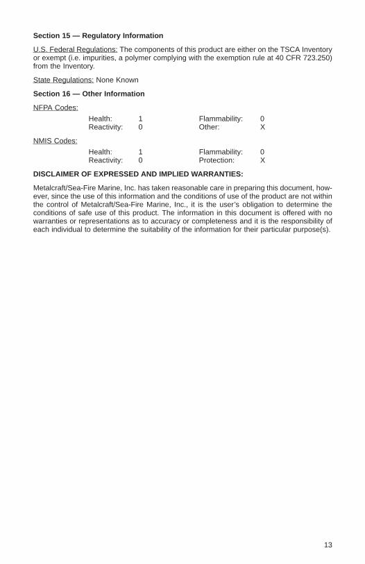
Section 15 — Regulatory Information
U.S. Federal Regulations: The components of this product are either on the TSCA Inventoryor exempt (i.e. impurities, a polymer complying with the exemption rule at 40 CFR 723.250)from the Inventory.
State Regulations: None Known
Section 16 — Other Information
NFPA Codes:
Health: 1 Flammability: 0Reactivity: 0 Other: X
NMIS Codes:
Health: 1 Flammability: 0Reactivity: 0 Protection: X
DISCLAIMER OF EXPRESSED AND IMPLIED WARRANTIES:
Metalcraft/Sea-Fire Marine, Inc. has taken reasonable care in preparing this document, how-ever, since the use of this information and the conditions of use of the product are not withinthe control of Metalcraft/Sea-Fire Marine, Inc., it is the user’s obligation to determine theconditions of safe use of this product. The information in this document is offered with nowarranties or representations as to accuracy or completeness and it is the responsibility ofeach individual to determine the suitability of the information for their particular purpose(s).
13
SEA-FIRE MARINE SEA-FIRE EUROPE LTDDivision of Metalcraft Inc. Unit 7. io Centre. Stephenson Road9331-A Philadelphia Road Fareham, HampshireBaltimore, Maryland 21237 USA PO15 5RU, United Kingdom
Website: www.sea-fire.com
14


![fm200[1] sample calculation.pdf](https://img.pdfslide.us/doc/110x75/55cf9c54550346d033a974ce/fm2001-sample-calculationpdf.jpg)