Embed Size (px)
Citation preview

Task 6 - Safety Review and LicensingOn the Job Training on Stress Analysis
Pisa (Italy)June 15 – July 14, 2015
F.M. with Finite Element analysis - Different calculation techniques + Numerical examples (ANSYS Workbench) 1/2
Davide Mazzini – Ciro Santus
2
Content
• Different FE techniques
• ANSYS Workbench
- Crack geometry element mesh preparation
- KI(II,III) and J calculation
- Examples
• ANSYS Apdl
- The quarter point technique
- Examples
FM parameters with Finite Element method
Pisa, June 15 – July 14, 2015
3
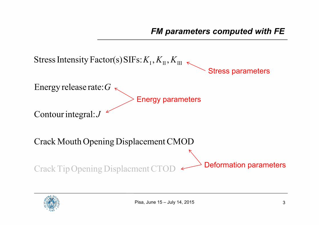
FM parameters computed with FE
I II IIIStress Intensity Factor(s)SIFs: , ,
Energy release rate:
Contour integral:
Crack Mouth Opening Displaceme
Crack Tip Opening Displ
n
acment CTOD
t CMOD
K K K
G
J
Stress parameters
Energy parameters
Deformation parameters
Pisa, June 15 – July 14, 2015
4
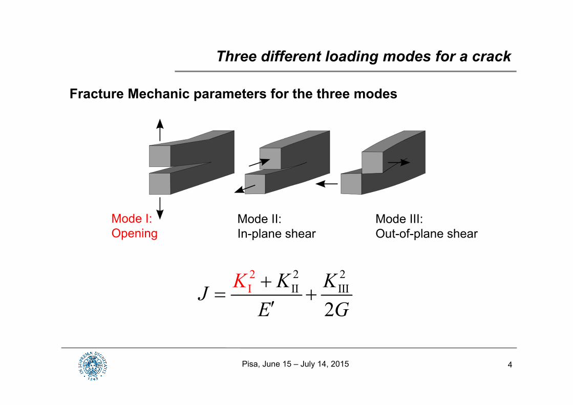
Fracture Mechanic parameters for the three modes
Three different loading modes for a crack
Mode I:Opening
Mode II:In-plane shear
Mode III:Out-of-plane shear
2 2I
2I II II
2K KJ K
E G
Pisa, June 15 – July 14, 2015
5
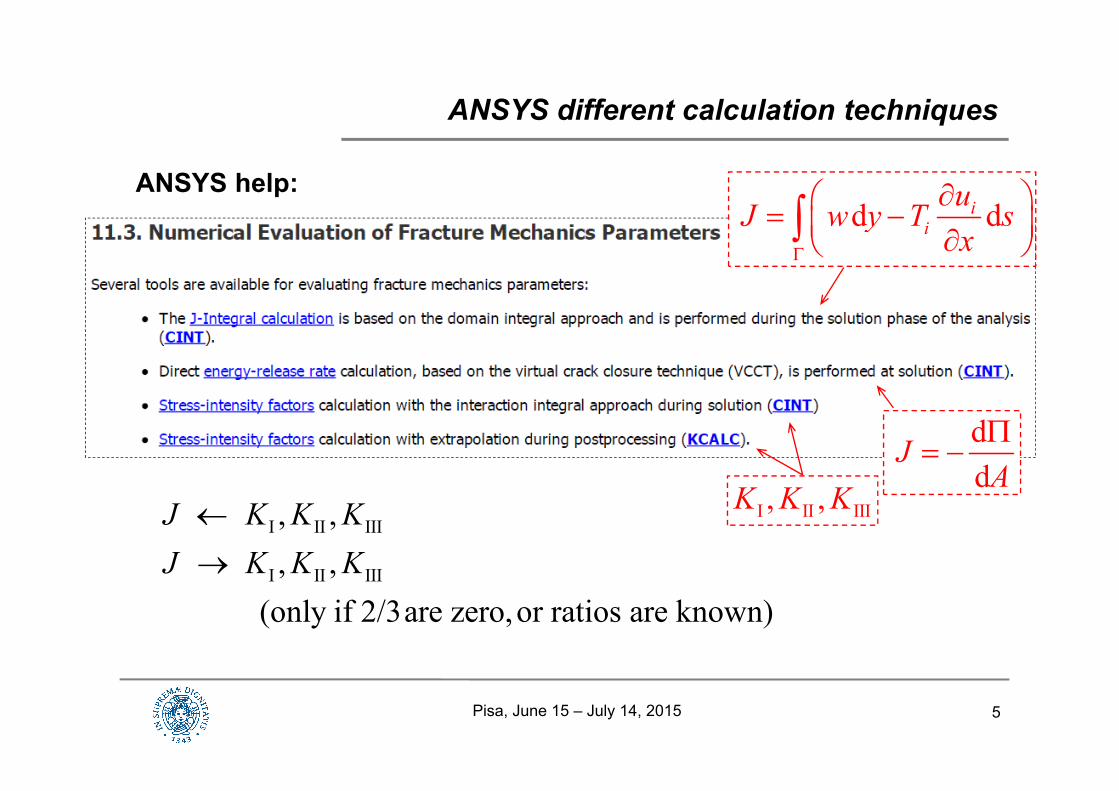
ANSYS help:
ANSYS different calculation techniques
d dii
uJ w y T sx
dd
JA
I II III, ,K K KI II III
I II III
, ,, ,
(only if 2/3are zero,or ratios are known)
J K K KJ K K K
Pisa, June 15 – July 14, 2015
6
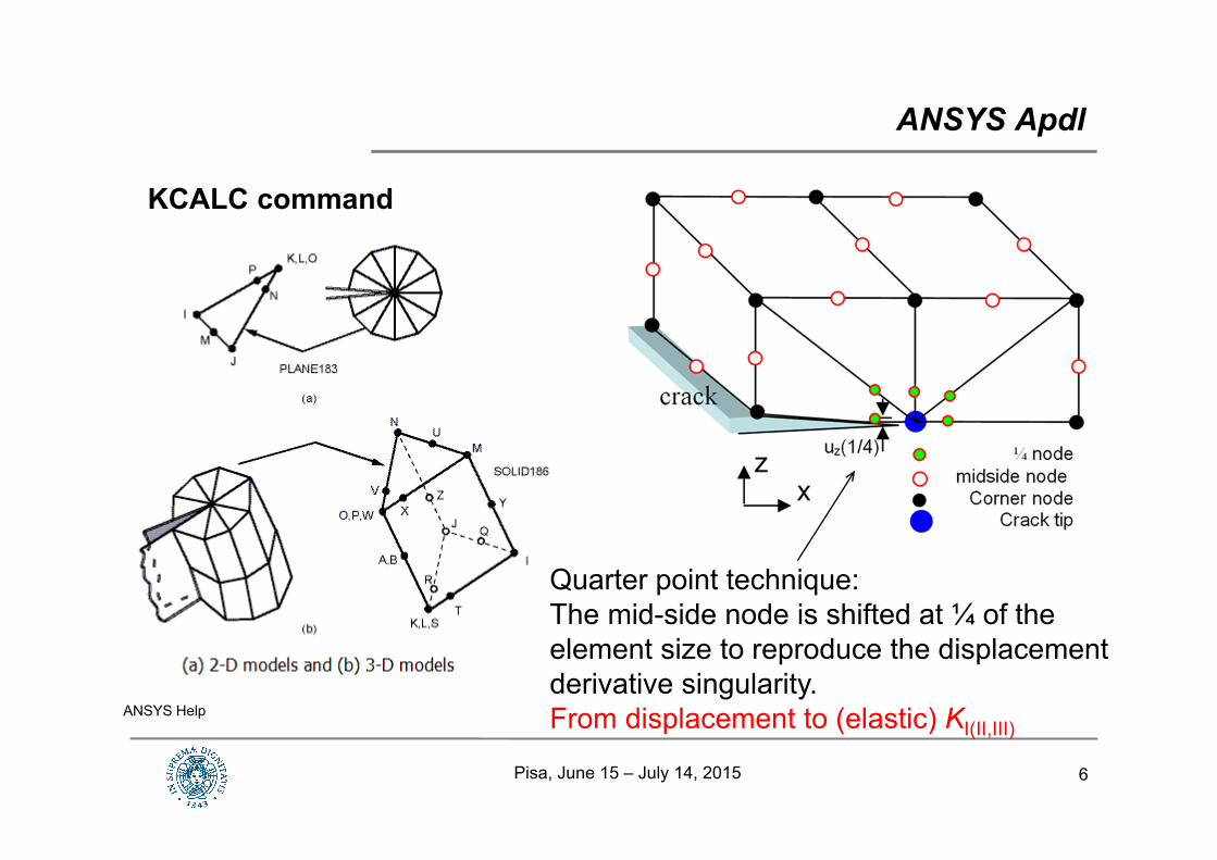
KCALC command
ANSYS Apdl
ANSYS Help
Quarter point technique:The mid-side node is shifted at ¼ of the element size to reproduce the displacement derivative singularity.From displacement to (elastic) KI(II,III)
Pisa, June 15 – July 14, 2015
7
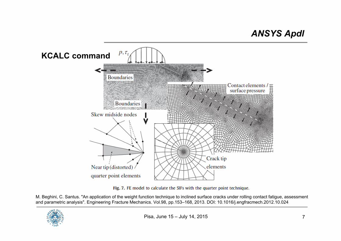
KCALC command
ANSYS Apdl
M. Beghini, C. Santus. "An application of the weight function technique to inclined surface cracks under rolling contact fatigue, assessment and parametric analysis". Engineering Fracture Mechanics. Vol.98, pp.153–168, 2013. DOI: 10.1016/j.engfracmech.2012.10.024
Pisa, June 15 – July 14, 2015
8
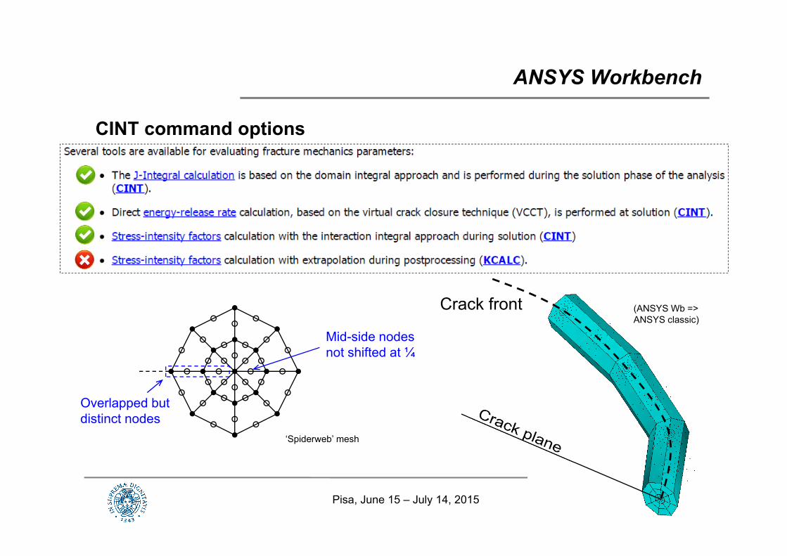
CINT command options
ANSYS Workbench
Crack front
Overlapped but distinct nodes
Mid-side nodes not shifted at ¼
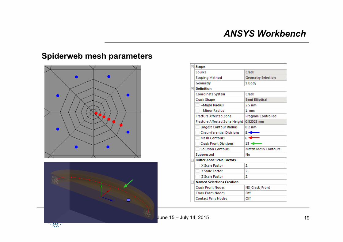
‘Spiderweb’ mesh
(ANSYS Wb =>ANSYS classic)
Pisa, June 15 – July 14, 2015
9
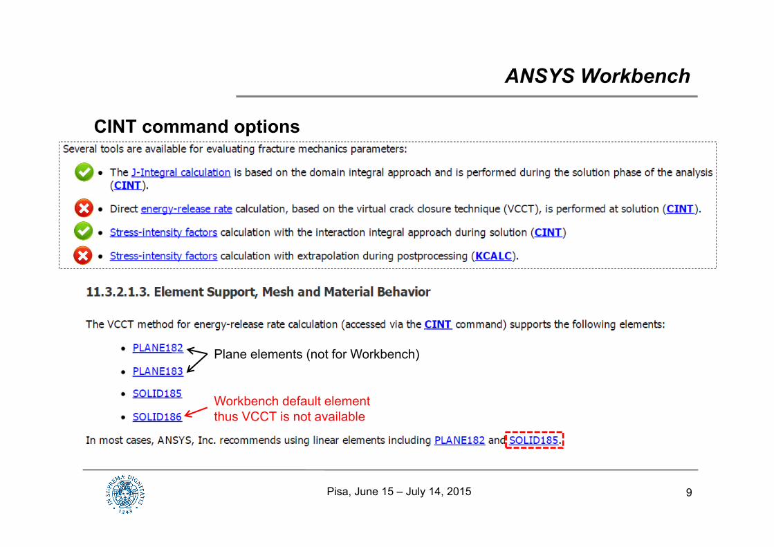
CINT command options
ANSYS Workbench
Workbench default elementthus VCCT is not available
Plane elements (not for Workbench)
Pisa, June 15 – July 14, 2015
10
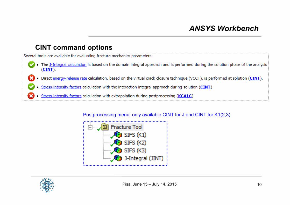
CINT command options
ANSYS Workbench
Postprocessing menu: only available CINT for J and CINT for K1(2,3)
Pisa, June 15 – July 14, 2015
11Pisa, June 15 – July 14, 2015
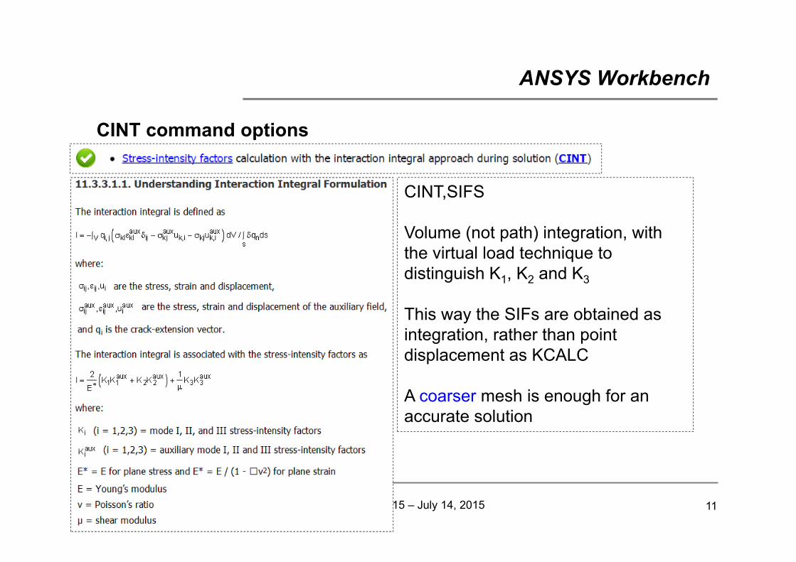
CINT command options
ANSYS Workbench
CINT,SIFS
Volume (not path) integration, with the virtual load technique to distinguish K1, K2 and K3
This way the SIFs are obtained as integration, rather than point displacement as KCALC
A coarser mesh is enough for an accurate solution
12
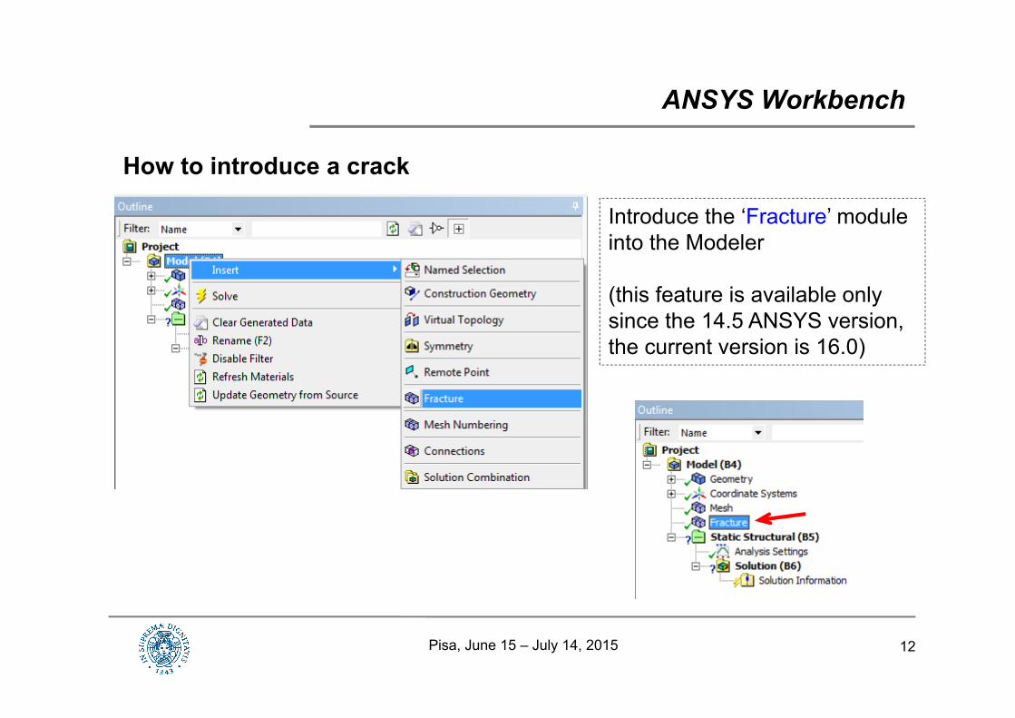
How to introduce a crack
ANSYS Workbench
Introduce the ‘Fracture’ module into the Modeler
(this feature is available only since the 14.5 ANSYS version, the current version is 16.0)
Pisa, June 15 – July 14, 2015

13
How to introduce a crack
ANSYS Workbench
1. It is possible to (easily) introduce a crack starting from a solid uncrackedbody and automatically generate the spiderweb mesh distribution at the crack front(Worth noting: this is for a semielliptical crack only)
2. Alternatively a (generic) crack front can be prepared in advance and introduced as the crack front
Pisa, June 15 – July 14, 2015

14
How to introduce a crack
Mesh preparation
ANSYS Workbench
Usually Hexahedrons are to be preferred than Tetrahedrons Here Tets are necessary for mesh continuity
Pisa, June 15 – July 14, 2015
15
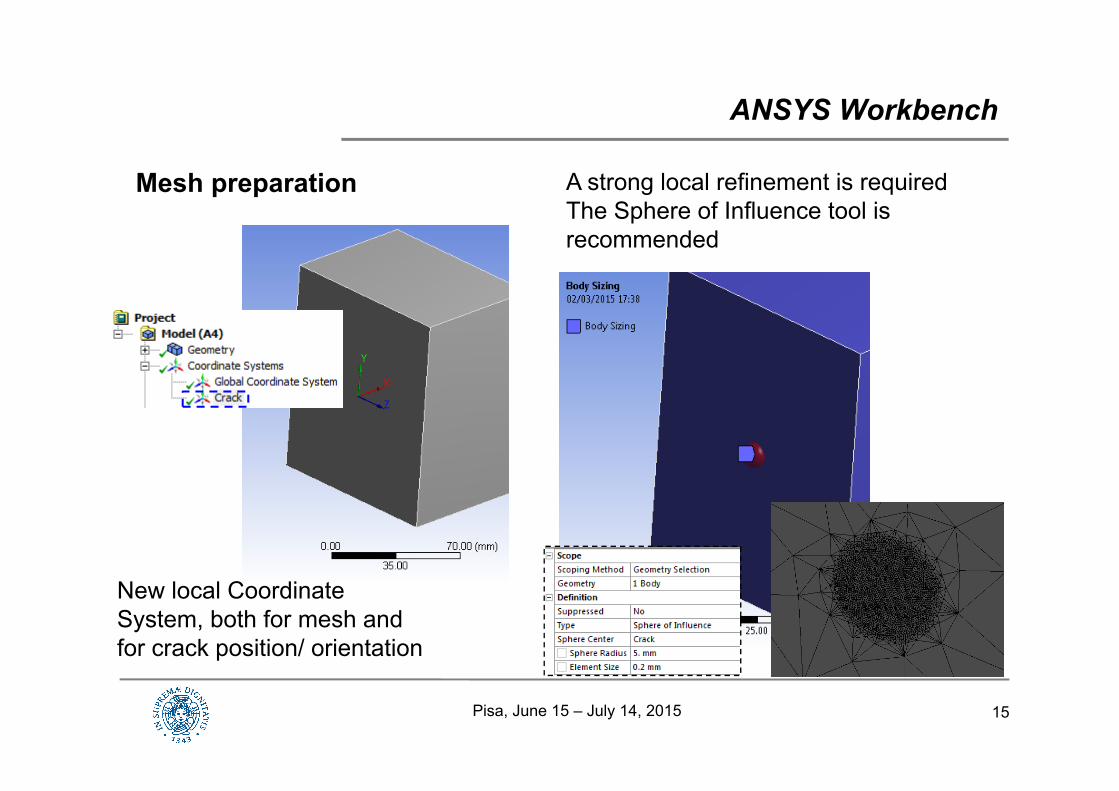
Mesh preparation
ANSYS Workbench
A strong local refinement is requiredThe Sphere of Influence tool is recommended
New local Coordinate System, both for mesh and for crack position/ orientation
Pisa, June 15 – July 14, 2015
16
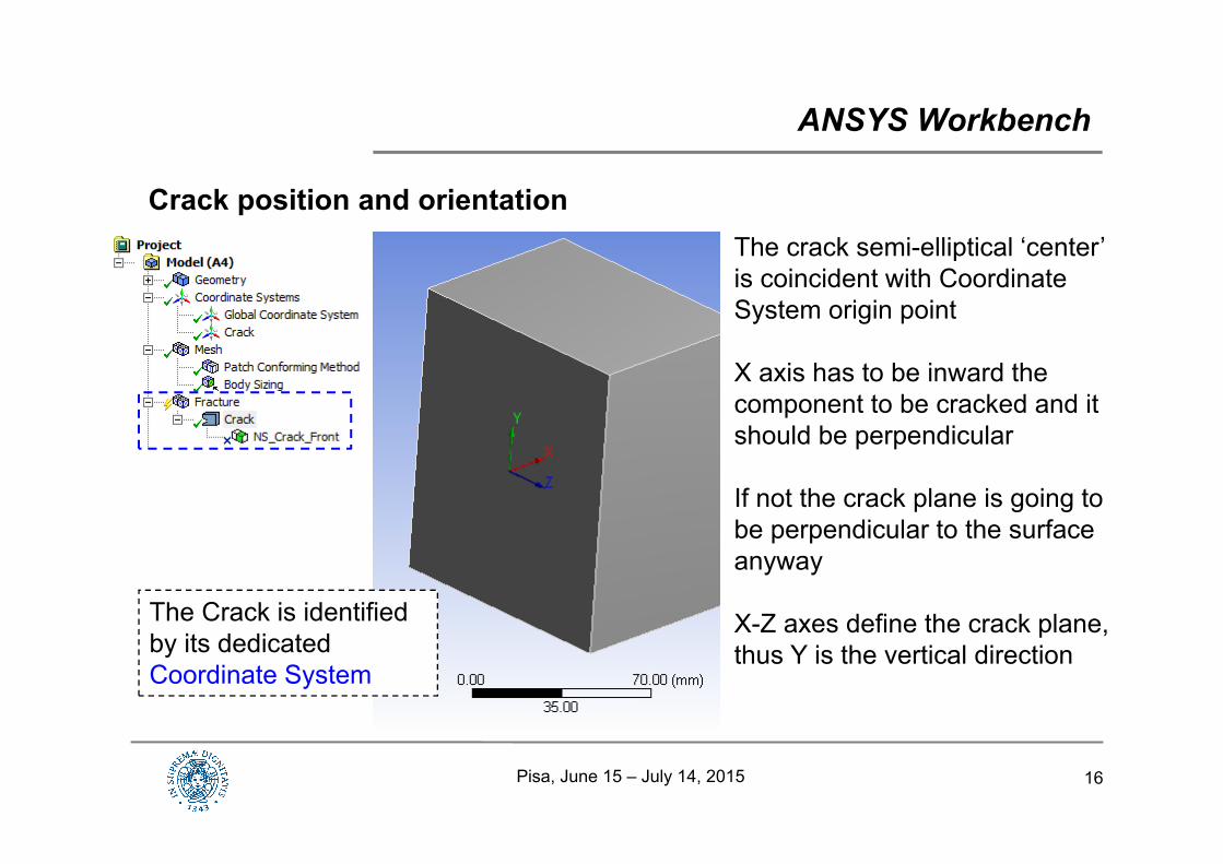
Crack position and orientation
ANSYS Workbench
The Crack is identified by its dedicated Coordinate System
The crack semi-elliptical ‘center’ is coincident with Coordinate System origin point
X axis has to be inward the component to be cracked and it should be perpendicular
If not the crack plane is going to be perpendicular to the surface anyway
X-Z axes define the crack plane, thus Y is the vertical direction
Pisa, June 15 – July 14, 2015
17
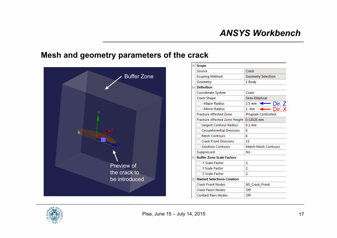
Mesh and geometry parameters of the crack
ANSYS Workbench
Dir. ZDir. X
Buffer Zone
Preview of the crack to be introduced
Pisa, June 15 – July 14, 2015
18
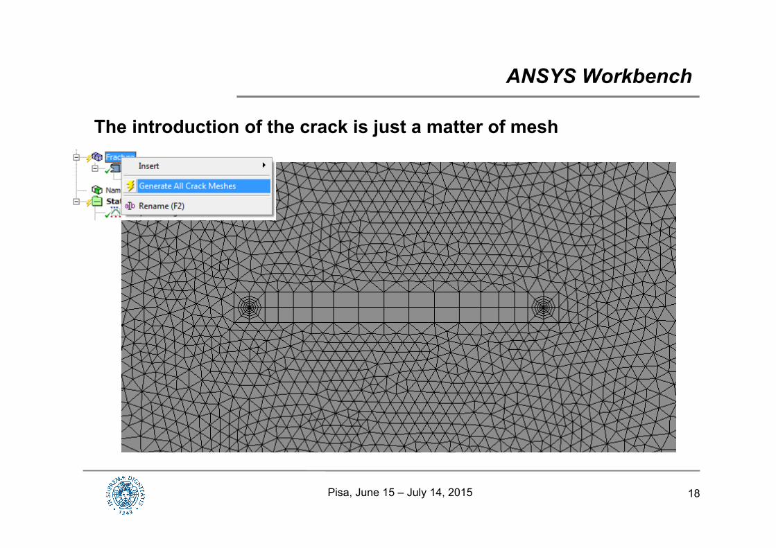
The introduction of the crack is just a matter of mesh
ANSYS Workbench
Pisa, June 15 – July 14, 2015
19Pisa, June 15 – July 14, 2015
Spiderweb mesh parameters
ANSYS Workbench
20
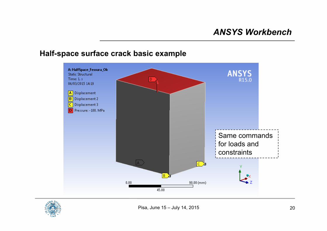
Half-space surface crack basic example
ANSYS Workbench
Same commands for loads and constraints
Pisa, June 15 – July 14, 2015
21Pisa, June 15 – July 14, 2015
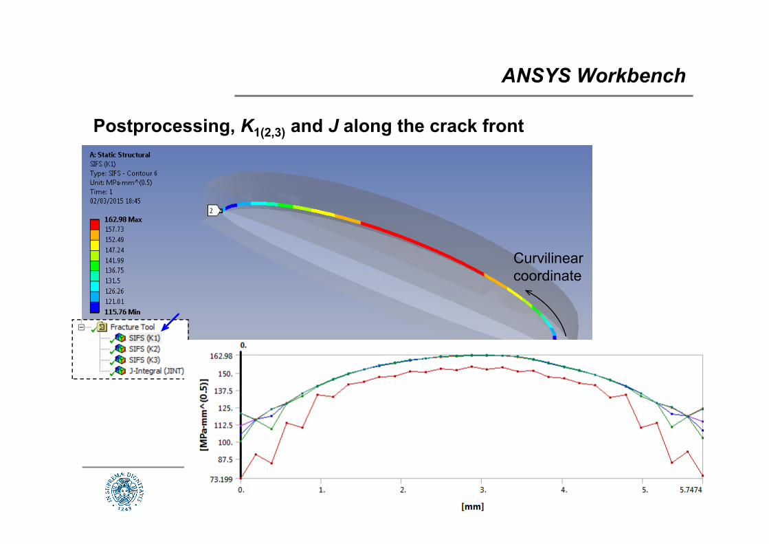
Postprocessing, K1(2,3) and J along the crack front
ANSYS Workbench
Curvilinear coordinate
22Pisa, June 15 – July 14, 2015
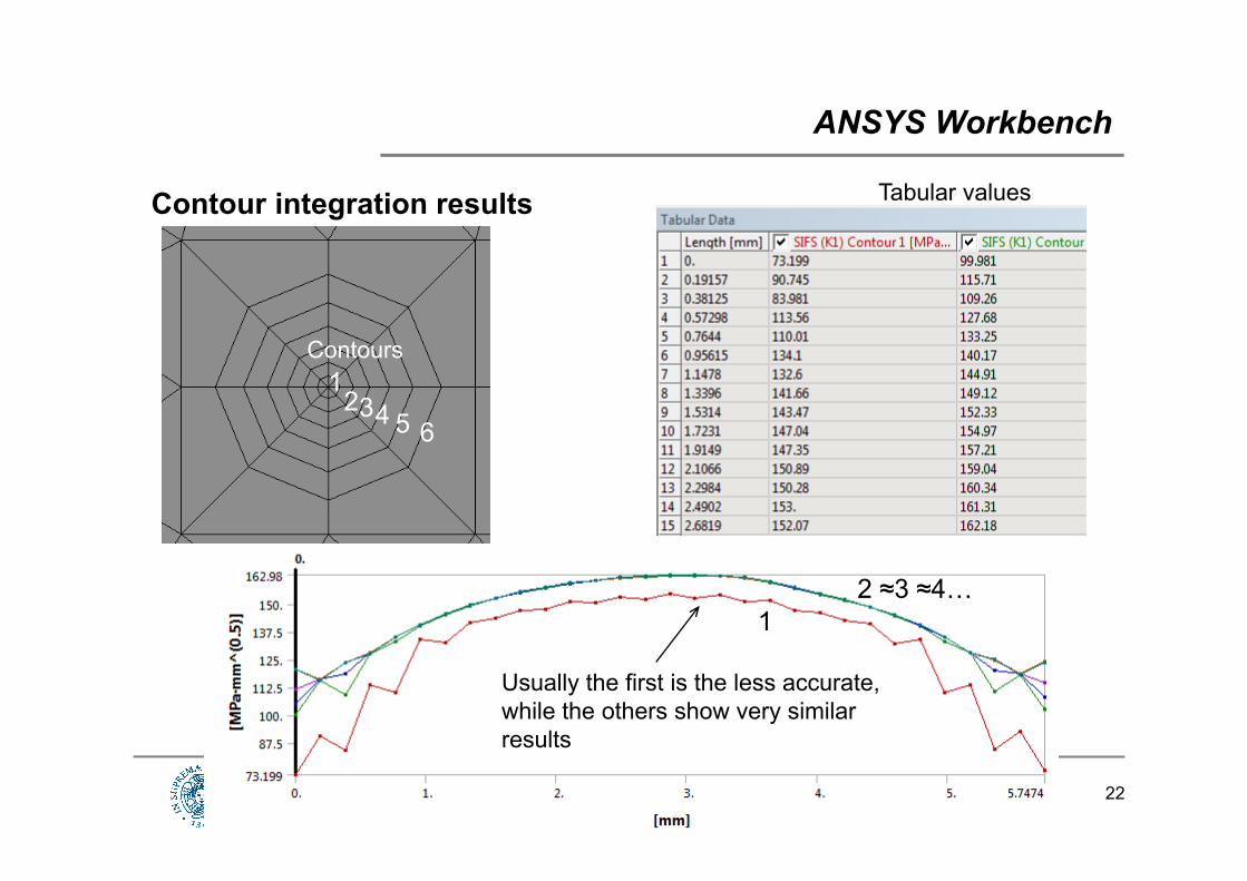
Contour integration results
ANSYS Workbench
32 4 5 6
1Contours
12 ≈3 ≈4…
Usually the first is the less accurate, while the others show very similar results
Tabular values
23Pisa, June 15 – July 14, 2015
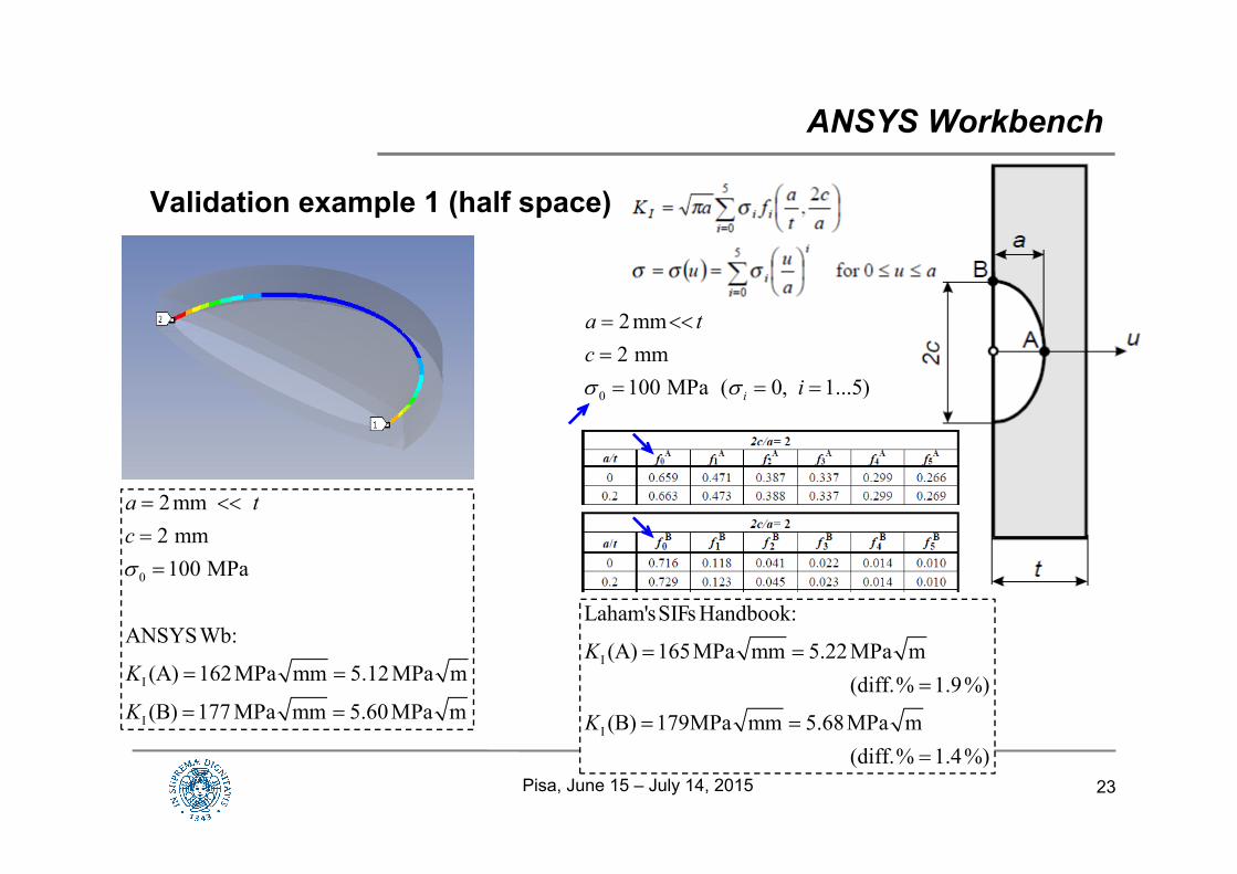
Validation example 1 (half space)
ANSYS Workbench
0
I
I
2mm 2 mm100 MPa
ANSYSWb:
(A) 162MPa mm 5.12MPa m
(B) 177 MPa mm 5.60MPa m
a tc
K
K
I
I
Laham'sSIFs Handbook:
(A) 165MPa mm 5.22 MPa m(diff.% 1.9%)
(B) 179MPa mm 5.68MPa m(diff.% 1.4%)
K
K
0
2mm2 mm100 MPa ( 0, 1...5)i
a tc
i
24Pisa, June 15 – July 14, 2015
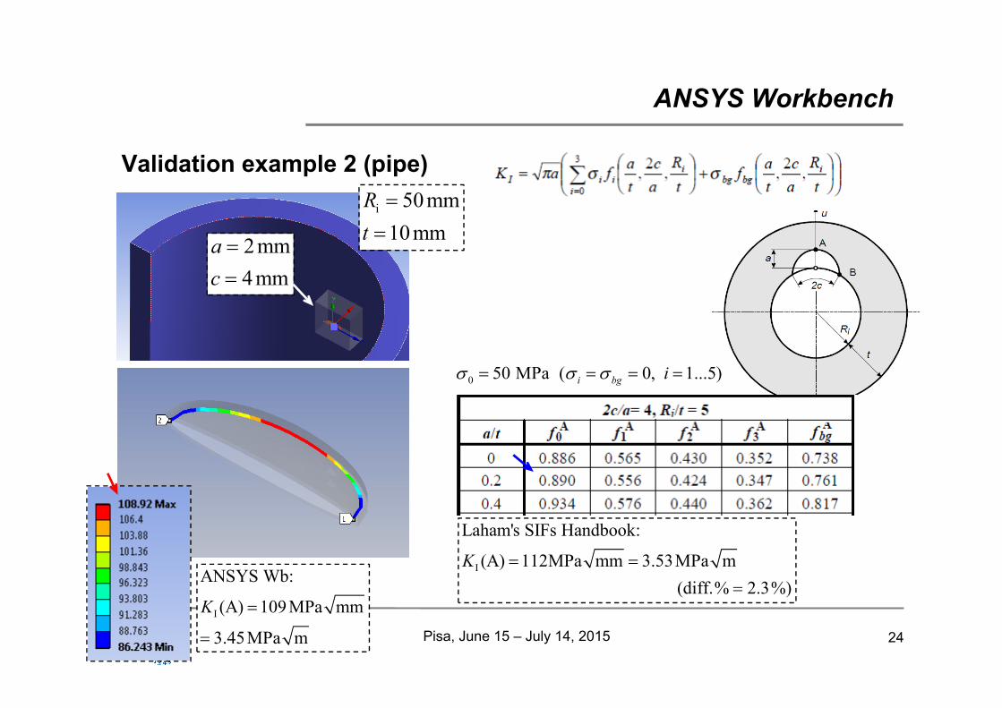
Validation example 2 (pipe)
ANSYS Workbench
I
Laham's SIFs Handbook:
(A) 112MPa mm 3.53MPa m(diff.% 2.3%)
K
0 50 MPa ( 0, 1...5)i bg i
I
ANSYS Wb:
(A) 109MPa mm
3.45MPa m
K
i 50 mm10 mm
Rt
2mm
4 mmac
25Pisa, June 15 – July 14, 2015
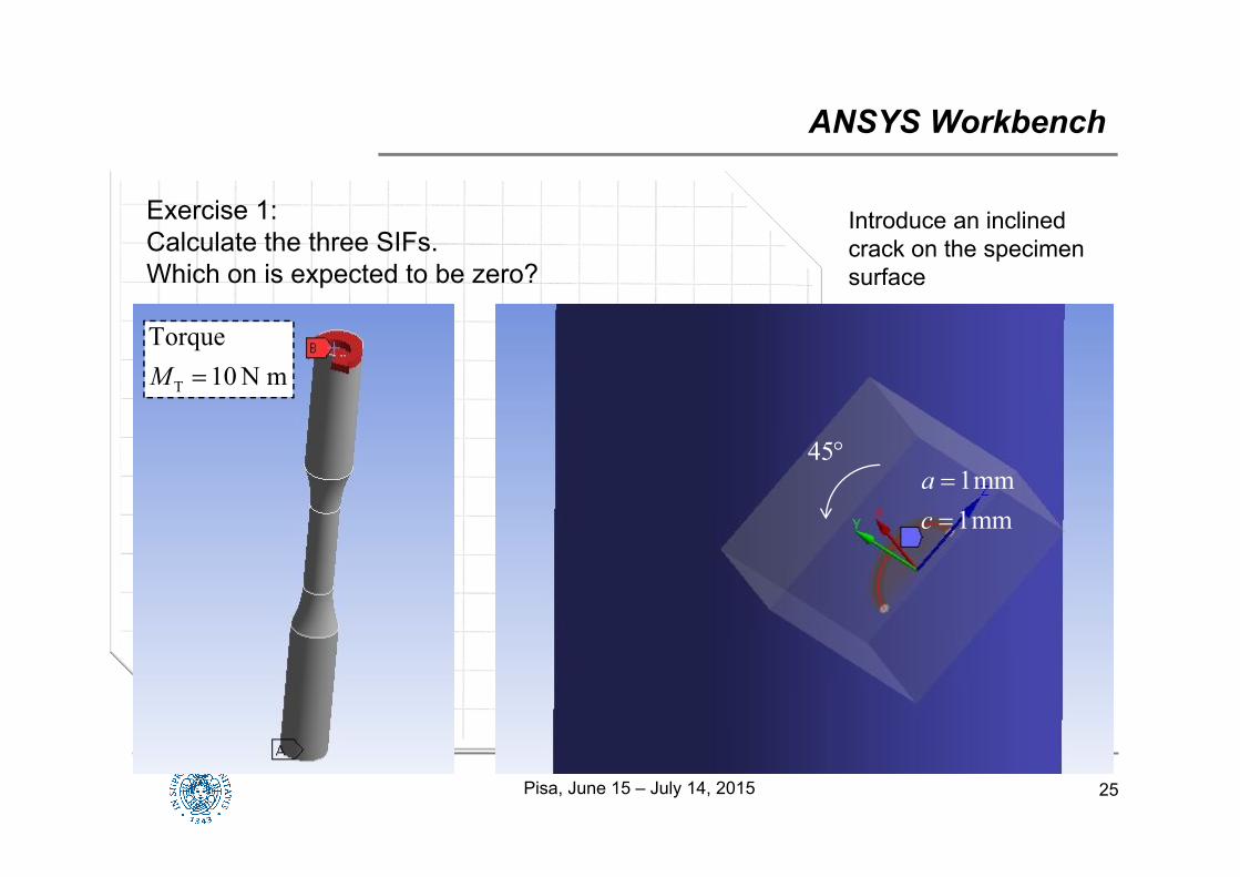
ANSYS Workbench
Exercise 1:Calculate the three SIFs.Which on is expected to be zero?
T
Torque10 N mM
45
Introduce an inclined crack on the specimen surface
1mm1mm
ac
26
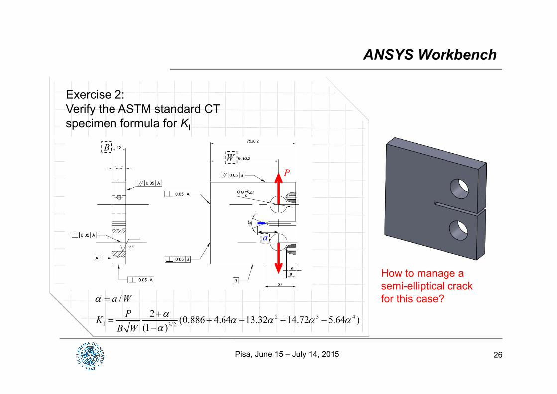
ANSYS Workbench
Exercise 2:Verify the ASTM standard CT specimen formula for KI
WB
P
a
2 3 4I 3/2
/2 (0.886 4.64 13.32 14.72 5.64 )
(1 )
a WPK
B W
How to manage a semi-elliptical crack for this case?
Pisa, June 15 – July 14, 2015
27
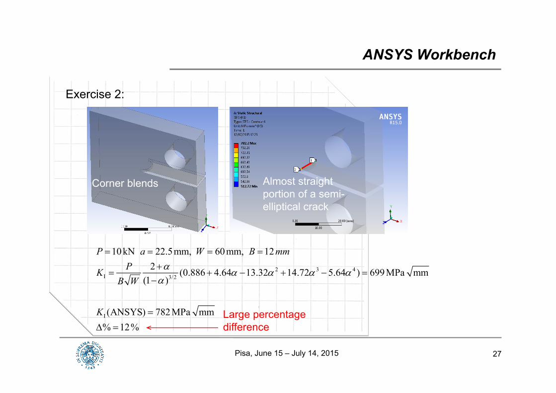
ANSYS Workbench
Exercise 2:
2 3 4I 3/2
I
10 kN 22.5mm, 60mm, 122 (0.886 4.64 13.32 14.72 5.64 ) 699MPa mm
(1 )
(ANSYS) 782MPa mm% 12%
P a W B mmPK
B W
K
Corner blends Almost straight portion of a semi-elliptical crack
Large percentage difference
Pisa, June 15 – July 14, 2015
28
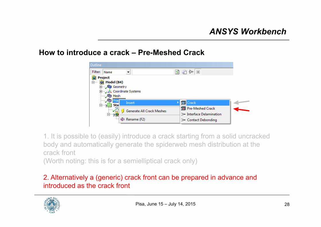
How to introduce a crack – Pre-Meshed Crack
ANSYS Workbench
1. It is possible to (easily) introduce a crack starting from a solid uncrackedbody and automatically generate the spiderweb mesh distribution at the crack front(Worth noting: this is for a semielliptical crack only)
2. Alternatively a (generic) crack front can be prepared in advance and introduced as the crack front
Pisa, June 15 – July 14, 2015
29
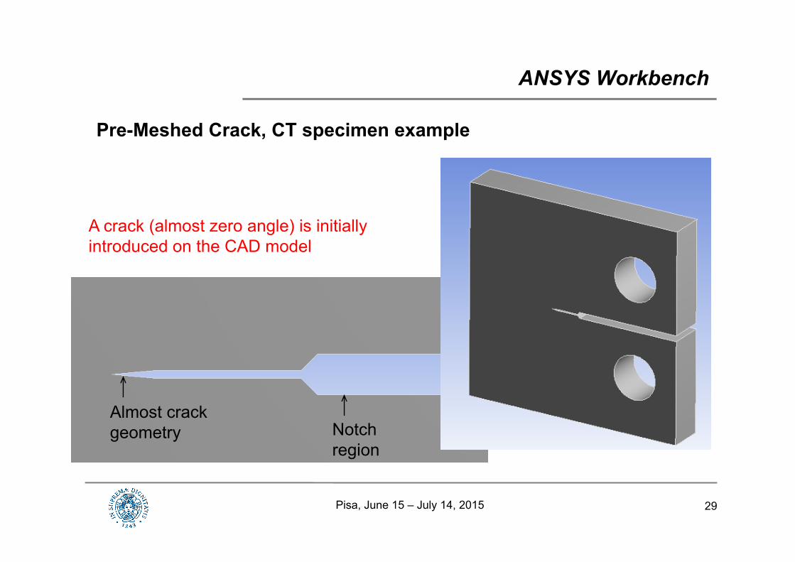
Pre-Meshed Crack, CT specimen example
ANSYS Workbench
A crack (almost zero angle) is initially introduced on the CAD model
Notch region
Almost crack geometry
Pisa, June 15 – July 14, 2015
30Pisa, June 15 – July 14, 2015
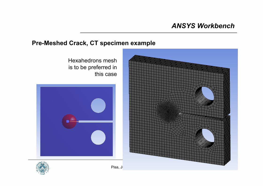
Pre-Meshed Crack, CT specimen example
ANSYS Workbench
Hexahedrons mesh is to be preferred in
this case
31
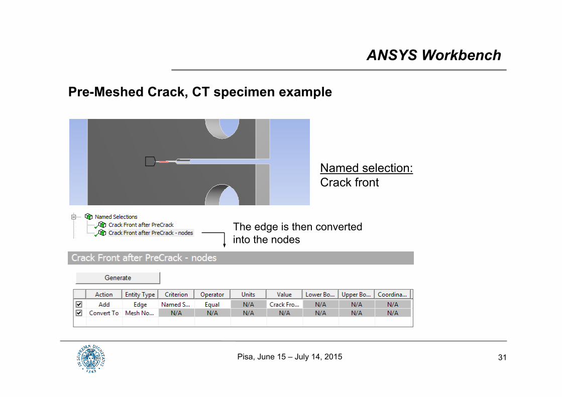
Pre-Meshed Crack, CT specimen example
ANSYS Workbench
Named selection:Crack front
The edge is then converted into the nodes
Pisa, June 15 – July 14, 2015
32
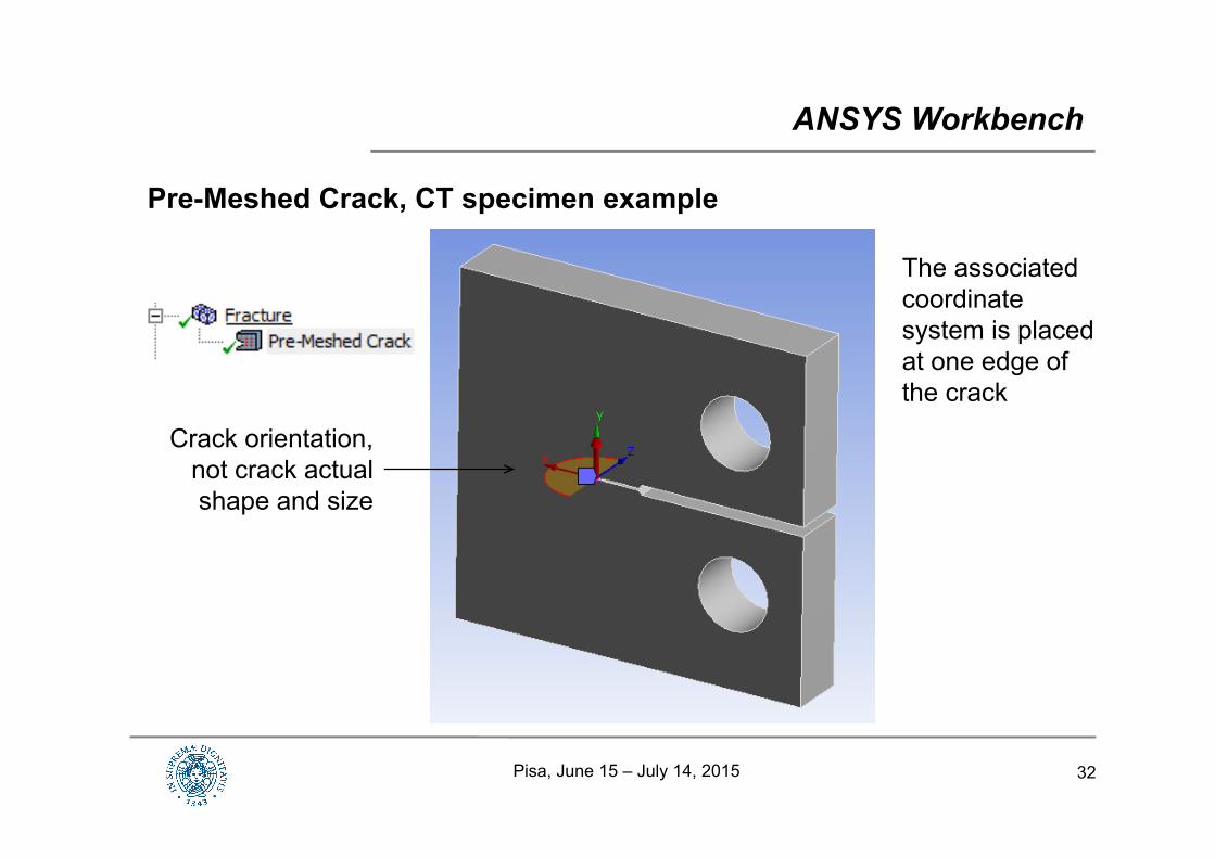
Pre-Meshed Crack, CT specimen example
ANSYS Workbench
Crack orientation, not crack actual shape and size
The associated coordinate system is placed at one edge of the crack
Pisa, June 15 – July 14, 2015
33
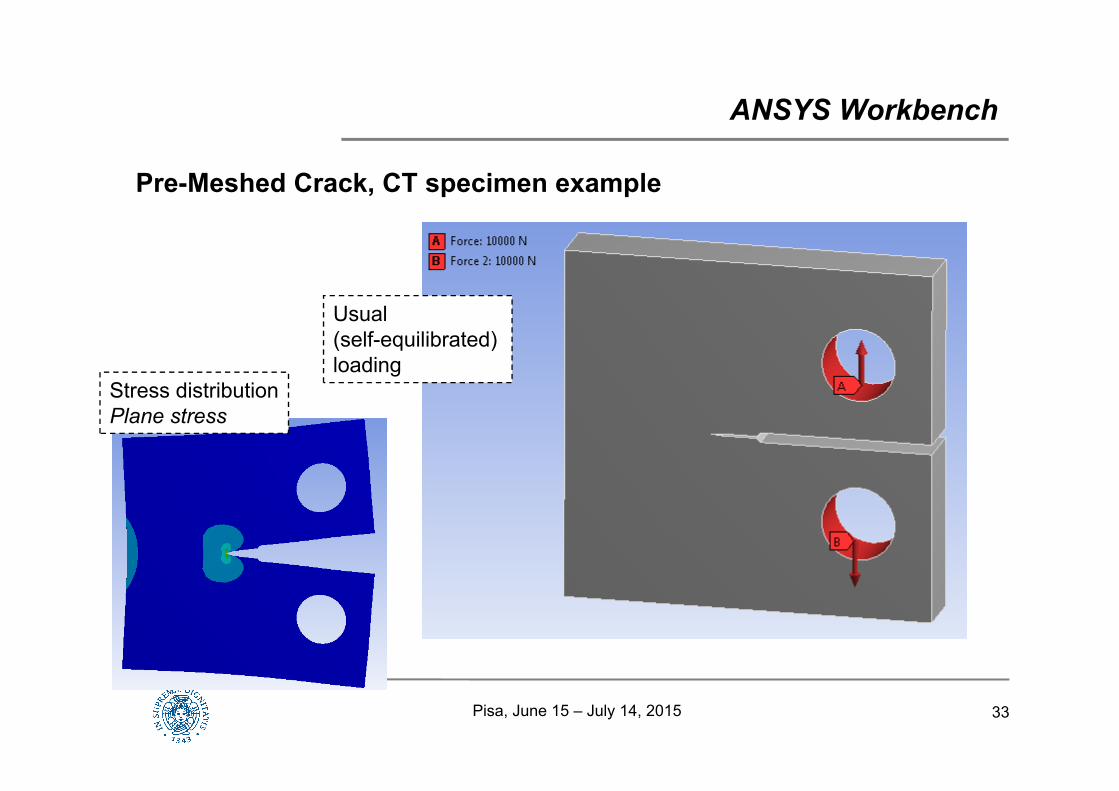
Pre-Meshed Crack, CT specimen example
ANSYS Workbench
Usual(self-equilibrated)loading
Stress distributionPlane stress
Pisa, June 15 – July 14, 2015
34
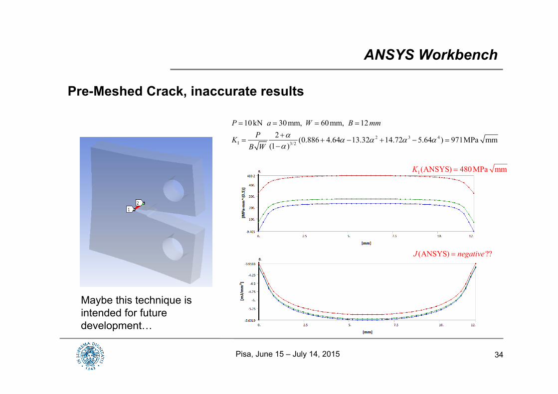
Pre-Meshed Crack, inaccurate results
ANSYS Workbench
2 3 4I 3/2
10 kN 30 mm, 60 mm, 122 (0.886 4.64 13.32 14.72 5.64 ) 971MPa mm
(1 )
P a W B mmPK
B W
I (ANSYS) 480 MPa mmK
(ANSYS) ??J negative
Maybe this technique is intended for future development…
Pisa, June 15 – July 14, 2015