Embed Size (px)
Citation preview
FM 5-410
CHAPTER 2
S t r u c t u r a l G e o l o g y
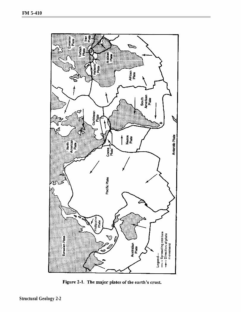
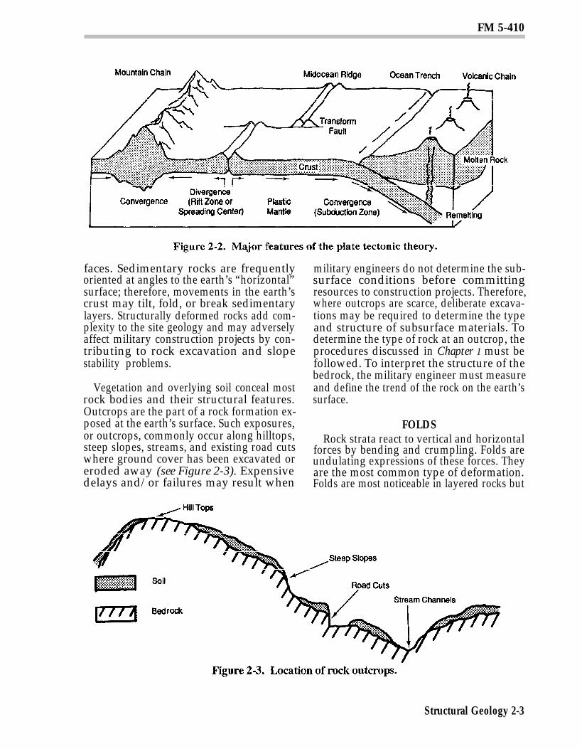
Structural geology describes the form, pat-tern, origin, and internal structure of rockand soil masses. Tectonics, a closely relatedfield, deals with structural features on alarger regional, continental, or global scale.Figure 2-1, page 2-2, shows the major plates ofthe earth’s crust. These plates continuallyundergo movement as shown by the arrows.Figure 2-2, page 2-3, is a more detailed repre-sentation of plate tectonic theory. Moltenmaterial rises to the earth’s surface atmidoceanic ridges, forcing the oceanic platesto diverge. These plates, in turn, collide withadjacent plates, which may or may not be ofsimilar density. If the two colliding plates areof approximately equal density, the plateswill crumple, forming mountain range alongthe convergent zone. If, on the other hand,one of the plates is more dense than the other,it will be subducted, or forced below, thelighter plate, creating an oceanic trench alongthe convergent zone. Active volcanism andseismic activity can be expected in the vicinityof plate boundaries. In addition, military en-gineers must also deal with geologic featuresthat exist on a smaller scale than that of platetectonics but which are directly related to thereformational processes resulting from theforce and movements of plate tectonics.
The determination of geologic structure isoften made by careful study of the stratig-raphy and sedimentation characteristics oflayered rocks. The primary structure ororiginal form and arrangement of rock bod-ies in the earth’s crust is often altered by
secondary structural features. These secon-dary features include folds, faults, joints, andschistosity. These features can be identifiedand m appeal in the field through site inves-tigation and from remote imagery.
Section I. Structural Featuresin Sedimentary Rocks
BEDDING PLANESStructural features are most readily recog-
nized in the sedimentary rocks. They arenormally deposited in more or less regularhorizontal layers that accumulate on top ofeach other in an orderly sequence. Individualdeposits within the sequence are separatedby planar contact surfaces called beddingplanes (see Figure 1-7, page 1-9). Beddingplanes are of great importance to military en-gineers. They are planes of structuralweakness in sedimentary rocks, and massesof rock can move along them causing rockslides. Since over 75 percent of the earth’ssurface is made up of sedimentary rocks,military engineers can expect to frequentlyencounter these rocks during construction.
Undisturbed sedimentary rocks may berelatively uniform, continuous, and predict-able across a site. These types of rocks offercertain advantages to military engineers incompleting horizontal and vertical construc-tion missions. They are relatively stable rockbodies that allow for ease of rock excavation,as they will normally support steep rock
Structural Geology 2-1
FM 5-410
Structural Geology 2-2
FM 5-410
faces. Sedimentary rocks are frequentlyoriented at angles to the earth’s “horizontal”surface; therefore, movements in the earth’scrust may tilt, fold, or break sedimentarylayers. Structurally deformed rocks add com-plexity to the site geology and may adverselyaffect military construction projects by con-tributing to rock excavation and slopestability problems.
Vegetation and overlying soil conceal mostrock bodies and their structural features.Outcrops are the part of a rock formation ex-posed at the earth’s surface. Such exposures,or outcrops, commonly occur along hilltops,steep slopes, streams, and existing road cutswhere ground cover has been excavated oreroded away (see Figure 2-3). Expensivedelays and/or failures may result when
military engineers do not determine the sub-surface conditions before committingresources to construction projects. Therefore,where outcrops are scarce, deliberate excava-tions may be required to determine the typeand structure of subsurface materials. Todetermine the type of rock at an outcrop, theprocedures discussed in Chapter 1 must befollowed. To interpret the structure of thebedrock, the military engineer must measureand define the trend of the rock on the earth’ssurface.
FOLDSRock strata react to vertical and horizontal
forces by bending and crumpling. Folds areundulating expressions of these forces. Theyare the most common type of deformation.Folds are most noticeable in layered rocks but
Structural Geology 2-3
FM 5-410
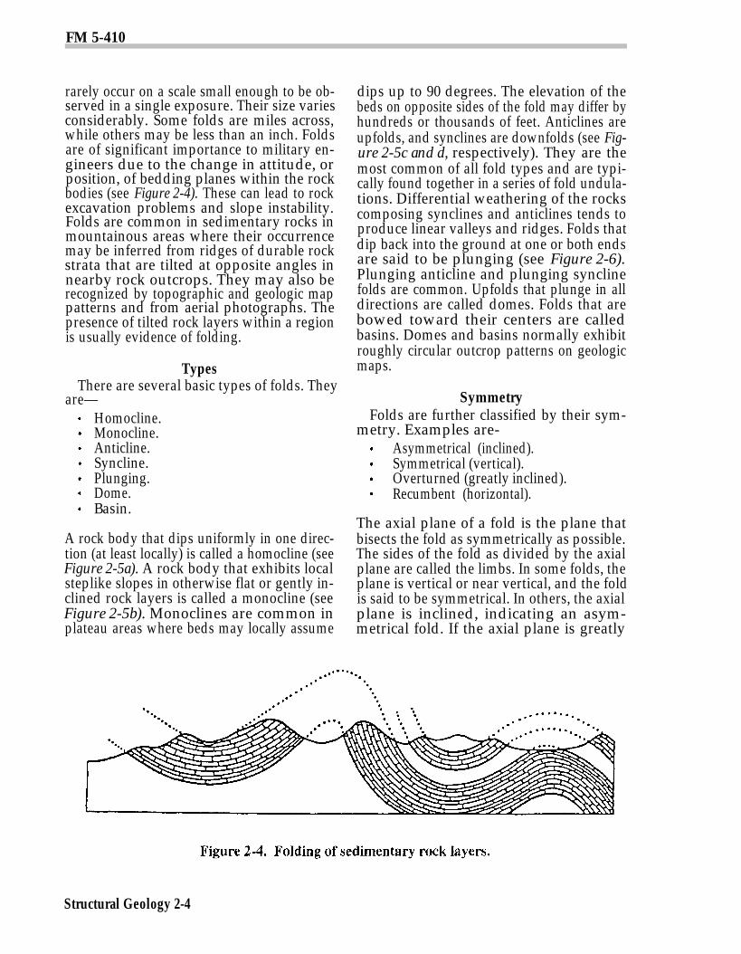
rarely occur on a scale small enough to be ob-served in a single exposure. Their size variesconsiderably. Some folds are miles across,while others may be less than an inch. Foldsare of significant importance to military en-gineers due to the change in attitude, orposition, of bedding planes within the rockbodies (see Figure 2-4). These can lead to rockexcavation problems and slope instability.Folds are common in sedimentary rocks inmountainous areas where their occurrencemay be inferred from ridges of durable rockstrata that are tilted at opposite angles innearby rock outcrops. They may also berecognized by topographic and geologic mappatterns and from aerial photographs. Thepresence of tilted rock layers within a regionis usually evidence of folding.
TypesThere are several basic types of folds. They
are—Homocline.Monocline.Anticline.Syncline.Plunging.Dome.Basin.
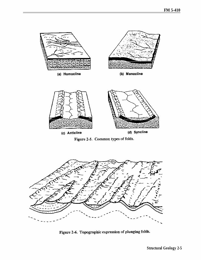
A rock body that dips uniformly in one direc-tion (at least locally) is called a homocline (seeFigure 2-5a). A rock body that exhibits localsteplike slopes in otherwise flat or gently in-clined rock layers is called a monocline (seeFigure 2-5b). Monoclines are common inplateau areas where beds may locally assume
dips up to 90 degrees. The elevation of thebeds on opposite sides of the fold may differ byhundreds or thousands of feet. Anticlines areupfolds, and synclines are downfolds (see Fig-ure 2-5c and d, respectively). They are themost common of all fold types and are typi-cally found together in a series of fold undula-tions. Differential weathering of the rockscomposing synclines and anticlines tends toproduce linear valleys and ridges. Folds thatdip back into the ground at one or both endsare said to be plunging (see Figure 2-6).Plunging anticline and plunging synclinefolds are common. Upfolds that plunge in alldirections are called domes. Folds that arebowed toward their centers are calledbasins. Domes and basins normally exhibitroughly circular outcrop patterns on geologicmaps.
SymmetryFolds are further classified by their sym-
metry. Examples are-Asymmetrical (inclined).Symmetrical (vertical).Overturned (greatly inclined).Recumbent (horizontal).
The axial plane of a fold is the plane thatbisects the fold as symmetrically as possible.The sides of the fold as divided by the axialplane are called the limbs. In some folds, theplane is vertical or near vertical, and the foldis said to be symmetrical. In others, the axialplane is inclined, indicating an asym-metrical fold. If the axial plane is greatly
Structural Geology 2-4
FM 5-410
Structural Geology 2-5
FM 5-410
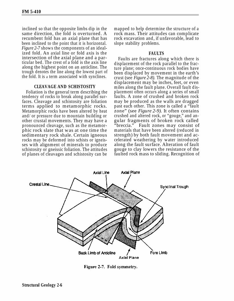
inclined so that the opposite limbs dip in thesame direction, the fold is overturned. Arecumbent fold has an axial plane that hasbeen inclined to the point that it is horizontal.Figure 2-7 shows the components of an ideal-ized fold. An axial line or fold axis is theintersection of the axial plane and a par-ticular bed. The crest of a fold is the axis linealong the highest point on an anticline. Thetrough denotes the line along the lowest part ofthe fold. It is a term associated with synclines.
CLEAVAGE AND SCHISTOSITYFoliation is the general term describing the
tendency of rocks to break along parallel sur-faces. Cleavage and schistosity are foliationterms applied to metamorphic rocks.Metamorphic rocks have been altered by heatand/or pressure due to mountain building orother crustal movements. They may have apronounced cleavage, such as the metamor-phic rock slate that was at one time thesedimentary rock shale. Certain igneousrocks may be deformed into schists or igneis-ses with alignment of minerals to produceschistosity or gneissic foliation. The attitudesof planes of cleavages and schistosity can be
mapped to help determine the structure of arock mass. Their attitudes can complicaterock excavation and, if unfavorable, lead toslope stability problems.
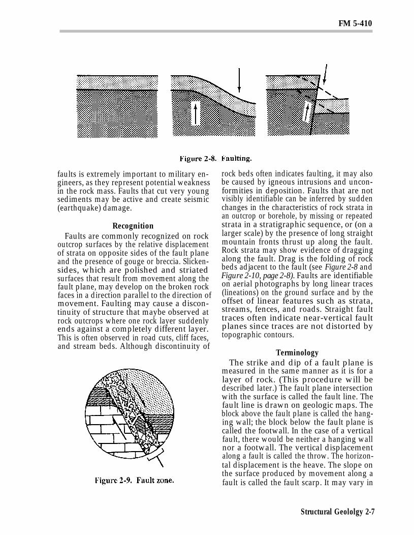
FAULTSFaults are fractures along which there is
displacement of the rock parallel to the frac-ture plane; once-continuous rock bodies havebeen displaced by movement in the earth’scrust (see Figure 2-8). The magnitude of thedisplacement may be inches, feet, or evenmiles along the fault plane. Overall fault dis-placement often occurs along a series of smallfaults. A zone of crushed and broken rockmay be produced as the walls are draggedpast each other. This zone is called a “faultzone” (see Figure 2-9). It often containscrushed and altered rock, or “gouge,” and an-gular fragments of broken rock called“breccia.” Fault zones may consist ofmaterials that have been altered (reduced instrength) by both fault movement and ac-celerated weathering by water introducedalong the fault surface. Alteration of faultgouge to clay lowers the resistance of thefaulted rock mass to sliding. Recognition of
Structural Geology 2-6
FM 5-410
faults is extremely important to military en-gineers, as they represent potential weaknessin the rock mass. Faults that cut very youngsediments may be active and create seismic(earthquake) damage.
RecognitionFaults are commonly recognized on rock
outcrop surfaces by the relative displacementof strata on opposite sides of the fault planeand the presence of gouge or breccia. Slicken-sides, which are polished and striatedsurfaces that result from movement along thefault plane, may develop on the broken rockfaces in a direction parallel to the direction ofmovement. Faulting may cause a discon-tinuity of structure that maybe observed atrock outcrops where one rock layer suddenlyends against a completely different layer.This is often observed in road cuts, cliff faces,and stream beds. Although discontinuity of
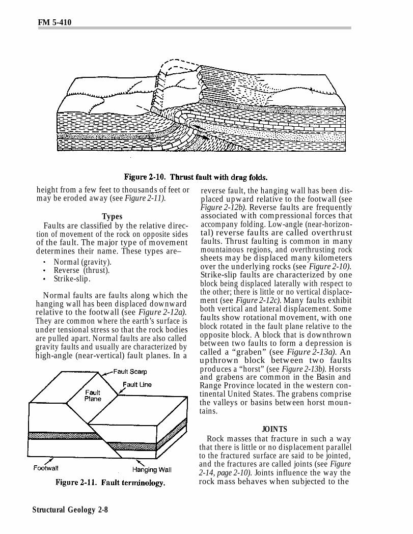
rock beds often indicates faulting, it may alsobe caused by igneous intrusions and uncon-formities in deposition. Faults that are notvisibly identifiable can be inferred by suddenchanges in the characteristics of rock strata inan outcrop or borehole, by missing or repeatedstrata in a stratigraphic sequence, or (on alarger scale) by the presence of long straightmountain fronts thrust up along the fault.Rock strata may show evidence of draggingalong the fault. Drag is the folding of rockbeds adjacent to the fault (see Figure 2-8 andFigure 2-10, page 2-8). Faults are identifiableon aerial photographs by long linear traces(lineations) on the ground surface and by theoffset of linear features such as strata,streams, fences, and roads. Straight faulttraces often indicate near-vertical faultplanes since traces are not distorted bytopographic contours.
TerminologyThe strike and dip of a fault plane is
measured in the same manner as it is for alayer of rock. (This procedure will bedescribed later.) The fault plane intersectionwith the surface is called the fault line. Thefault line is drawn on geologic maps. Theblock above the fault plane is called the hang-ing wall; the block below the fault plane iscalled the footwall. In the case of a verticalfault, there would be neither a hanging wallnor a footwall. The vertical displacementalong a fault is called the throw. The horizon-tal displacement is the heave. The slope onthe surface produced by movement along afault is called the fault scarp. It may vary in
Structural Geololgy 2-7
FM 5-410
height from a few feet to thousands of feet ormay be eroded away (see Figure 2-11).
TypesFaults are classified by the relative direc-
tion of movement of the rock on opposite sidesof the fault. The major type of movementdetermines their name. These types are–
Normal (gravity).Reverse (thrust).Strike-slip.
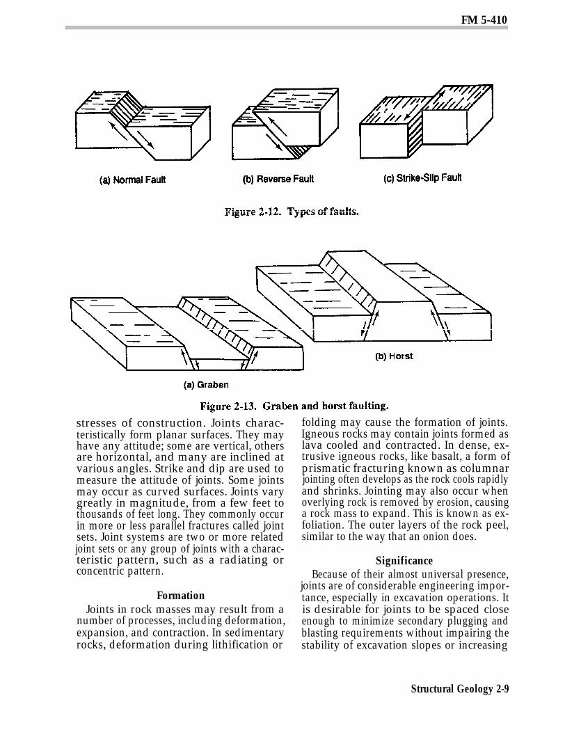
Normal faults are faults along which thehanging wall has been displaced downwardrelative to the footwall (see Figure 2-12a).They are common where the earth’s surface isunder tensional stress so that the rock bodiesare pulled apart. Normal faults are also calledgravity faults and usually are characterized byhigh-angle (near-vertical) fault planes. In a
reverse fault, the hanging wall has been dis-placed upward relative to the footwall (seeFigure 2-12b). Reverse faults are frequentlyassociated with compressional forces thataccompany folding. Low-angle (near-horizon-tal) reverse faults are called overthrustfaults. Thrust faulting is common in manymountainous regions, and overthrusting rocksheets may be displaced many kilometersover the underlying rocks (see Figure 2-10).Strike-slip faults are characterized by oneblock being displaced laterally with respect tothe other; there is little or no vertical displace-ment (see Figure 2-12c). Many faults exhibitboth vertical and lateral displacement. Somefaults show rotational movement, with oneblock rotated in the fault plane relative to theopposite block. A block that is downthrownbetween two faults to form a depression iscalled a “graben” (see Figure 2-13a). Anupthrown block between two faultsproduces a “horst” (see Figure 2-13b). Horstsand grabens are common in the Basin andRange Province located in the western con-tinental United States. The grabens comprisethe valleys or basins between horst moun-tains.
JOINTSRock masses that fracture in such a way
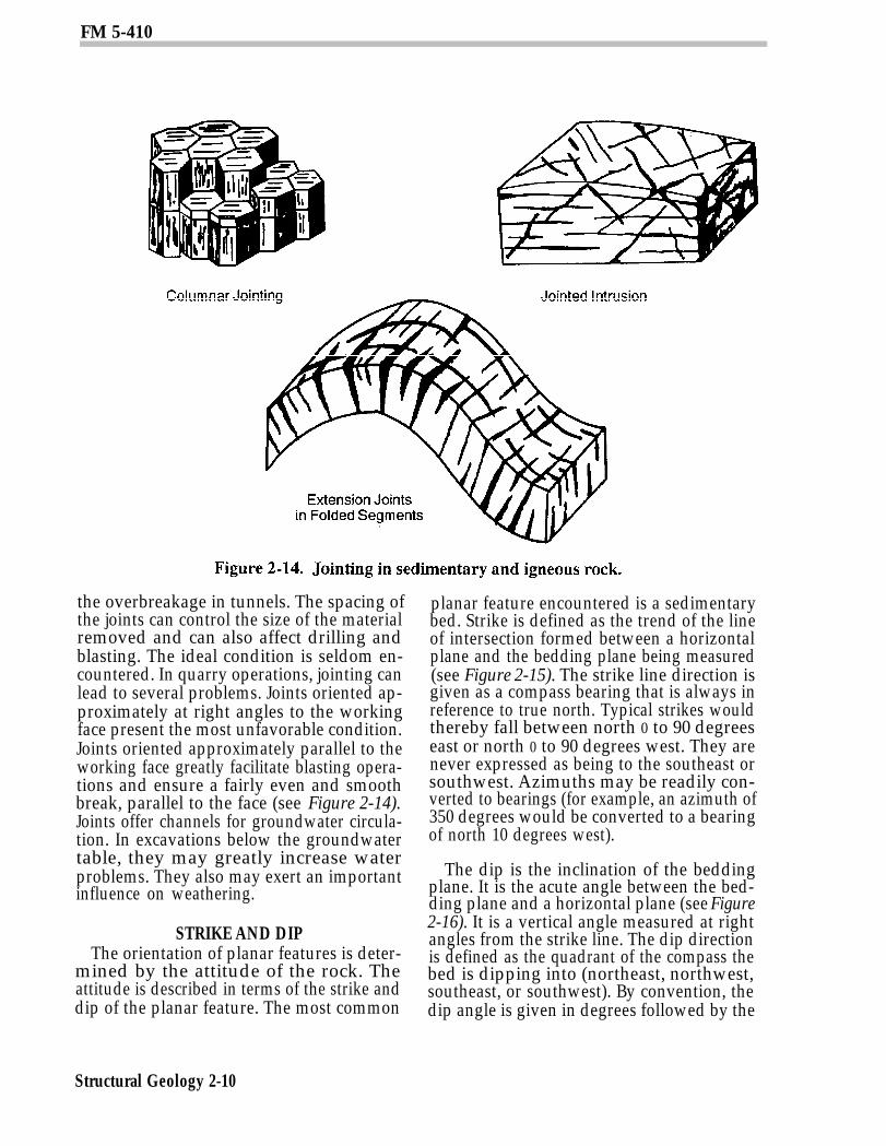
that there is little or no displacement parallelto the fractured surface are said to be jointed,and the fractures are called joints (see Figure2-14, page 2-10). Joints influence the way therock mass behaves when subjected to the
Structural Geology 2-8
FM 5-410
stresses of construction. Joints charac-teristically form planar surfaces. They mayhave any attitude; some are vertical, othersare horizontal, and many are inclined atvarious angles. Strike and dip are used tomeasure the attitude of joints. Some jointsmay occur as curved surfaces. Joints varygreatly in magnitude, from a few feet tothousands of feet long. They commonly occurin more or less parallel fractures called jointsets. Joint systems are two or more relatedjoint sets or any group of joints with a charac-teristic pattern, such as a radiating orconcentric pattern.
FormationJoints in rock masses may result from a
number of processes, including deformation,expansion, and contraction. In sedimentaryrocks, deformation during lithification or
folding may cause the formation of joints.Igneous rocks may contain joints formed aslava cooled and contracted. In dense, ex-trusive igneous rocks, like basalt, a form ofprismatic fracturing known as columnarjointing often develops as the rock cools rapidlyand shrinks. Jointing may also occur whenoverlying rock is removed by erosion, causinga rock mass to expand. This is known as ex-foliation. The outer layers of the rock peel,similar to the way that an onion does.
SignificanceBecause of their almost universal presence,
joints are of considerable engineering impor-tance, especially in excavation operations. Itis desirable for joints to be spaced closeenough to minimize secondary plugging andblasting requirements without impairing thestability of excavation slopes or increasing
Structural Geology 2-9
FM 5-410
the overbreakage in tunnels. The spacing ofthe joints can control the size of the materialremoved and can also affect drilling andblasting. The ideal condition is seldom en-countered. In quarry operations, jointing canlead to several problems. Joints oriented ap-proximately at right angles to the workingface present the most unfavorable condition.Joints oriented approximately parallel to theworking face greatly facilitate blasting opera-tions and ensure a fairly even and smoothbreak, parallel to the face (see Figure 2-14).Joints offer channels for groundwater circula-tion. In excavations below the groundwatertable, they may greatly increase waterproblems. They also may exert an importantinfluence on weathering.
STRIKE AND DIPThe orientation of planar features is deter-
mined by the attitude of the rock. Theattitude is described in terms of the strike anddip of the planar feature. The most common
planar feature encountered is a sedimentarybed. Strike is defined as the trend of the lineof intersection formed between a horizontalplane and the bedding plane being measured(see Figure 2-15). The strike line direction isgiven as a compass bearing that is always inreference to true north. Typical strikes wouldthereby fall between north 0 to 90 degreeseast or north 0 to 90 degrees west. They arenever expressed as being to the southeast orsouthwest. Azimuths may be readily con-verted to bearings (for example, an azimuth of350 degrees would be converted to a bearingof north 10 degrees west).
The dip is the inclination of the beddingplane. It is the acute angle between the bed-ding plane and a horizontal plane (see Figure2-16). It is a vertical angle measured at rightangles from the strike line. The dip directionis defined as the quadrant of the compass thebed is dipping into (northeast, northwest,southeast, or southwest). By convention, thedip angle is given in degrees followed by the
Structural Geology 2-10

FM 5-410
dip direction quadrant (for example, 30degrees northeast).
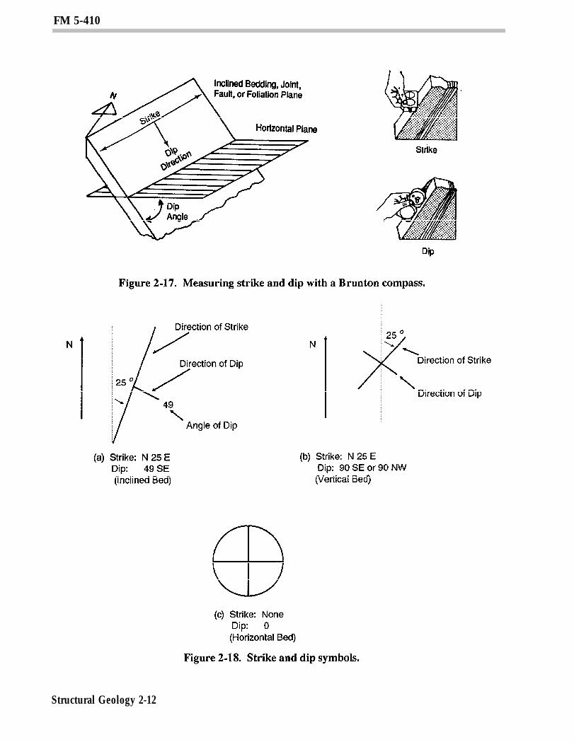
The strike and dip measurements aretaken in the field on rock outcrops with astandard Brunton compass. The Bruntoncompass is graduated in degrees and has abull’s-eye level for determining the horizontalplane when measuring the strike direction.The strike is determined by aligning the com-pass along the strike direction and readingthe value directly from the compass. In-cluded with the Brunton compass is aclinometer to measure the dip angle. Thisangle is measured by placing the edge of thecompass on the dipping surface at rightangles to the strike direction and reading theacute angle indicated by the clinometer (seeFigure 2-17, page 2-12).
Strike and dip symbols are used on geologicmaps and overlays to convey structural orien-tation. Basic symbols include those forinclined, vertical, and horizontal beds (seeFigure 2-18, page 2-12). For inclined beds,the direction of strike is designated as a longline that is oriented in reference to the mapgrid lines in exactly the same compass direc-tion as it was measured. The direction of thedip is represented by a short line that is al-ways drawn perpendicular to the strike lineand in the direction of the dip. The angle ofthe dip is written next to the symbol (see Fig-ure 2-18a, page 2-12). For vertical beds, the
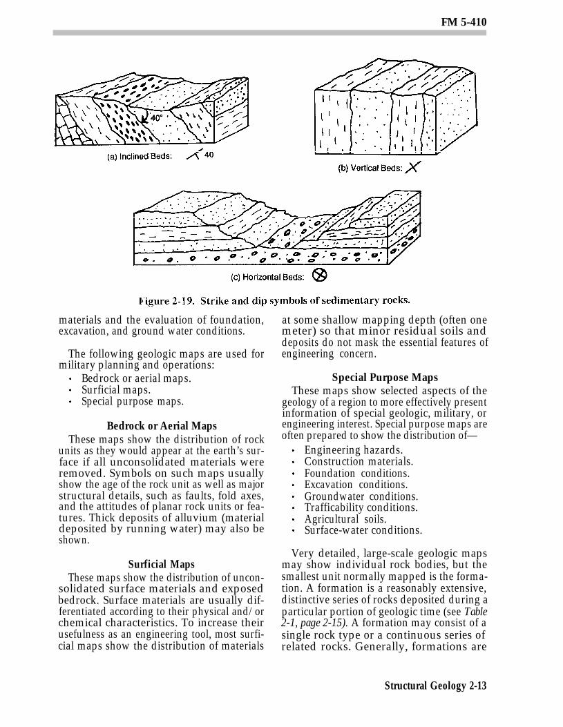
direction of the strike is designated as it is forinclined beds. The direction of the dip is ashort line crossing the strike line at a rightangle extending on both sides of the strikeline (see Figure 2-18b, page 2-12). Forhorizontal beds, the direction of strike is rep-resented by crossed lines which indicate thatthe rock strikes in every direction. The dip isrepresented by a circle encompassing thecrossed lines. The circle implies that there isno dip direction and the dip angle is zero (seeFigure 2-18c, page 2-12). These basic symbolsare commonly used to convey attitudes ofsedimentary rocks (see Figure 2-19, page2-13). Similar symbols are used to convey at-titudes of other types of planar features, suchas folds, faults, foliation, and jointing in otherrock bodies.
Section II. Geologic Maps
TYPESGeologic maps show the distribution of
geologic features and materials at the earth’ssurface. Most are prepared over topographicbase maps using aerial photography and fieldsurvey data. From a knowledge of geologicprocesses, the user of a geologic map can drawmany inferences as to the geologic relation-ships beneath the surface and also much ofthe geologic history of an area. In engineer-ing practice, geologic maps are importantguides to the location of construction
Structural Geology 2-11
FM 5-410
Structural Geology 2-12
FM 5-410
materials and the evaluation of foundation,excavation, and ground water conditions.
The following geologic maps are used formilitary planning and operations:
Bedrock or aerial maps.Surficial maps.Special purpose maps.
Bedrock or Aerial MapsThese maps show the distribution of rock
units as they would appear at the earth’s sur-face if all unconsolidated materials wereremoved. Symbols on such maps usuallyshow the age of the rock unit as well as majorstructural details, such as faults, fold axes,and the attitudes of planar rock units or fea-tures. Thick deposits of alluvium (materialdeposited by running water) may also beshown.
Surficial MapsThese maps show the distribution of uncon-
solidated surface materials and exposedbedrock. Surface materials are usually dif-ferentiated according to their physical and/orchemical characteristics. To increase theirusefulness as an engineering tool, most surfi-cial maps show the distribution of materials
at some shallow mapping depth (often onemeter) so that minor residual soils anddeposits do not mask the essential features ofengineering concern.
Special Purpose MapsThese maps show selected aspects of the
geology of a region to more effectively presentinformation of special geologic, military, orengineering interest. Special purpose maps areoften prepared to show the distribution of—
Engineering hazards.Construction materials.Foundation conditions.Excavation conditions.Groundwater conditions.Trafficability conditions.Agricultural soils.Surface-water conditions.
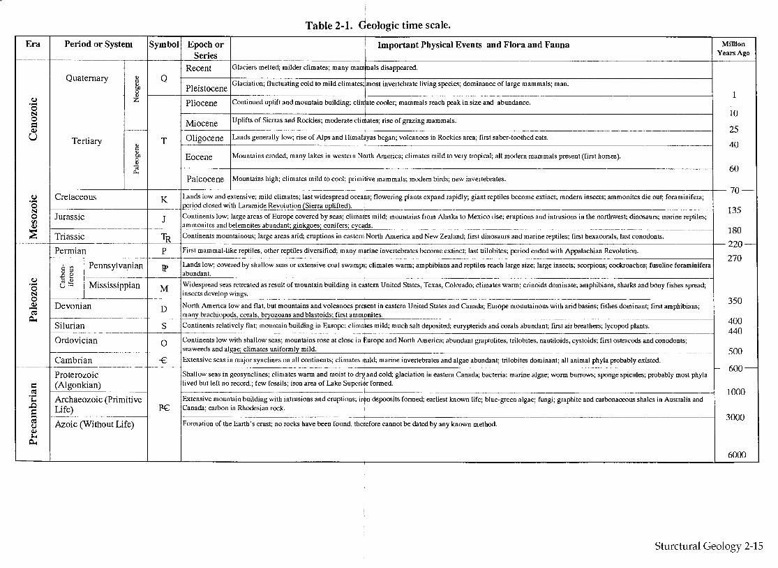
Very detailed, large-scale geologic mapsmay show individual rock bodies, but thesmallest unit normally mapped is the forma-tion. A formation is a reasonably extensive,distinctive series of rocks deposited during aparticular portion of geologic time (see Table2-1, page 2-15). A formation may consist of asingle rock type or a continuous series ofrelated rocks. Generally, formations are
Structural Geology 2-13
FM 5-410
named after the locality where they were firstdefined. Formations may be grouped by age,structure, or lithology for mapping purposes.
SYMBOLSSymbols are used to identify various fea-
tures on a geologic map. Some of thosefeatures are—
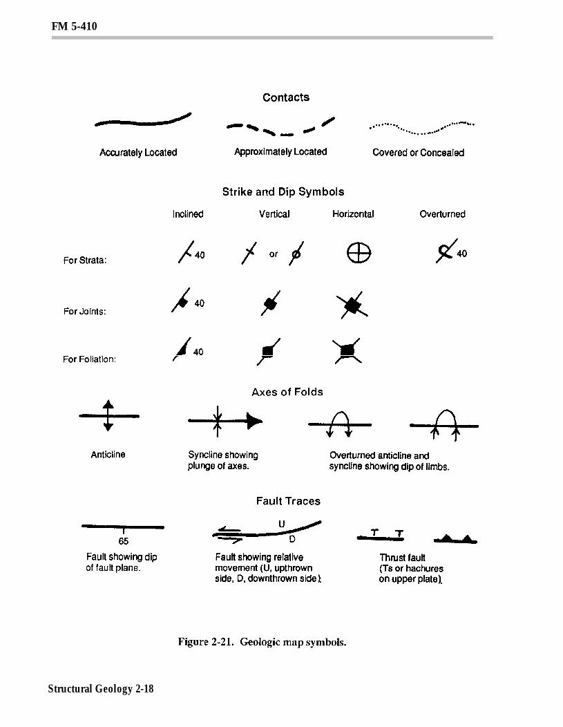
Formations (see Figure 2-21, page 2-18).Contacts (see Figure 2-21, page 2-18).Attitudes (see Figure 2-21, page 2-18).Fault lines and fold axes (see Figure2-21, page 2-18).Cross sections (see Figure 2-23, page2-19).
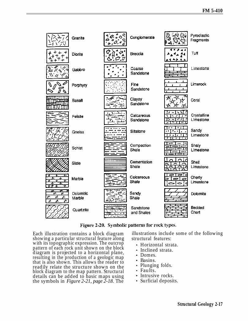
FormationsLetters, colors, or symbolic patterns are
used to distinguish formations or rock unitson a geologic map. These designators shouldbe defined in a legend on the map. Letter sym-bols usually consist of a capital letterindicating the period of deposition of the for-mation with subsequent letters (usuallylower case) that stand for the formal name ofthe unit, (see Table 2-1). Maps prepared by theUS Geological Survey and many other agen-cies use tints of yellow and orange forCenozoic rocks, tints of green for Mesozoicrocks, tints of blue and purple for Paleozoicrocks, and tints of red for Precambrian rocks,Symbolic patterns for various rock types aregiven in Figure 2-20, page 2-17.
ContactsA thin, solid line shows contacts or boun-
daries between rock units if the boundariesare accurately located. A dashed line is usedfor an approximate location and a dotted lineif the cointact, is covered or concealed. Ques-tionable or gradational contacts are shown bya dashed or dotted line with question marks.
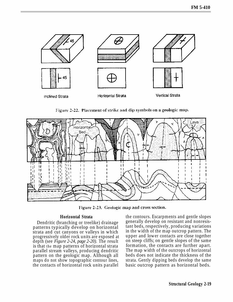
AttitudesStrike and dip symbols describe planes of
stratification, faulting, and jointing. Thesesymbols consist of a strike line long enough sothat its bearing can be determined from themap, a dip mark to indicate the dip directionof the plane being represented, and a number
to show the value (in degrees) of the dipangle. The number is omitted on repre-sentations of both horizontal and verticalbeds, because the values of the dips are auto-matically acknowledged to be 0 and 90 de-grees, respectively. Figure 2-22, page 2-19,shows the placement of strike and dip sym-bols on a geologic map with respect to the loca-tion and orientation of a sedimentary rockbed.
Fault Lines and Fold AxesHeavy black lines, which may be solid,
dashed, or dotted (as described for contacts),show fault lines and fold axes. The direc-tion of movement along faults is shown byarrows or by the use of symbols to indicateup thrown and down thrown sides. Thearrows accompanying fold axes indicatethe dip direction of the limbs and/or theplunge direction of the fold.
Cross SectionsCross sections show the distribution of
geologic features and materials in a verticalplane along a line on a map. Cross sectionsare prepared in much the same way astopographic profiles using map, field, andborehole data. Geologic sections accompanymany geologic maps to clarify subsurfacerelationships, Like geologic maps, geologicsections are often highly interpretive, espe-cially where data is limited and structuresare complex or concealed by overburden.Maps and sections use similar symbols andconventions. Because of the wealth of datathat can be shown, geologic maps and sectionsare the two most important means of record-ing and communicating geologic information.
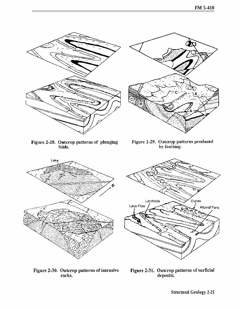
OUTCROP PATTERNSAn outcrop is that part of a rock formation
that is exposed at the earth’s surface. Out-crops are located where there is no existingsoil cover or where the soil has been removed,leaving the rock beneath it exposed. Outcropsmay indicate both the type and the structureof the local bedrock. Major types of structuralfeatures can be easily recognized on geologicmaps because of the distinctive patterns theyproduce. Figures 2-24 through 2-31, pages2-20 through 2-21, show basic examples ofcommon structural patterns.
Structural Geology 2-14

FM 5-410
Structural Geology 2-16
FM 5-410
Each illustration contains a block diagram illustrations include some of the followingstructural features:
Horizontal strata.Inclined strata.Domes.Basins.Plunging folds.Faults.Intrusive rocks.Surficial deposits.
showing a particular structural feature alongwith its topographic expression. The outcroppattern of each rock unit shown on the blockdiagram is projected to a horizontal plane,resulting in the production of a geologic mapthat is also shown. This allows the reader toreadily relate the structure shown on theblock diagram to the map pattern. Structuraldetails can be added to basic maps usingthe symbols in Figure 2-21, page 2-18. The
Structural Geology 2-17
FM 5-410
Structural Geology 2-18
FM 5-410
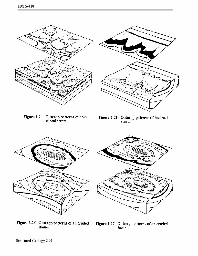
Horizontal StrataDendritic (branching or treelike) drainage
patterns typically develop on horizontalstrata and cut canyons or valleys in whichprogressively older rock units are exposed atdepth (see Figure 2-24, page 2-20). The resultis that the map patterns of horizontal strataparallel stream valleys, producing dendriticpattern on the geologic map. Although allmaps do not show topographic contour lines,the contacts of horizontal rock units parallel
the contours. Escarpments and gentle slopesgenerally develop on resistant and nonresis-tant beds, respectively, producing variationsin the width of the map outcrop pattern. Theupper and lower contacts are close togetheron steep cliffs; on gentle slopes of the sameformation, the contacts are further apart.The map width of the outcrops of horizontalbeds does not indicate the thickness of thestrata. Gently dipping beds develop the samebasic outcrop pattern as horizontal beds.
Structural Geology 2-19
FM 5-410
Structural Geology 2-20
FM 5-410
Structural Geology 2-21
FM 5-410
However, the contacts of gently dippingstrata, if traced far enough up a valley, crosstopographic contours and form a large V-shaped pattern that points in the directionthe beds dip, assuming that the beds do not,dip in the direction of the stream gradient,but at a smaller angle.
Inclined StrataWhen a sequence of rocks is tilted and cut
off by erosion, the outcrop pattern ap-pears as bands that, on a regional basis, areroughly parallel. Where dipping strata crossa valley, they produce a V-shaped outcroppattern that points in the direction of dip, ex-cept in cases where the beds dip in thedirection of the stream gradient at smallerangles than the gradient. The size of the V isinversely proportional to the degree of dip.
Low-angle dip (large V) (see frontpart of Figure 2-25, page 2-20).High-angle dip (small V).Vertical dip (no V) (see back part ofFigure 2-25, page 2-20).
Other relationships that are basic to the in-terpretation of geologic maps are also shownin Figure 2-25, page 2-20. For example, theyshow that older beds dip toward youngerbeds unless the sequence has been over-turned (as by folding or faulting). Maps alsoshow that outcrop width depends on thethickness of the beds, the dip of the beds (lowdip, maximum width), and the slope of thetopography (steep slope, minimum width).
DomesEroded dome-shaped structures form a
roughly circular outcrop pattern with bedsdipping away from a central area in which theoldest rocks outcrop (see Figure 2-26, page2-20). These structures range from small fea-tures only a few meters across to greatUpwarps covering areas of hundreds orthousands of square kilometers.
Drainage patterns are helpful in interpret-ing a domal structure. Radial drainagepatterns tend to form on domes. Streams cut-ting across the resistant beds permit one to
apply the “rule of Vs” as explained above tointerpret the direction of dip.
BasinsEroded structural basins form an outcrop
pattern very similar to that of an eroded dome(see Figure 2-27, page 2-20). However, twomajor features serve to distinguish them:younger rocks outcrop in the center of a basinand, if the structure has been dissected bystream erosion, the outcrop Vs normally pointtoward the center of a basin, whereas theyusually point away from the center of a dome.
Plunging FoldsFolding is found in complex mountain
ranges and sometimes in lowlands andplateaus. When folds erode, the oldest rocksoutcrop in the center of the anticlines (or up-folds) and the youngest rocks outcrop in thecenter of the synclines (or downfolds). Theaxes of folded beds are horizontal in somefolds, but they are usually inclined. In thiscase, the fold is said to plunge. Plunging foldsform a characteristic zigzag outcrop patternwhen eroded (see Figure 2-28, page 2-21). Aplunging anticline forms a V-shaped patternwith the apex (or nose) of the V pointing in thedirection of the plunge. Plunging synclinesform a similar pattern, but the limbs of thefold open in the direction of the plunge.
FaultsFault patterns on geologic maps are distinc-
tive in that they abruptly offset structuresand terminate contacts (see Figure 2-29,page 2-21). They are expressed on the geologicmap by heavy lines in order to be readilydistinguished. Some common types are–
Normal.Reverse.Thrust.
Normal and Reverse (see A and B, respec-tively, in Figure 2-29, page 2-21). Both normaland reverse fault planes generally dip at ahigh angle, so outcrop patterns are relativelystraight. Older rocks are usually exposed onthe upthrown block. It is thus possible todetermine the relative movement on most
Structural Geology 2-22
FM 5-410
high-angle faults from map relationsalone. Linear streams, offsets, linear scarps,straight valleys, linear-trending springs orponds, and omitted or repeated strata arecommon indications of faulting (see para-graph on recognition of faults, page 2-7).
Thrust (see C in Figure 2-29, page 2-21).Thrust faults are reverse faults that dip atlow angles (less than 15 degrees) and havestrati graphic displacements, commonlymeasured in kilometers (see Figure 2-10, page2-8). The trace of the thrust commonly formsVs where it intersects the valleys. The Vspoint in the direction of the fault plane dip,except in cases where the fault plane dips inthe direction of the stream gradient, but asmaller angle. Erosion may form windows(fensters) through the thrust sheet so that un-derlying rocks are exposed or produceisolation remnants (klippen) above the un-derlying rocks. Hachure symbols are used todesignate the overthrust block that usuallycontains the oldest rocks.
IntrusionsLarger igneous intrusions, such as
batholiths and stocks, are typically discor-dant and appear on geologic maps as ellipticalor roughly circular areas that cut across thecontacts of surrounding formations (see Fig-ure 2-30, page 2-21). Smaller discordantintrusions, such as dikes, are usually tabularand appear on geologic maps as straight,usually short, bands. However, some dikesare lenticular and appear as such on the map.Concordant intrusions, such as sills and lac-coliths, have contacts that parallel those ofthe surrounding formations (see Figure 1-5,page 1-7).
The relative age of igneous bodies can berecognized from crosscutting relationships.The younger intrusions cut the older ones.With this in mind, it is clear from the relation-ships in Figure 2-30, page 2-21, that theelliptical stock is the oldest intrusion, thenortheast trending dike the next oldest, andthe northwest trending dike the youngest.The age of the small discontinuous dikes nearthe western part of the map is younger than
that of the stock, but the age relation withthe other dikes is not indicated.
Surficial DepositsSurficial deposits are recent accumulations
of various types of sediment or volcanic debrison the surface of the landscape (see Figure2-31, page 2-21). The primary types are—
Windblown sand and loess.Stream channel and floodplain deposits.Landslide deposits.Glacial deposits.Present beaches and other shorelinesediments.
Section III. EngineeringConsiderations
ROCK DISTRIBUTIONGeologic structure controls the distribution
of rock bodies and features along and beneaththe earth’s surface. The presence and orienta-tion of such features as bedding, folding,faulting, and unconformities must be deter-mined before construction begins. Otherwise,foundation, excavation, and groundwater con-ditions cannot be properly evaluated.
ROCK FRAGMENTATIONRocks tend to fracture along existing zones
of weakness. The presence and spacing ofbedding, foliation, and joint planes can con-trol the size and shape of rock fragmentsproduced in quarries and other excavations.Operational and production costs may beprohibitive if rock fragments are too large, toosmall, too slabby, or too irregular for ag-gregate requirements. Advantageous joint orbedding spacings can significantly reduce ex-cavation and aggregate production costs.
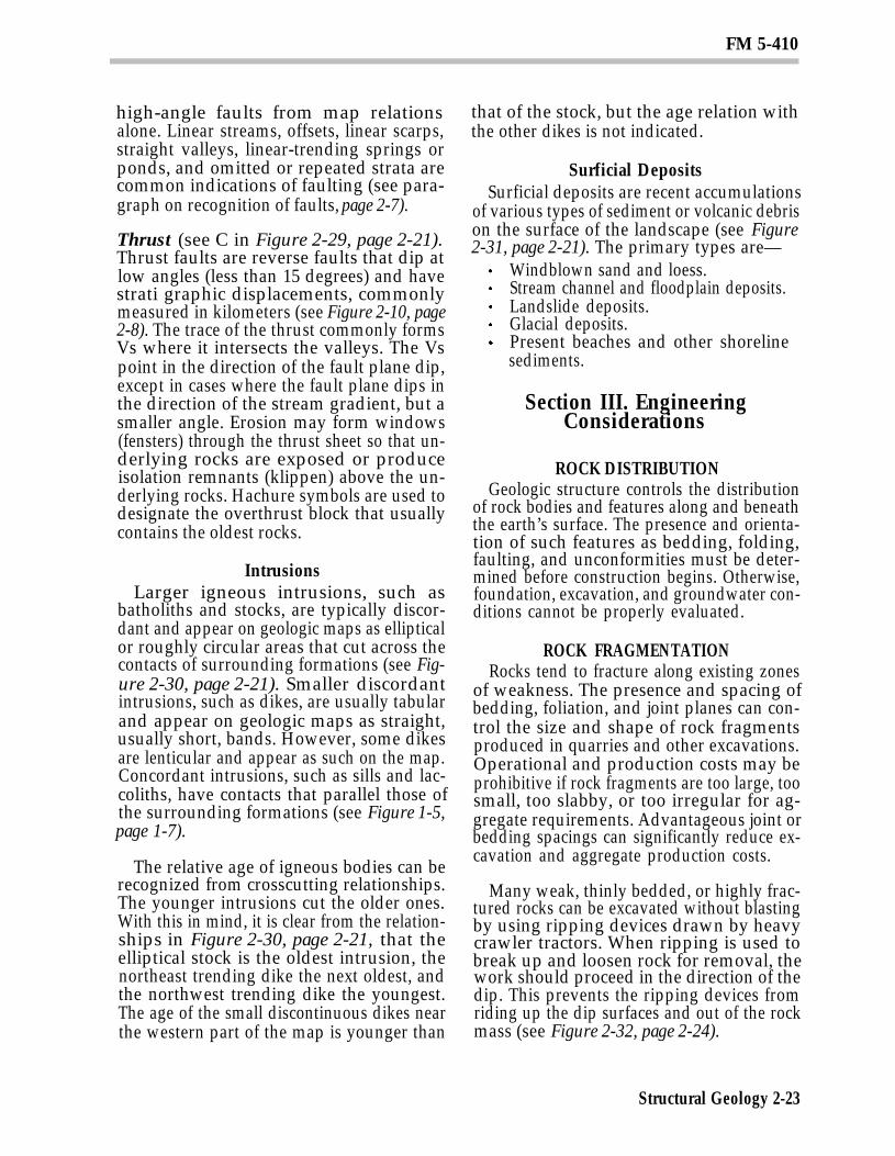
Many weak, thinly bedded, or highly frac-tured rocks can be excavated without blastingby using ripping devices drawn by heavycrawler tractors. When ripping is used tobreak up and loosen rock for removal, thework should proceed in the direction of thedip. This prevents the ripping devices fromriding up the dip surfaces and out of the rockmass (see Figure 2-32, page 2-24).
Structural Geology 2-23
FM 5-410
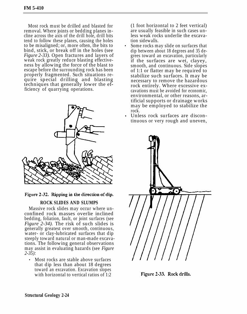
Most rock must be drilled and blasted forremoval. Where joints or bedding planes in-cline across the axis of the drill hole, drill bitstend to follow these planes, causing the holesto be misaligned; or, more often, the bits tobind, stick, or break off in the holes (seeFigure 2-33). Open fractures and layers ofweak rock greatly reduce blasting effective-ness by allowing the force of the blast toescape before the surrounding rock has beenproperly fragmented. Such situations re-quire special drilling and blastingtechniques that generally lower the ef-ficiency of quarrying operations.
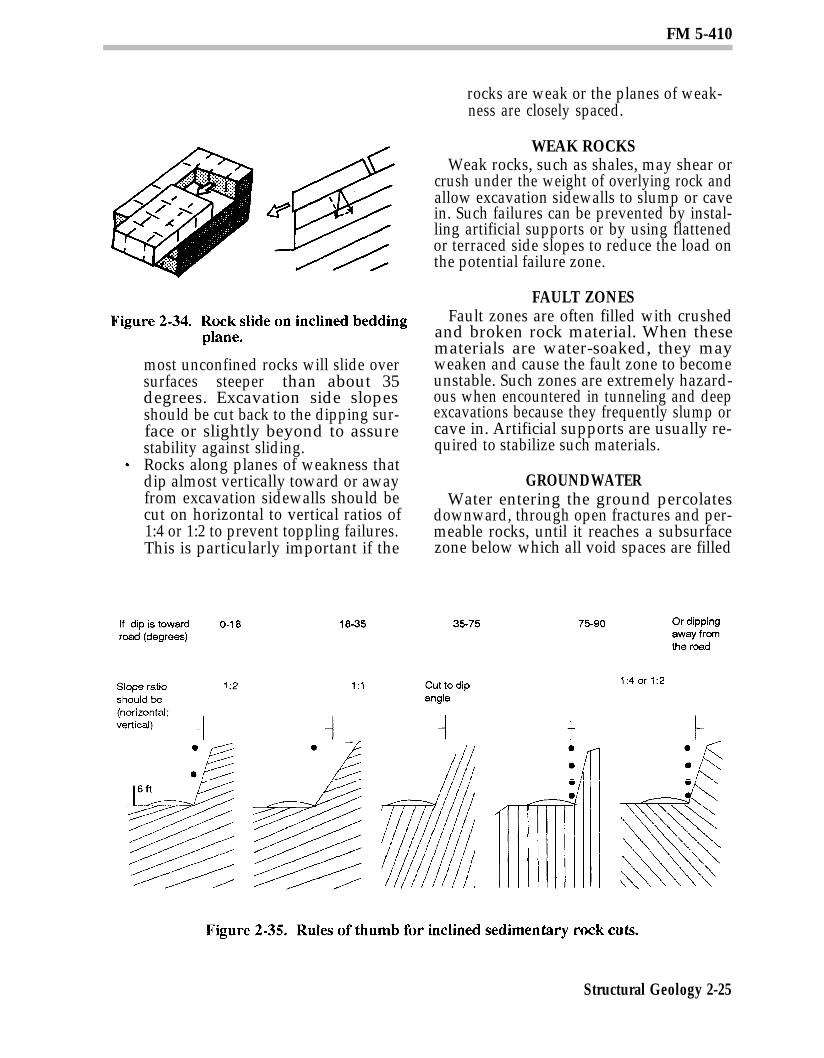
ROCK SLIDES AND SLUMPSMassive rock slides may occur where un-
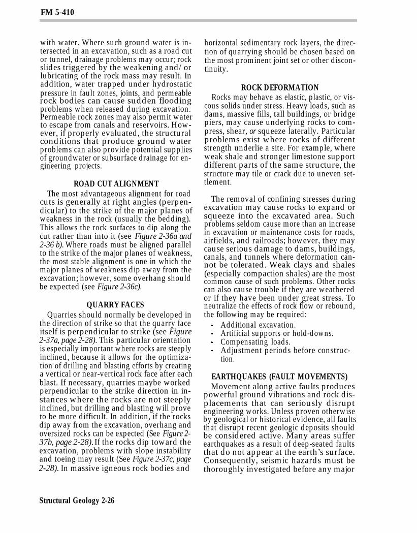
confined rock masses overlie inclinedbedding, foliation, fault, or joint surfaces (seeFigure 2-34). The risk of such slides isgenerally greatest over smooth, continuous,water- or clay-lubricated surfaces that dipsteeply toward natural or man-made excava-tions. The following general observationsmay assist in evaluating hazards (see Figure2-35):
Most rocks are stable above surfacesthat dip less than about 18 degreestoward an excavation. Excavation slopeswith horizontal to vertical ratios of 1:2
Structural Geology 2-24
(1 foot horizontal to 2 feet vertical)are usually feasible in such cases un-less weak rocks underlie the excava-tion sidewalls.Some rocks may slide on surfaces thatdip between about 18 degrees and 35 de-grees toward an excavation, particularlyif the surfaces are wet, clayey,smooth, and continuous. Side slopesof 1:1 or flatter may be required tostabilize such surfaces. It may benecessary to remove the hazardousrock entirely. Where excessive ex-cavations must be avoided for economic,environmental, or other reasons, ar-tificial supports or drainage worksmay be employed to stabilize therock.Unless rock surfaces are discon-tinuous or very rough and uneven,
FM 5-410
most unconfined rocks will slide oversurfaces steeper than about 35degrees. Excavation side slopesshould be cut back to the dipping sur-face or slightly beyond to assurestability against sliding.Rocks along planes of weakness thatdip almost vertically toward or awayfrom excavation sidewalls should becut on horizontal to vertical ratios of1:4 or 1:2 to prevent toppling failures.This is particularly important if the
rocks are weak or the planes of weak-ness are closely spaced.
WEAK ROCKSWeak rocks, such as shales, may shear or
crush under the weight of overlying rock andallow excavation sidewalls to slump or cavein. Such failures can be prevented by instal-ling artificial supports or by using flattenedor terraced side slopes to reduce the load onthe potential failure zone.
FAULT ZONESFault zones are often filled with crushed
and broken rock material. When thesematerials are water-soaked, they mayweaken and cause the fault zone to becomeunstable. Such zones are extremely hazard-ous when encountered in tunneling and deepexcavations because they frequently slump orcave in. Artificial supports are usually re-quired to stabilize such materials.
GROUNDWATERWater entering the ground percolates
downward, through open fractures and per-meable rocks, until it reaches a subsurfacezone below which all void spaces are filled
Structural Geology 2-25
FM 5-410
with water. Where such ground water is in-tersected in an excavation, such as a road cutor tunnel, drainage problems may occur; rockslides triggered by the weakening and/orlubricating of the rock mass may result. Inaddition, water trapped under hydrostaticpressure in fault zones, joints, and permeablerock bodies can cause sudden floodingproblems when released during excavation.Permeable rock zones may also permit waterto escape from canals and reservoirs. How-ever, if properly evaluated, the structuralconditions that produce ground waterproblems can also provide potential suppliesof groundwater or subsurface drainage for en-gineering projects.
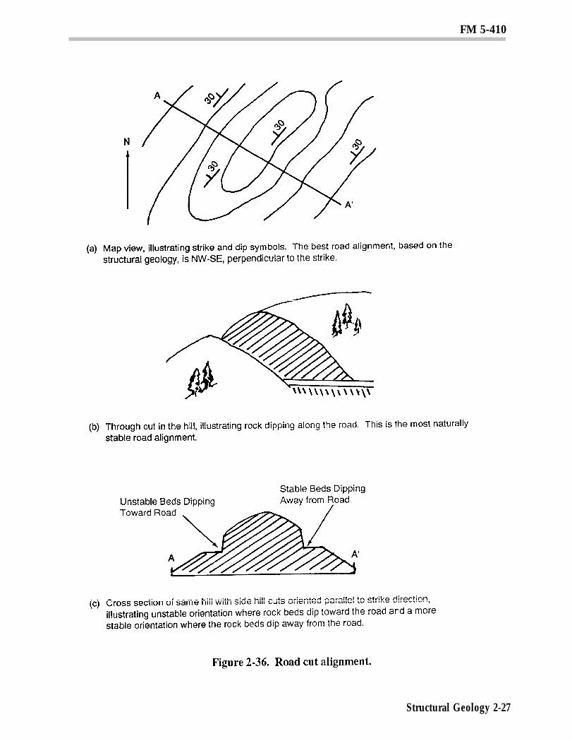
ROAD CUT ALIGNMENTThe most advantageous alignment for road
cuts is generally at right angles (perpen-dicular) to the strike of the major planes ofweakness in the rock (usually the bedding).This allows the rock surfaces to dip along thecut rather than into it (see Figure 2-36a and2-36 b). Where roads must be aligned parallelto the strike of the major planes of weakness,the most stable alignment is one in which themajor planes of weakness dip away from theexcavation; however, some overhang shouldbe expected (see Figure 2-36c).
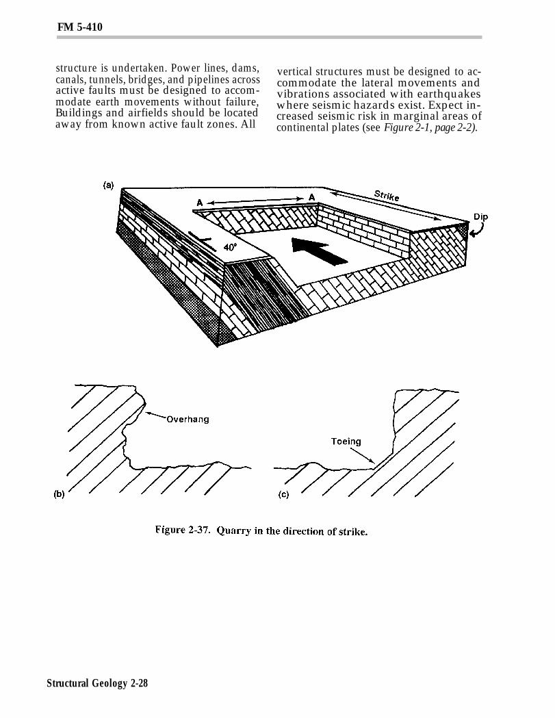
QUARRY FACESQuarries should normally be developed in
the direction of strike so that the quarry faceitself is perpendicular to strike (see Figure2-37a, page 2-28). This particular orientationis especially important where rocks are steeplyinclined, because it allows for the optimiza-tion of drilling and blasting efforts by creatinga vertical or near-vertical rock face after eachblast. If necessary, quarries maybe workedperpendicular to the strike direction in in-stances where the rocks are not steeplyinclined, but drilling and blasting will proveto be more difficult. In addition, if the rocksdip away from the excavation, overhang andoversized rocks can be expected (See Figure 2-37b, page 2-28). If the rocks dip toward theexcavation, problems with slope instabilityand toeing may result (See Figure 2-37c, page2-28). In massive igneous rock bodies and
Structural Geology 2-26
horizontal sedimentary rock layers, the direc-tion of quarrying should be chosen based onthe most prominent joint set or other discon-tinuity.
ROCK DEFORMATIONRocks may behave as elastic, plastic, or vis-
cous solids under stress. Heavy loads, such asdams, massive fills, tall buildings, or bridgepiers, may cause underlying rocks to com-press, shear, or squeeze laterally. Particularproblems exist where rocks of differentstrength underlie a site. For example, whereweak shale and stronger limestone supportdifferent parts of the same structure, thestructure may tile or crack due to uneven set-tlement.
The removal of confining stresses duringexcavation may cause rocks to expand orsqueeze into the excavated area. Suchproblems seldom cause more than an increasein excavation or maintenance costs for roads,airfields, and railroads; however, they maycause serious damage to dams, buildings,canals, and tunnels where deformation can-not be tolerated. Weak clays and shales(especially compaction shales) are the mostcommon cause of such problems. Other rockscan also cause trouble if they are weatheredor if they have been under great stress. Toneutralize the effects of rock flow or rebound,the following may be required:
Additional excavation.Artificial supports or hold-downs.Compensating loads.Adjustment periods before construc-tion.
EARTHQUAKES (FAULT MOVEMENTS)Movement along active faults produces
powerful ground vibrations and rock dis-placements that can seriously disruptengineering works. Unless proven otherwiseby geological or historical evidence, all faultsthat disrupt recent geologic deposits shouldbe considered active. Many areas sufferearthquakes as a result of deep-seated faultsthat do not appear at the earth’s surface.Consequently, seismic hazards must bethoroughly investigated before any major
FM 5-410
Structural Geology 2-27
FM 5-410
structure is undertaken. Power lines, dams, vertical structures must be designed to ac-canals, tunnels, bridges, and pipelines across commodate the lateral movements andactive faults must be designed to accom- vibrations associated with earthquakesmodate earth movements without failure, where seismic hazards exist. Expect in-Buildings and airfields should be located creased seismic risk in marginal areas ofaway from known active fault zones. All continental plates (see Figure 2-1, page 2-2).
Structural Geology 2-28