Embed Size (px)
Citation preview
FM 3-25.26
9-1
PART TWOLAND NAVIGATION
CHAPTER 9NAVIGATION EQUIPMENT AND METHODS
Compasses are the primary navigation tools to use when moving in anoutdoor world where there is no other way to find directions. Soldiers shouldbe thoroughly familiar with the compass and its uses. Part One of thismanual discussed the techniques of map reading. To complement thesetechniques, a mastery of field movement techniques is essential. This chapterdescribes the lensatic compass and its uses, and some of the field expedientmethods used to find directions when compasses are not available.
9-1. TYPES OF COMPASSESThe lensatic compass is the most common and simplest instrument for measuring direction.It is discussed in detail in paragraph 9-2. The artillery M2 compass is a special-purposeinstrument designed for accuracy; it will be discussed in Appendix G. The wrist/pocketcompass is a small magnetic compass that can be attached to a wristwatch band. It containsa north-seeking arrow and a dial in degrees. A protractor can be used to determine azimuthswhen a compass is not available. However, it should be noted that when using the protractoron a map, only grid azimuths are obtained.
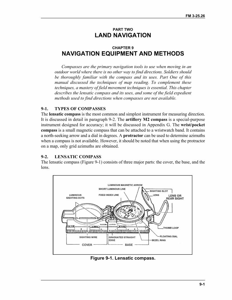
9-2. LENSATIC COMPASSThe lensatic compass (Figure 9-1) consists of three major parts: the cover, the base, and thelens.
Figure 9-1. Lensatic compass.
FM 3-25.26
9-2
a. Cover. The compass cover protects the floating dial. It contains the sighting wire(front sight) and two luminous sighting slots or dots used for night navigation.
b. Base. The body of the compass contains the following movable parts:(1) The floating dial is mounted on a pivot so it can rotate freely when the compass is
held level. Printed on the dial in luminous figures are an arrow and the letters E and W. Thearrow always points to magnetic north and the letters fall at east (E) 90° and west (W) 270°on the dial. There are two scales; the outer scale denotes mils and the inner scale (normallyin red) denotes degrees.
(2) Encasing the floating dial is a glass containing a fixed black index line.(3) The bezel ring is a ratchet device that clicks when turned. It contains 120 clicks when
rotated fully; each click is equal to 3°. A short luminous line that is used in conjunction withthe north-seeking arrow during navigation is contained in the glass face of the bezel ring.
(4) The thumb loop is attached to the base of the compass.c. Lens. The lens is used to read the dial, and it contains the rear-sight slot used in
conjunction with the front for sighting on objects. The rear sight also serves as a lock andclamps the dial when closed for its protection. The rear sight must be opened more than 45°to allow the dial to float freely.
NOTE: When opened, the straightedge on the left side of the compass has a coordinatescale; the scale is 1:50,000 in newer compasses.
WARNINGSome older compasses will have a 1:25,000 scale. This scale can be usedwith a 1:50,000-scale map, but the values read must be halved. Check thescale.
9-3. COMPASS HANDLINGCompasses are delicate instruments and should be cared for accordingly.
a. Inspection. A detailed inspection is required when first obtaining and using acompass. One of the most important parts to check is the floating dial, which contains themagnetic needle. The user must also make sure the sighting wire is straight, the glass andcrystal parts are not broken, the numbers on the dial are readable, and most important, thatthe dial does not stick.
b. Effects of Metal and Electricity. Metal objects and electrical sources can affect theperformance of a compass. However, nonmagnetic metals and alloys do not affect compassreadings. The following separation distances are suggested to ensure proper functioning ofa compass:
High-tension power lines ........................................55 meters.Field gun, truck, or tank ..........................................18 meters.Telegraph or telephone wires and barbed wire .......10 meters.Machine gun............................................................2 meters.Steel helmet or rifle .................................................1/2 meter.
c. Accuracy. A compass in good working condition is very accurate. However, acompass has to be checked periodically on a known line of direction, such as a surveyed
FM 3-25.26
9-3
azimuth using a declination station. Compasses with more than 3° + variation should not beused.
d. Protection. If traveling with the compass unfolded, make sure the rear sight is fullyfolded down onto the bezel ring. This will lock the floating dial and prevent vibration, aswell as protect the crystal and rear sight from damage.
9-4. USING A COMPASSMagnetic azimuths are determined with the use of magnetic instruments, such as lensatic andM2 compasses. The techniques employed when using the lensatic compass are as follows:
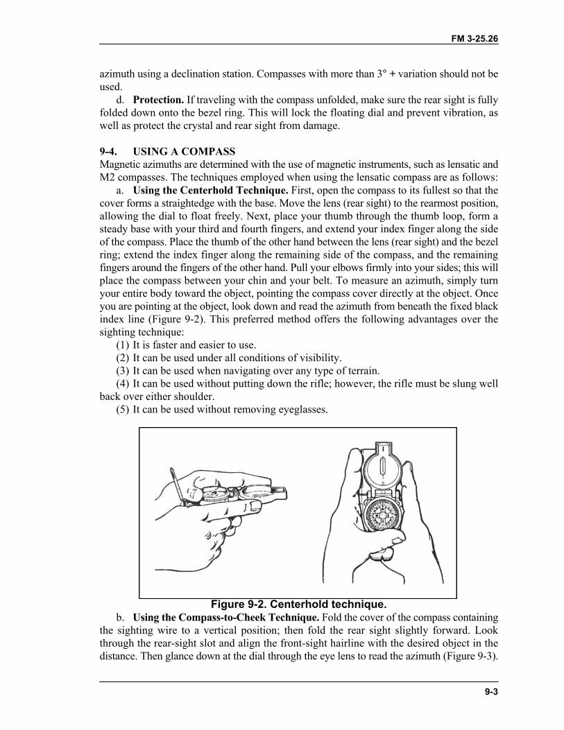
a. Using the Centerhold Technique. First, open the compass to its fullest so that thecover forms a straightedge with the base. Move the lens (rear sight) to the rearmost position,allowing the dial to float freely. Next, place your thumb through the thumb loop, form asteady base with your third and fourth fingers, and extend your index finger along the sideof the compass. Place the thumb of the other hand between the lens (rear sight) and the bezelring; extend the index finger along the remaining side of the compass, and the remainingfingers around the fingers of the other hand. Pull your elbows firmly into your sides; this willplace the compass between your chin and your belt. To measure an azimuth, simply turnyour entire body toward the object, pointing the compass cover directly at the object. Onceyou are pointing at the object, look down and read the azimuth from beneath the fixed blackindex line (Figure 9-2). This preferred method offers the following advantages over thesighting technique:
(1) It is faster and easier to use.(2) It can be used under all conditions of visibility.(3) It can be used when navigating over any type of terrain.(4) It can be used without putting down the rifle; however, the rifle must be slung well
back over either shoulder.(5) It can be used without removing eyeglasses.
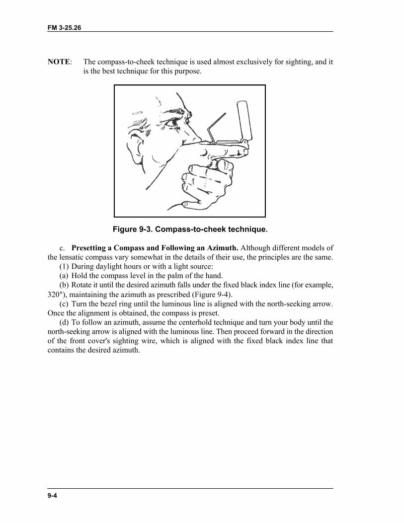
Figure 9-2. Centerhold technique.b. Using the Compass-to-Cheek Technique. Fold the cover of the compass containing
the sighting wire to a vertical position; then fold the rear sight slightly forward. Lookthrough the rear-sight slot and align the front-sight hairline with the desired object in thedistance. Then glance down at the dial through the eye lens to read the azimuth (Figure 9-3).
FM 3-25.26
9-4
NOTE: The compass-to-cheek technique is used almost exclusively for sighting, and itis the best technique for this purpose.
Figure 9-3. Compass-to-cheek technique.
c. Presetting a Compass and Following an Azimuth. Although different models ofthe lensatic compass vary somewhat in the details of their use, the principles are the same.
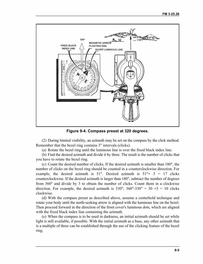
(1) During daylight hours or with a light source:(a) Hold the compass level in the palm of the hand.(b) Rotate it until the desired azimuth falls under the fixed black index line (for example,
320°), maintaining the azimuth as prescribed (Figure 9-4).(c) Turn the bezel ring until the luminous line is aligned with the north-seeking arrow.
Once the alignment is obtained, the compass is preset.(d) To follow an azimuth, assume the centerhold technique and turn your body until the
north-seeking arrow is aligned with the luminous line. Then proceed forward in the directionof the front cover's sighting wire, which is aligned with the fixed black index line thatcontains the desired azimuth.
FM 3-25.26
9-5
Figure 9-4. Compass preset at 320 degrees.
(2) During limited visibility, an azimuth may be set on the compass by the click method.Remember that the bezel ring contains 3° intervals (clicks).
(a) Rotate the bezel ring until the luminous line is over the fixed black index line.(b) Find the desired azimuth and divide it by three. The result is the number of clicks that
you have to rotate the bezel ring.(c) Count the desired number of clicks. If the desired azimuth is smaller than 180°, the
number of clicks on the bezel ring should be counted in a counterclockwise direction. Forexample, the desired azimuth is 51°. Desired azimuth is 51°÷ 3 = 17 clickscounterclockwise. If the desired azimuth is larger than 180°, subtract the number of degreesfrom 360° and divide by 3 to obtain the number of clicks. Count them in a clockwisedirection. For example, the desired azimuth is 330°; 360°-330° = 30 ÷3 = 10 clicksclockwise.
(d) With the compass preset as described above, assume a centerhold technique androtate your body until the north-seeking arrow is aligned with the luminous line on the bezel.Then proceed forward in the direction of the front cover's luminous dots, which are alignedwith the fixed black index line containing the azimuth.
(e) When the compass is to be used in darkness, an initial azimuth should be set whilelight is still available, if possible. With the initial azimuth as a base, any other azimuth thatis a multiple of three can be established through the use of the clicking feature of the bezelring.
FM 3-25.26
9-6
NOTE: Sometimes the desired azimuth is not exactly divisible by three, causing an optionof rounding up or rounding down. If the azimuth is rounded up, this causes anincrease in the value of the azimuth, and the object is to be found on the left. Ifthe azimuth is rounded down, this causes a decrease in the value of the azimuth,and the object is to be found on the right.
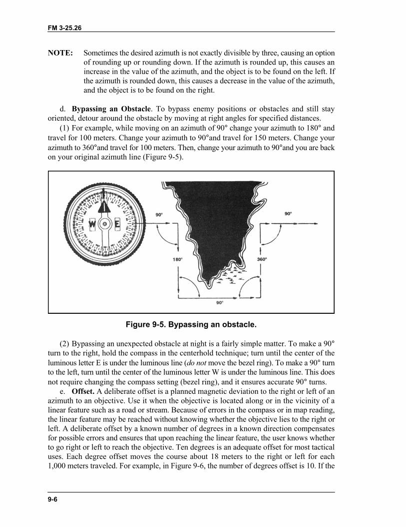
d. Bypassing an Obstacle. To bypass enemy positions or obstacles and still stayoriented, detour around the obstacle by moving at right angles for specified distances.
(1) For example, while moving on an azimuth of 90° change your azimuth to 180° andtravel for 100 meters. Change your azimuth to 90°and travel for 150 meters. Change yourazimuth to 360°and travel for 100 meters. Then, change your azimuth to 90°and you are backon your original azimuth line (Figure 9-5).
Figure 9-5. Bypassing an obstacle.
(2) Bypassing an unexpected obstacle at night is a fairly simple matter. To make a 90°turn to the right, hold the compass in the centerhold technique; turn until the center of theluminous letter E is under the luminous line (do not move the bezel ring). To make a 90° turnto the left, turn until the center of the luminous letter W is under the luminous line. This doesnot require changing the compass setting (bezel ring), and it ensures accurate 90° turns.
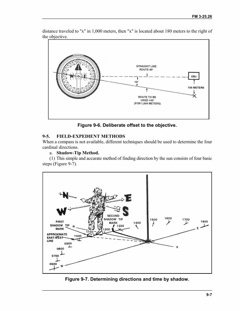
e. Offset. A deliberate offset is a planned magnetic deviation to the right or left of anazimuth to an objective. Use it when the objective is located along or in the vicinity of alinear feature such as a road or stream. Because of errors in the compass or in map reading,the linear feature may be reached without knowing whether the objective lies to the right orleft. A deliberate offset by a known number of degrees in a known direction compensatesfor possible errors and ensures that upon reaching the linear feature, the user knows whetherto go right or left to reach the objective. Ten degrees is an adequate offset for most tacticaluses. Each degree offset moves the course about 18 meters to the right or left for each1,000 meters traveled. For example, in Figure 9-6, the number of degrees offset is 10. If the
FM 3-25.26
9-7
distance traveled to "x" in 1,000 meters, then "x" is located about 180 meters to the right ofthe objective.
Figure 9-6. Deliberate offset to the objective.
9-5. FIELD-EXPEDIENT METHODSWhen a compass is not available, different techniques should be used to determine the fourcardinal directions.
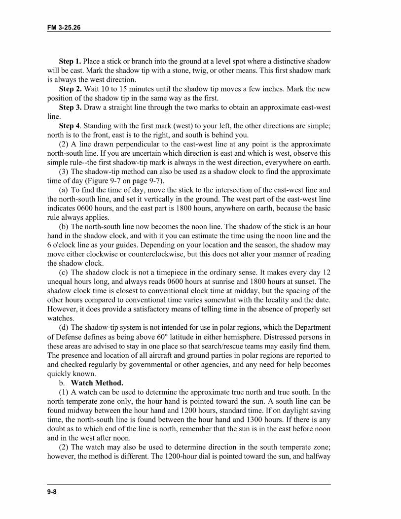
a. Shadow-Tip Method.(1) This simple and accurate method of finding direction by the sun consists of four basic
steps (Figure 9-7).
Figure 9-7. Determining directions and time by shadow.
FM 3-25.26
9-8
Step 1. Place a stick or branch into the ground at a level spot where a distinctive shadowwill be cast. Mark the shadow tip with a stone, twig, or other means. This first shadow markis always the west direction.
Step 2. Wait 10 to 15 minutes until the shadow tip moves a few inches. Mark the newposition of the shadow tip in the same way as the first.
Step 3. Draw a straight line through the two marks to obtain an approximate east-westline.
Step 4. Standing with the first mark (west) to your left, the other directions are simple;north is to the front, east is to the right, and south is behind you.
(2) A line drawn perpendicular to the east-west line at any point is the approximatenorth-south line. If you are uncertain which direction is east and which is west, observe thissimple rule--the first shadow-tip mark is always in the west direction, everywhere on earth.
(3) The shadow-tip method can also be used as a shadow clock to find the approximatetime of day (Figure 9-7 on page 9-7).
(a) To find the time of day, move the stick to the intersection of the east-west line andthe north-south line, and set it vertically in the ground. The west part of the east-west lineindicates 0600 hours, and the east part is 1800 hours, anywhere on earth, because the basicrule always applies.
(b) The north-south line now becomes the noon line. The shadow of the stick is an hourhand in the shadow clock, and with it you can estimate the time using the noon line and the6 o'clock line as your guides. Depending on your location and the season, the shadow maymove either clockwise or counterclockwise, but this does not alter your manner of readingthe shadow clock.
(c) The shadow clock is not a timepiece in the ordinary sense. It makes every day 12unequal hours long, and always reads 0600 hours at sunrise and 1800 hours at sunset. Theshadow clock time is closest to conventional clock time at midday, but the spacing of theother hours compared to conventional time varies somewhat with the locality and the date.However, it does provide a satisfactory means of telling time in the absence of properly setwatches.
(d) The shadow-tip system is not intended for use in polar regions, which the Departmentof Defense defines as being above 60° latitude in either hemisphere. Distressed persons inthese areas are advised to stay in one place so that search/rescue teams may easily find them.The presence and location of all aircraft and ground parties in polar regions are reported toand checked regularly by governmental or other agencies, and any need for help becomesquickly known.
b. Watch Method.(1) A watch can be used to determine the approximate true north and true south. In the
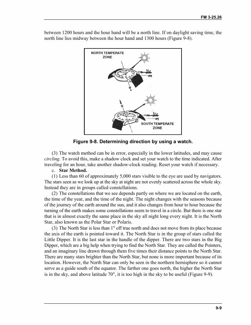
north temperate zone only, the hour hand is pointed toward the sun. A south line can befound midway between the hour hand and 1200 hours, standard time. If on daylight savingtime, the north-south line is found between the hour hand and 1300 hours. If there is anydoubt as to which end of the line is north, remember that the sun is in the east before noonand in the west after noon.
(2) The watch may also be used to determine direction in the south temperate zone;however, the method is different. The 1200-hour dial is pointed toward the sun, and halfway
FM 3-25.26
9-9
between 1200 hours and the hour hand will be a north line. If on daylight saving time, thenorth line lies midway between the hour hand and 1300 hours (Figure 9-8).
Figure 9-8. Determining direction by using a watch.
(3) The watch method can be in error, especially in the lower latitudes, and may causecircling. To avoid this, make a shadow clock and set your watch to the time indicated. Aftertraveling for an hour, take another shadow-clock reading. Reset your watch if necessary.
c. Star Method.(1) Less than 60 of approximately 5,000 stars visible to the eye are used by navigators.
The stars seen as we look up at the sky at night are not evenly scattered across the whole sky.Instead they are in groups called constellations.
(2) The constellations that we see depends partly on where we are located on the earth,the time of the year, and the time of the night. The night changes with the seasons becauseof the journey of the earth around the sun, and it also changes from hour to hour because theturning of the earth makes some constellations seem to travel in a circle. But there is one starthat is in almost exactly the same place in the sky all night long every night. It is the NorthStar, also known as the Polar Star or Polaris.
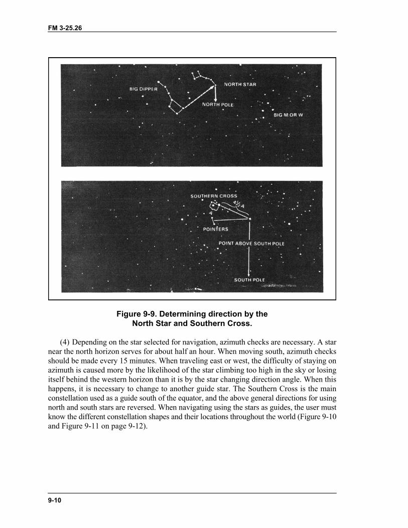
(3) The North Star is less than 1° off true north and does not move from its place becausethe axis of the earth is pointed toward it. The North Star is in the group of stars called theLittle Dipper. It is the last star in the handle of the dipper. There are two stars in the BigDipper, which are a big help when trying to find the North Star. They are called the Pointers,and an imaginary line drawn through them five times their distance points to the North Star.There are many stars brighter than the North Star, but none is more important because of itslocation. However, the North Star can only be seen in the northern hemisphere so it cannotserve as a guide south of the equator. The farther one goes north, the higher the North Staris in the sky, and above latitude 70°, it is too high in the sky to be useful (Figure 9-9).
FM 3-25.26
9-10
Figure 9-9. Determining direction by theNorth Star and Southern Cross.
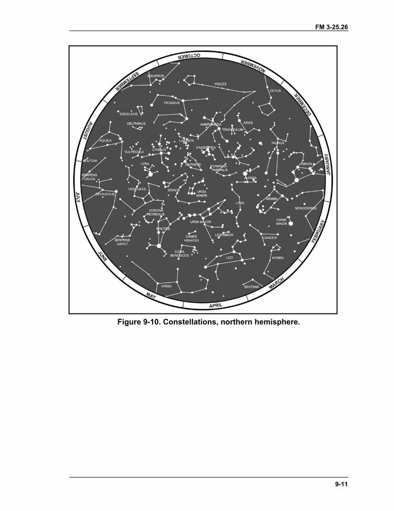
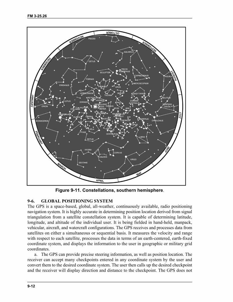
(4) Depending on the star selected for navigation, azimuth checks are necessary. A starnear the north horizon serves for about half an hour. When moving south, azimuth checksshould be made every 15 minutes. When traveling east or west, the difficulty of staying onazimuth is caused more by the likelihood of the star climbing too high in the sky or losingitself behind the western horizon than it is by the star changing direction angle. When thishappens, it is necessary to change to another guide star. The Southern Cross is the mainconstellation used as a guide south of the equator, and the above general directions for usingnorth and south stars are reversed. When navigating using the stars as guides, the user mustknow the different constellation shapes and their locations throughout the world (Figure 9-10and Figure 9-11 on page 9-12).
FM 3-25.26
9-11
Figure 9-10. Constellations, northern hemisphere.
FM 3-25.26
9-12
Figure 9-11. Constellations, southern hemisphere.
9-6. GLOBAL POSITIONING SYSTEMThe GPS is a space-based, global, all-weather, continuously available, radio positioningnavigation system. It is highly accurate in determining position location derived from signaltriangulation from a satellite constellation system. It is capable of determining latitude,longitude, and altitude of the individual user. It is being fielded in hand-held, manpack,vehicular, aircraft, and watercraft configurations. The GPS receives and processes data fromsatellites on either a simultaneous or sequential basis. It measures the velocity and rangewith respect to each satellite, processes the data in terms of an earth-centered, earth-fixedcoordinate system, and displays the information to the user in geographic or military gridcoordinates.
a. The GPS can provide precise steering information, as well as position location. Thereceiver can accept many checkpoints entered in any coordinate system by the user andconvert them to the desired coordinate system. The user then calls up the desired checkpointand the receiver will display direction and distance to the checkpoint. The GPS does not
FM 3-25.26
9-13
have inherent drift, an improvement over the Inertial Navigation System, and the receiverwill automatically update its position. The receiver can also compute time to the nextcheckpoint.
b. Specific uses for the GPS are position location; navigation; weapon location; targetand sensor location; coordination of firepower; scout and screening operations; combatresupply; location of obstacles, barriers, and gaps; and communication support. The GPSalso has the potential to allow units to train their soldiers and provide the following:
• Performance feedback.• Knowledge of routes taken by the soldier.• Knowledge of errors committed by the soldier.• Comparison of planned versus executed routes.• Safety and control of lost and injured soldiers.
(See Appendix J for more information of the GPS.)