Embed Size (px)
Citation preview
MHICopy 3
DEPARTMENT OF THE ARMY FIELD MANUAL
~ -
U. S. RIFLE7.62-MM
M14
RESCINDEDFOR HISTDRICAl USE ONLY
HEADQUARTERS, DEPARTMENT OF THE ARMYDECEMBER 1959
AGO 2766B-Def
FM 23-8C'
FIELD MANUAL
U.S. RIFLE, 7.62-MM, M14
FM 23-8 HEADQUIARTE'I'RS,D)EI'ARTMJIENT OF' Tl'' ARIMY
CIIANES No. 1 \NA.srHlNGTo- 2'5. D.C.. 20 JMa 1960
FM 23-S, 7 Decemlnber 1959, is changed as follows:
1. Purpose and Scope
b. Marksmanship training is covered in FM 2:--5. FM 23-15, andFM 23-TI.
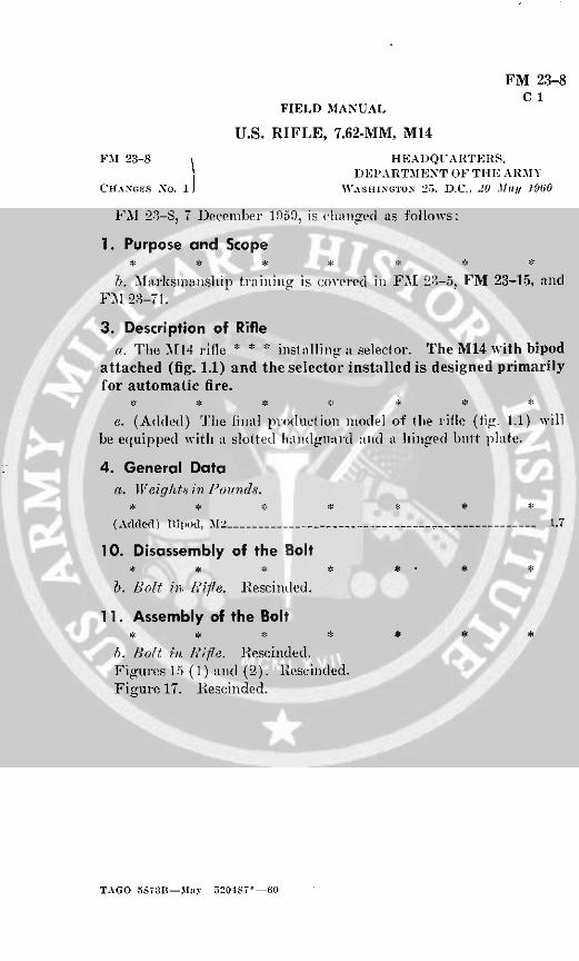
3. Description of Riflea. The M114 rifle * * * installin t a selector. The M14 with bipod
attached (fig. 1.1) and the selector installed is designed primarilyfor automatic fire.
e. (Added) The final production model of the rifle (fig. 1.1) willbe equipped with a slotted handgua: d and a hiiiged blitt plate.
4. General Dataa. lVeigltts in PI'oInds.
(Added) Blipod, M2 .................................- .1.7
10. Disassembly of the Bolt
b. Bolt inl ifle. Rescinded.
11. Assembly of the Bolt
b. Bolt in, l /ie. Rescinded.Figulres 15 (1) and (2). Rescinded.Figure 17. Rescinded.
TAGO 5S73B--3Iy 520487'--60

~~~~~~~~-i
A-
.4
D
12
2 TAGiO 5S-,3B

I' I
Ig ss
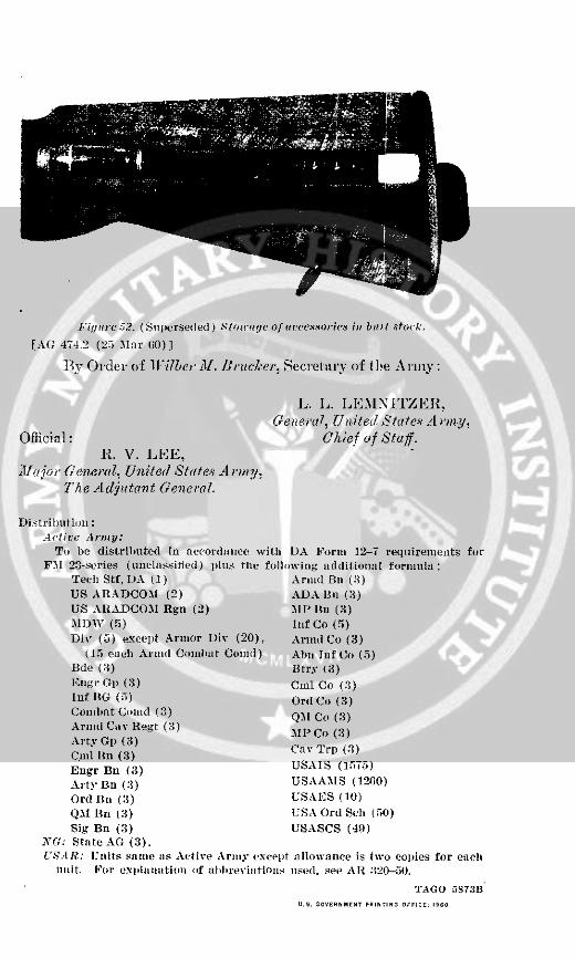
Figure 532. (Splllerse(led ) S tol-tge of Uac(escosic in bit I st:o(k.
[AG 474.2 (25 Mar 6(0)]
Ily Order of lilWber M. Bruckeer, Secretary of the Army:
L. L. LEMNITZER,General, Un ited States A rmy,
Official: Chief of Staff.R. V. LEE,
llajor General, Untited States Avrmy:The Adjultant General.
Distri bition:Active Army:
To be distributedl in accordance with DA Form 12-7 requirements forFM1 23-series (unclassified ) plus the following additional formula:
Tech Stf, DA (1) Armid Bn (3)US ARADCO.M (2) ADA IBn (3)US ALADCOM Rgn (2) MrP IBn (3)MIDW (5) Inf Co (5)Div (5) except Armor Div (20), Armd Co (3)
(15 each Al'md Combat Conil) Abn Inf Co (5)Bde (3) Btry (3)Engrl Gi) (3) Cml Co (3)Inf 13G (:5) Ord Co (3)Comnbat Clinld (3) QMl Co (3)Amid Cav Regt (3)
M P Co (3)Arty Gp) (3)~~~~~~~Cal fin (3)
Engr Bn (3) USAIS (15S5)Arty Bn (3) USAAMS (12o0)Ord Bu (3) USA.ES (10)QM rn (3) USA Ord Sch (50)Sig Bn (3) USASCS (49)
yG: State AG (3).'S:I R: UInits samne ls Active Army exceplt allowance is two copies for each
unit. For exilanaition of alilrevilitiolis used. see AL 3120-0().
TAGO 5873BU. GOvERNMENr PRINtln orcGS1, 19ON
FM 23-8C2
FIELD MANUAL
U.S. RIFLE, 7.62-MM, M14
FM 23-8 HEADQUARTERS,DEPARTMENT OF THE ARMY
CHANGES No. 2 WASHINGTON 25, D. C.,'15 Aitgust 1962
FM 23-8, 7 December 1959, is changed as follows:
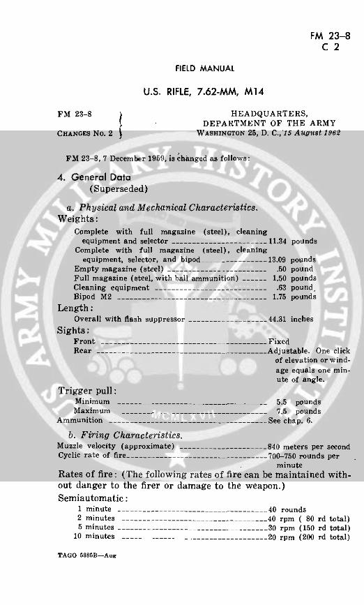
4. General Data(Superseded)
a. Physical and Mechanical Characteristics.Weights:
Complete with full magazine (steel), cleaningequipment and selector ________________._____11.34 pounds
Complete with full magazine (steel), cleaningequipment, selector, and bipod _-___.____13.09 pounds
Empty magazine (steel) _.---_.________.50 poundFull magazine (steel, with ball ammunition) .----- 1.50 poundsCleaning equipment .-. . ........____________ .63 pound,Bipod M2 ________.-._______________________ 1.75 pounds
Length:Overall with flash suppressor ................ 44.31 inches
Sights:Front ______________________________________ FixedRear .-.................................... Adjustable. One click
of elevation or wind-age equals one min-ute of angle.
Trigger pull:Minimum ______- _____________________ __ 5.5 poundsMaximum _______-_______________________ 7.5 pounds
Ammunition .-. . .._______.______________________ See chap. 6.
b. Firing Characteristics.Muzzle velocity (approximate) . .....___...__ 840 meters per secondCyclic rate of fire… ___.___- -_-_______________ 700-750 rounds per
minuteRates of fire: (The following rates of fire can be maintained with-out danger to the firer or damage to the weapon.)Semiautomatic:
1 minute _.___.______._______ 40 rounds2 minutes ___-- -------- ------ ___40 rpm ( 80 rd total)5 minutes …___________________________ 30 rpm (150 rd total)
10 minutes _________________ ________20 rpm (200 rd total)
TAGO 6385B--Aug

w 4 3 a"~~w-iu (.9(L xi- I- n
Lii~ aiaw ~~~~~~~~z hiw
o~~~ z 0 Z
u
"~ ~ ~~~ ~I (")
(5~ ~ ~ C. ' >-
I I - -J
W i J W i
_ Z Z)w i
N U)
0 0w -jC4 H
Z B .Q z r,
N '~ ~~~~~~~~~~~~~~~~I-
2C] ~ m
a 0
U) Z
Iii U 4-
~~~~~~~~~~~LI.
i~~~I --.
A 0 0 w
cr0~~~~~~
Er 0 c
" NoU)~~~~~~~~~~~~U
2 AO< 0z
2 ~~~~~~~~~~~~~~~~AGO 5385B
15 minutes .. ..................... 20 rpm (300 rd total)20 minutes .. .................. 20 rpm (400 rd total)30 or more minutes ___._______________ 15 rpm
Automatic:1 minute .. ............. 60 rounds2 minute -------------- .....50 rpm (100 rd total)5 minutes ------- ..........40 rpm (200 rd total)
10 minutes ____....---30 rpm (300 rd total)15 minutes _..___.._..________________30 rpm (450 rd total)20 minutes ---------------------------___…___ 25 rpm (500 rd total)30 minutes or more ______________________ _ 20 rpm
Range:Maximum effective (semiautomatic without bipod) 460 metersMaximum effective (semiautomatic with bipod) 700 meters*Maximum effective (automatic with bipod) .------ 460 meters**Maximum (M59 ball ammunition) .- 8-_____ 3725 meters
c. Definitions.Cyclic rate … ... The rate at which the weapon fires automatic-
ally.Maximum effective range .-.. The greatest distance at which a rifleman can
he expected to fire accurately to inflictcasualties or damage.
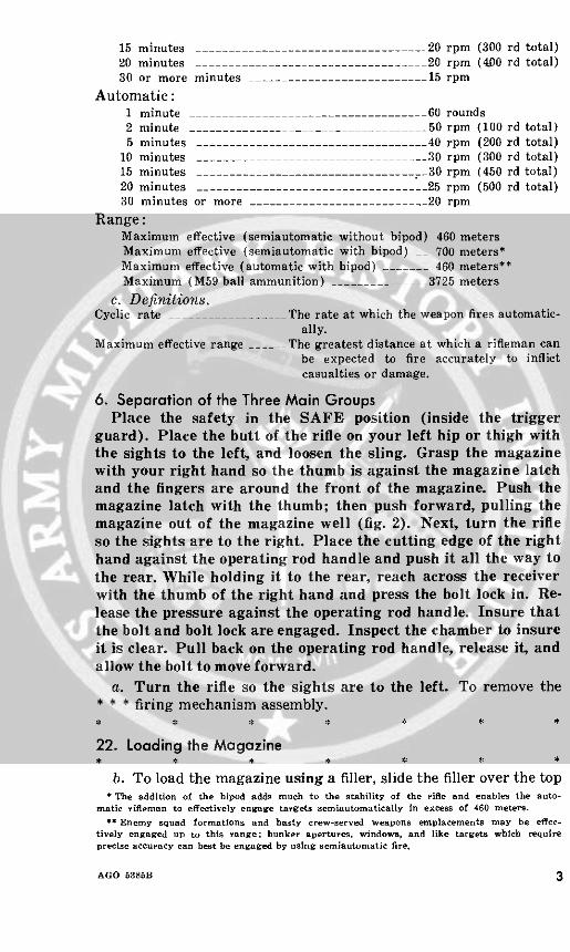
6. Separation of the Three Main GroupsPlace the safety in the SAFE position (inside the trigger
guard). Place the butt of the rifle on your left hip or thigh withthe sights to the left, and loosen the sling. Grasp the magazinewith your right hand so the thumb is against the magazine latchand the fingers are around the front of the magazine. Push themagazine latch with the thumb; then push forward, pulling themagazine out of the magazine well (fig. 2). Next, turn the rifleso the sights are to the right. Place the cutting edge of the righthand against the operating rod handle and push it all the way tothe rear. While holding it to the rear, reach across the receiverwith the thumb of the right hand and press the bolt lock in. Re-lease the pressure against the operating rod handle. Insure thatthe bolt and bolt lock are engaged. Inspect the chamber to insureit is clear. Pull back on the operating rod handle, release it, andallow the bolt to move forward.
a. Turn the rifle so the sights are to the left. To remove the** * firing mechanism assembly.
22. Loading the Magazine
b. To load the magazine using a filler, slide the filler over the top*The addition of the bipod adds much to the stability of the rifle and enables the auto-
matic riflema to effctively engage targets semiautomatically in excess of 460 meters.
** Enemy squad formations and hasty crew-served weapons emplacements may be effec-tively engaged up to this range; bunker apertures, windows, and like targets which requireprecise accuracy can best be engaged by using semiautomatic fire.
AGO 5385B 3
rear portion of the magazine (fig. 34.1). Insert a 5-round * * * themagazine filler.
Page 56.
Chart 2. Stoppages: Their Causes and Remedies
Stoppage Cause Remedy
Failure to feed … Defective or worn parts. Replace parts.
Failure to lock * * * * * *
Weak operating rod Replace spring.spring.
Failure to fire * * * * * *Failure to unlock _ __ * * *
Insufficient gas. Tighten gas cylinderplug.
Spindle valve closed. Open valve.
38. Description(Superseded)
The types of ammunition are easily identified by their individ-ual markings.
a. Ball. The M59 ball cartridge has a boattailed bullet (therear of the bullet is tapered). The bullet consists of a glidingmetal jacket, a steel core, and a lead antimony point and basefiller. The M80 ball cartridge bullet consists of a gliding metal orgilding metal clad steel jacket with a lead antimony slug. Ballammunition is unpainted.
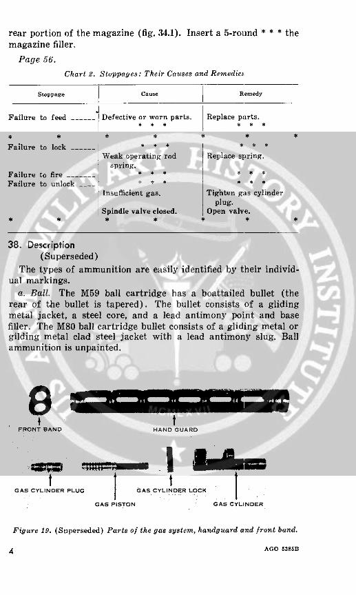
t tFRONT BAND HAND GUARD
' tGAS CYLINDER PLUG GAS CYLINDER LOCK
GAS PISTON GAS CYLINDER
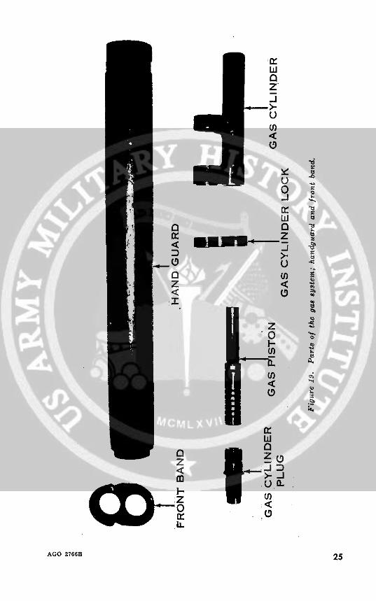
Figure 19. (Superseded) Parts of the gas system, handguard and front band.
4 AGO 5385B
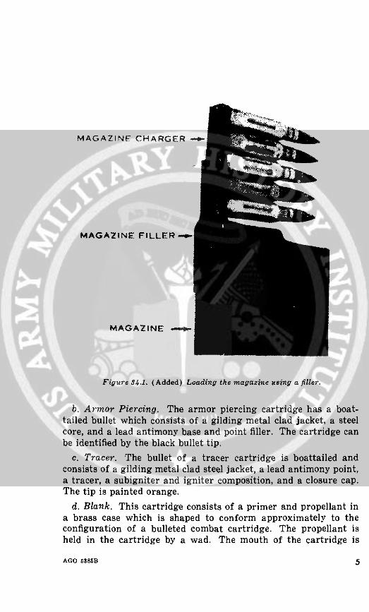
MAGAZINE CHARGER -
MAGAZINE FILLERsj
MAGAZINE -
Figure 34.1. (Added) Loading the magazine using a filler.
b. Armor Piercing. The armor piercing cartridge has a boat-tailed bullet which consists of a gilding metal clad jacket, a steelcore, and a lead antimony base and point filler. The cartridge canbe identified by the black bullet tip.
c. Tracer. The bullet of a tracer cartridge is boattailed andconsists of a gilding metal clad steel jacket, a lead antimony point,a tracer, a subigniter and igniter composition, and a closure cap.The tip is painted orange.
d. Blank. This cartridge consists of a primer and propellant ina brass case which is shaped to conform approximately to theconfiguration of a bulleted combat cartridge. The propellant isheld in the cartridge by a wad. The mouth of the cartridge is
AGO 5385B 5

sealed with a drop of red lacquer and then crimped to protectagainst air and moisture.
e. Dummy. The dummy cartridge case has six longitudinalcorrugations approximately one-third the length of the case.There are no markings on the bullet.
f. Cartridge, Grenade. The grenade cartridge has a five petalrose crimp on the mouth of the cartridge case and does not containa bullet. It is designed for use in the M14 rifle for projectinggrenades.
39. Ballistic DataSpecific data on 7.62-mm ammunition is contained in FT 7.62-
A-2, January 1962. The approximate maximum range and averagemuzzle velocity of ball ammunition are shown below.
Cartridg Max. range (meters) Average muzzle veZoeity(meters per second)
Ball M59 3725 839.7Ball M80 3549 839.7
6 AGO 6385B
APPENDIXREFERENCES
FM 23-5 US Rifle, Caliber .30, M1.FM 23-15 Browning Automatic Rifle, Caliber .30, M1918A2.FT 7.62-A-2 Gun, Machine, 7.62-MM, M60 on Mount, Machine
Gun, 7.62-MM, M122 and Rifle, 7.62-MM, M14.
BY ORDER OF THE SECRETARY OF THE ARMY:
G. H. DECKER,General, United States Army,
Official: Chief of Staff.J. C. LAMBERT,
Major General, United States Army,The Adjutant General.
Distribution:Active Army:
DCSPER (2) ARADCOM Rgn (2)ACSI (2) USCONARC (5)DCSLOG (2) LOGCOMD (2)DCSOPS (2) MDW (5)ACSRC (2) Armies (5)CRD (1) Corps (3)COA (1) Div (2) (CC (1))CINFO (1) Bde (1)TIG (1) Regt/Gp/bg (1)TJAG (1) Bn (5)TPMG (1) Co/Btry (5)Tech Stf, DA (1) except USATC (5)
CofOrd (5) Instl (1)ARADCOM (2)
NG: None.USAR: Same as active Army except allowance is one copy to each unit.For explanation of abbreviations used see AR 320-50.
u S. 2. GOVERNMENT PRINTING OFFICEi, *s2-650514
AGO 63856 7
FM 23-8
FIELD MANUAL HEADQUARTERS,DEPARTMENT OF THE ARMY
No. 23-8 WASHINGTON 25, D. C., 7 December 1959
U.S. RIFLE7.62-MM, M14
Paragraph Page
CHAPTER 1. INTRODUCTION
Purpose and scope ----.-----.----------------- 1 3Importance of mechanical training -________ 2 3Description of rifle .-......_______________ 3 3General data ….____._______________________ 4 5
2. MECHANICAL TRAININGSection I. DISASSEMBLY AND ASSEMBLY
General .-----________________---------- 5 7
Separation of the three main groups .- . . ...... 6 7Assembly of the three main groups_________ 7 9Disassembly of the barrel and receiver group_ 8 10Assembly of the barrel and receiver group_____ 9 15Disassembly of the bolt .-.... __________ 10 17Assembly of the bolt- .-.....___________ 11 19Disassembly of the rear sight . .------------- 12 22Assembly of the rear sight .-. ............. 13 23Disassembly of the gas system and handguard_ 14 24Assembly of the gas system and handguard___ 15 26Disassembly of the firing mechanism assembly_ 16 26Assembly of the firing mechanism assembly___ 17 28Disassembly of the magazine________________ -18 32Assembly of the magazine _________________- 19 32
II. CONVERSION FOR SEMIAUTOMATICAND AUTOMATIC FIRE.
Converting to fire selectively _______________ 20 34Converting to fire semiautomatically only - 21 35
CHAPTER 3. OPERATION AND FUNCTIONINGSection I. OPERATION
Loading the magazine- .-------------------- 22 40Loading the rifle ___-_________.._________. 23 40Top loading with 5-round magazine charger___ - 24 41Unloading and clearing the rifle .-___-______ 25 41Firing the rifle_ -- _------ ____________ 26 41
AGO 2766B 1
Paragraph PageSection II. FUNCTIONING
Semiautomatic ______.-- -------------------- 27 43Automatic ____________.-------------------- 28 54
CHAPTER 4. STOPPAGES AND IMMEDIATE ACTIONStoppage_ -_-_____ ____--____ -______---- 29 56Immediate action- .-.........____._______. 30 56
5. MAINTENANCEGeneral ______________.---------------- - 31 59Cleaning materials, lubricants, and equipment 32 59Cleaning the rifle -------------------------- 33 62Normal maintenance --.---------------------- 34 68
Special maintenance …_________8_______.___ 35 68Storage ……______________……8_.___--- ----- 36 70
CHAPTER 6. AMMUNITIONGeneral -_______________________________ 37 71
Description ____________________________…__. 38 71Ballistic data ........................... 39 71Packaging_ ___________..-..........____ 40 72Care, handling, and preservation -.- . ........ 41 72Storage …___________________________________ 42 73
APPENDIX. REFERENCES -. ____ 74
AGO 2766B
CHAPTER 1INTRODUCTION
1. Purpose and Scopea. This manual is a guide for commanders and instructors in
presenting instruction and training in the mechanical operationof the M14 rifle. It includes a detailed description of the rifleand its general characteristics; procedures for detailed disassem-bly and assembly; an explanation of functioning; a discussion ofthe types of stoppages and the immediate action applied to reducethem; a description of the ammunition used; and instructions onthe care, cleaning, and handling of both the weapon andammunition.
b. Marksmanship training is covered i 23-5 an 23-
2. Importance of Mechanical Training
The rifle is the infantryman's basic weapon. It gives him anindividual and powerful capability for combat. To get the mostout of his individual combat capability, the infantryman mustdevelop two skills to an equal degree-he must be able to fire hisweapon well enough to get hits on battlefield targets and he mustknow enough about its working parts to keep them operatingsmoothly so the rifle will never fail him. The infantryman getshis firing skill on known distance and TRAINFIRE ranges andhe learns how to keep his rifle working from the mechanicaltraining that is detailed in this manual.
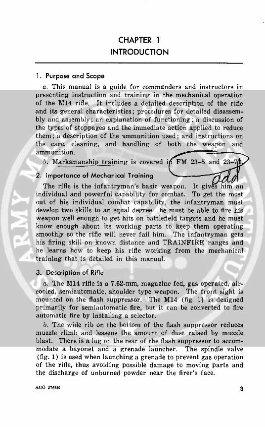
3. Description of Riflea. The M14 rifle is a 7.62-mm, magazine fed, gas operated, air-
cooled, semiautomatic, shoulder type weapon. The front sight ismounted on the flash suppressor. The M14 (fig. 1) is designedprimarily for semiautomatic fire, but it can be converted to fireautomatic fire by installing a selector.
b. The wide rib on the bottom of the flash suppressor reducesmuzzle climb and lessens the amount of dust raised by muzzleblast. There is a lug on the rear of the flash suppressor to accom-modate a bayonet and a grenade launcher. The spindle valve(fig. 1) is used when launching a grenade to prevent gas operationof the rifle, thus avoiding possible damage to moving parts andthe discharge of unburned powder near the firer's face.
AGO 2766B 3

x -:s~~~~2
cr iii: :: S: 9. :
Iii 0 ~ ~~~~~O : .. t.: L:..
d r:~ t Uk~
*11 SuS ~ ~ ~ : ;S0 't 00 ~ ~ ~~~ r , .X X0;, . Sf.-
0 ~ ~~~~~~~ a :0A~~~~ I ::X:0~~~~~~~~~~~~~~G 76
c. The sear release, selector shaft, and connector assembly,mounted on the right side of the receiver and positioned by theselector shaft lock, do not operate during semiautomatic firing.
d. The web sling is used for firing on the distance range and forcarrying the weapon. Each rifleman adjusts his sling accord-ing to individual need.
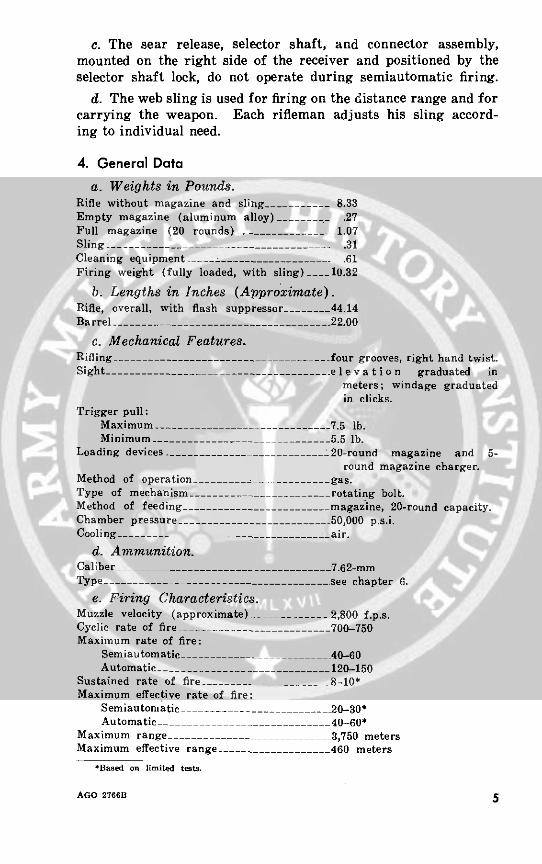
4. General Dataa. Weights in Pounds.
Rifle without magazine and sling __- ______ 8.33Empty magazine (aluminum alloy) ________ .27Full magazine (20 rounds) . . ............ 1.07Sling . .. .....---_______ ____________- .31Cleaning equipment ___- ....__________. .61Firing weight (fully loaded, with sling) ___10.32
b. Lengths in Inches (Approximate).Rifle, overall, with flash suppressor ..... 44.14Barrel _________.__-------_______.- 22.00
c. Mechanical Features.Rifling - --.... _..-------------- _ four grooves, right hand twist.Sight ---------- ______-____________._ e I e v a t i o n graduated in
meters; windage graduatedin clicks.
Trigger pull:Maximum -- ___ -___ __________7.5 lb.Minimum - -____________ -________5.5 lb.
Loading devices - -_________________ ___20-round magazine and 5-round magazine charger.
Method of operation … . ........... gas.Type of mechanism . ..-...___.___.__ rotating bolt.Method of feeding --_______________________magazine, 20-round capacity.Chamber pressure -- -- ---_____________._- 50,000 p.s.i.Cooling_ _ …______-___.____ _ air.
d. Ammunition.Caliber__ ---------------- _______7.62-mmType _.s_________________________ See chapter 6.
e. Firing Characteristics.Muzzle velocity (approximate) - -__ ________2,800 f.p.s.Cyclic rate of fire ------------ . ..........700-750Maximum rate of fire:
Semiautomatic _ 40-60Automatic ……_________________________=.120-150
Sustained rate of fire .. ______ 8-10'Maximum effective rate of fire:
Semiautomatic . ..---____ .__ 20-30*Automatic _ _ 40-60*
Maximum range 3,750 metersMaximum effective range . . ..._-_--------- 460 meters
Based on limited tests.
AGO 2766B 5

f. Definitions.Cyclic rate .............._______________. the rate at which the weapon
fires automatically.Maximum rate of fire ____________________-the fastest rate at which a
well-trained rifleman canfire.
Sustained rate of fire ____________________. the rate at which a weaponcan fire indefinitely withoutseriously overheating.
Maximum effective rate of fire -------------- the maximum number ofrounds the average riflemancan fire and still get a rea-sonable number of hits onthe target.
Maximum range- .-...........___________. the greatest distance theweapon can fire.
Maximum effective range __________________the greatest distance at whicha rifleman can be expectedto fire accurately to inflictcasualties or damage.
6 AGO 2766B
CHAPTER 2
MECHANICAL TRAINING
Section I. DISASSEMBLY AND ASSEMBLY
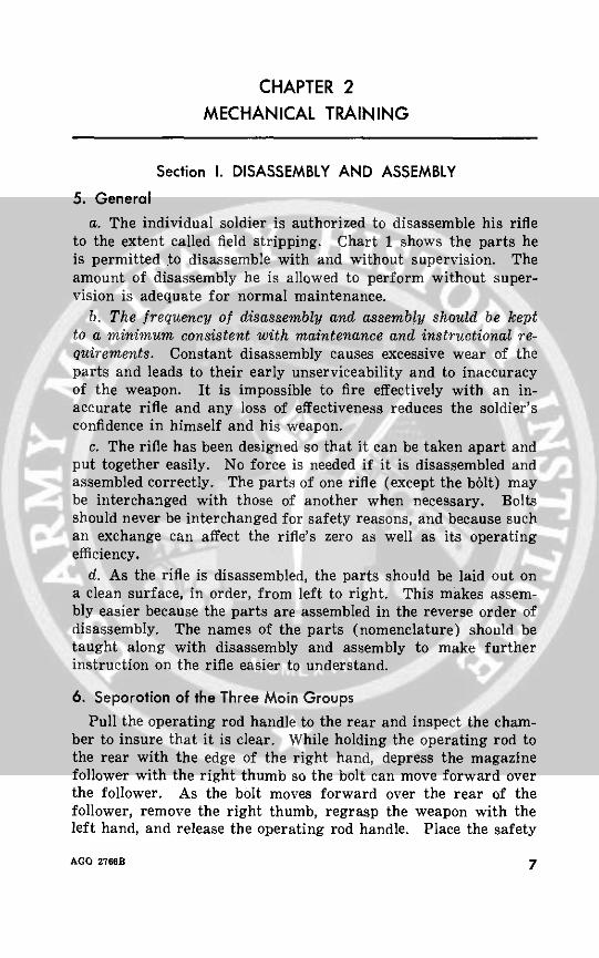
5. Generala. The individual soldier is authorized to disassemble his rifle
to the extent called field stripping. Chart 1 shows the parts heis permitted to disassemble with and without supervision. Theamount of disassembly he is allowed to perform without super-vision is adequate for normal maintenance.
b. The frequency of disassembly and assembly should be keptto a minimum consistent with maintenance and instructional re-quirements. Constant disassembly causes excessive wear of theparts and leads to their early unserviceability and to inaccuracyof the weapon. It is impossible to fire effectively with an in-accurate rifle and any loss of effectiveness reduces the soldier'sconfidence in himself and his weapon.
c. The rifle has been designed so that it can be taken apart andput together easily. No force is needed if it is disassembled andassembled correctly. The parts of one rifle (except the bolt) maybe interchanged with those of another when necessary. Boltsshould never be interchanged for safety reasons, and because suchan exchange can affect the rifle's zero as well as its operatingefficiency.
d. As the rifle is disassembled, the parts should be laid out ona clean surface, in order, from left to right. This makes assem-bly easier because the parts are assembled in the reverse order ofdisassembly. The names of the parts (nomenclature) should betaught along with disassembly and assembly to make furtherinstruction on the rifle easier to understand.
6. Separation of the Three Main GroupsPull the operating rod handle to the rear and inspect the cham-
ber to insure that it is clear. While holding the operating rod tothe rear with the edge of the right hand, depress the magazinefollower with the right thumb so the bolt can move forward overthe follower. As the bolt moves forward over the rear of thefollower, remove the right thumb, regrasp the weapon with theleft hand, and release the operating rod handle. Place the safety
AGO 2766B 7
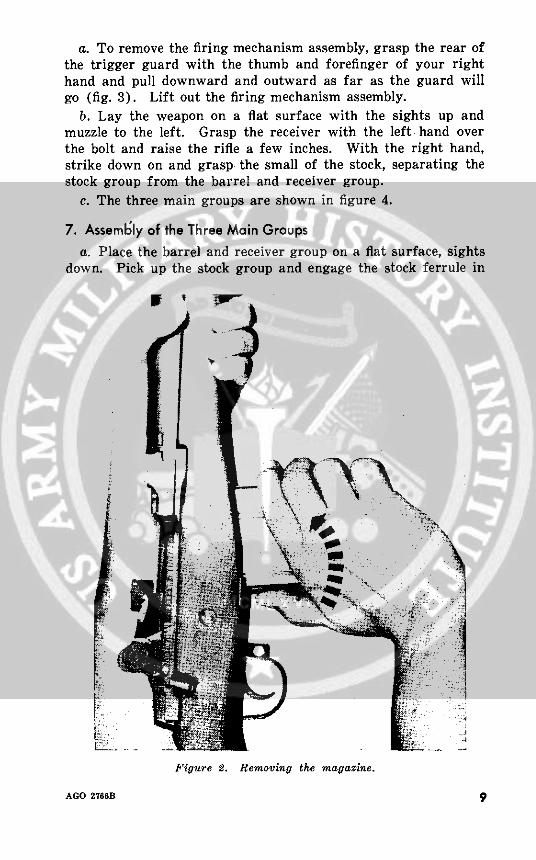
in the safe position. Next, place the butt of the rifle on yourleft hip or thigh with the sights to the left and loosen the sling.Grasp the magazine with your right hand so that the thumb isagainst the magazine latch and the fingers are around the frontof the magazine. Push the magazine latch with the thumb, thenpull the magazine out of the receiver (fig. 2).
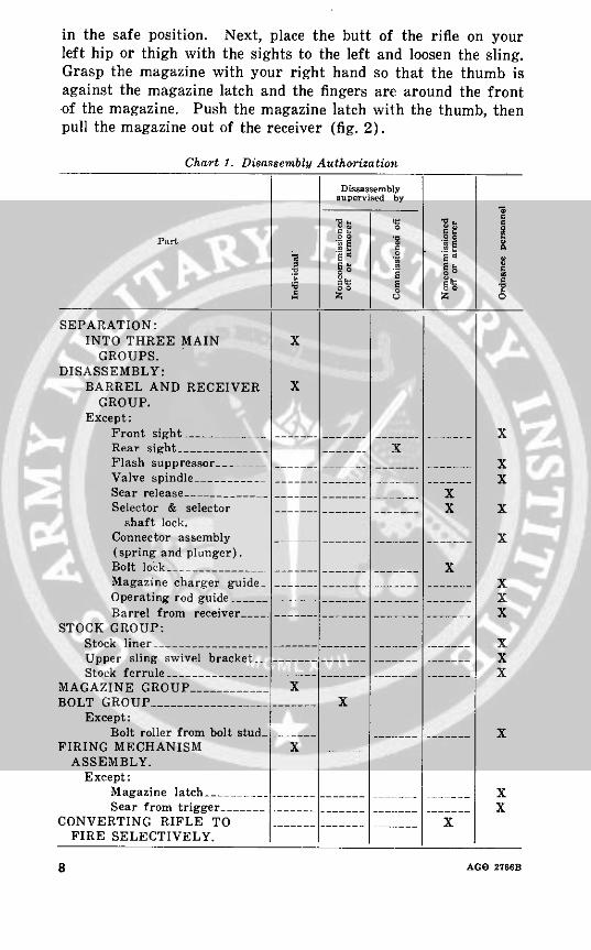
Chart 1. Disassembly Authorization
Dissassemblysupervised by
Part .0 E|
S E·" ~Ecc E C$ ·i
SEPARATION:INTO THREE MAIN X
GROUPS.DISASSEMBLY:
BARREL AND RECEIVER XGROUP.
Except:Front sight.____ _-__ ______. ______ _____ XRear sight .-..__ _ _____ XFlash suppressor . .... ............. I XValve spindle -_______ - __-___.- -___ - -______ XSear release -________= ___-___._____ - - XSelector & selector ______.______ _I X X
shaft lock.Connector assembly …_… __- __ _________ X(spring and plunger).Bolt lock __________ .______.______ ______ XMagazine charger guide -........ ___..---__------.. .i XOperating rod guide_____ --.- _ ____-- __-___ ____ XBarrel from receiver… ---............................ X
STOCK GROUP:Stock liner ________.. ..___ _____.__-------- .. __ __._-I XUpper sling swivel bracket __ -- --.-- __ ______---- I XStock ferrule ------------- -------------- .-- ---- --..... I X
MAGAZINE GROUP -__________ XBOLT GROUP - --_______________- .___ X
Except:Bolt roller from bolt stud -... . ...........I X
FIRING MECHANISM X __ _ASSEMBLY.
Except:Magazine latch _ -__-________- ____-- ___ -__ ___ XSear from trigger __......................... X
CONVERTING RIFLE TO --______ ______ -____ XFIRE SELECTIVELY.
8 AGO 2766B
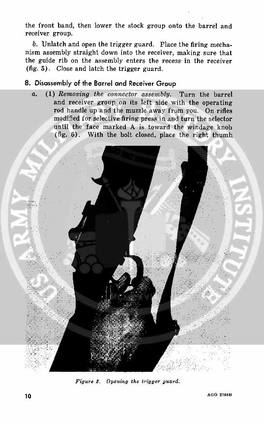
a. To remove the firing mechanism assembly, grasp the rear ofthe trigger guard with the thumb and forefinger of your righthand and pull downward and outward as far as the guard willgo (fig. 3). Lift out the firing mechanism assembly.
b. Lay the weapon on a flat surface with the sights up andmuzzle to the left. Grasp the receiver with the left hand overthe bolt and raise the rifle a few inches. With the right hand,strike down on and grasp the small of the stock, separating thestock group from the barrel and receiver group.
c. The three main groups are shown in figure 4.
7. Assembly of the Three Main Groupsa. Place the barrel and receiver group on a flat surface, sights
down. Pick up the stock group and engage the stock ferrule in
I I
Figure 2. Removing the magazine.
AGO 2766B 9
the front band, then lower the stock group onto the barrel andreceiver group.
b. Unlatch and open the trigger guard. Place the firing mecha-nism assembly straight down into the receiver, making sure thatthe guide rib on the assembly enters the recess' in the receiver(fig. 5). Close and latch the trigger guard.
8. Disassembly of the Barrel and Receiver Groupa. (1) Removing the connector assembly. Turn the barrel
and receiver group on its left side with the operatingrod handle up and the muzzle away from you. On riflesmodified for selective firing press in and turn the selectoruntil the face marked A is toward the windage knob(fig. 6). With the bolt closed, place the right thumb.
Figure 3. Opening the trigger guard.
10 AGO 2766B10 AGO 27 61

-32
w ~ ~
I'
U)
(I Iz
oo
D 0
w
2~~~~~~~
oo N 00~~~~
r a\fzJ
u
AGO 2766B
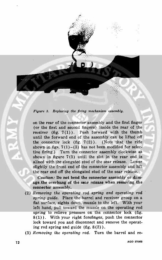
Figure 5. Replacing the firing mechanism assembly.
on the rear of the connector assembly and the first finger(or the first and second fingers) inside the rear of thereceiver (fig. 7(1)). Push forward with the thumbuntil the forward end of the assembly can be lifted offthe connector lock (fig. 7(2)). (Note that the rifleshown in figs. 7(1)-(3) has not been modified for selec-tive firing.) Turn the connector assembly clockwise asshown in figure 7(3) until the slot in the rear end isalined with the elongated stud of the sear release. Lowerslightly the front end of the connector assembly and liftthe rear end off the elongated stud of the sear release.
Caution: Do not bend the connector assembly or dam-age.the overhang of the sear release when removing theconnector assembly.
(2) Removing the operating rod spring and operating rodspring guide. Place the barrel and receiver group on aflat surface, sights down, muzzle to the left. With yourleft hand, pull toward the muzzle on the operating rodspring to relieve pressure on the connector lock (fig.8(1)). With your right forefinger, push the connectorlock toward you and disconnect and remove the operat-ing rod spring and guide (fig. 8(2)).
(3) Removing the operating rod. Turn the barrel and re-
12 AGO 2766B
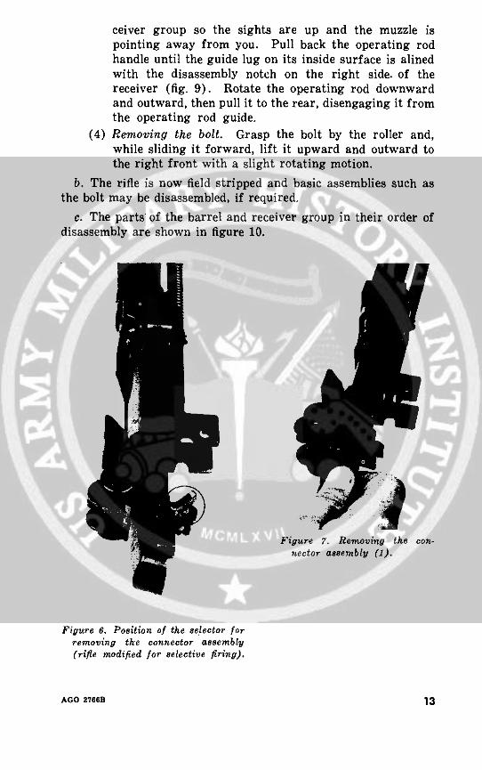
ceiver group so the sights are up and the muzzle ispointing away from you. Pull back the operating rodhandle until the guide lug on its inside surface is alinedwith the disassembly notch on the right side. of thereceiver (fig. 9). Rotate the operating rod downwardand outward, then pull it to the rear, disengaging it fromthe operating rod guide.
(4) Removing the bolt. Grasp the bolt by the roller and,while sliding it forward, lift it upward and outward tothe right front with a slight rotating motion.
b. The rifle is now field stripped and basic assemblies such asthe bolt may be disassembled, if required.
c. The parts of the barrel and receiver group in their order ofdisassembly are shown in figure 10.
Figure 7. Removing the con-nector assembly (1).
Figure 6. Position of the selector forremoving the connector assembly(rifle modified for selective firing).
AGO 2766B 13

Figure 7-Continued. (2)
Figure 7-Continued. (3)
14 AGO 276'B
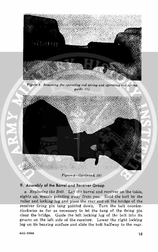
Figure 8. Removing the operating rod spring and operating rod springguide. (1)
Figure 8-Continued. (2)
9. Assembly of the Barrel and Receiver Group
a. Replacing the Bolt. Lay the barrel and receiver on the table,sights up, muzzle pointing away from you. Hold the bolt by theroller and locking lug and place the rear end on the bridge of thereceiver firing pin tang pointed down. Turn the bolt counter-clockwise as far as necessary to let the tang of the firing pinclear the bridge. Guide the left locking lug of the bolt into itsgroove on the left side of the receiver. Lower the right lockinglug on its bearing surface and slide the bolt halfway to the rear.
AGO 2766f 15
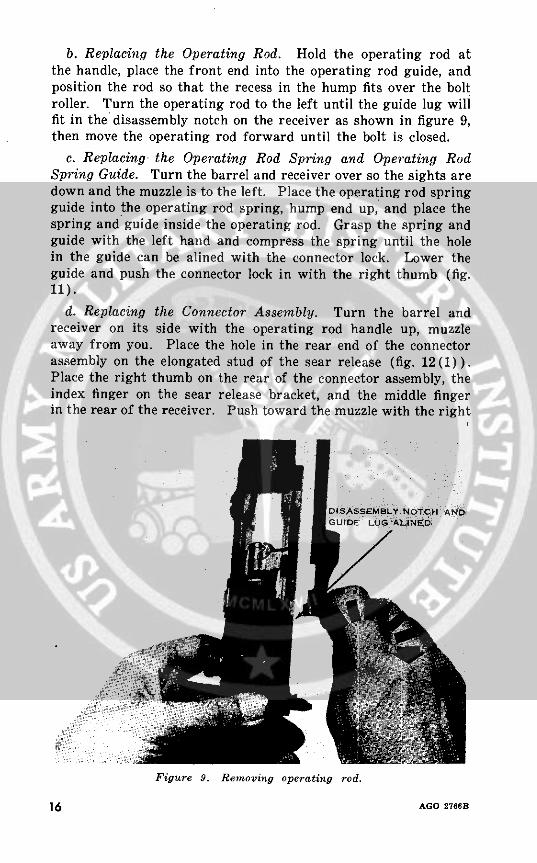
b. Replacing the Operating Rod. Hold the operating rod atthe handle, place the front end into the operating rod guide, andposition the rod so that the recess in the hump fits over the boltroller. Turn the operating rod to the left until the guide lug willfit in the disassembly notch on the receiver as shown in figure 9,then move the operating rod forward until the bolt is closed.
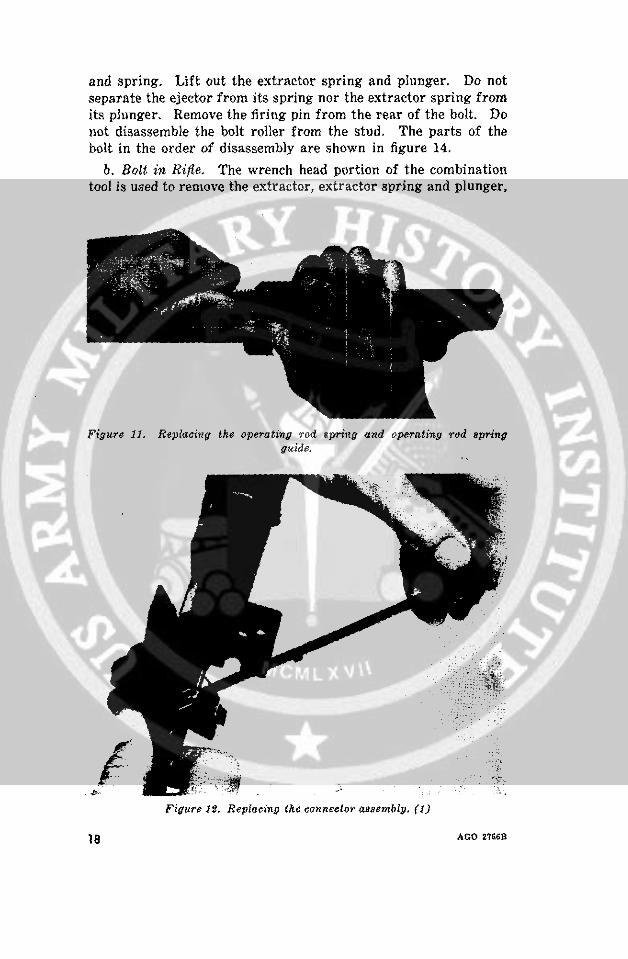
c. Replacing the Operating Rod Spring and Operating RodSpring Guide. Turn the barrel and receiver over so the sights aredown and the muzzle is to the left. Place the operating rod springguide into the operating rod spring, hump end up, and place thespring and guide inside the operating rod. Grasp the spring andguide with the left hand and compress the spring until the holein the guide can be alined with the connector lock. Lower theguide and push the connector lock in with the right thumb (fig.11).
d. Replacing the Connector Assembly. Turn the barrel andreceiver on its side with the operating rod handle up, muzzleaway from you. Place the hole in the rear end of the connectorassembly on the elongated stud of the sear release (fig. 12(1)).Place the right thumb on the rear of the connector assembly, theindex finger on the sear release bracket, and the middle fingerin the rear of the receiver. Push toward the muzzle with the right
DISASSEMBLy NOTCH ANDGUIDE: LUGLNED
Figure 9. Removing operating rod.
16 AGO 2766B
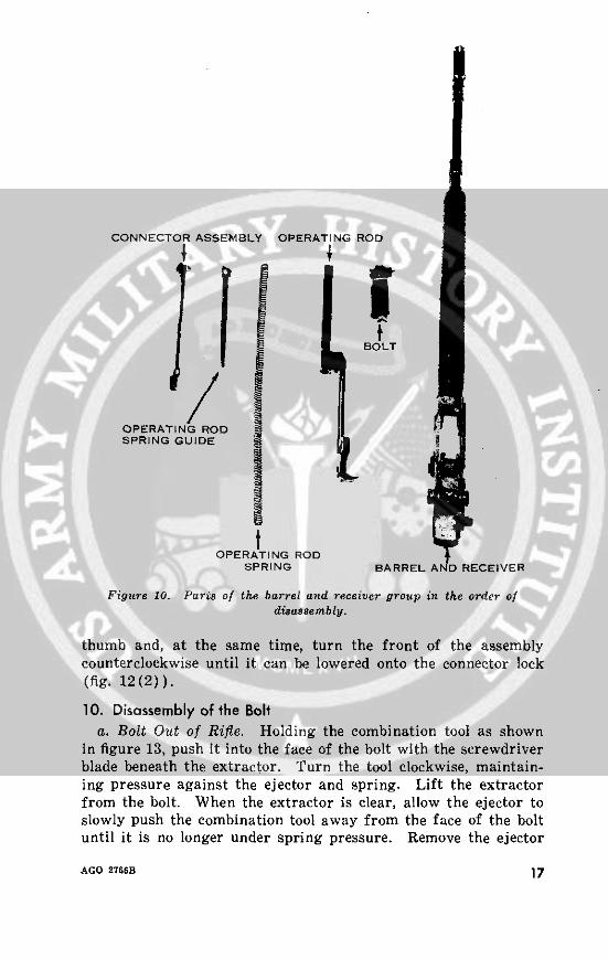
CONNECTOR ASSEMBLY OPERATING ROD
BOLT
OPERATING RODSPRING GUIDE
OPERATING RODSPRING BARREL AND RECEIVER
Figure 10. Paris of the barrel and receiver group in the order ofdisassembly.
thumb and, at the same time, turn the front of the assemblycounterclockwise until it can be lowered onto the connector lock(fig. 12(2)).
10. Disassembly of the Bolta. Bolt Out of Rifle. Holding the combination tool as shown
in figure 13, push it into the face of the bolt with the screwdriverblade beneath the extractor. Turn the tool clockwise, maintain-ing pressure against the ejector and spring. Lift the extractorfrom the bolt. When the extractor is clear, allow the ejector toslowly push the combination tool away from the face of the boltuntil it is no longer under spring pressure. Remove the ejector
AGO 2766B 17
and spring. Lift out the extractor spring and plunger. Do notseparate the ejector from its spring nor the extractor spring fromits plunger. Remove the firing pin from the rear of the bolt. Donot disassemble the bolt roller from the stud. The parts of thebolt in the order of disassembly are shown in figure 14.
b. Bolt in Rifle. The wrench head portion of the combinationtool is used to remove the extractor, extractor spring and plunger,
Figure 11. Replacinfg the operating rod spring and operating rod springguide.
Figure 12. Replacing the connector aassembly. (I)
a18 AGO 2U66
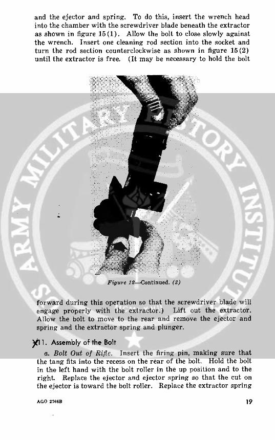
and the ejector and spring. To do this, insert the wrench headinto the chamber with the screwdriver blade beneath the extractoras shown in figure 15(1). Allow the bolt to close slowly againstthe wrench. Insert one cleaning rod section into the socket andturn the rod section counterclockwise as shown in figure 15(2)until the extractor is free. (It may be necessary to hold the bolt
Figure 12--Continued. (2)
forward during this operation so that the screwdriver blade willengage properly with the extractor.) Lift out the extractor.Allow the bolt to move to the rear and remove the ejector andspring and the extractor spring and plunger.
)1 . Assembly of the Bolta. Bolt Out of Rifle. Insert the firing pin, making sure that
the tang fits into the recess on the rear of the bolt. Hold the boltin the left hand with the bolt roller in the up position and to theright. Replace the ejector and ejector spring so that the cut onthe ejector is toward the bolt roller. Replace the extractor spring
AGO 2766B 19
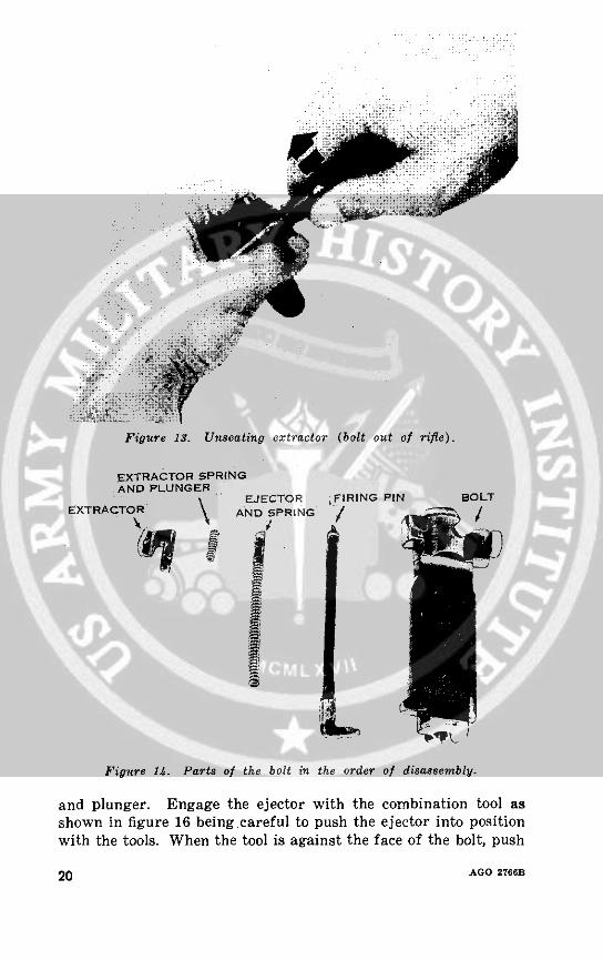
Figure 13. Unseating extractor (bolt out of rifle).
EXTRACTOR SPRINGAND PLUNGER
EJECTOR jFIRING PIN BOLTEXTRACTOR AND SPRING
Figure 14. Parts of the bolt in the order of disassembly.
and plunger. Engage the ejector with the combination tool asshown in figure 16 beingcareful to push the ejector into positionwith the tools. When the tool is against the face of the bolt, push
20 AGO 2766B
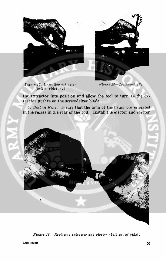
Figure 15. Unseating extractor Figure 15-Continued. (2)(bolt in rifle). (1)
the extractor into position and allow the tool to turn as the ex-tractor pushes on the screwdriver blade.
b. Bolt in Rifle. Insure that the tang of the firing pin is seatedin the recess in the rear of the bolt. Install the ejector and ejector
Figure 16. Replacing extractor and ejector (bolt out of rifle).
AGO 2766B 21
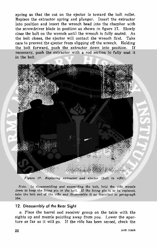
spring so that the cut on the ejector is toward the bolt roller.Replace the extractor spring and plunger. Insert the extractorinto position and insert the wrench head into the chamber withthe screwdriver blade in position as shown in figure 17. Slowlyclose the bolt on the wrench until the wrench is fully seated. Asthe bolt closes, the ejector will contact the wrench first. Takecare to prevent the ejector from slipping off the wrench. Holdingthe bolt forward, push the extractor down into position. Ifnecessary, push the extractor with a rod section to fully seat itin the bolt.
Figure 17. Replacing extractor and ejector (bolt in rifle).
Note. In disassembling and assembling the bolt, hold the rifle muzzledown to keep the firing pin in the bolt. If the firing pin is to he replaced,take the bolt out of the rifle and disassemble it as described in paragraph10a.
12. Disassembly of the Rear Sighta. Place the barrel and receiver group on the table with the
sights up and muzzle pointing away from you. Lower the aper-ture as far as it will go. If the rifle has been zeroed, check the
22 AGOD 2766B
reading on the elevating knob and write it down. You will needthis reading when you replace the elevating knob.
b. Unscrew the nut in the center of the windage knob with thescrewdriver blade of the combination tool. (Be careful not todamage the slot in the nut.) The nut will become loosened butit cannot be removed. Unscrew the windage knob counterclock-wise until the windage knob assembly can be removed. Pushforward lightly on the right side of the rear sight base andremove the rear sight elevating pinion assembly by withdrawingit to the left. Pull the aperture up about one-half inch and placeyour right thumb underneath it, then push forward and upward,removing the aperture, cover, and base.
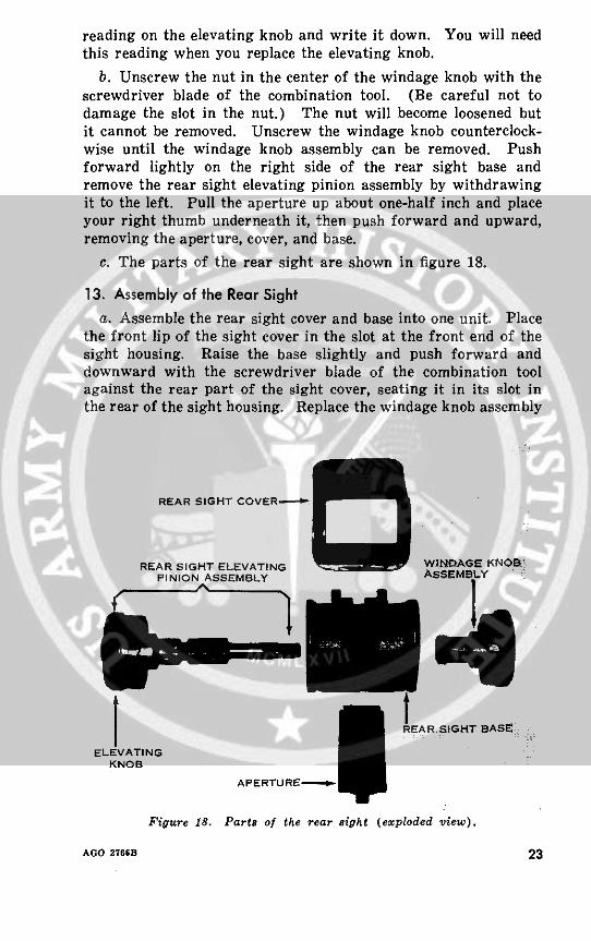
c. The parts of the rear sight are shown in figure 18.
13. Assembly of the Rear Sighta. Assemble the rear sight cover and base into one unit. Place
the front lip of the sight cover in the slot at the front end of thesight housing. Raise the base slightly and push forward anddownward with the screwdriver blade of the combination toolagainst the rear part of the sight cover, seating it in its slot inthe rear of the sight housing. Replace the windage knob assembly
REAR SIGHT COVER- O
REAR SIGHT ELEVATING WINDAGE KNOBPINION ASSEMBLY ASSEMBLY
5 REAR SIGHT BASEM
ELEVATINGKNOB
APERTURE I
Figure 18. Parts of the rear sight (exploded view).
AGO 276GB 23
and screw it in until it draws the base to the center position onthe windage gage. Push forward, lightly, on the right rear ofthe base while inserting the elevating pinion assembly from theleft, meshing the pinion with the teeth on the aperture until thethreaded end of the pinion contacts the windage knob. Tightenthe nut in the center of the windage knob until you feel a stiffen-ing resistance. When it is tight, back it off one complete turn.This should give the correct tension. Make sure that the readingthat was on the elevating knob before disassembly is opposite theindex mark on the receiver when the aperture is at its lowestposition. Then tighten the elevating knob screw.
b. Obtaining the proper tension is extremely important; with-out it, the sight will not hold its adjustment in elevatidn. If youcannot hear clear, sharp clicks when you turn the elevating knob,or if the aperture drops when the rifle is fired, check the tensionas follows:
(1) Run the aperture up about 20 clicks.(2) Press down on top of the aperture with the thumb.(3) If the aperture drops, the tension must be adjusted.
c. To adjust the tension, first make sure that the elevatingknob screw is tight. Next, tighten the windage knob nut oneclick at a time. Test the tension as described in (1) and (2)above after each click and continue the process until the aperturedoes not drop. If the proper tension cannot be set by doing this,the sight must be repaired or replaced.
d. When sight tension is properly applied, the windage knobmay be hard to turn. This may be overcome by pressing inwardon the elevating pinion assembly with the left thumb while turn-ing the windage knob with the right hand,
14. Disassembly of the Gas System and Handguarda. Using the wrench of the combination tool, loosen and remove
the gas cylinder plug. Tilt the muzzle down and remove the gaspiston from the gas cylinder. Unscrew the gas cylinder lock andslide the lock and cylinder forward so that the gas port is exposed.Slip the front band forward toward the front sight. Push thehandguard toward the front sight and lift it from the barrel.
Note. The sharp edges of the grooves and other surfaces on the pistonhelp to permit proper functioning of the gas system. Do not dull thesesharp edges. Also, NEVER use any abrasive material to clean any com-ponents of the gas system. Tolerances are close and must not be altered.Remember, a clean system is not necessarily a shiny one.
b. The parts of the gas system, and the handguard and frontband are shown in figure 19.
24 AGO 2766?
Li
0
Z'
O c~0
5 3
-° 2-I
itz C
Ia a
U)
AGO 2766 >B
a.z vU
AGO 2766B 25
15. Assembly of the Gas System and HandguardPlace the rifle on a flat surface, sights up and muzzle to the
right. Engage the ends of the band on the handguard with thefront (muzzle) end of the slots that are on the rear of the barreland slide the handguard rearward. (Do not snap the handguardinto its installed position.) Replace the front band. Slide thegas cylinder rearward through the front band. Tighten the gascylinder lock by hand to its fully assembled position, then back itoff until the loop is alined with the gas cylinder. Replace the gaspiston, the flat part toward the barrel and the open end towardthe muzzle. Replace the gas cylinder plug and tighten it securelywith the wrench of the combination tool.
Note. Before tightening the gas cylinder plug, be certain that the pistonmoves freely and protrudes through the cylinder. Then, tighten the gascylinder plug, making certain it is secure.
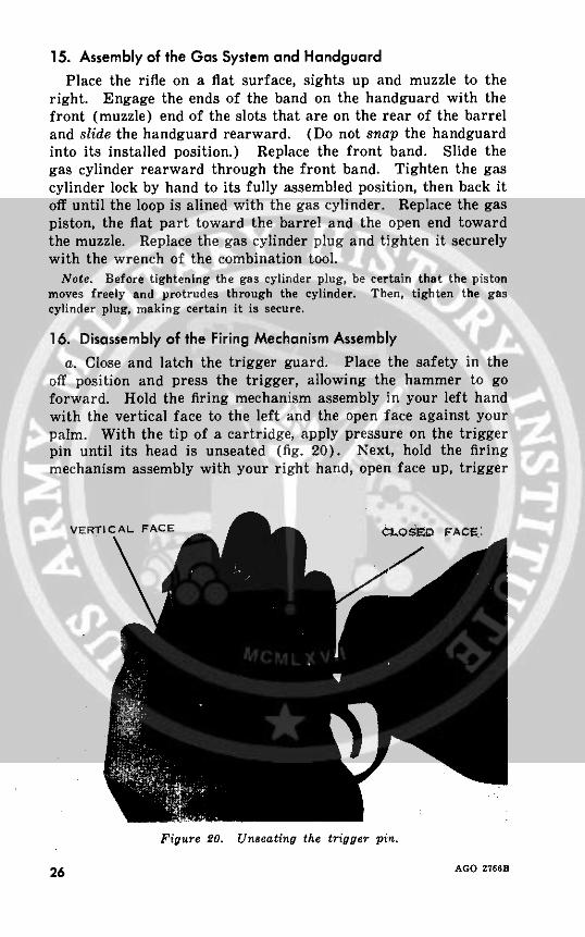
16. Disassembly of the Firing Mechanism Assemblya. Close and latch the trigger guard. Place the safety in the
off position and press the trigger, allowing the hammer to goforward. Hold the firing mechanism assembly in your left handwith the vertical face to the left and the open face against yourpalm. With the tip of a cartridge, apply pressure on the triggerpin until its head is unseated (fig. 20). Next, hold the firingmechanism assembly with your right hand, open face up, trigger
VERTICAL FACEF
Figure 20. Unseating the trigger pin.
26 AGO 2766B

guard to the left, forefinger over the sear, thumb on the verticalface, and apply a pinching pressure with the thumb and indexfinger as shown in figure 21 and remove the trigger pin. Slowlyrelease the pressure, allowing the hammer spring to expand.
b. Transfer the firing mechanism assembly to your left handwith the vertical face still toward your body and the open face up.With your right hand, remove the trigger and sear assembly,hammer spring housing, hammer spring, and hammer springplunger.
c. Unlatch and open the trigger guard. Hold the firing mecha-nism assembly in your left hand with the vertical face away from
Figure 1. Removing the trigger pin.
AGO 2766B 27

your body and the open face down. Push out the hammer pinwith the tip of a cartridge (fig. 22). Turn the trigger housingover; move the hammer slightly to the rear and lift it oht.
d. Leave the trigger guard unlatched. Turn the trigger hous-ing over so the open face is down and push the stud of the safetyfrom its hole with the tip of a cartridge. Remove the safety andsafety spring by lifting them out of the trigger housing.
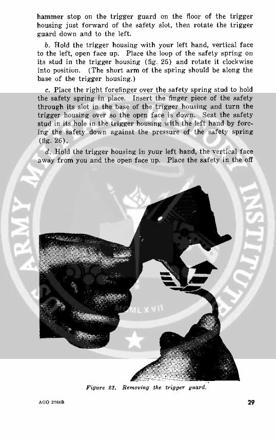
e. Hold the rear of the trigger housing with the left hand asshown in figure 23. Grasp the trigger guard with your right handand slide it to the rear until the hammer pin holes in the wingsof the trigger guard are just forward of the safety stud hole.Cant the guard to the right, push it forward and up, and removeit from the trigger housing.
f. The magazine latch should not be removed from the triggerhousing.
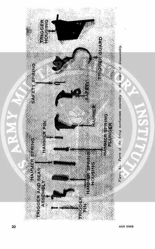
g. The parts of the firing mechanism assembly in the order ofdisassembly are shown in figure 24.
17. Assembly of the Firing Mechanism Assemblya. Hold the rear of the trigger housing with your left hand,
the vertical face away from you, open face to the right. Place the
Figure 22. Removing the hammer pin.
28 AGO 2766B
hammer stop on the trigger guard on the floor of the triggerhousing just forward of the safety slot, then rotate the triggerguard down and to the left.
b. Hold the trigger housing with your left hand, vertical faceto the left, open face up. Place the loop of the safety spring onits stud in the trigger housing (fig. 25) and rotate it clockwiseinto position. (The short arm of the spring should be along thebase of the trigger housing.)
c. Place the right forefinger over the safety spring stud to holdthe safety spring in place. Insert the finger piece of the safetythrough its slot in the base of the trigger housing and turn thetrigger housing over so the open face is down. Seat the safetystud in its hole in the trigger housing with the left hand by forc-ing the safety down against the pressure of the safety spring(fig. 26).
d. Hold the trigger housing in your left hand, the vertical faceaway from you and the open face up. Place the safety in the off
Figure 23. Removing the trigger guard.
AGO 2766B 29
~i~i~!~~ :~:~ ~ ::
n X30
30 AGO 2766B
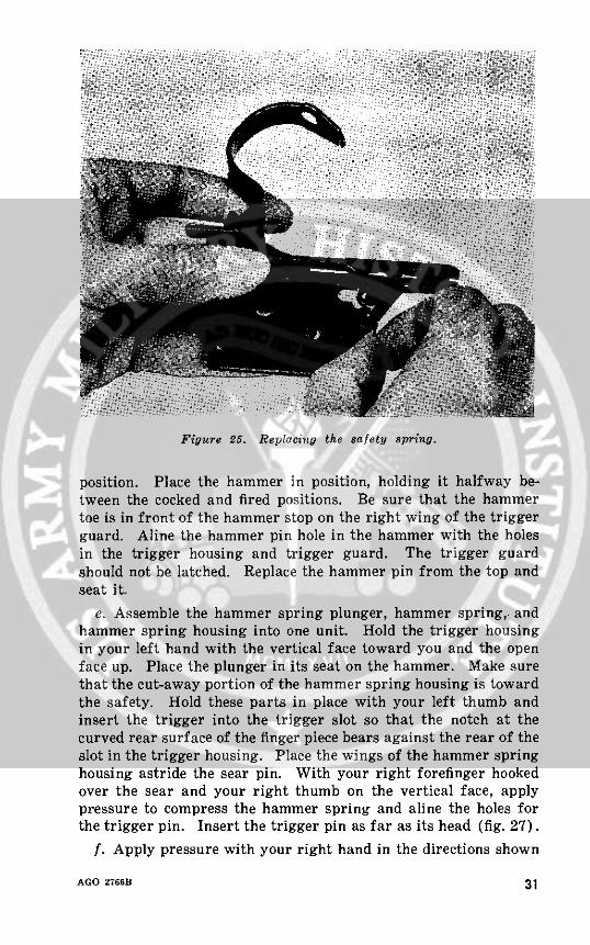
Figure 25. Replacing the safety spring.
position. Place the hammer in position, holding it halfway be-tween the cocked and fired positions. Be sure that the hammertoe is in front of the hammer stop on the right wing of the triggerguard. Aline the hammer pin hole in the hammer with the holesin the trigger housing and trigger guard. The trigger guardshould not be latched. Replace the hammer pin from the top andseat it.
e. Assemble the hammer spring plunger, hammer spring, andhammer spring housing into one unit. Hold the trigger housingin your left hand with the vertical face toward you and the openface up. Place the plunger in its seat on the hammer. Make surethat the cut-away portion of the hammer spring housing is towardthe safety. Hold these parts in place with your left thumb andinsert the trigger into the trigger slot so that the notch at thecurved rear surface of the finger piece bears against the rear of theslot in the trigger housing. Place the wings of the hammer springhousing astride the sear pin. With your right forefinger hookedover the sear and your right thumb on the vertical face, applypressure to compress the hammer spring and aline the holes forthe trigger pin. Insert the trigger pin as far as its head (fig. 27).
f. Apply pressure with your right hand in the directions shown
AGO 2766B 31
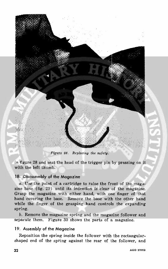
Figure 26. Replacing the safety.
in figure 28 and seat the head of the trigger pin by pressing on itwith the left thumb.
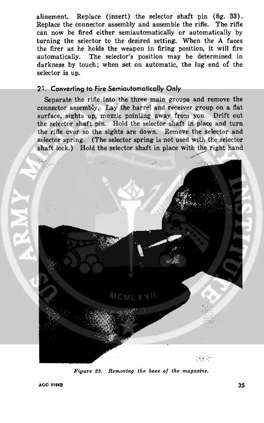
18. Disassembly of the Magazinea. Use the point of a cartridge to raise the front of the maga-
zine base (fig. 29) until its indention is clear of the magazine.Grasp the magazine with either hand, with one finger of thathand covering the base. Remove the base with the other handwhile the finger of the grasping hand controls the expandingspring.
b. Remove the magazine spring and the magazine follower andseparate them. Figure 30 shows the parts of a magazine.
19. Assembly of the MagazineReposition the spring inside the follower with the rectangular-
shaped end of the spring against the rear of the follower, and
32 AGO 2766B
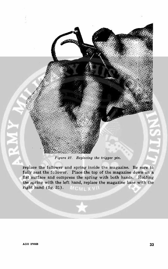
Figure 27. Replacing the trigger pin.
replace the follower and spring inside the magazine. Be sure tofully seat the follower. Place the top of the magazine down on aflat surface and compress the spring with both hands. Holdingthe spring with the left hand, replace the magazine base with theright hand (fig. 31).
AGO 2766B 33
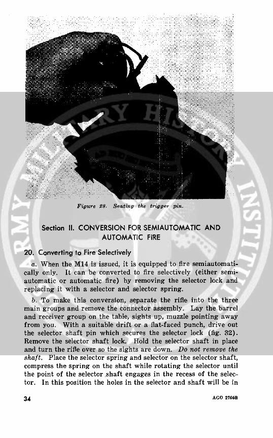
Figure 28. Seating the trigger pin.
Section II. CONVERSION FOR SEMIAUTOMATIC ANDAUTOMATIC FIRE
20. Converting to Fire Selectivelya. When the M14 is issued, it is equipped to fire semiautomati-
cally only. It can be converted to fire selectively (either semi-automatic or automatic fire) by removing the selector lock andreplacing it with a selector and selector spring.
b. To make this conversion, separate the rifle into the threemain groups and remove the connector assembly. Lay the barreland receiver group on the table, sights up, muzzle pointing awayfrom you. With a suitable drift or a flat-faced punch, drive outthe selector shaft pin which secures the selector lock (fig. 32).Remove the selector shaft lock. Hold the selector shaft in placeand turn the rifle over so the sights are down. Do not remove theshaft. Place the selector spring and selector on the selector shaft,compress the spring on the shaft while rotating the selector untilthe point of the selector shaft engages in the recess of the selec-tor. In this position the holes in the selector and shaft will be in
34 AGO 2766B
alinement. Replace (insert) the selector shaft pin (fig. 33).Replace the connector assembly and assemble the rifle. The riflecan now be fired either semiautomatically or automatically byturning the selector to the desired setting. When the A facesthe firer as he holds the weapon in firing position, it will fireautomatically. The selector's position may be determined indarkness by touch; when set on automatic, the lug end of theselector is up.
21. Converting to Fire Semiautomatically OnlySeparate the rifle into the three main groups and remove the
connector assembly. Lay the barrel and receiver group on a flatsurface, sights up, muzzle pointing away from you. Drift outthe selector shaft pin. Hold the selector shaft in place and turnthe rifle over so the sights are down. Remove the selector andselector spring. (The selector spring is not used with the selectorshaft lock.) Hold the selector shaft in place with the right hand
Figure 29. Removing the base of the magazine.
AGO 276B 35
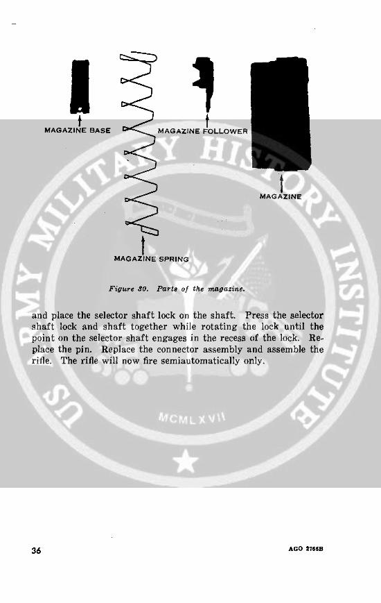
MAGAZINE BASE t MAGAZINE FOLLOWER
MAGAZINE
MAGAZINE SPRING
Figure 30. Parts of the magazine.
and place the selector shaft lock on the shaft. Press the selectorshaft lock and shaft together while rotating the lock until thepoint on the selector shaft engages in the recess of the lock. Re-place the pin. Replace the connector assembly and assemble therifle. The rifle will now fire semiautomatically only.
36 AGO 2766B

Figure 31. Replacing the magazine base.
AGO 2766B 37

SiP.
I-
38 AGO 266B_
- M X~~~~~~~1
-- ~~~~~~

Figure 13. Replacing the selector shaft pin.
AGO 2766B 39
CHAPTER 3OPERATION AND FUNCTIONING
Section I. OPERATION
22. Loading the Magazinea. Hold the magazine as shown in figure 34. Insert the rounds
with the bullet ends toward the front of the magazine (front endhas square hole).
b. To load the magazine with a filler, slide the filler over thetop rear portion of the magazine. Insert a 5-round magazinecharger in the filler. Place either thumb on the top round andpush the 5 rounds into the magazine. Remove the magazinecharger and repeat the process until 20 rounds have been loadedinto the magazine, then remove the magazine filler.
23. Loading the Riflea. Single Round (No Magazine in Rifle).
(1) Place the safety in the safe position (inside the triggerguard).
(2) Pull the operating rod all the way to the rear and pressin the bolt lock with your right thumb. Hold the muzzlebelow the horizontal; place a round into the chamberand seat it with the thumb. Pull back on the operatingrod handle and release it; the bolt will go forward.
b. Single Round (Magazine in Rifle). To load a single roundwith the magazine in the weapon, place the safety in the safeposition and seat a round in the chamber. Next, depress themagazine follower with the right thumb and, at the same time,press back on the operating rod handle with the edge of the hand.This will release the bolt lock and allow the bolt to go forward.
c. Loaded Magazine.(1) Place the safety in the safe position.(2) Insert a loaded magazine into the magazine well, top
front first, until the operating rod spring guide engagesthe magazine (fig. 35(1)), then pull backward and up-ward until the magazine latch snaps into position (fig.35(2)). A click will be heard which indicates that the
40 AGO 2766B
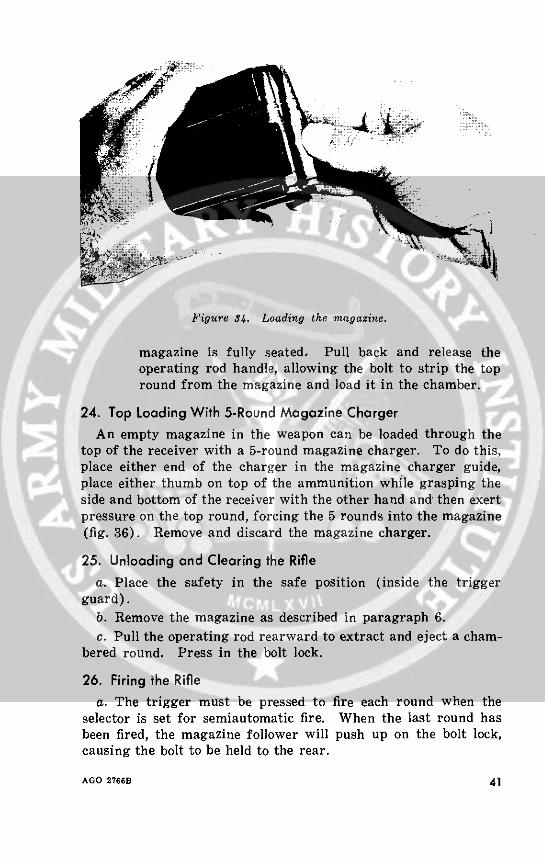
Figure 34. Loading the magazine.
magazine is fully seated, Pull back and release theoperating rod handle, allowing the bolt to strip the topround from the magazine and load it in the chamber.
24. Top Loading With 5-Round Magazine ChargerAn empty magazine in the weapon can be loaded through the
top of the receiver with a 5-round magazine charger. To do this,place either end of the charger in the magazine charger guide,place either thumb on top of the ammunition while grasping theside and bottom of the receiver with the other hand and then exertpressure on the top round, forcing the 5 rounds into the magazine(fig. 36). Remove and discard the magazine charger.
25. Unloading and Clearing the Riflea. Place the safety in the safe position (inside the trigger
guard).b. Remove the magazine as described in paragraph 6.c. Pull the operating rod rearward to extract and eject a cham-
bered round. Press in the bolt lock.
26. Firing the Riflea. The trigger must be pressed to fire each round when the
selector is set for semiautomatic fire. When the last round hasbeen fired, the magazine follower will push up on the bolt lock,causing the bolt to be held to the rear.
AGO 2766B 41
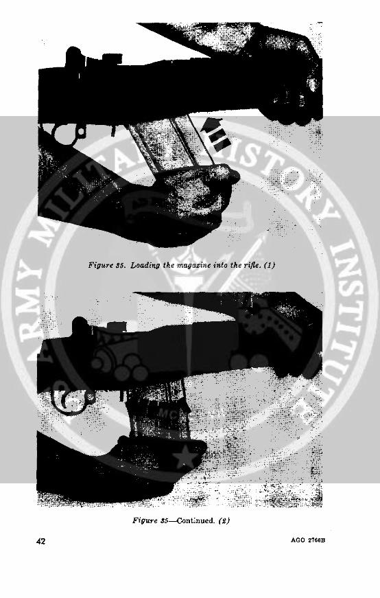
Figure 35. Loading the magazine into the rifle. (1)
Figure 35--Continued. (2)
42 AGO 27668
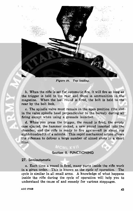
Figure 36. Top loading.
b. When the rifle is set for automatic fire, it will fire as long asthe trigger is held to the rear and there is ammunition in themagazine. When the last round is fired, the bolt is held to therear by the bolt lock.
c. The spindle valve must remain in the open position (the slotin the valve spindle head perpendicular to the barrel) during allfiring except when using a grenade launcher.
d. When you press the trigger, the round is fired, the emptycase ejected, the hammer cocked, a new round inserted into thechamber, and the rifle is ready to fire again-all in about oneeight-hundredth of a minute. This rapid mechanical action allowsthe rifleman to deliver a large number of aimed shots in a shorttime.
Section II. FUNCTIONING
27. Semiautomatic
a. Each time a round is fired, many parts inside the rifle workin a given order. This is known as the cycle of operation. Thecycle is similar in all small arms. A knowledge of what happensinside the rifle during the cycle of operation will help you tounderstand the cause of and remedy for various stoppages.
AGO 2766B 43
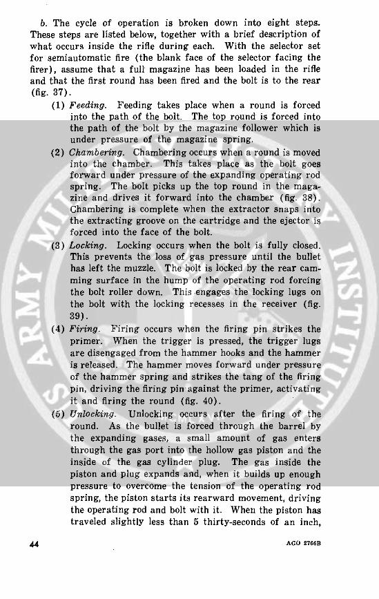
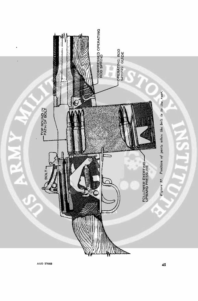
b. The cycle of operation is broken down into eight steps.These steps are listed below, together with a brief description ofwhat occurs inside the rifle during each. With the selector setfor semiautomatic fire (the blank face of the selector facing thefirer), assume that a full magazine has been loaded in the rifleand that the first round has been fired and the bolt is to the rear(fig. 37).
(1) Feeding. Feeding takes place when a round is forcedinto the path of the bolt. The top round is forced intothe path of the bolt by the magazine follower which isunder pressure of the magazine spring.
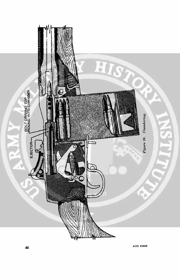
(2) Chambering. Chambering occurs when a round is movedinto the chamber. This takes place as the bolt goesforward under pressure of the expanding operating rodspring. The bolt picks up the top round in the maga-zine and drives it forward into the chamber (fig. 38).Chambering is complete when the extractor snaps intothe extracting groove on the cartridge and the ejector isforced into the face of the bolt.
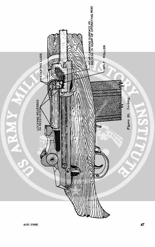
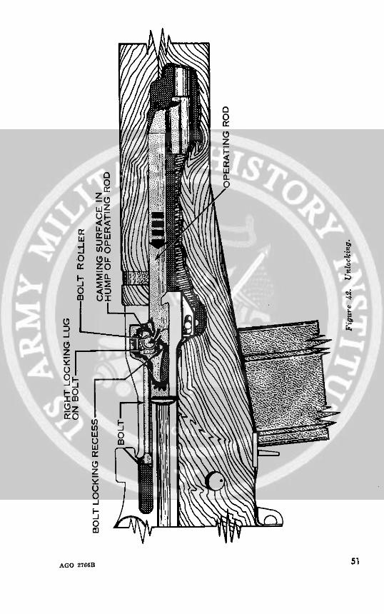
(3) Locking. Locking occurs when the bolt is fully closed.This prevents the loss of gas pressure until the bullethas left the muzzle. The bolt is locked by the rear cam-ming surface in the hump of the operating rod forcingthe bolt roller down. This engages the locking lugs onthe bolt with the locking recesses in the receiver (fig.39).
(4) Firing. Firing occurs when the firing pin strikes theprimer. When the trigger is pressed, the trigger lugsare disengaged from the hammer hooks and the hammeris released. The hammer moves forward under pressureof the hammer spring and strikes the tang of the firingpin, driving the firing pin against the primer, activatingit and firing the round (fig. 40).
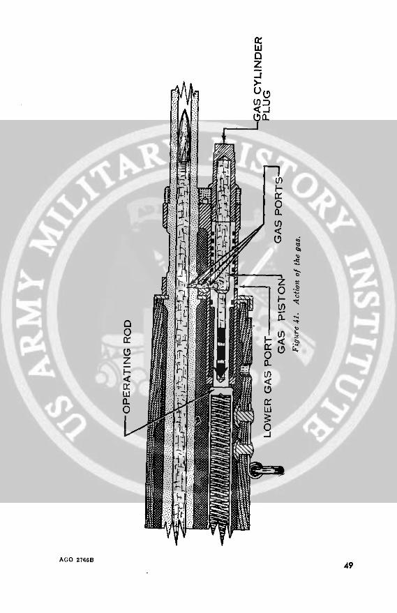
(5) Unlocking. Unlocking occurs after the firing of theround. As the bullet is forced through the barrel bythe expanding gases, a small amount of gas entersthrough the gas port into the hollow gas piston and theinside of the gas cylinder plug. The gas inside thepiston and plug expands and, when it builds up enoughpressure to overcome the tension of the operating rodspring, the piston starts its rearward movement, drivingthe operating rod and bolt with it. When the piston hastraveled slightly less than 5 thirty-seconds of an inch,
44 AGO 2766B
0z
0~~~~~~~~.
ww0 w
C13~~~~~~~~4
A'IA
Ao 27868 40
I O~~~~W
wui
AGO 27668 a
I0
zo a ~l ~ ~ S ' '.
46 AGO 1G6B
on-
0
C
uz D! ...a..., °
AGO Z766B 47

tw 5
w B
< 3h o 7
A 2 6
48
m z~~~~~~~~~~~~~~~c lb
it0z
U(D
co ~;
cnn
II
05 0
/;CL I ~
AGO 2766B49
the gas ports are no longer alined and no more gas canenter the piston (fig. 41). The remaining gas in thebarrel follows the bullet out of the muzzle. There isabout three-eighths of an inch rearward movement of theoperating rod before unlocking begins. This is a safetyfeature to insure that all the unneeded gas has gone outthe barrel before unlocking begins. After the operatingrod has moved this short distance, the camming sur-face inside its hump forces the bolt roller upward, dis-engaging the locking lugs on the bolt from the lockingrecesses in the receiver. The bolt is thus unlocked andready to be moved to the rear (fig. 42). Any gas thatis left in the gas cylinder or piston after the bolt is allthe way to the rear escapes through the lower gas portin the cylinder.
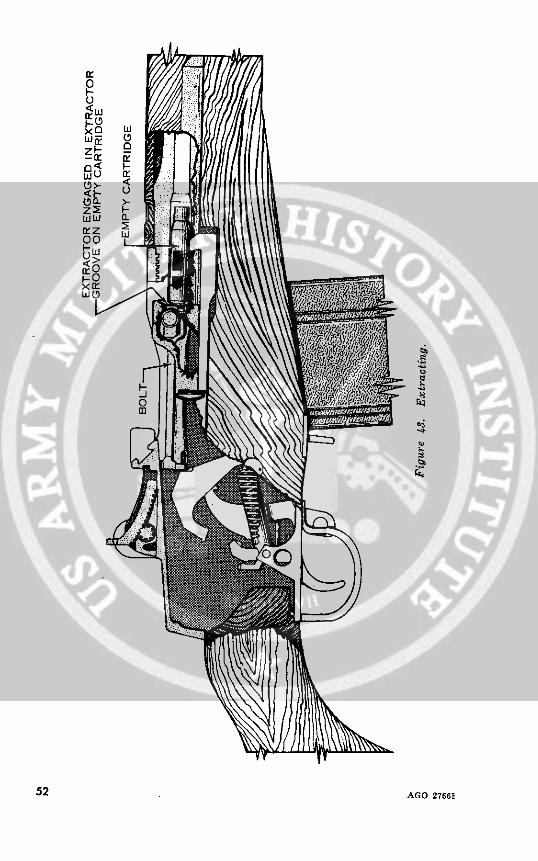
(6) Extracting. Extracting is pulling the empty cartridgefrom the chamber. As the bolt unlocks, slow initialextraction takes place. When the bolt is moved to therear, it pulls the empty cartridge with it (fig. 43).
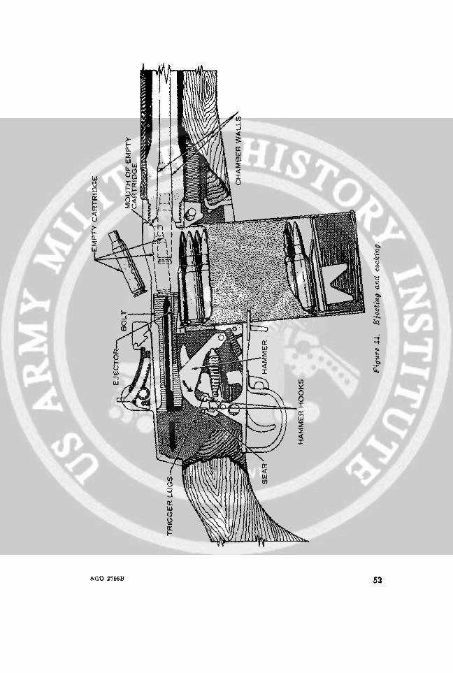
(7) Ejecting. Ejecting is throwing the empty cartridge outof and away from the receiver. As soon as the bolt haswithdrawn the empty cartridge case clear of the cham-ber, the force of the ejector spring and plunger pushesthe bottom edge of the cartridge base away from thebolt face. This causes the front (neck) of the cartridgecase to move upwards and to the right. The rapidrearward movement of the bolt causes the cartridgecase to strike the angle on the lower right corner of themagazine charger guide as the cartridge case is turnedsideways. The rapid forward movement of the operat-ing rod handle causes the leading edge of the "caimminghump" to strike the cartridge case with the angle onthe outer edge of this "hump" continuing the movementof the empty case to the right front. When the lastround has been fired and the bolt is held in the rear-ward position by the bolt lock, the ejector propels thelast round out and away from the receiver (fig. 44).
(8) Cocking. Cocking occurs when the hammer is forcedinto the proper position for firing the next round. Thishappens as the bolt continues to the rear. The rear endof the bolt forces the hammer back and rides over it.The hammer is caught by the sear if the trigger is stillheld to the rear, but by the trigger lugs if the triggerpressure has been released (fig. 44).
50 AGO 2766B
0~~~~~~~~~
ZO
X o
wt
wow
0 LLIr z 0 Ill /~~~~~
~~~~~~~~~~1 ~ ~ ~ ~ ~ ~ ~ ,0
5z
AO2B
-i~~~~~~~~~~~~~~~~~~~~~~~~~~~~~~~~~~~~~~~~~~~~~.I--~~ '0
o(z
AGO 2766B 5
z~o
~Z&
O0~-0
<LI
xc Lii
xn
U05~>-<
Q~z 2
z2 F-
F-o
52 AGO 27661
U -Z
Or~r
gt~~~~~~~~~~
ah >1W. 8
AGO 2T6Sf 53
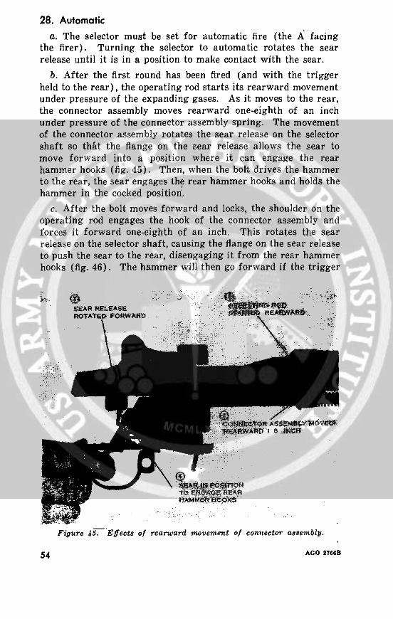
28. Automatica. The selector must be set for automatic fire (the A facing
the firer). Turning the selector to automatic rotates the searrelease until it is in a position to make contact with the sear.
b. After the first round has been fired (and with the triggerheld to the rear), the operating rod starts its rearward movementunder pressure of the expanding gases. As it moves to the rear,the connector assembly moves rearward one-eighth of an inchunder pressure of the connector assembly spring. The movementof the connector assembly rotates the sear release on the selectorshaft so that the flange on the sear release allows the sear tomove forward into a position where it can engage the rearhammer hooks (fig. 45). Then, when the bolt drives the hammerto the rear, the sear engages the rear hammer hooks and holds thehammer in the cocked position!.
c. After the bolt moves forward and locks, the shoulder on theoperating rod engages the hook of the connector assembly andforces it forward one-eighth of an inch. This rotates the searrelease on the selector shaft, causing the flange on the sear releaseto push the sear to the rear, disengaging it from the rear hammerhooks (fig. 46). The hammer will then go forward if the trigger
a ,@ .0 -- .:4 0"
SEAR RELEASEROTATED FORWAROD
Figure 45. Effects of rearward movement of connector assembly.
54 AGO 2766B
0~~~~~~~~~~~~~~~~~~~~,c \2TiLees;'a
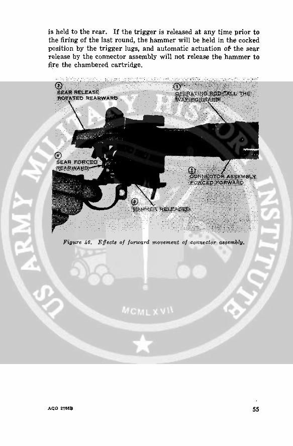
is held to the rear. If the trigger is released at any time prior tothe firing of the last round, the hammer will be held in the cockedposition by the trigger lugs, and automatic actuation of the searrelease by the connector assembly will not release the hammer tofire the chambered cartridge.
SETA7EREAtWARD
Figure 46. Effects of forward movement of connector assembly.
AGO 2766D 55
CHAPTER 4STOPPAGES AND IMMEDIATE ACTION
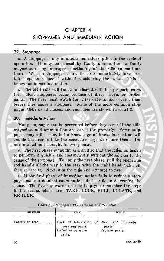
29. Stoppagea. A stoppage is any unintentional interruption in the cycle of
operation. It may be caused by faulty ammunition, a faultymagazine, or by improper functioning of the rifle (a malfunc-tion). When a stoppage occurs, the firer immediately takes cer-tain steps to reduce it without considering the cause. This isknown as immediate action.
b. The M14 rifle will function efficiently if it is properly caredfor. Most stoppages occur because of dirty, worn, or brokenparts. The firer must watch for these defects and correct thembefore they cause a stoppage. Some of the more common stop-pages, their usual causes, and remedies are shown in chart 2.
30. Immediate ActionMany stoppages can be prevented before they occur if the rifle,
magazine, and ammunition are cared for properly. Some stop-pages may still occur, but a knowledge of immediate action willenable the firer to take the necessary steps to reduce them. Im-mediate action is taught in two phases.
a. The first phase is taught as a drill so that the rifleman learnsto perform it quickly and instinctively without thought as to thecause of the stoppage. To apply the first phase, pull the operatingrod handle all the way to the rear with the right hand, palm up,then release it. Next, aim the rifle and attempt to fire.
b. If the first phase of immediate action fails to reduce a stop-page, make a detailed examination of the rifle to determine thecause. The five key words used to help you remember the stepsin the second phase are: TAKE, LOOK, PULL, LOCATE, andREDUCE.
Chart 2. Stoppages: Their Causes and Remedies
Stowppaes Caxae Remedy
Failure to feed-_______ Lack of lubrication of Clean and lubricateoperating parts. parts.
Defective or worn Replace parts.parts.
56 AGO 2.766B
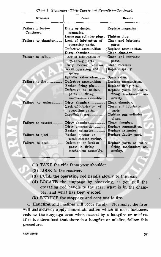
Chart 2. Stoppages: Their Causes and Remedies-Continued.
Stoppages Cause Remedy
Failure to feed- Dirty or dented Replace magazine.Continued magazine.
Loose gas cylinder plug_ Tighten plug.Failure to chamber __ Lack of lubrication of Clean and lubricate
operating parts. parts.Defective ammunition__. Replace ammunition.Dirty chamber --__ . Clean chamber.
Failure to lock -- ______ Lack of lubrication of Clean and lubricateoperating parts. parts.
Dirty locking recesses Clean recesses.Weak operating rod Replace spring.
spring.Spindle valve closed___ Open valve.
Failure to fire -- ______ Defective ammunition__. Replace ammunition.Broken firing pin _____ Replace firing pin.Defective or broken Replace parts or entire
parts in firing firing mechanism as-mechanism assembly. sembly.
Failure to unlock--_____ Dirty chamber .--_____ Clean chamber.Lack of lubrication of Clean and lubricate
operating parts. parts.Insufficient gas --____ Tighten gas cylinder
plugs.Failure to extract ----- Dirty chamber ........ Clean chamber.
Dirty ammunition______ - Replace ammunition.Broken extractor .-.... Replace extractor.
Failure to eject ________ Broken ejector or Replace faulty part.weak ejector spring.
Failure to cock _______ Defective or broken Replace parts or entireparts in firing firing mechanism as-mechanism assembly. sembly.
(1) TAKE the rifle from your shoulder.(2) LOOK in the receiver.(3) PULL the operating rod handle slowly to the rear.(4) LOCATE the stoppage by observing, as you pull the
operating rod handle to the rear, what is in the cham-ber, and what has been ejected.
(5) REDUCE the stoppage and continue to fire.
c. Hangfires and misfires will occur rarely. Normally, the firerwill instinctively apply immediate action which in most instancesreduces the stoppage even when caused by a hangfire or misfire.If it is determined that there is a hangfire or misfire, follow thisprocedure.
AGO 2766B 57

(1) Remove the magazine.(2) Place the safety in the safe position.(3) Wait 10 seconds.(4) Apply immediate action as stated in b above.
d. The normal cause of a misfire is faulty ammunition. There-fore, further use of ammunition from that lot should be suspendedand reported to ordnance for withdrawal and replacement.
58 AGO 2766B
CHAPTER 5
MAINTENANCE
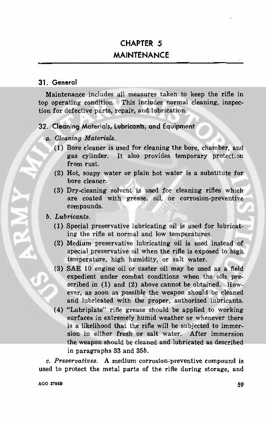
31. General
Maintenance includes all measures taken to keep the rifle intop operating condition. This includes normal cleaning, inspec-tion for defective parts, repair, and lubrication.
32. Cleaning Materials, Lubricants, and Equipmenta. Cleaning Materials.
(1) Bore cleaner is used for cleaning the bore, chamber, andgas cylinder. It also provides temporary protectionfrom rust.
(2) Hot, soapy water or plain hot water is a substitute forbore cleaner.
(3) Dry-cleaning solvent is used for cleaning rifles whichare coated with grease, oil, or corrosion-preventivecompounds.
b. Lubricants.(1) Special preservative lubricating oil is used for lubricat-
ing the rifle at normal and low temperatures.(2) Medium preservative lubricating oil is used instead of
special preservative oil when the rifle is exposed to hightemperature, high humidity, or salt water.
(3) SAE 10 engine oil or caster oil may be used as a fieldexpedient under combat conditions when the oils pre-scribed in (1) and (2) above cannot be obtained. How-.ever, as soon as possible the weapon should be cleanedand lubricated with the proper, authorized lubricants.
(4) "Lubriplate" rifle grease should be applied to workingsurfaces in extremely humid weather or whenever thereis a likelihood that the rifle will be subjected to immer-sion in either fresh or salt water. After immersionthe weapon should be cleaned and lubricated as describedin paragraphs 33 and 35b.
c. Preservatives. A medium corrosion-preventive compound isused to protect the metal parts of the rifle during storage, and
AGO 276es 59
raw linseed oil is applied to the wooden parts to prevent theirdrying.
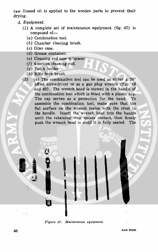
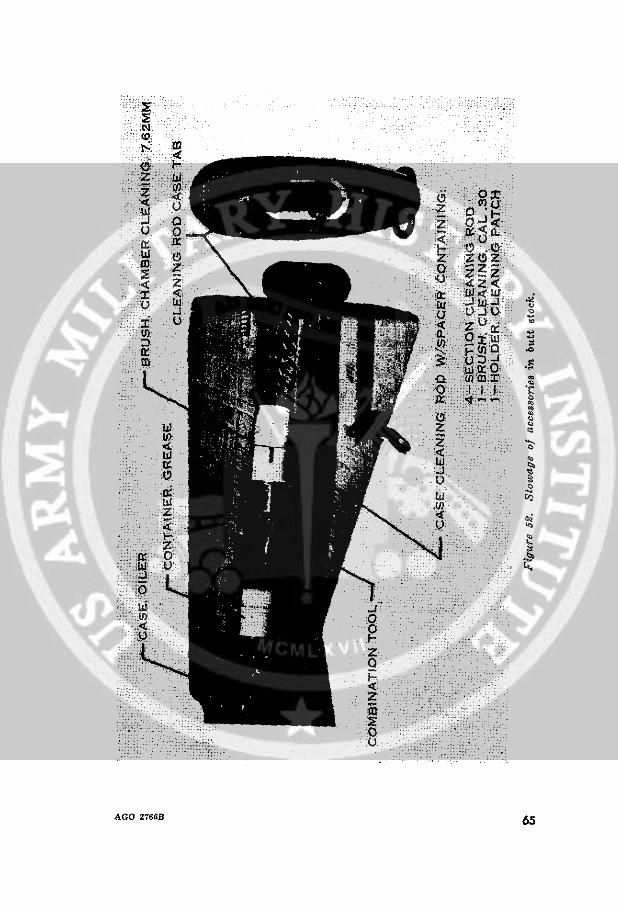
d. Equipment.(1) A complete set of maintenance equipment (fig. 47) is
composed of-(a) Combination tool.(b) Chamber cleaning brush.(c) Oiler case.(d) Grease container.(e) Cleaning rod case w/spacer.(f) 4-section cleaning rod.(g) Patch holder.(h) Rifle bore brush.
(2) (a) The combination tool can be used as either a 200offset screwdriver or as a gas plug wrench (figs. 48and 49). The wrench head is stowed in the handle ofthe combination tool which is fitted with a plastic cap.The cap serves as a protection for the hand. Toassemble the combination tool, make sure that theflat surface on the wrench mates with the rivet inthe handle. Insert the wrench head into the handleuntil the retaining ring makes contact, then firmlypush the wrench head in until it is fully seated. The
111 *
I
Figure 47. Maintenance equipment.
60 AGO 2766B
screwdriver blade is an extension of the wrench head.Although the tool may be used without the cap, it isbetter to use it to prevent the slotted end of the handlefrom digging into the palm of the hand.
(b) The handle of the combination tool is also used as thecleaning rod handle. To do this, allow the cleaningrod extension of the tool to fall from the tool handleso that it hangs perpendicular. Assemble the foursections of the cleaning rod and screw into thethreaded hole in the cleaning rod extension. Eitherthe bore brush or the cleaning patch holder may beattached to the end of the cleaning rod.
(c) The plastic oiler case (fig. 50) holds about 7 cubiccentimeters of oil. The case is closed with a screwcap which has a stem (applicator) attached that isused to apply oil drop by drop. The cap is fitted witha gasket to prevent oil leakage.
(d) The grease container (fig. 51) is also a plastic unit.It consists of a standard grease cup with a cap. Oneend of the grease cup cap screws onto the grease cup.The other end fits over the end of the handle of thecombination tool (fig. 47) for storage. Inside thecap is a bent stem (applicator) that is used to applythe grease. The stem is bent to make it easier to
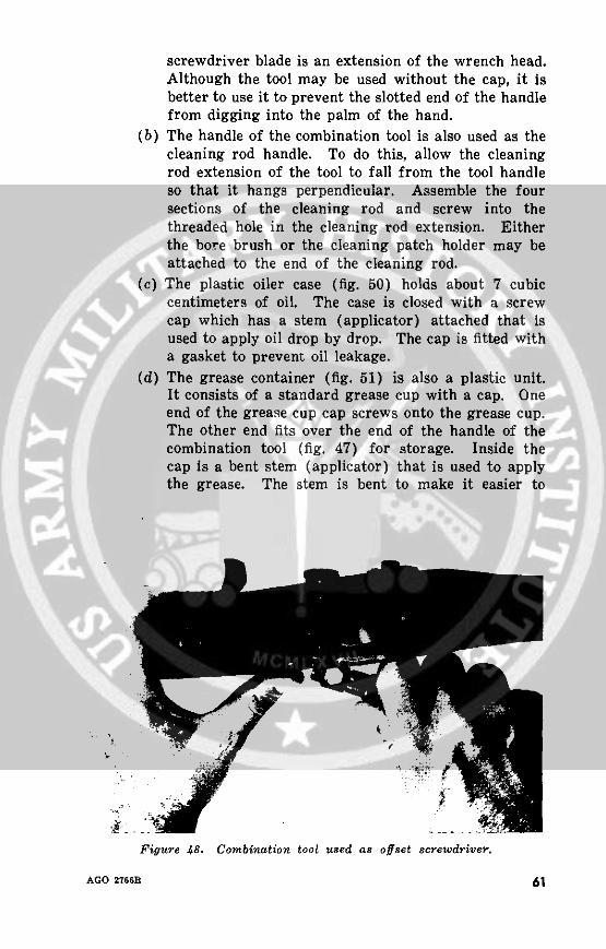
Figure 48. Combination tool used as offset screwdriver.
AGO 2766B 61
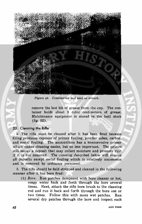
Figure 49. Combination tool used as wrench.
remove the last bit of grease from the cup. The con-tainer holds about 3 cubic centimeters of grease.Maintenance equipment is stored in the butt stock(fig. 52).
33. Cleaning the Riflea. The rifle must be cleaned after it has been fired because
firing produces deposits of primer fouling, powder ashes, carbon,and metal fouling. The ammunition has a noncorrosive primerwhich makes cleaning easier, but no less important. The primerstill leaves a deposit that may collect moisture and promote rustif it is not removed. The cleaning described below will removeall deposits except metal fouling which is relatively uncommonand is removed by ordnance personnel.
b. The rifle should be field stripped and cleaned in the followingmanner after it has been fired:
(1) Bore. Run patches dampened with bore cleaner or hot,soapy water back and forth through the bore severaltimes. Next, attach the rifle bore brush to the cleaningrod and run it back and forth through the bore one ortwo times. Follow this with more wet patches. Runseveral dry patches through the bore and inspect each
62 AGO 2766B
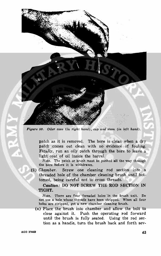
Figure 50. Oiler case (in right hand), cap and stem (in left hand).
patch as it is removed. The bore is clean when a drypatch comes out clean with no evidence of fouling.Finally, run an oily patch through the bore to leave alight coat of oil inside the barrel.
Note. The patch or brush must be pushed all the way throughthe bore before it is withdrawn.
(2) Chamber. Screw one cleaning rod section into athreaded hole of the chamber cleaning brush until bot-tomed, being careful not to cross threads.
Caution: DO NOT SCREW THE ROD SECTION INTIGHT.
Note. There are four threaded holes in the brush unit. Donot use a hole whose threads have been stripped. When all fourholes are stripped, get a new chamber cleaning brush.
(a) Place the brush into chamber and allow the bolt toclose against it. Push the operating rod forwarduntil the brush is fully seated. Using the rod sec-tion as a handle, turn the brush back and forth sev-
AGO 2766B 63

Figure 51. Grease container (in right hand), cap and stem (in left hand).
eral times (clockwise and counterclockwise) about1000 (fig. 53).
(b) To remove the brush from the chamber, grip the rodas shown in figure 54 as close to the bolt as possible(without gripping the operating rod handle). Withthe bolt remaining against the brush, pull the unitrearward sharply until the brush clears the chamber.Lock the bolt in the rearmost position and remove thebrush.
(c) To wipe the chamber free of oil, wrap a cleaningpatch around the brush, insert it in the chamber, and
64 AGO 2766B
, .o.~~~~~~
'0; W I; \'
:t~ tf (z¢ft -,\ �: n f':: w~~
J~~~~~~~~~~~~~~ V
- : <1.: --: S f A-::fD
d'.':.tv,: : z u; :: . z 0 -- ., ;
%.-, m _· : O1 f . .0005 ?- f: .-:
. _.
__~~~~~~~~~~~~~~~~~~~~~~~~~~~~~~~~~~~~~~~~~C
,,,i t.\ 0 f' f\.
t
o~~~~~~~~~
65
AGO ZTS6B
AGO 2761 6
AGO 2766B ~5
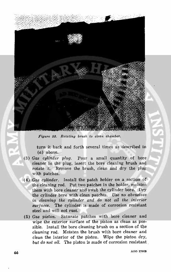
Figure 53. Rotating brush to clean chamber.
turn it back and forth several times as described in(a) above.
(3) Gas cylinder plug. Pour a small quantity of borecleaner in the plug, insert the bore cleaning brush androtate it. Remove the brush, clean and dry the plugwith patches.
(4) Gas cylinder. Install the patch holder on a section ofthe cleaning rod. Put two patches in the holder, moistenthem with bore cleaner and swab the cylinder bore. Drythe cylinder bore with clean patches. Use no abrasivesin cleaning the cylinder and do not oil the interiorsurfaces. The cylinder is made of corrosion resistantsteel and will not rust.
(5) Gas piston. Saturate patches with bore cleaner andwipe the exterior surface of the piston as clean as pos-sible. Install the bore cleaning brush on a section of thecleaning rod. Moisten the brush with bore cleaner andclean the interior of the piston. Wipe the piston dry,but do not oil. The piston is made of corrosion resistant
66 AGO 2766B
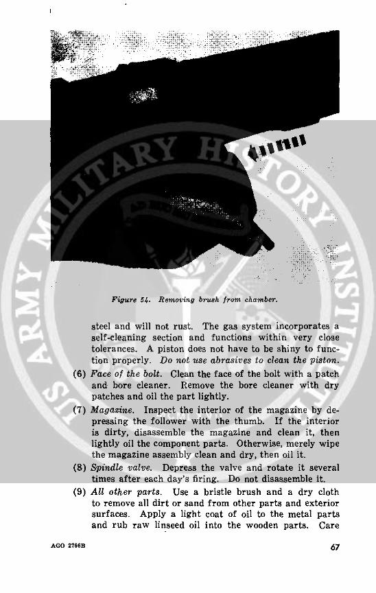
Figure 54. Removing brush from chamber.
steel and will not rust. The gas system incorporates aself-cleaning section and functions within very closetolerances. A piston does not have to be shiny to func-tion properly. Do not use abrasives to clean the piston.
(6) Face of the bolt. Clean the face of the bolt with a patchand bore cleaner. Remove the bore cleaner with drypatches and oil the part lightly.
(7) Magazine. Inspect the interior of the magazine by de-pressing the follower with the thumb. If the interioris dirty, disassemble the magazine and clean it, thenlightly oil the component parts. Otherwise, merely wipethe magazine assembly clean and dry, then oil it.
(8) Spindle valve. Depress the valve and rotate it severaltimes after each day's firing. Do not disassemble it.
(9) All other parts. Use a bristle brush and a dry clothto remove all dirt or sand from other parts and exteriorsurfaces. Apply a light coat of oil to the metal partsand rub raw linseed oil into the wooden parts. Care
AGO 2766B 67
must be taken to prevent linseed oil from getting onmetal parts, or these parts will become sticky or gummy.
c. The rifle must be cleaned no later than the evening of theday it is fired. For three consecutive days thereafter check forevidence of fouling by running a clean patch through the boreand inspecting it. The bore should then be lightly oiled.
34. Normal Maintenance
a. The rifle should be inspected daily for evidence of rust andgeneral appearance. A light coat of oil should be maintained onall metal parts, except the gas piston, interior of the gas cylinder,and the gas plug.
b. The daily inspection should also reveal any defects such asburred, worn, or cracked parts. Defects should be reported tothe armorer for correction.
c. A muzzle plug should never' be used on the rifle. It causesmoisture to collect in the bore which causes the bore to rust.
35. Special Maintenance
a. Before firing the rifle, the bore and the chamber should becleaned and dried. A light coat of oil should be placed on allother metal parts except those which come in contact with am-munition (and except the gas piston, interior of the gas cylinder,and the gas plug).
b. Rifle grease should be applied before firing to the parts indi-cated in figure 55. This is particularly important when the rifleis exposed to rain or salt water. A small amount of grease istaken up on the stem of the grease container cap and is appliedat each place. Rifle grease is not used in extremely cold tempera-tures or when the rifle is exposed to extremes of sand and dust(c and e below).
c. In cold climates (temperatures below freezing) the rifle mustbe kept free of moisture and excess oil. Moisture and excess oilon the working parts cause them to operate sluggishly or failcompletely. The rifle must be disassembled and wiped with aclean dry cloth. Dry cleaning solvent may be used if necessaryto remove oil or grease. Parts that show signs of wear may bewiped with a patch lightly dampened with special preservativelubricating oil. It is best to keep the rifle as close as possible tooutside temperatures at all times to prevent the collection ofmoisture which occurs when cold metal comes in contact withwarm air. If the rifle is brought into a warm room, it should
68 AGO 2766B
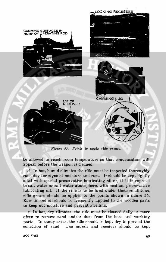
-NLOCKING RECESSES
HUMP OF OPERATING ROD
BOLTCAMMING LUG
LIP OfrECEIVER
Figure 55. Points to apply rifle grease.
be allowed to reach room temperature so that condensation willappear before the weapon is cleaned.
d. In hot, humid climates the rifle must be inspected thoroughlyeach day for signs of moisture and rust. It should be kept lightlyoiled with special preservative lubricating oil or, if it is exposedto salt water or salt water atmosphere, with medium preservativelubricating oil. If the rifle is to be fired under these conditions,rifle grease should be applied to the points shown in figure 55.Raw linseed oil should be frequently applied to the wooden partsto keep out moisture and prevent swelling.
e. In hot, dry climates, the rifle must be cleaned daily or moreoften to remove sand and/or dust from the bore and workingparts. In sandy areas, the rifle should be kept dry to prevent thecollection of sand. The muzzle and receiver should be kept
AGO 2766B 69

covered during sand and dust storms. Wooden parts must be keptoiled with raw linseed oil to prevent drying. The rifle should berelubricated when sandy or dusty conditions decrease or whenit begins to show rust.
f. Special instructions on caring for the rifle when it is subjectto nuclear, biological, or chemical contamination may be foundin FM 21-40.
36. Storagea. Preparation for Storage. Thoroughly clean and then com-
pletely dry the bore, all parts of the mechanism, and the exteriorof the weapon. In damp climates, make sure that the rags usedfor cleaning are dry. After metal parts have been dried, be care-ful not to touch them with the bare hands. Coat them with eithermedium preservative lubricating oil or, if the weapon is to remainin storage for a very long time, medium rust preventive com-pound. Before placing the rifle in the packing chest, paint theweapon supports for the butt and muzzle with rust preventivecompound. Never store a rifle in a cloth or similar cover andnever plug the bore. Such articles collect moisture that causesthe rifle to-rust.
b. Cleaning When Rifles Have Been in Long-Term Storage.Weapons received from long-term storage usually have a coat oflight or medium preservative oil and are inclosed in a volatilecorrosion inhibitor (VCI) type, sealed aluminum foil, barrier typebag. These weapons can be fired as soon as the VCI tube is re-moved from the bore, but they should normally be cleaned andlubricated as prescribed in paragraphs 33-35.
70 AGO 2766B
CHAPTER 6
AMMUNITION
37. GeneralThe M14 rifle fires several types of ammunition. The rifleman
should be able to recognize them and know which type is bestfor certain targets. He should also know how to care for theammunition.
a. Figure 56 shows the parts of a typical cartridge.
b. The term "bullet" refers only to a small arms projectile; theterm "ball" was originally used to describe the ball-shaped bulletof very early small arms ammunition. The term "ball ammuni-tion" now refers to a cartridge with a general purpose solid core.bullet intended for use against personnel and material targets.
38. Description
The four types of ammunition are easily identified by theirindividual markings.
a. Ball. The M59 ball cartridge has a boat-tailed bullet (therear of the bullet is tapered) and weighs 147 grains. It is com-posed of a gilding metal jacket, a soft steel core, a lead antimonybase, and a point filler. The tip of the bullet is not colored.
b. Armor Piercing. The M61 armor piercing cartridge has aboat-tailed bullet, weighs 147 grains, and is composed of a gildingmetal-clad jacket, a hardened steel core, a lead antimony base,and a point filler. The tip of the round is painted black.
c. Tracer. The M62 tracer cartridge has a boat-tailed bulletand weighs 141 grains. It is composed of a gilding metal or gild-ing metal-clad steel jacket, a lead antimony core, a tracer, sub-igniter and igniter composition, and a closure cap. The tip of theround is painted orange.
d. Dummy. The M63 dummy cartridge is identifiable by thesix longitudinal flutes in the case.
39. Ballistic Data
The approximate maximum range and average muzzle velocityof the ammunition are shown below.
AGO 2766B 71
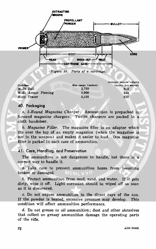
PRIECTID A
Figure 56. Parts of a cartridge.
Average muile velodcityCartdride Mra rnM e (meseg ) (meters per ae¢nd)M-59 Ball 3,750 853M-61 Armor Piercing 2,900 844M-62 Tracer 3,100 838
40. Packaginga. 5-Round Magazine Charger. Ammunition is prepacked in
5-round magazine chargers. Twelve chargers are packed in acloth bandoleer.
b. Magazine Filler. The magazine filler is an adapter whichfits over the top of an empty magazine (when the magazine isnot in the weapon) and makes it easier to load. One magazinefiller is packed in each case of ammunition.
41. Care, Handling, and PreservationThe ammunition is not dangerous to handle, but there is a
correct way to handle it.a. Take care to prevent ammunition boxes from becoming
broken or damaged.b. Protect ammunition from mud, sand; and water. If it gets
dirty, wipe it off. Light corrosion should be wiped off as soonas it is discovered.
c. Do not expose ammunition to the direct rays of the sun.If the powder is heated, excessive pressure may develop. Thiscondition will affect ammunition performance.
d. Do not grease or oil ammunition; dust and other abrasivesthat collect on greasy ammunition damage the operating partsof the rifle.
72 AGO 27i6B
42. StorageSmall arms ammunition is not an explosive hazard, but under
poor storage conditions it may become a fire hazard. It shouldbe stored away from radiators, hot water pipes, and other sourcesof heat.
AGO 2766B 73
APPENDIXREFERENCES
AR 320-5 Dictionary of United States Army Terms.AR 320-50 Authorized Abbreviations and Brevity Codes.FM 21-5 Military Training.FM 21-6 Techniques of Military Instruction.FM 21-30 Military Symbols.FM 21-40 Small Unit Procedures in Atomic, Biological,
and Chemical Warfare.FM 23-5 U.S. Rifle, Caliber .30, M1.FM 23-71 Rifle Marksmanship Course, TRAINFIRE I.DA Pam 108-1 Index of Army Motion Pictures, Film Strips,
Slides, and Phono-Recordings.
74 AGO 2766B
[AG 474.2 (22 Oct 59)]
By Order of Wilber M. Brucker, Secretary of the Army:
L. L. LEMNITZER,General, United States Army,
Official: Chief of Staff.R. V. LEE, ..
Major General, United States Army,The Adjutant General.
Distribution:Active Army:
Tech Stf, DA (1) Sig Bn (3)Tech Stf Bd (2) Armor Bn (3)USCONARC (25) ADA Bn (3)USA Arty Bd (2) MP Bn (3)USA Armor Bd (2) Inf Co (5)USA Inf Bd (2) Armor Co (3)USA AD Bd (2) Cml Co (3)USA Abn & Elet Bd (2) Ord Co (3)USA Avn Bd (2) QM Co (3)USATB (2) MP Co (3)US ARADCOM USMA (30)
(Incl ea Rgn) (2) PMST Sr Div Unit (2)OS Maj Comd (10) PMST Jr Div Unit (2)OS Base Comd (5) PMST Mil Sch Div Unit (2)Log Comd (5) Mil Msn (1)MDW (5) USATC (10) exceptArmies (10) except USATC (Inf) (25)
First US Army (12) Svc Colleges (5)Corps (5) Br Svc Sch (5) exceptDiv (8) (ea CC) (3) USAIS (1000)Bde (3) USAAMS (1200)Engr Gp (3) USAES (10)Inf Bg (5) USA Ord Sch (50)Arty Gp (3) USASCS (49)Cml Bn (3) Mil Dist (1)Engr Bn (5) Sector Comd (Res) (1)Arty Bn (3) USA Corps (Res) (1)Ord Bn (3) Units org under fol TOE:QM Bn (3) 17-52 (3)
NG: State AG (3); units-none.USAR: Units-same as Active Army except allowance is two (2) copies
to each unit.For explanation of abbreviations used, see AR 320-50.
AGO 2766B 75
* U. S GOVERNMENT PRINTING OFFICE: 1960 0-s55518


![AD-A022 357__Evaluation of 7.62 MM Cartridges Assembled With Caliber .30 API and Incendiary Bullets [1975]](https://img.pdfslide.us/doc/110x75/577cdb2f1a28ab9e78a78e6a/ad-a022-357evaluation-of-762-mm-cartridges-assembled-with-caliber-30-api.jpg)