Embed Size (px)
Citation preview
Issued 20120229 1
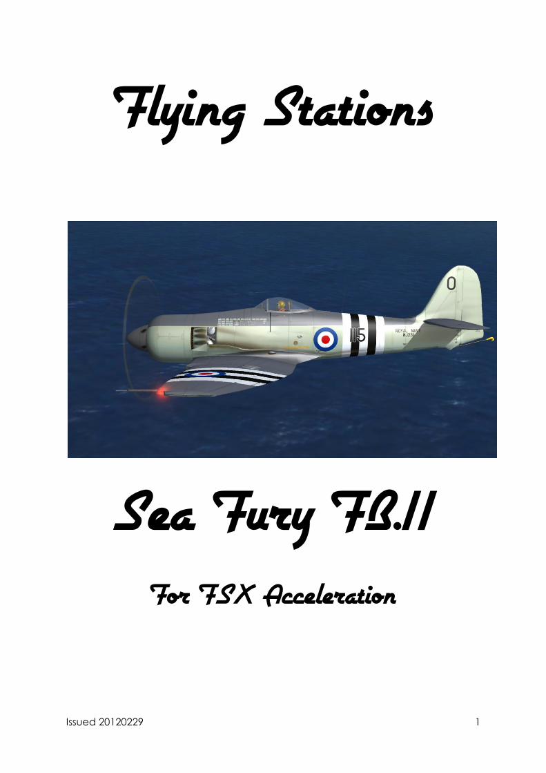
Flying Stations
Sea Fury FB.11 For FSX Acceleration
Issued 20120229 2
Introduction
The Hawker Sea Fury was the ultimate development of the Typhoon/Tempest line of
fighters that saw use in the latter half of the Second World War. Although originally
designed against the dual requirements of Air Ministry specification F.2/43 and
Admiralty specification N.7/43 the end of hostilities saw the RAF’s order cancelled
leaving only the Bristol Centaurus XVIII powered Naval variant to enter production.
Two variants were produced, the F.10 and the FB.11, the range F.1-9 being reserved
for potential air force versions that were never produced. The only difference
between the two was the ability of the FB.11 to carry a bomb under each wing.
With 2,480 HP available from the 18 cylinder radial engine the Sea Fury was one of
the fastest piston powered aircraft produced and was able to hold her own against
the early jets, notably in Korea where at least one MiG-15 fell to her 20mm cannons.
Entering squadron service with the Fleet Air Arm in 1947 the Sea Fury served with 9
front line squadrons as well as numerous second line units. Additionally the aircraft
served with the navies of Australia, Canada and the Netherlands as well as the air
forces of Iraq, Pakistan, Egypt, Burma and Cuba. Air force versions were a mixture of
former RN examples de-navalised and purpose built examples which notably lacked
the upsweep at the base of the rudder to accommodate the tail hook. To allow re-
painters to represent air force de-navalised Furies the tail hook only appears on
aircraft with the word ‘Sea’ in the Title = section of the aircraft.cfg file.
Issued 20120229 3
Installation Notes
To accommodate various extra functions in the aircraft on first loading you will be
asked if you want to allow the Centaurus.dll gauge to operate. Additionally the
following extra control has been added:
Weapons Release - Ctrl+Shift+m or Joystick Button 0 (trigger)
Aircraft Configuration
Once the aircraft is loaded it is possible to set the desired fuel and weapon load via
the loading sheet (Shift+1). It is necessary for the parking brake to be applied for the
load to be successful. Note, the loading sheet fuel total refers to internal fuel only,
hence without the drop tanks selected FSX will indicate approximately 68% fuel load.
Aircraft Systems
Fuel System
The Sea Fury’s fuel system comprises 4 internal tanks and two optional drop tanks.
The internal tanks comprise a 127 Imperial Gallon main tank aft of the firewall, a 28
Imp Gal inter-spar tank in each wing and a 17 Imp Gal nose tank in the starboard
wing (replaced by the oil cooler in the port wing). Fuel from the wing tanks is
transferred automatically to the main tank via air pressure from the exhaust side of
the engine’s vacuum pump.
If drop tanks are fitted a selector lever (42) on the cockpit starboard shelf allows the
pilot to transfer fuel from the drop tanks in the forward position or the wing tanks in
the aft position. Note if drop tanks are not fitted and the lever is in the forward
position the wing fuel will not be transferred to the main tank.
Contents gauges for the internal tanks (47, 48, 49) are located on the cockpit
starboard shelf, together with a low fuel warning light (41) that illuminates when the
main tank level falls below 107 Imp Gal.
A fuel tanks air pressure gauge (39) is also located on the starboard cockpit shelf, in
normal operation it should indicate between 3 ¼ and 5 lb/sq. in, if the pressure falls
below 3 ¼ ib/sq. in fuel may not transfer satisfactorily at altitude.
Issued 20120229 4
Flying Controls
The flying controls consist of direct controls for the rudder and elevator and servo
tabs for the ailerons. Consequently trim is only available in pitch and yaw, the hand
wheels (1, 5) for which are located on the cockpit port shelf with the indicator unit
(2) positioned between them. Note, the servo tabs operating the ailerons require a
flow of air over them to actuate the control surface, consequently when the aircraft
is stationary on the ground only servo tab movement will occur when the controls
are moved.
Engine Controls
The engine controls allow single lever operation of the engine as well as preventing
over boosting of the engine.
The two speed supercharger allows +9.5 lb/sq. in boost to be maintained to 4000’ in
‘M’ gear and 16000’ in ‘S’ gear. Note due to the reduced heating of the charge air
in ‘M’ gear there is around 500hp more power at sea level and there is no
advantage to using ‘S’ gear until around 7500’. The supercharger lever (7) allows for
selection of the ‘M’ and ‘S’ gearing, if the ‘S’ gearing is selected below 7000’ a
warning lamp will illuminate on the front panel.
The throttle lever (11) is linked to the engine via a barometric unit that prevents the
butterfly valve opening beyond +9.5 lb/sq. in of boost, consequently the pilot is not
required to monitor the boost level while moving the throttle.
The R.P.M. control lever (10) allows setting of the engine R.P.M. via the propeller
constant speed unit in the usual manner, additionally by moving it fully aft (within the
final 5% of movement in FSX) the system enters automatic mode and will set the
R.P.M. as appropriate for the current boost setting. Thus the automatic mode
relieves the pilot of the requirement to set the R.P.M. while changing throttle settings.
Mixture control is fully automatic and the control (8) only needs to be touched to cut
the fuel supply for engine shut down.
The cooling flaps are operated by a spring loaded switch (29) on the front console,
left clicking moves the switch to the open position, right clicking to the close position.
The switch will return to the off position on release or reaching the fully open/closed
position. In general operation it is sufficient to fully open or close the flaps as
required hence no indicator is provided.
Issued 20120229 5
Radio and Autopilot
The original production Sea Furies were fitted with a four channel VHF transceiver,
this allowed for one of four pre-tuned frequencies to be selected, no manual tuning
was possible. They were subsequently upgraded with 10 and then 40 channel units.
Due to the incompatibility of such systems with the FSX ATC network a pop-up radio
panel is included featuring a communication radio and transponder. Although the
real aircraft was not fitted with one a basic autopilot is also included to ease pilot
workload on long range transits. The radio sub-panel is accessed via Shift+2.
Additionally a GPS is accessible via Shift+3
Armaments
As modelled the FB.11 is capable of carrying either two 500lb bombs or 2-6 60lb
rockets. Once loaded via the armament panel they can be selected for launch via
the armament switch (6), left clicking to move aft, right clicking to move forwards.
Once a selected the stores may be fired via the trigger button on the joystick, or the
Ctrl+Shift+m key combination. Note as the trigger is typically mapped to the aircraft
brakes as well it is unwise to make the armament switch prior to take-off.
RATOG
Rocket Assisted Take-Off Gear can be loaded via the Loading Panel. Rocket burn is
~4 seconds giving a ~45kt speed boost.
To operate, ensure the Armament Selector (6) is set to safe and the RATOG Master
Switch (9) is on (Up), this will make the trigger live. Commence the take-off run as
normal to ensure the aircraft is running true, operate the trigger to initiate the RATOG
burn, apply slight left aileron and lift the aircraft off the ground once flying speed has
been achieved ~100kts.
Once the aircraft is safely airborne and cleaned up the RATOG can be jettisoned
via the pushbutton (4).
Identification Lights
Three under wing identification lights are fitted, the Red and Green ones under the
starboard wing and the Amber under the port wing. To select the desired colour use
switch (51) left clicking to move it aft, right clicking to move it forwards. The
OFF/MORSE/STEADY switch (50) allows the selected light to either be used as a Morse
signalling lamp via the Morse key (52) or a continuously illuminated light. Again left
clicking will move the switch aft, right clicking forwards.
Issued 20120229 6
Handling
Engine start and warm up
Prior to start confirm:
Ignition Switches (18) OFF
Main Fuel Cock (40) ON
Fuel Cut-Off (8) RICH
Throttle (11) ½” Open
R.P.M. Control (10) MAXIMUM
Engine Cooling Shutters (29) OPEN
Supercharger Control (7) M
Note the static boost reading (usually 0 lb/sq. in under standard atmosphere
conditions at sea level) (31).
Prime the injectors with the pushbutton (44).
Prime the cylinders with the pushbutton (45).
Index the starter breech (16) and switch ON the ignition (18).
Press the starter pushbutton (46), the starter cartridge will accelerate the engine to
~500 R.P.M. almost instantaneously.
If a cartridge fires but fails to start the engine, repeat the above procedure, ensuring
the engine is re-primed.
Run the engine at 1200 R.P.M. and warm up at this speed.
Exercising and Testing
Warm up to ~120ºC C.H.T. and >15ºC Oil Temperature.
Test each magneto before increasing power further.
Holding the control column well back increase the throttle until the static boost
reading is obtained, check the generator failure lamp is out.
Issued 20120229 7
At the same boost, check the operation of the constant speed propeller by moving
the control lever over its full range at least twice (note moving the lever below 5%
will activate the automatic control unit and is not necessary for the test) then return
to maximum.
At the same boost exercise the supercharger by changing to high gear, R.P.M.
should drop by ~150. After around 30 seconds change back to low gear and
confirm the R.P.M. rises.
At the same boost test each magneto in turn; single ignition drop should not exceed
50 R.P.M.
Take Off
Trimming Tabs:
Elevator Neutral (without flap)
½ Div nose up (with flap)
R.P.M. Lever Max R.P.M. position
Fuel Check contents
Flaps Up (airfield)
Max lift (catapult)
Take-off (carrier)
Wings Spread and locked
Engine cooling shutters Open
Supercharger ‘M’ (low gear)
Canopy Open
Tail wheel Locked
Full throttle should always be used for take-off, although the aircraft may become
airborne before the full throttle position is reached. Note due to the large amount of
torque generated by the Centaurus engine it is inadvisable to rapidly open the
throttle.
The tendency to swing to the right can be controlled easily by the rudder particularly
if the aircraft is flown off tail down.
When taking off with flap deployed the aircraft should be flown off tail down.
Issued 20120229 8
When comfortably airborne move the R.P.M. control lever smoothly back to AUTO
before reducing boost.
Climbing
Maximum rate of climb speed is 165 knots from sea level to 20000’, thereafter
decreasing by 5 knots per 4000’ increase in altitude. There is little loss in rate of
climb, and the handling is better, if the climbing speed is increased to 185 knots.
For economical climbing, place the R.P.M. lever in AUTO, set the throttle to give no
more than 2250 R.P.M. and climb at 165 knots, reducing as appropriate above
20000’.
General Flying
Changes of Trim
Gear Down Slightly Nose Down
Gear Up Nose Up
Flaps Down Nose Down
Flaps Up Nose Up
Engine Cooling Shutters Open Nose Down
Engine Cooling Shutters Closed Nose Up
Due to the torque from the engine there is a change in directional trim with
alterations is speed and power.
Flying at reduced airspeed should be done with opening the canopy below 170
knots, and lowering the flaps to MAX LIFT. Set the R.P.M. control to give 2200 R.P.M.
and fly at about 145 knots.
Stalling, the approximate stall speeds, engine off, cooling shutters closed in knots
are:
12400lb 14650lb
Flaps and gear up 105 115
Flaps and gear down 90 100
Power on,
Issued 20120229 9
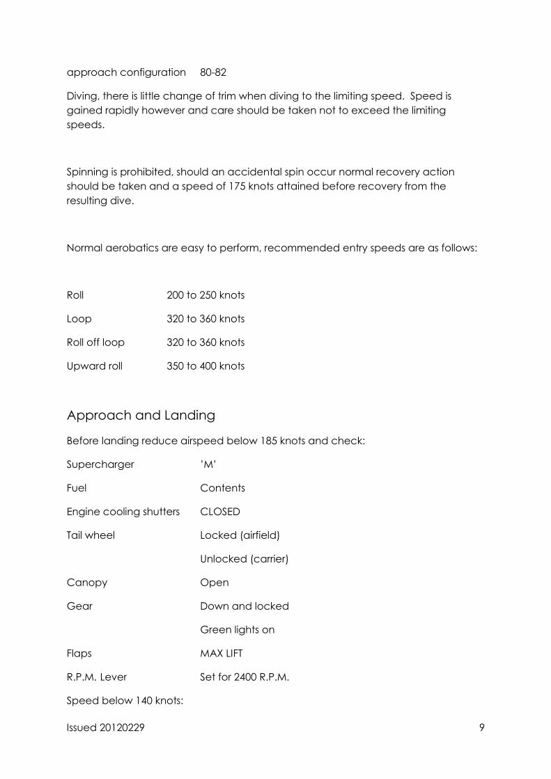
approach configuration 80-82
Diving, there is little change of trim when diving to the limiting speed. Speed is
gained rapidly however and care should be taken not to exceed the limiting
speeds.
Spinning is prohibited, should an accidental spin occur normal recovery action
should be taken and a speed of 175 knots attained before recovery from the
resulting dive.
Normal aerobatics are easy to perform, recommended entry speeds are as follows:
Roll 200 to 250 knots
Loop 320 to 360 knots
Roll off loop 320 to 360 knots
Upward roll 350 to 400 knots
Approach and Landing
Before landing reduce airspeed below 185 knots and check:
Supercharger ’M’
Fuel Contents
Engine cooling shutters CLOSED
Tail wheel Locked (airfield)
Unlocked (carrier)
Canopy Open
Gear Down and locked
Green lights on
Flaps MAX LIFT
R.P.M. Lever Set for 2400 R.P.M.
Speed below 140 knots:
Issued 20120229 10
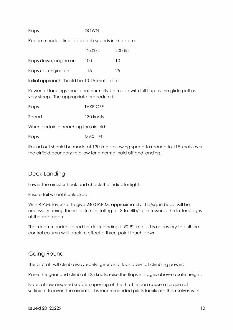
Flaps DOWN
Recommended final approach speeds in knots are:
12400lb 14000lb
Flaps down, engine on 100 110
Flaps up, engine on 115 125
Initial approach should be 10-15 knots faster.
Power off landings should not normally be made with full flap as the glide path is
very steep. The appropriate procedure is:
Flaps TAKE OFF
Speed 130 knots
When certain of reaching the airfield:
Flaps MAX LIFT
Round out should be made at 130 knots allowing speed to reduce to 115 knots over
the airfield boundary to allow for a normal hold off and landing.
Deck Landing
Lower the arrestor hook and check the indicator light.
Ensure tail wheel is unlocked.
With R.P.M. lever set to give 2400 R.P.M. approximately -1lb/sq. in boost will be
necessary during the initial turn in, falling to -3 to -4lb/sq. in towards the latter stages
of the approach.
The recommended speed for deck landing is 90-92 knots, it is necessary to pull the
control column well back to effect a three-point touch down.
Going Round
The aircraft will climb away easily, gear and flaps down at climbing power.
Raise the gear and climb at 125 knots, raise the flaps in stages above a safe height.
Note, at low airspeed sudden opening of the throttle can cause a torque roll
sufficient to invert the aircraft. It is recommended pilots familiarise themselves with
Issued 20120229 11
this phenomena at altitude at the earliest opportunity to enable them to anticipate
and counteract it.
Running Down and Stopping the Engine
The engine should be idled at 800 – 1000 R.P.M. and the magnetos checked for a
dead cut.
Stop the engine by closing the throttle and setting the fuel cut off to CUT-OFF.
Ignition Switches OFF
Fuel Cock OFF
Electrical Services OFF
Ground/Flight Switch GROUND
Issued 20120229 12
ILLUSTRATIONS
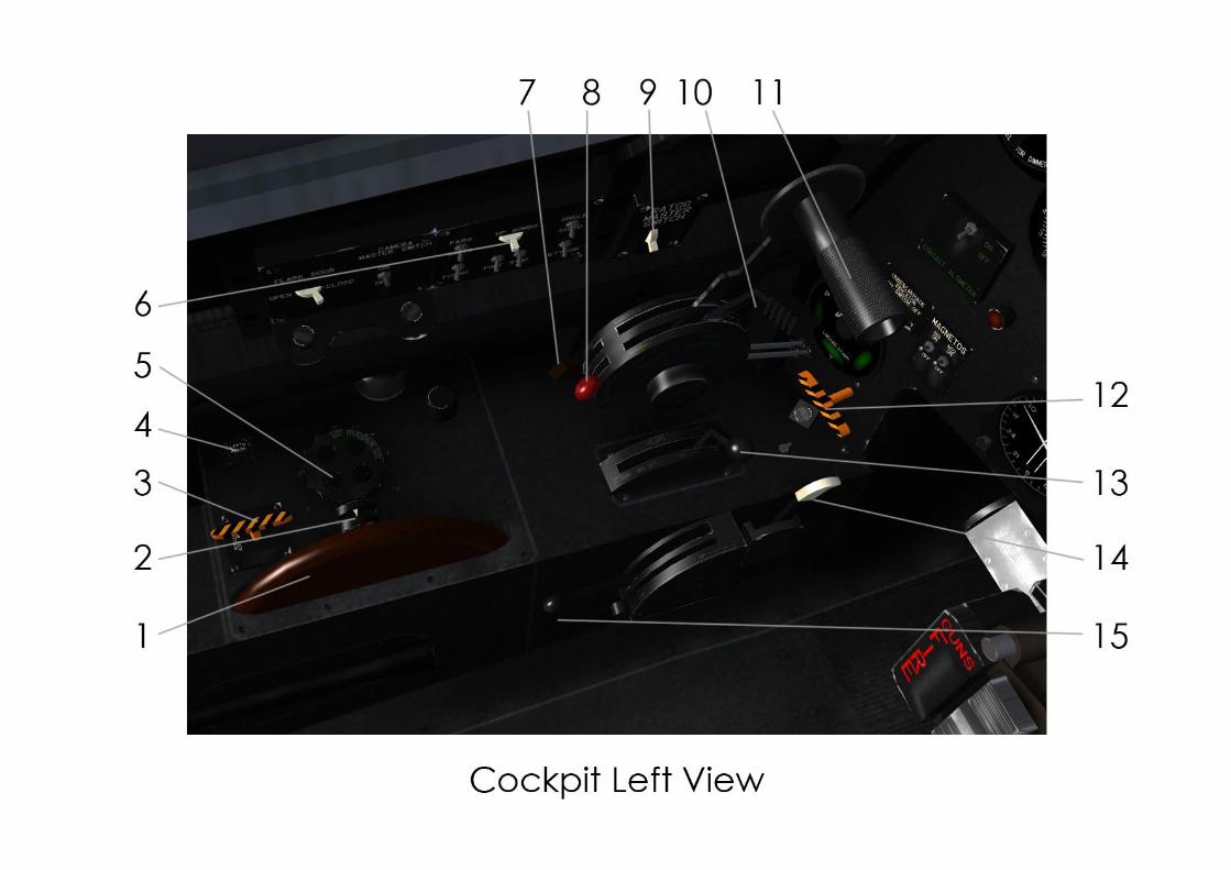
1. Cockpit Left View
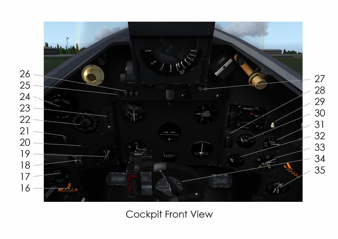
2. Cockpit Front View
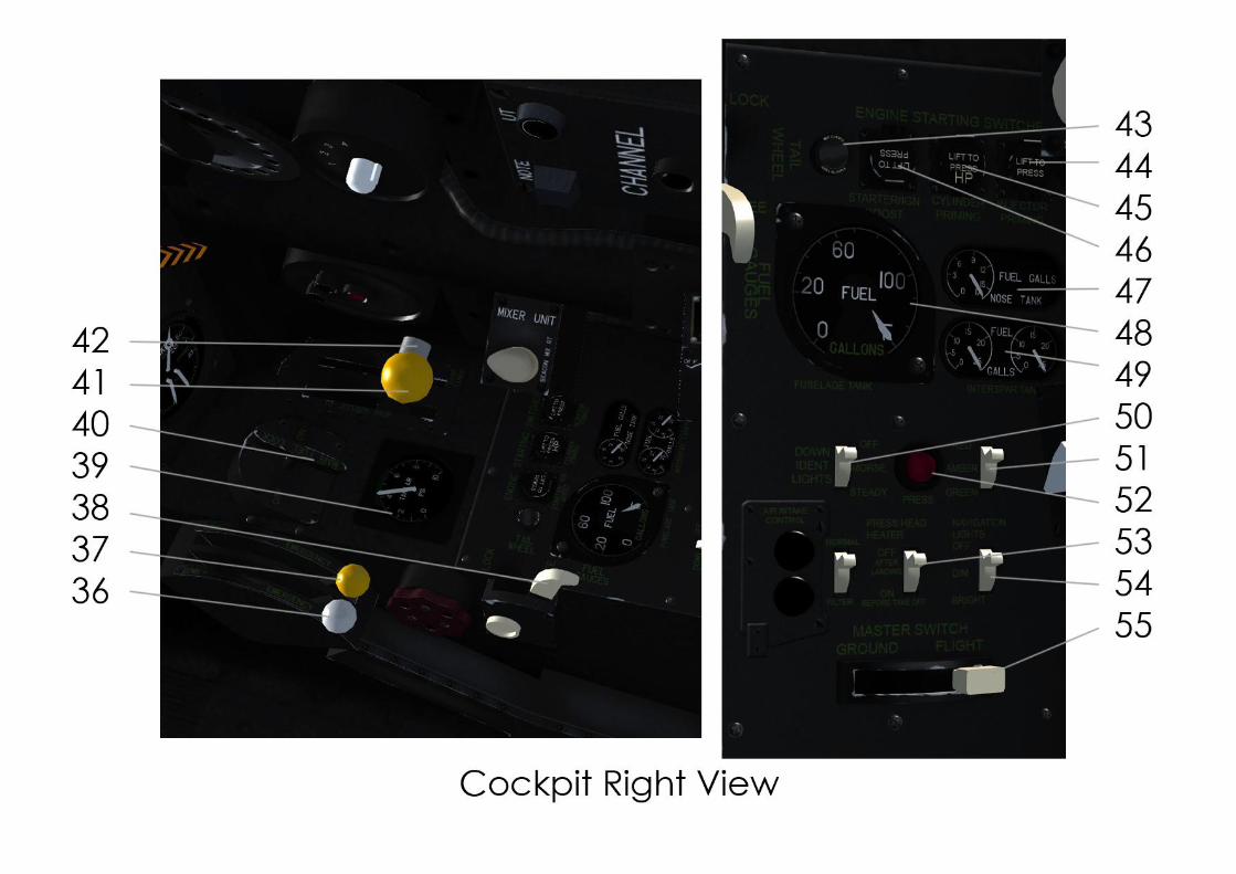
3. Cockpit Right View and Sub-Panel Inset
Key to Illustrations
1 Elevator trim wheel
2 Trim indicators
3 Stores jettison
4 RATOG Jettison
5 Rudder trim wheel
6 R.P. Bombs Selector Switch
7 Supercharger gear change lever
8 Fuel cut-off control
9 RATOG Master switch
10 R.P.M. lever
11 Throttle lever
12 Tail hook indicator lamp
13 Flap lever
14 Tail hook lever
15 Gear lever
16 Starter re-indexing control
17 Gear indicator
18 Magneto switches
19 R.I. compass indicator
20 Supercharger warning light
21 Contacting altimeter switch
22 Contacting altimeter
23 Flap indicator
24 Gyro gun sight dimmer
25 Gear warning light
26 Gyro gun sight master switch
27 Cockpit lighting switch
28 Oil pressure gauge
29 Cooling flaps switch
30 Oil temperature gauge
Issued 20120229 13
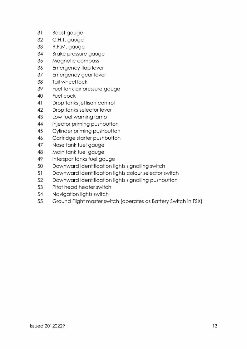
31 Boost gauge
32 C.H.T. gauge
33 R.P.M. gauge
34 Brake pressure gauge
35 Magnetic compass
36 Emergency flap lever
37 Emergency gear lever
38 Tail wheel lock
39 Fuel tank air pressure gauge
40 Fuel cock
41 Drop tanks jettison control
42 Drop tanks selector lever
43 Low fuel warning lamp
44 Injector priming pushbutton
45 Cylinder priming pushbutton
46 Cartridge starter pushbutton
47 Nose tank fuel gauge
48 Main tank fuel gauge
49 Interspar tanks fuel gauge
50 Downward identification lights signalling switch
51 Downward identification lights colour selector switch
52 Downward identification lights signalling pushbutton
53 Pitot head heater switch
54 Navigation lights switch
55 Ground Flight master switch (operates as Battery Switch in FSX)
Issued 20120229 14
jhjhhkjhkjhkh
Issued 20120229 15
Issued 20120229 16

Issued 20120229 17
Credits/Blame
Philip J Chandler - 3D Model, Gauge Programming, Flight Model
Fraser M Paterson - Textures, Testing
Rich Ruscoe - Flight Model,
Steve Beeny - Web Guru
Feedback is appreciated via our web forums http://z13.invisionfree.com/Flying_Stations/.