Embed Size (px)
Citation preview

AFFDL-TR-79-3 126 ~L V LS~L[VEL5
00
FLYING QUALITIES DESIGN REQUIREMENTSFOR SIDESTICK CONTROLLERS
G. THOMAS BLACKDA VID J. MOORHOUSE
CONTROL D YNAMICS BRANCHFLIGHT CONTROL DIVISION
DTICOCTOBER 1979 J 5 1980
BTECHNICAL REPORT AFFDL-TR-79 3126Final Report for period October 1978 - August 1979
Approved for public release; distribution unlimited.
AIR FOF.CE FLIGHT DV NAMICS LABORATORYAIR FORCE WRIGHT AERONAUTICAL LABORATORIESAIR FORCE SYSTEMS COMMANDL W.1 WRIGHT.PATTERSON AIR FORCE BASE, OHIO 45480; -J$&a
NOTICE
When Government drawings, specifications, or other data are used forany purpose other than in connection with a definitely related Governmentprocurement operation, the United States Government thereby incurs no respon-sibility nor any obligation whatsoever; and the fact that the government mayhave formulated, furnished, or in any way supplied the said drawings, speci-fications, or other data, is not to be regarded by implication or otherwiseas in any manner licensing the holder or any other person or corporation, orconveying any rights or permission to manufacture, use, or sell any patentedinvention that may in any way be related thereto.
"This report has been reviewed by the Information Office (0') and isreleasable to the National Technical Information Service (NTIS). At NTIS,it will be available to the general public, including foreign nations.
Thi ech c report has been reviewed and is approved for publication.
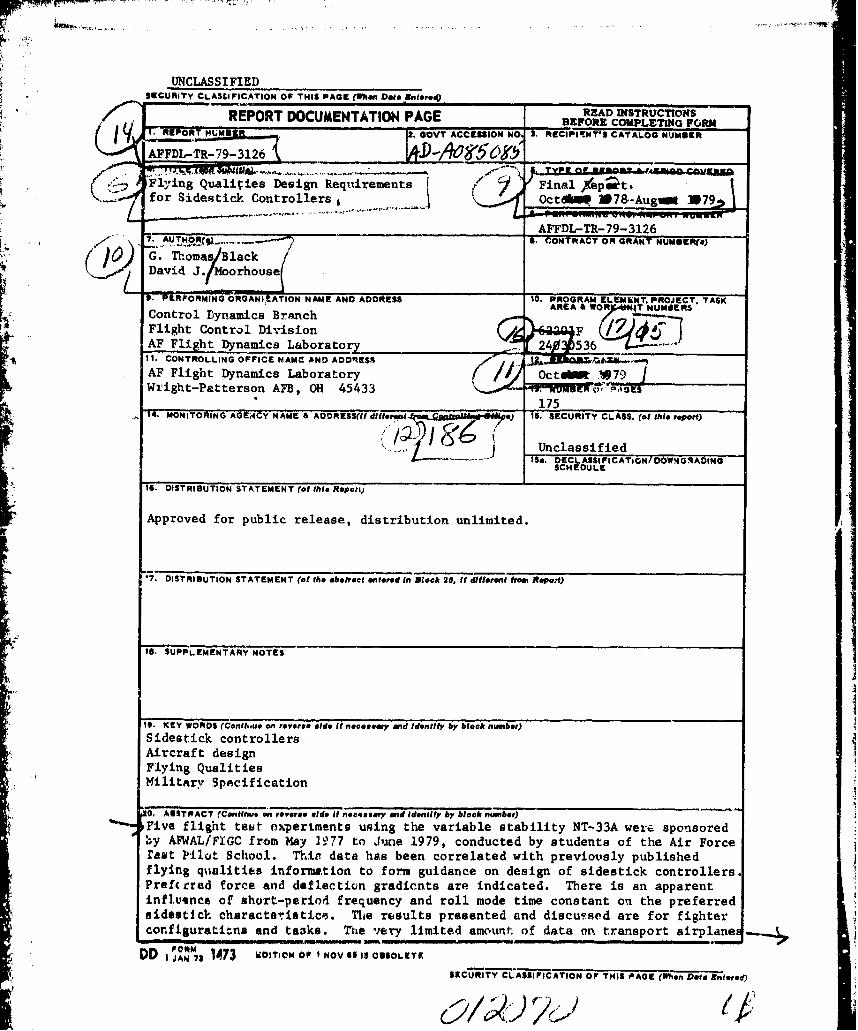
G. T omas Black, Project Engineer V. 0. Hoehne, Acting ChiefControl Dynamics Branch Control Dynamics BranchFlight Control Division Flight Control Division
David J. . piohouse, Project Engineer
Control D amics BranchFlight Control Division
FOR THE COMMANDER
SI/x
Morris A. Ostgdard, Acting 'ChiefFlight Control Division
"If your address has 'hanged, if you wish to be removed from our mailing
list, or if the addressee is no longer employed by your organization pieasenotify AFWA.L/FIGC,WPAFB, OH 45433 to help us maintain a current mailing list."
Copies of this report should not be returned unless return is required bysecurity conaiderations, contractual obligations, or notice on a specificdocuntet.. *
OIiR VORC'i/IS67O/5 May 190 -- 420
!"A
UNCLASSIFIEDSE9CURiTY CLASSIFICATION OF THIS PACE Whuen DateA BteroiQ__________________
READ INSTRUCTIONSREPORT DOCUMENTATION PAGE BEFORE COMPLETING FORM
Flying Qualities Design Reqtuirementsfor Sidestick, Controllers6Otk 9&Agi 17
Gý. T~masBlack
Control Dynamics Branch 0Flight Control Division
Wtight-Petterson AFB, OH 45433 ME
IT MNITRIN AGACYNAM& ADRES(Itdifor" QmkPUha*i.@iU/e) 15. SECURITY CLASS. (of this report)
Unclassified15a. DECL ASSI FICATIOaN/ DOWN4 GRADING
SCH EDULE
IS. DISTRO1bUTION STATEMENT (of this Repati)
Approved for public release, distribution unlimited.iw
47. DISTRIBUTION STATEMENT (of the abstract entered tn Block 20, it different from Reopo't)
IS. SUPPLEMENTARY NOTES
I9. KEY WORDS (Conthm~e on rovere@ side If necessary and Identify by block number)Sideatick controllersAircraft designFlying QualitiesMilitary Specification
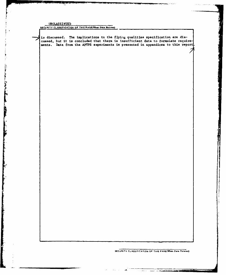
0. ANST PACT rcenttnus an reverse. #Ode it necessary aid identify by block number)Five fli&nt test ox-pertments using the variable stability NT-33A were sponsored,;y AFWAL/FIGC from May 11,77 to June 1979, conducted by students of the Air Forcerest Pilot School. ThitI data has been correlated with previously publishedflying qusalities information to form guidance on design of sidestick controllers.Prefcrred force and deflection gradients are indicated. There is an apparentinflutnce of short-period frequency and roll mode time constant on. the preferredsidsetick cheracte-risticoD. Tits results presented and discu-Faed are for fightercornfiguratimna nd tazka. 7he very limited amount. of data or'. transport airplanes
DD I JAN7 1473 wDITO FINV SSOSLT
SECURITY CLASSIFICATION OF THIS PAGE meDtantrd
UNCLASSIFIEDSECURITY CLASSIFICATION OF THIS PAGI(1WTh Data Kniceed) _.,,_•_-_
is discussed. The implications to the flyi~ig qualities specification are dis-cussed, but it is concluded that there is insufficient data to formulate require-ments. Data from the AFTPS experiments is presented in appendices to this report
rI
SECURITY CLASSIFICATION OF THIS PAGE('Whein Date J'ntered)
FOREWORD
This report was prepared by Mr. Black and Mr. Moorhouse of the
Flying Qualities Group, Control Dynamics Branch, Flight Control Division.
The effort was conducted under Program Element 62201F, Project 2403,
Task 05, Work Unit 36. This is the final report for the time period
October 1978 through August 1979.
The conclusions presented herein are based partly on previously
unpublished work conducted by students of the Air Force Test Pilot School.
Five flight test experiments using the variable stability NT-33A were
sponsored by AFFDL/FGC from May 1977 to Jun, e 1979. Technical results of
these tests, extracted from the project reports, are presented in
Appendices B-E. The data collected is the result of contributions by
large number of people: the students of the AF Test Pilot School who
conducted the experiments, listed by name in the data appendices;
Major John Hoffman, Major George Muellner and Major Jim Tilley, AFTPS
faculty advisors to the projects; and Stephen Smith and Lt David Maunder,
AFFTC program managerE. Each of the project reports additionally cited
the considerable assistance received from the Calspan Corporation safety
pilots and support personnel.
ACIMESION forNTIS White Section
DDC Buff Section 0UNANNOUNCED "1JUSTFIICATION
BY
DISTRIBUTION/AVAILABILITY COEDist. AVAiL, and/or SPFCIAL
•: iii

TABLE OF CONTENTS
Section
I INTRODUCTION 1
II HISTORY 3
III DATA AVAILABILITY 6
IV DATA CORRELATION AND ANALYSIS 10
A. Evaluation Tasks Used 10
B. Sidestick Deflection Geometry, Locationand Control Switches 12
C. Longitudinal Deflection/Force and Force/Response Characteristics 15
D. Effects of Short-Period Dynamics 22E. Roll Deflection/Force Gradients,
Response, and Control Harmony 25
F. Trim Systems 29
G. Use of Prefilters 31
V DESIGN GUIDANCE 32
VI IMPLICATIONS TO THE FLYING QUALITIESSPECIFICATION 36
A. Force and Deflection Limits 34B. Pitch Response Characteristics 34
C. Roll Response Characteristics 35
VII CONCLUSIONS AND RECOMMENDATIONS 37
APPENDICES
A A SAMPLE DESIGN PROBLEM 39
B TECHNICAL RESULTS AND D!SCUSSION FROM USAF TESTPILOT SCHOOL LETTER REPORT - 1 July 1977 43
C TECHNICAL RESULTS AND DISCUSSION FROM USAF TESTPILOT SCHOOL LETTER REPORT - 9 December 1977 80
D TECHNICAL RESULTS AND DISCUSSION FROM USAF TESTPILOT SCHOOL LETTER REPORT - 5 July 1978 105
E TECHNICAL RESULTS AND DISCUSSION FROM USAF TESTPILOT SCHOOL LETTER REPORT - 6 December 1978 131
F TECHNICAL RESULTS AND DISCUSSION FROM USAF TESTPILOT SCHOOL LETTER REPORT - 5 June 1979 156
REFERENCES 172
ADDITIONAL BIBLIOGRAPHY 175
v
ILLUSTRATIO, S
C o i~re Page
1. Some F-1041 SSCS Evaluition Tasks 11
2. A Comparison of T% Pitcl, and Roll P-vot Location Sets 14
3. Test Matrix from Referer.ces 2, 3 and 4 18
4. Longitudialaa Force/Response Gradie',ts from References2, 3 and 4 18
5. Summary af Pilot Ratings from References 2, 3 and 4 19
6. Longitudinal Force/Deflection and force/ResponseGradierts from Refer;nce 1 20
7. Summary of Results from References 1 - 4 21
8. Longitudinal Response vs Normalized ForcEi:DefloctionGradients 23
9. Short-Period FrequencY vs Longitudiral Force/ResponseGzadient 26
10. Lateral Configurationn Evaluated in Refs 2 and Z 27
i1. Lateral Configuratl.n-i Evaluated in Referencs 1 27
12. Summary of Lateral Pilot Rating' 28Preierred Conto.-llacmony 30
14. i're"ferred Pitc.,.i Response/Force Gradleut 40
15. Preferred Roll Response/Forne (radient 42
16. Control Forec/Resvonse 0aitts, Flight PhaaeCategory A 47
17. Control Force/Response Gains, Flight PhaseCategory C 48
18. Control Coniiguration for Category A Tasks 49
19. Control Configuration for Category C Tasks 49
20. Dive Bomb Pattern 51
21. Areas of Control Configuration Relative Performance 54
22. Pilot Comments for Air-to-Air Tasks with StandardHarmony 55
23. Pilot Ratings with Standard Control Harmony 56
24. Average Pilot Ratings with Standard Control Harmony 57
25. Individual Averages of Pilot Ratings with StandardControl Harmony 58
26. Averages of Individual Pilot Rating Averages withStandard Control Harmony 59
vi
ILLUSTRATIONS (Continued)
2V. Median of Individual Pilot Averages with StandardControl Harmony 60
28. Medians of Pilot Ratings with Standard C.-ntrolHarmony 61
29. Iniividual Medians of Pilot Ratiugs with StandardControl Harmony 62
30. Average of Individual Median Pilot Ratings withStandard Control Harmony 63
31. Tnadian of Individual Median Pilot Ratings withStandard Control Harmony 64
32ý Pilot Ratiag Standard Deviations with Standard ControlHarmony 65
33. Pilot Ratings for Air-to-Air Tracking with One PoundBreakout Force 66
34. Pilot Comments for Air-to-Air Tracking with One PoundBreakout Force 68
35. Pilot Ratings for Air-to-Air Tasks with Lighter LateralForce Gradients 69
36. Pilot Comments for Air-to-Air Tasks with Lighter LateralForce Gradients 70
37. Pilot Ratirgs for Air-to-Air Tasks with Heavier LateralForce Gradients 71
38. Pilot Comments for Air-to-Air Tasks with Heavier LateralForce Gradients 72
39. ATAGAS Plots of Pipper Motion (Configuration 10) 73
40. ATAGAS Plots of Pipper Motion (Configuration 7) 74
41. ATAGAS Plots of Pipper Motion (Configuratiou 13) 75
42. Pilot Ratings for Air-to-Ground Tracking Tasks withStandard Control Harmony 76
43. Pilot Ratings for Approach Task 77
44. Pilot Ratings for Landing Tasks 77
45. Typical Pilot Comments for the Approach and LandingTasks 78
46. Test Configurations 8247. Control Configurations 86
4e. Overall Cooper-Harper Ratings (Raw Data) 89
vii
-!
ILLUSTRATIONS (Continued)
Figure Page
49. Pilot Comments 90
50. Formation and Air-to-Air Tracking Results 98
51. Landing Task Results 99
52. Pilot Background Information 103
53. Cooper-Harper vu uc - Gross Acquisition 110
54. Cooper-Harper vs wc - Gross Acquisition 110
55. Cooper-Harper vs wc - Fine Tracking 111
56. Cooper-Harper vs wc - Fine Tracking 111
57. Cooper-Harper ve wc - Landing 112
58. Cooper-Harper vs wc - Lending 112
59. Pilot Comments 113
60. Preference Rating vs wc - Gross Acquisition 118
61. Preference Rating vs w - Gross Acquisition 11862. Preference Rating vs •c - Fine Tracking 119
62. Preference Rating vs wc - Fine Tracking 119
64. Preference Rating vs wc - Landing 120
65. Preference Rating vs w(c - Landing 120
66. Tracking Errors in Lazy Eight Maneuvers 122
67. Tracking Errors in Constant-a and Wind-up TurnManeuvers 123
68. Pilot Background Information 125
69. Tracking Results 128
70. Tracking Results 129
71. Sidestick Force Response Characteristics - Air-to-AirTracking 134
72. Air-to.*Air Test Configurations 1.35
73. Condensed Pilot Comments 138
74. Baseline Configiuration Strip Chart Records, Pilot C,Maneuver #3 (withiout oscillations) 147
75. Baseline Configuiation Strip Chart Records, Pilot C,Maneuver #3 (with os,.Aillations) 148
76. Short Period Dynatics (alibrations, Air-to-Air Tracking 150
77. Dutch Roll and Ro1l Mode Time Constant D,.namicsCalibrations, Air-to-Air Tracking 151
78. Lateral Force-Respoise Gradients 160
viii 4
~~~~~~~~~~~j. ... . ... .0''1'.m • + + • + • rl ' i i i
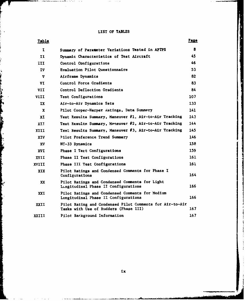
LIST OF TABLES
Table .fPa
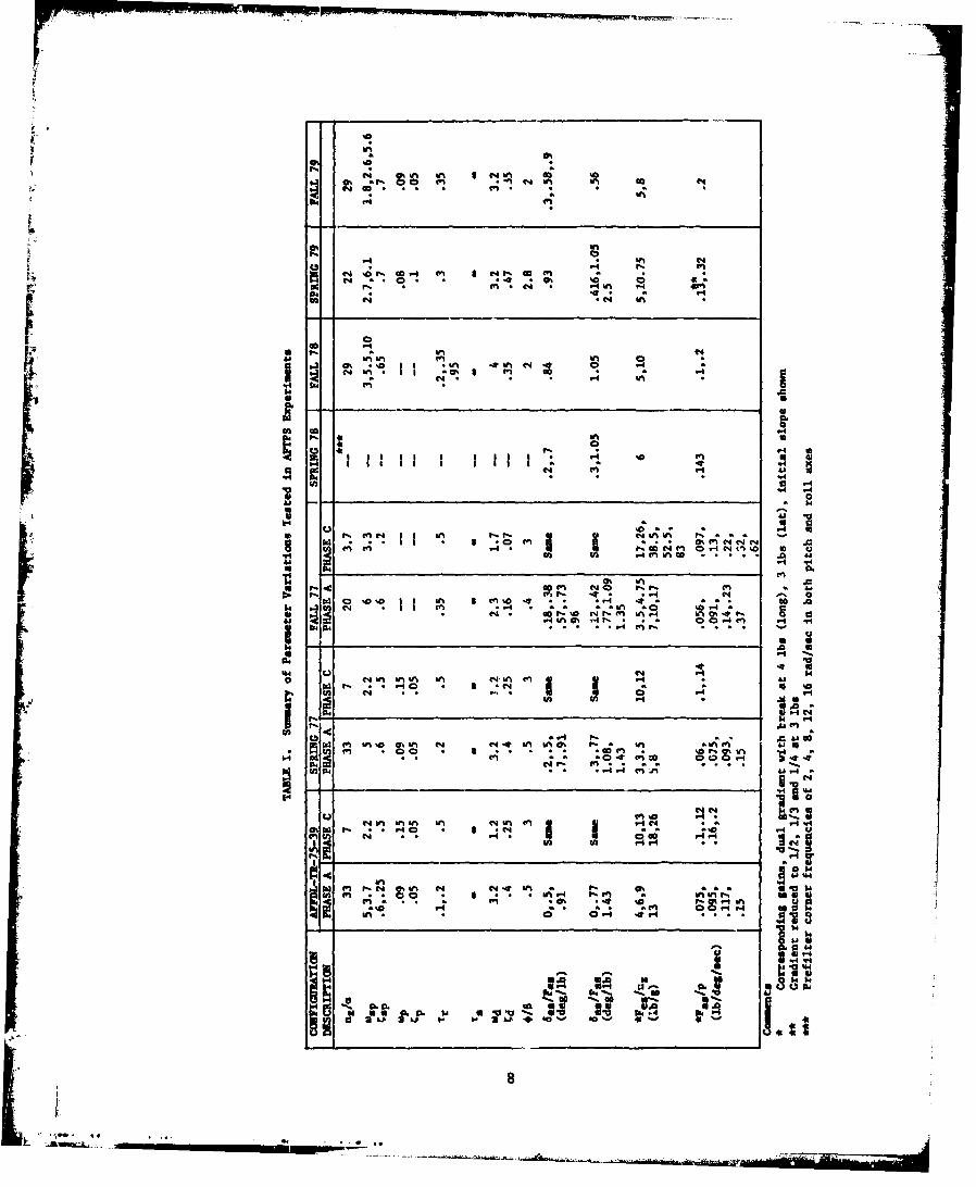
I Summary of Parameter Variations Tested in AFTPS 8
II Dynamic Characteristics of Test Aircraft 45
III Control Configurations 46
IV Evaluation Pilot Questionnaire 53
V Airframe Dynamics 82
VI Control Force Gradients 83
VII Control Deflection Gradients 84
VIII Test Configurations 107
IX Air-to-Air Dynamics Sets 133
X Pilot Cooper-Harper Aatings, Data Summery 141
XI Test Results Summary, Maneuver #1, Air-to-Air Tracking 143
XII Test Results Summary, Mp'euver #2, Air-to-Air Tracking 144X.IL Test Results Summary, Maneuver #3, Air-to-Air Tracking 145
XIV Pilot Preference Trend Summary 146
XV NT-33 Dynamics 158
XVI Phase I Teet Configurations 159
XVII Phase II Test Configurations 161
XVIII Phase III Test Configurations 161
XIX Pilot Ratings and Condensed Comments for Phase IConfigurations 164
XX Pilot Ratings and Condensed Comments for LightLtngitudinal Phase I1 Configurations 166
XXI Pilot Ratings and Condensed Comments for MediumLongitudinal Phase II Configurations 166
XXII Pilot Rating and Condensed Pilot Comments for Air-to-AirTasks with Use of Rudders (Phase II) 167
XXIII Pilot Background Information 167
ix
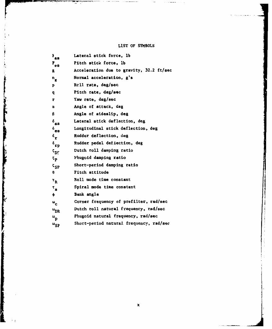
LIST OF SYMBOLS
I Lateral stick force, lbFas
F Pitch stick force, lbes9 Acceleration due to gravity, 32.2 ft/sec
n. nNormal acceleration, g's
p Rcll rate, deg/sec
Sq Pitch rate, deg/secr Yaw rate, deg/sec
Angle of attack, deg
a Angle of sideslip, deg
6 Lateral stick deflection, degas
& Longitudinal stick deflection, deges
a Rudder deflection, degr
6 Rudder pedal deflection, degrp
ýDr Dutch roll damping ratio
ýp Phugoid damping ratio
CSP Short-period damping ratio
o Pitch attitude
TR Roll mode time constant
Ts Spiral mode time constant
* Bank angle
we Corner frequency of prefilter, rad/sec
'•DR Dutch roll natural frequency, rad/sec
wp Phugoid natural frequency, rad/secp
w SP Short-period natural frequency, rad/sec
x
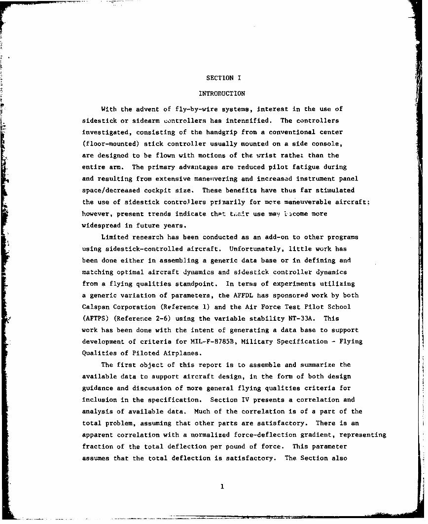
SECTION I
INTRODUCTION
With the advent of fly-by-wire systems, interest in the use of
sidestick or sidearm controllers has intensified. The controllers
investigated, consisting of the handgrip from a conventional center
(floor-mounted) stick controller usually mounted on a side console,
are designed to be flown with motions of the wrist rathet than the
entire arm. The primary advantages are reduced pilot fatigue during
and resulting from extensive manetivering and increased instrument panel
space/decreased cockpit size. These benefits have thus far stimulated
the use of sidestick controllers primarily for mere maneuverable aircraft;
however, present trends indicate thAt t~.-ir use ma\) ucome more
widespread in future years.
Limited research has been conducted as an add-on to other programs
using sidestick-controlled aircraft. Unfortunately, little work has
been done either in assembling a generic data base or in defining and
matching optimal aircraft dynamics and sidestick controller dynamics
from a flying qualities standpoint. In ternis of experiments utilizing
a generic variation of parameters, the AFFDL has sponsored work by both
Calspan Corporation (Reference 1) and the Air Force Test Pilot School
(AFTPS) (Reference 2-6) using the variable stability NT-33A. This
work has been done with the intent of generating a data base to support
development of criteria for MIL-F-8785B, Military Specification - Flying
Qualities of Piloted Airplanes.
The first object of this report is to assemble and summarize the
available data to support aircraft design, in the form of both design
guidance and discussion of more general flying qualities criteria for
inclusion in the specification. Section IV presents a correlation and
analysis of available data. Much of the correlation is of a part of the
total problem, assuming that other parts are satisfactory. There is an
apparent correlation with a normalized force-deflection gradient, representing
fraction of the total deflection per pound of force. This parameter
assumes that the total deflection is satisfactory. The Section also
11
indicates some apparent trends that require additional data for
verification. Section V presents guidance towards achieving a
satisfactory design of a sidestick controller for fighter ai.rcraft, with
an example design problem presented in Appendix A. Section VI is a
discussion of possible criteria for inclusion in the flying qualities
specification. The discussion is mainly s9,,eculation on the apparent
trends and tentative correlations presented in the earlier Section.
The results are also contrasted with the very limited amount of data
for transport configurations.
The reports of the AFTPS work have not been distributed, although a
preliminary su~mmary was presented at the 1978 AFFDL Flying Qualities
Symposium (Reference 7). A second object of the present report,
therefore, is to document those results. Appendices B-F contain thebasic data from each of the tests together with the technical discussion.
Each of the appendices is extracted from the appropriate AFTPS Letter
Report with minimal editing.
2

SECTION II
HISTORY
Aircraft sidesticks are really nothing new. The original Wright
Flyer could be considered to have a single-axis sidestick controller forcontrol of pitch; many of the Wright's earlier designs used this type
of controller. The first Wright aircraft sold to the US Army, however,
had the wheel and rudder controller arrangement first used by Glenn Curtiss.
This controller arrangement remains the prevalent arrangement today,
particularily on aircraft not designed for extensive maneuvering. The
other common arrangement, center stick and rudder, dates from Armond
Deperdussin's racing monoplanes of 1912 (according to Garber of theSmithsonian). This control arrangement quickly became the standard for
more maneuverable aircraft, and remains so today.
During the post WWII period, sidearm controllers were tried
experimentally as "formation sticks", on aircraft such as the XB-48.
In this capacity, they were used for gentle maneuvering by providing
inputs to the aircraft through the autopilot rather than through the
conventional flight control system. The conventional controls were
used for takeoff, landing and maneuvering the aircraft, and also when the
autopilot was not in use.
In 1957 the National Advisory Committee for Aeronautics (NACA) modified
a T-33 aircraft so that the front seat pilot could fly the aircraft with
a sidestick controller (Ref 8). This controller was independent of the
center stick but was usable as a primary flight controller. In this
design, roll control was from the conventional left-right rotation of the
stick, but pitch control was via an up and down motion of the stick,
pivoting about the wrist. This same arrangement was later incorporated
in the USAF variable-stability NT-33A for sidestick research conducted
during the early 1970's.
The NACA study found that the offset controller location was comfortable
to the pilot and that the aircraft was flyable with this arrangement. The
lateral arrangement was considered comfortable, but the use of vertical
displacement for pitching was "strange and uncomfortable especially when
large stick motions and high force levels are required".
3
*1. , * * .* • , o .- .•,*,.
The first operational aircraft to again use a cide3tick controller
to directly fly the aircraft was the X-15. In the X-15 arrangement,
the sidestick was coupled to the center stick "at the non-linear pitch
mechanism arm through the separate pitch and roll hydraulic boost
actuators in order to reduce aero (side) stick pilot control forces
and synchronize both stick displacements" (Ref 9). The intent of
the sidestick was to allow the X-15 aircraft to be more easily maneuvered
during longitudinally accelerated flight such as boost and re-entry. The
design of the sidestick was such, however, that it could be used at any
time during atmospheric flight at the pilots discretion.
Much of the development work on the X-15 sidestick was done on
a JF-101A aircraft in 1960 and 1961 (Ref 10). Once again a pitch pivot
at the wrist was used on the stick, with the roll pivot at the stick base.For this effort, a human factors study of wrist agility was also made to
define good pivot locations. The study was very extensive, and led to
several conclusions, including optimized pitch and roll gearings and
force-deflection gradients. These results will be discussed further in the
next section.
During 1966-68, the Air Force Flight Dynamics Laboratory sponsored a
pitch-axis fly-by-wire test program on a JB-47E. During the second
phase of this program a sidestick controller was mounted on the pilot's
(or copilot's) left side ejection seat arm. Evaluation pilots commented
favorably on the system, patcticularly the "ease and preciseness of control"
(Ref 11).
During this same time period, two F-106B aircraft were modified into
variable-stability trainers. These aircraft were flown with sidestick
controllers as well as the normal stick. Nothing further is known about
this project.
In 1969 the Martin Marietta Corporations's Baltimore Division under
contract to the Air Force Aerospace Research Pilot School (now Air Force
Test Pilot School) designed, built and installed a sidestick fly-by-wire
control system in two F-104D's. These aircraft were evaluated in flight by
ARPS. The results were reported at the 1970 annual symposium of the
4
Society of Experimental Test Pilots (Ref 12) and will be referred to in
the next section.
The USAF variable stability NT-33A aircraft has been used extensively
for flying qualities research. In 1974 it was equipped with a variable-
force, variable-motion sidestick controller as documented in Reference 13.
Experiments on this airplane form the main data base for this report.
At this writing the aircraft is configured with a base-pivot (pitch and
roll) stick which may be either fixed or displacable.
The first production aircraft to use a sidestick controller" is the
F-16. Both fixed and limited-motion sidesticks have been evaluated both
in the YF-16 prototype and the F-16A full-scale development aircraft (Ref 14).
Although the emphasis is toward fighter applications, sidesticks havebeen used as primary controllers on other classes of aircraft, too. A
sidestick design was used in the C-1, Fly-By-Wire Program (References 15
and 16). Reference 16 states that the human factors development of the
sidestick controller relied on results from References 10, 17 and 18.
Very few details are given of the sidestick characteristics finally chosen;
however, the aircraft with fly-by-wire control system was evaluated in a
variety of tasks. There was, apparently, little adverse comment about the
sidestick, In a similar application, a sidestick was included in an
experimental digital fly-by-wire control system evaluated by Aerospatiale
in the No. 1 Concorde (Reference 19). A problem with the installation was
that the left-hand sidestick and the right-hand throttles were farther
apart than desired. The total system, however, was evaluated as having
excellent handling qualities, in ten houre of flight test over a wide range
of conditions. Along with the earlier cited use as formation stick,
these examples represent application to large aircraft which are not highly
maneuverable.
On the other end of the spectrum, sidestick controllers are used il
two light aircraft (the Rutan VariEze and the Bede BD-5 series of aircraft)
and one experimental light twin (the Rutan model 40 Defiant which, incident,-
ally, uses a left-hand operated sidestick for the pilot and a right-hand
operated sidestick for the copilot). Qualitative evaluations have been
conducted on the BD-5 aircraft (both piston-engiaed and jet-powered,
Refs 20 and 21) ana" the results are also discussed in the next section.
5
SECTION III
DATA AVAILABILITY
The preceding section gives an indication of the number of programs
that have investigated sidestick controllers. In this section, we will
comment on the usefulness of the data to support development of flying
qualities criteria.
A. Published Data
The majority of programs discussed irn Section II, plus the references
available, have considered sidestick controllers for a specific application.
As such, the result is frequently a qualitative assessment or a single data
point. The physiological factors of neutral displacement, displacement
limits and force levels are available from these programs. The Calspan
study reported in Reference 1 is the only generally available report on
the interaction of airplane dynamics with sidestick controller
characteristics. In this study a general matrix of four response-force
values versus three force-deflection values was investigated f or a
peiddamping adincreased roll mode time constant were evaluated for
selected controller characteristics. This report was a start on acquiring
a generic data base for flying qualities applications.
B. Unpublished Data
Following the work reported in Reference 1, the Flight DynamicsI
Laboratory began sponsoring a series of experiments (References 2-6), also
using the variable stability NT-33A. These experiments were flown at theA
AF Test Pilot School as student projects. The projects were defined by
the students with guidance from AFFDL's Flying Qualities Group and
Calspan's project engineer. The student teams included both pilots andflight test engineers, with the pilots doing the flying qualities
engneeingsaftypilots, and also supported the aircraft operations.
Theresltsofthe flight test experiments were documented in Letter
ReprtstotheFlihtDynamics Laboratory. The first of these Letter
Repots as lsoissued as a Flight Test Center Technical Report, and a
summry f te frstthree was presented at the Flying Qualities Symposium
4. 6
in September 1978 (Reference 7). It was decided, howeve-, that the
indivicLoal Letter Reports would not be distributed because of the variety
of constraints under which they were produced. Although inexperience,
learning curves, time limitations, etc., tend to increase Blightly the
number of questionable data points as compared to a "pro~fessional"
study, the data is believed to be generally valid when viewed as a whole.
This data is therefore published in Appendices to this report. The
range of parameters tested *is indicated in Table I, and a short suimmary
of each of the AFTPS experiments follows:
Test by Class 76B (Reference 2, results presented in Appendix B)
A matrix of both longitudinal and lateral force and deflection charac-
teristics was evaluated in tasks representative of Flight Phase. Categories
A (precision and gross maneuvering) and C (approach and landing). The values
tested generally filled in the matrix tested in Reference 1 with the same
aircraft dynamics. There were, however, minor differences in the gradients,
the non-linearities and the breakout forces.
Test by Class 77A (Reference 3, results presented in Appendix C)I,
This experiment continued the previous tests but expanded the matrix toinclude more deflection and heavier forces. Included in the results is an
excellent discussion of the factors affecting the ratings for various side-
stick controller characteristics.
Test by Class 77B (Reference 4, results presented in Appendix D)
This test investigated the eifects of varying the corner frequency ofIfirst-order lag prefilters in both the longitudinal and lateral axes (identical
prefilters were used in each axis). The optimum response/force gradients
from the previous tests were used, with two values of deflection/force gradient.
Test by Class 78A (Reference 5, results presented in Appendix E)
This test investigated a matrix of three short period frequenc:i~es with a
medium roll mode time constant and three roll mode time coTnstants at a
medium short-period frequency. Controller characteristics were two response/
force gradients in each axis with a constant force/deflection gradient value.
r 7
00 0
-41
N CC
14 M C!0N -0* 00 91 -N 4V D t
,-.. .4 ( . In .- o ~ A
CC
U2 C4.tI N % 0% -4r 49- 4 "
NN19a
U, P11
-44Go 'A~~~c 0IH 1 1 H 1 'A
4.' -
in.' *aU
In kk ki -4

Test by Class 78B (Reference 6, results presented in Appendix F)
This test investigated a matrix of lateral force/deflection gradients
and force/response gradients against the two preferred pairs of longitudiual
short period frequency and sidestick force/deflection from the previous
experiment. Additionally, in the second phase, two non-linear longitudinal
f0rce/deflection gradient ratios were evaluated.
F9
I!J!
1;1"F " :... .c.. . . . . . .. : _ . . ., .: : . . .r •.. . . .: : ,.. . . • !• , • ",i• • " " ' • • • : ; 5 . -. . :• .. ,' ' '
SECTION IV
DATA CORRELATION AND %NALYSIQ
In this section, data frow several specific test programs shall be
shown and compared. Additionally, recormendations and conclusions from
these programs will he discussed where applicable. The test or research
programs to be addressed herein are primarily for the following aircraft:
JF-101A
BD-5 series
F-104D SSCS (Sidestick Control System)
F-16A (Movable Sidestick Evaluation)
NT-33A Sidestick Research Programs
A. Evaluation Tasks Used.
Prior to actually presenting and addressing the data, the tasks used
in the evaluations must be discussed as the use of the dita may be limited
by these tasks.
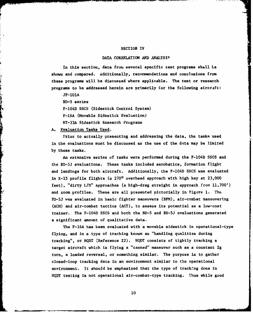
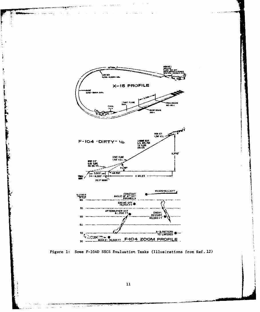
An extensive series of tasks were performed during the F-104D SSCS and
the BD-5J evaluations. These tasks included aerobatics, formation flight
and landings for both aircraft. Additionally, the F-104D SSCS was evaluated
in X-15 profile flights (a 2700 overhead approach with high key at 23,000
feet), "dirty L/D" approaches (a high-drag straight in approach from 11,700')
and zoom profiles. These are all presented pictorially in Figure 1. The
BD-5J was evaluated in basic fighter maneuvers (BFM), air-combat maneuvering
(ACM) and air-combat tactics (ACT), to assess its potential as a low-cost
trainer. The F-104D SSCS and both the BD-5 and BD-5J evaluations generated
a significant amount of qualitative data.
The F-16A has been evaluated with a movable sidestick in operational-type
flying, and in a type of tracking known as "handling qualities during
tracking", or HQDT (Reference 22). HQDT consists of tightly tracking a
target aircraft which is flying a "canned" maneuver such as a constant 2g
turn, a loaded reversal, or something similar. The purpose is to gather
closed-loop tracking data in an environment similar to the operational
environment. It should be emphasized that the type of track!ng done in
HQDT testing is not operational air-combat-type tracking. Thus while good
10
F77
X-16 PROFILE
IN I
t F-f04 -DiFPTY'* L/b
;; ~ ~ 14 MILEt*-~Zn
IOT nV Inoo~oocoy
5~~'.OO4 MILES SAR
so_ __ _ _ PARABOLA O ANEO O
-SO__ ____ PCAROFILE
Figure~~~~~~~~~~~~~~6.0 1:SmVT0DSC mla~v ak I1s~a~ rmRf 2
511
J

HQ)T tracking may imply gooc tracking handling qualities it does not
guarantee combat effectiveness. From a specification standpoint, however,
HQDT evaluations are wuch more closely related to operational use than
simply specifying open-loop parameters such as short-period frequency and
damping. Nevertheless, HQDT must be viewed simply as a method of generating
both qualitative and quantitative data on pilot preferences, workload and
task performance, not as an evaluation of operational excellence or
suitability.
For the JF-1O0A used in the X-15 sidestick development program, an
IFR 2-axis tracking task (similar to localizer and glideslope tracking
on a flight director) was used for evaluation. This data was gathered
both on the 6round (using the JF-101A as a fixed-base simulator) and in
flight. Additionally, sýwe landings were performed in the JF-101A using
the sidestick, though no quantitative data were gathered during approach
and landing.
The NT-33A has evaluated sidestick characteristics primarily in HQDT
tracking with some additional data gathered for basic aerobatics, approach
and landing tasks. This data is the most complete, comprehensive set
available; is presented in "raw" form in Appendices B-F. It should be noted
that the majority of this data has been generated during five student
research projects at AFTPS, thus some variability in the results is to be
expected.
D. Sidestick Deflection Geometry) Location and Control Switches.
The majority of the information available here comes from the F-104D
SSCS and the NT-33A. According to Reference 12, given a choice the pilot
usually will select "about 120 left, or inboard, of vertical (as a roll
neutral point). This is because of the limited freedom of the human forearm
to rotate in the outboard direction". Aircraft control. was deteriorated ifo 0
the pilot's hand moved "beyond 5 to 8 right of vertical". Additionally,
the pilots usually selected 170 forward pitch as neutral, or about 100 more
than the natural neutral position of the human wrist. Pilots selected this
in order to insure aft rotation capability, as this capability is very limited
from the wrists natural neutral position.
12
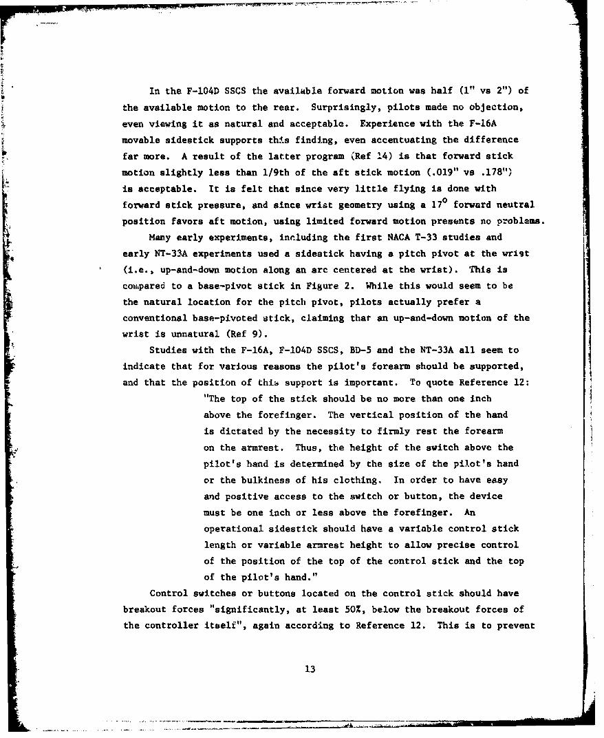
In the F-104D SSCS the available forward motion was half (1" vs 2") of
the available motion to the rear. Surprisingly, pilots made no objection,
even viewing it as natural and acceptable. Experience with the F-16A
movable sidestick supports this finding, even accentuating the difference
far more. A result of the latter program (Ref 14) is that forward stick
motion slightly less than 1/9th of the aft stick motion (.019" vs .178")
is acceptable. It is felt that since very little flying is done with
forward stick pressure, and since wrist geometry using a 17° forward neutral
position favors aft motion, using limited forward motion presents no problems.
Many early experiments, inrluding the first NACA T-33 studies and
early NT-33A experiments used a sidestick having a pitch pivot at the wrist
(i.e., up-and-down motion along an arc centered at the wrist). This is
coufpared to a base-pivot stick in Figure 2. While this would seem to be
the natural location for the pitch pivot, pilots actually prefer a
conventional base-pivoted stick, claiming that an up-and-down motion of the
wrist is unnatural (Ref 9).
Studies with the F-16A, F-104D SSCS, BD-5 and the NT-33A all seem to
indicate that for various reasons the pilot's forearm should be supported,
and that the position of this support is important. To quote Reference 12:"The top of the stick should be no more than one inch
above the forefinger. The vertical position of the hand
is dictated by the necessity to firmly rest the forearm
on the armrest. Thus, the height of the switch above the
pilot's hand is determined by the size of the pilot's hand
or the bulkiness of his clothing. In order to have easy
and positive access to the switch or button, the device
must be one inch or less above the forefinger. An
operational sidestick should have a variable control stick
length or variable armrest height to allow precise control
of the position of the top of the control stick and the top
of the pilot's hand."
Control switches or buttons located on the control stick should have
breakout forces "significantly, at least 50%, below the breakout forces of
the controller itself", again according to Reference 12. This is to prevent
13

Pitch Pivot at Wrist
Roll Pivot at Base
Figure 2: A Comparison of two Pitch and Roll Pivot Location Sets
14

unintentional control inputs during switch operation. Additionally, the
F-104D SSCS program found that force-connuand switches are unacceptable;
switches should have motion associated with their activation in order to
provide an instantaneous, positive indication of activation.
Some studies have indicated that identical dual control sticks, one
per side, should be used. The authors of Reference 12 suggested this.
However, no complaints have arisen in other sidestick programs so this is
not felt to be necessary.
C. Longitudinal Deflection-Force and Force/Response Characteristics.
It'should be stated from the outset that despite the use of a "fixed"
stick on the F-16 prototypes and full-scale development aircraft, all
available sources which have tested both fixed and "motion" suZcks in flight
have found that pilots definitely prefer motion sticks. The question to
be answered then becomes how much motion? The use of a fixed stick ispreferred in a fixed-base simulator, though, and it is felt some designers
have taken the attitude "if the pilots like it in the simulator they'll like
it in flight". Reference 10 further elaborates on this:
"The electric sidestick coupled with the MH-90X control
system was evaluated by twelve pilots from NASA, USAF,
Boeing Aircraft, McDonnell Aircraft and the USN. Five iflew the electric stick exhaustively to aisist in
determining optimum design parameter values. These five
evaluation pilots each had four to eight hours ground
time in the JF-101A cockpit. This ground time served two
purposes: (1) it provided valuable cockpit familiarization
for pilots who, although current in the JF-101A airplane,
did not routinely fly it. (Pilot familiarization with the
special cockpit equipment saved valuable flight time by
eliminating the false starts usually associated with new
equipment installations.) and (2) the function of this
ground time was to get pilot performance data during
simulated problem runs on the ground. In order to make
simulated problem tracking runs, a Reeves Electric AnalogComputer was connected into the autopilot giving a two-
axis simulation which could be controlled by either the
center stick or the electric sidestick.
15
"Problem tracking scores were 10 to 100 times poorer
on the ground than in the air. Since the most important
difference between the ground and air environments is
the acceleration and motion cues received by the pilot
in actual flight, it was concluded that these cues are
extremely important for precise tracking.
"Pilots showed a tendency to develop a special flying
technique on the ground, a bang-bang, pulse-type control,
particularly with the force stick, which was not at. all
typical of the control technique used in the air.
"In general, a very skeptical attitude was developed
toward the ground simulator work as a result of these
obeervations which was further reinforced by the pilot
opinion of the force stick. Every pilot who first flew
both the rigid force stick and the moving stick on the
ground simulator preferred the rigi,1 force stick over
th,' moving stick, both for maneuvering and trimmed
flight. However, after actually flying both stick
types through the tracking problems, every pilot reversed
his opinion preferring the moving stick for maneuvering
flight. Some pilots enjoyed flying the rigid stick in
low-demand flying, slow maneuvering, or trimmed flight;
but all pilots rejected it for the more demanding
tracking problems."
How much motion to use is a totally different matter. Experience
with the YF-16 indicates that for e given force/response gradient some
motion improves pilot opinion; however, additional motion degrades it.
This tends to indicate that an optimum range of deflection/force gradients
exists. The NT-33A sidestick experiments conducted by AFTPS for AFFDL
have attempted to isolate this area, and indeed have found a region of
longitudinal deflection/force gradients which appear to be good. The
reader is referred to Appendices B-D for the uncorrelated data.
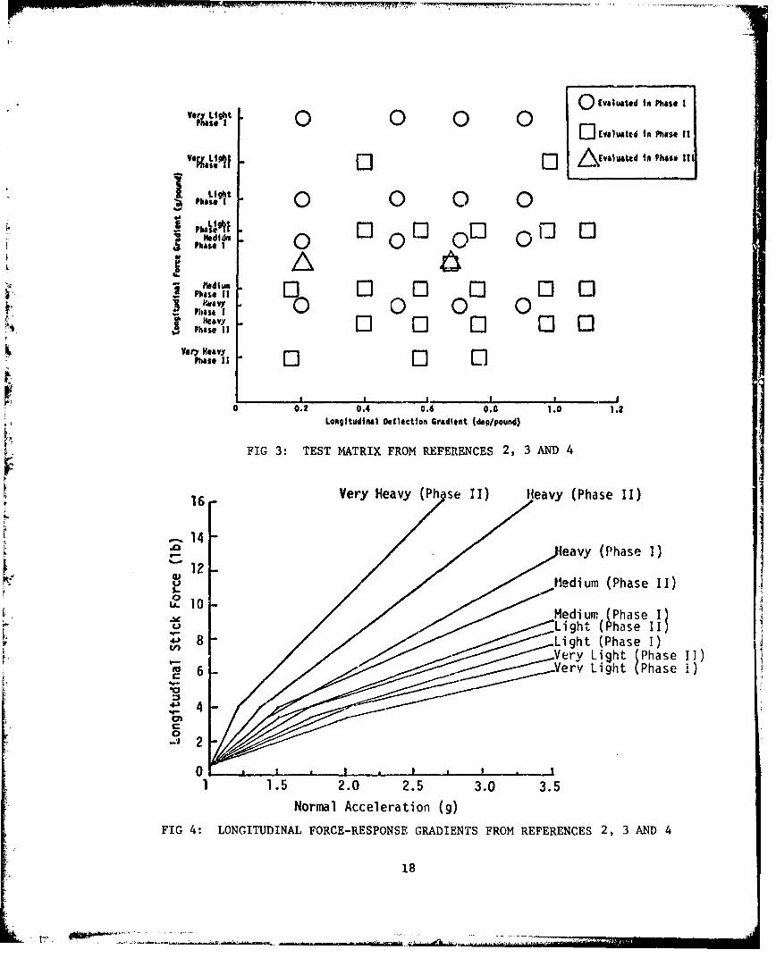
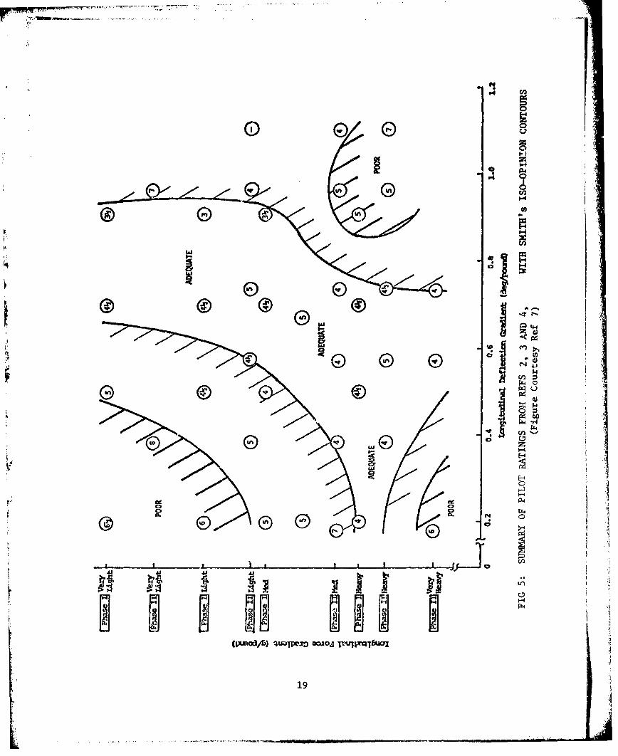
Reference 7 presented a summary of the data from the first three
AFTPS experiments, as well as some observations concerning the data.
16

Figures 3 and 4, from that reference, represent the configurations tested
and the corresponding longitudinal force/response gradients. Figure 5
shows the pilot ratings for the matrix of test conditions shown in Figure
3. Also shown are Smith's iso-opinion contours and evaluation of adequate
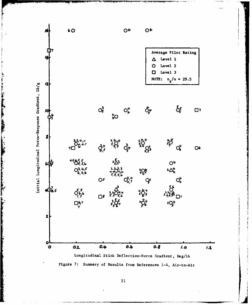
and poor regions. In the present report, we prefer to express the correla-
tion quantitatively in terms of the initial gradient of the force/response
curve. We have assumed that the pilot is most sensitive to the initial
slope for any task involving tracking. This parameter is not to be taken
as being independent of other characteristics. Acceptance of the initial
r slope requires that any change in the gradient and also the breakpoint be
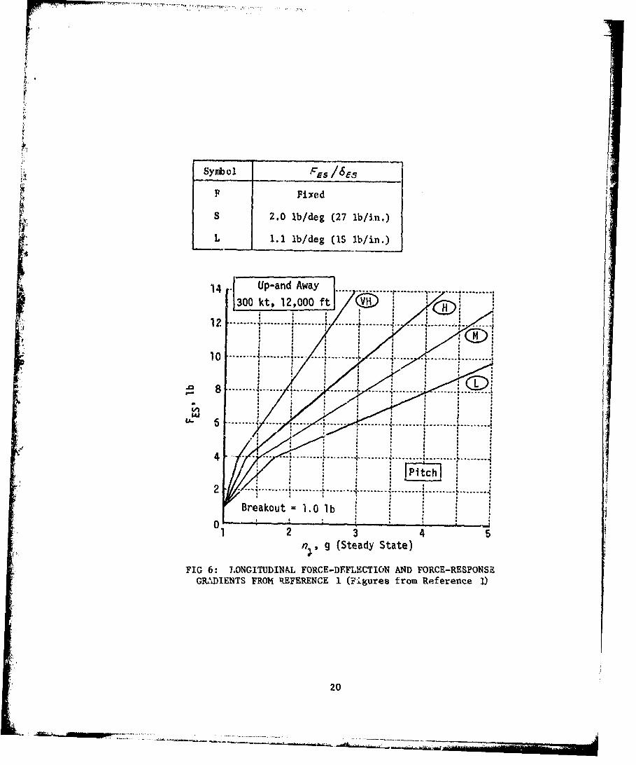
compatible, as discussed later. Taking this approach and adding the data
from Reference 1 (Figure 6) yields Figure 7. Notice that each individual
pilot rating value is shown. The most obvious interpretation of these
results is that there are no well-defined boundaries to be drawn.
The F-16A movable sidestick is not in any area of acceptable ratings in
Figure 7. Calculations based on Reference 14 place the F-16A movable side-
,. stick deflection/force gradient at 0.065 degrees per pound, far belowrecomme-nded values. Still, Reference 14 indicates that pilots expressed a
preference for the F-16A movable sidestick compared to the standard fixedI' stick. Although actual pilot opinion ratings were not given, we have
treated it as Level 1 because of the improvement over the fixed stick that
is in operational use. The answer may lie in using the technique suggested
by Duprey (Ref. 23). In evaluating data from several sources, Duprey found
it convenient to use normalized stick deflection/force gradients. For the
longitudinal axis this normalized gradient consists of the actuail longitud-
inal stick deflection/force gradient divided by the available stick deflec-
tion from the neutral position to the full aft position. The resulting
parameter, in inverse pounds, is then equivalent to the fraction of stick
deflection per pound of applied force. It will be referred to during the
remainder of this report as the "normalized deflection/force gradient".
The inverse of this parameter is just as meaningful - being the force if
the initial deflection/force gradient were continued to the maximum deflec-
tion. This is not the same as the maximum force if there is a break in the
gradient, and it would be necessary to distinguish the two. We have, there-
fore, used the normalized gradient.
17J
0 Evaluated in Phase Iv.p•• 0* 1 0 0
Ver~ ight() C) ()C.) JcvauAttd In Phis* It
jEvaluated in Phase 11ti
,h.,.t 1 0 0
V"' O0id 00 0 [ [Phase 1 0 0 0
Pas 0Hedid.s vLI0 0 ~ 0
phas if 0 0 0Very Heavy El
Phas 1 0 El
0 0.2 0.4 0.6 0.0 1.0 1.2Longitudinal Detlection Gradient (deg/pound)
FIG 3: TEST MATRIX FROM REFERENCES 2, 3 AND 4
Very Heavy (Ph se II) Heavy (Phase II)
14
eavy (Phase I)12
/Medium (Phase II)
U_ 10Ae Mdiumn (Phase I)
"o / •Light (Phase IILight (Phase I)
-:J 2
0' V..ry Light (Phase . II)•
1 1 .5 2.o 2.5 3.0 3.5
Normal Acceleration (g)
FIG 4: LONGITUDINAL FORCE-RESPONSE GRADIENTS FROM REFERENCES 2, 3 AND 4
18
P4 f
fri
_ _ _ _ _ _ _ _ _ _ _ KiIn Co
IJ
E) G
'V>
41ifTC
Fqz
-N .odA HOPZ wj l]rT
19a
£r
Symbol Es /655
F ~Fixed
S 2.0 lb/deg (27 lb/in.)
L 1.1 ib/deg (15 lb/in.)
: A.1 . . . .............. ... . ..........., ,
3012o1v00f
*M
•.• 12 .~~........ I ......... i ....... . ....... , ..... ....,./ .. ' ........ :.. ........ .......I0 . .. ... .. .. . .'. .. .... . .. . .. .... : ....... .......d . ... ......
" 4 .. . . .. .... . ........... .. ......... .......i • ....... , ..............
10
; ,
'u- 6 .. .
Braku g (Stad lbate)
1 2 4
FIG 6: LONGITUDINAL FORCE-D1EFLECTIOiN AND FORCE-RESPONSEGRADIENTS FROM REFERENCE 1 (Figures from Reference 1
20
40 04, 04-
i7
] ? Average Pilot Rating
A Level 1
0 Level 2
03 Level 3
NOTE: nz/a - 29.5
04)
-S
I V40 3 04 |
r. 03.4o5' 35o 0 ,4
-4:
7 r-
M 3
Longitudinal Stick Deflection-Force Gradient 2 Deg/Lb
Figure 7: Summary of Results from References 1-4, Air-to-Air
21
7j

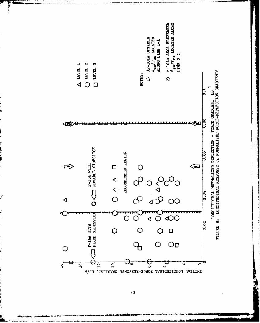
Figure 8 represents a recasting of Figure 7 based on this method. The F--116A movable sidestick (a normalized deflection/force gradient of 0.0335 lb-)
and JF-1OIA (0.0561b ) points are also shown on this figure. Results from
the F-104D SSCS program qualitatively support this method; the heaviest-1stick force gradient when normalized resulted in a value of 0.081 lb ; Ref-
erence 12 ind.,.ates that the high forces (i.e., this force gradient) are
acceptable for most tasks and adds, "As a general comment, we have under-
estimated the strength of the pilot". Therefore, a usable region of .03 lb1r -i
to .08 lb seems plausible at this time, with the lower portion of the range
being favored. We postulate, then, that the 'optimum' is actually a norm-
alized region. This result would also require thatthe stick neutral position
and total stick travel be within allowable ranges which need to be defined
of course. Recommendations for neutral position and maximum stick travel
are discussed in this report, which leaves the possible requirement to define
mimimum allowable stick travel. We may speculate that it is likely to be a
very sensitive function of airplane configuration and mission. In terms of
general guidance, we suggest that the stick travel must be enough to b•
easily perceptible to the pilot and sufficient to form a definite rf. at the
travel limits.
During the NT-33A experiments, breakout forces of 1/2 lb were used and
found acceptable. Conflicting data exists concerning the use of higher
breakout forces; References 12 and 14 indicating no problems while Reference
2 disfavors them.
Two-segment pitch force/response gradients have been evaluated on the
F-16A (movable sidestick) and the NT-33A. On the NT-33A, a halving of the
stick force gradients for forces greater than about 3 lb (absolute) stick
force was used. During the spring 1979 AFTPS project (Ref. 6) 1:1 and 4:1
longitudinal gradients were also evaluated and appear to be unacceptable.
D. Effects of Short-Period Dynamics
As an example of the interdependence of many parameters, Figure 8 might
be used to suggest a range of 4 to 15 lb/g as being acceptable for the
initial longitudinal force/response gradient if it were considered an inde-
pendent parameter. In fact, the acceptable range has been found to be a
function of airplane dynamics, i.e. short period frequency. During the fall
1978 AFTPS experiments (Ref. 5) three different short-period frequencies
22
or!
H~~E C44~ ~0-T0)G)
U)UE-4H
0 0
E-z4
0 P4
N
E-4%0 114
0 DotE-1-w
1''~ Ot-4OH
1-4~
1-4 H
0N
H H H4 H '0 -
V/g'I '1NIcRIav giNoaSqU-a3go'a rIVNIC~flII3NO'I qLINii
L 23

(2.6, 5.2 and 10 radiansisecond) were evaluated against two different
longitudinal force/deflection gradients (5 and 10 lb/g, with the
gradients halved at 3 lb absolute) for Category A tasks. For the NT-33A's
nominal value of nz//a (29.5g/rad), according to the current MIL-F-8785B
(Reference 21) 2.6 radians/second is Level 2, and 5.2 and 10 radians/second
are Level 1. With the sidestick controller, however, the 10 radians/second
short-period was rated as Level 2 with the comment that it was too fast.
The 2.6 and 5.2 radian/second short-peridd frequencies were rated Level 1,
but only when paired with 5 and 10 lb/g stick force gradients,
respectively. During the spring 1979 experiment, the 2.6 radians/second
and 5 lb/g configuration was further identified as the preferred longitudinal
configuration, based on preliminary data. It may be conjectuiad that the
preference for lcwer frequencies reflects the absence of forearm and stick
inertia effects which would be present in a center-stick-controlled
aircraft. In commanding a rapid pitch input to such an aircraft, the
pilot must overcome the inertia of his arm and the stick, thus he wants
a "fast airplane" to make up for the filtering effect of his arm and
the stick. In fine tracking with a center stick the pilot will rest his
arm, typically on his knee, to reduce this problem. The inertia of the
center stick is still greater than for a sidestick, so that we may still
expect an effect even in fine tracking. When using the sidestick, however,
these effects are not present so that a higher-frequency airplane seems
to have a more abrupt response to control inputs. The pi )t now prefers
the airplane itself to act as a filter, smoothing the responses to his
inputs. Thus, the pilots may prefer a lower-frequency aircraft when using
a sidestick, compared to the preferred frequencies using a center stick on
which MIL-F-8785B is based.
lased on private conversation with the authors, Chalk feels that this effect
can similarly be addressed by a criterion on peak pitch acceleration response
t9 stick force, 0 " ax Reference 25 elaborates on this and the idea alsoF. m
is discussed in Section VI of this report. Additionally, the work of Smith
and Geddes (Reference 26) may be applicable, if one considers a lower
airplane 6hort-period frequency as a filtering effect on pilot inputs.
24
L.....-• J •••
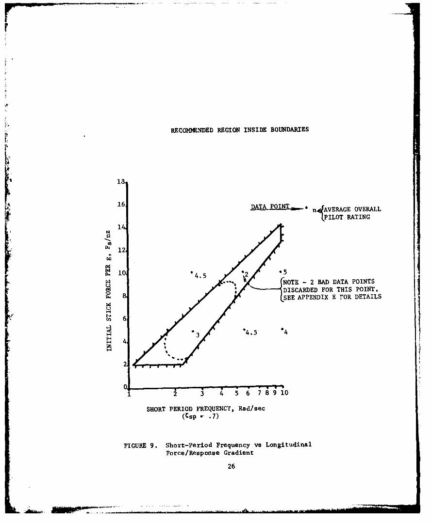
The data from the fall 1978 AFTPS experiment and a suggested range of
short-period frequencies versus longitudinal stick force/response gradients
is shown in Figure 9. References 20 and 21 suggest the lower Fs/nz boundary,
while Reference 5 suggests the lateral and upper boundaries. Preliminary
data for the 2.6 and 5.2 radians/second short-period configurations generated
during the spring 1979 AFTPS experiment (Ref 6) suggest that the recommended
region may be smaller than first thought. This is shown by the dotted lines
in Figure 9.
E. Roll Deflection/Force Gradients, Response, and Control Harmo.
During the first four AFTPS student projects or. the NT-33A, pilots
consistently complained about directional wandering and "pendulum" effects
(i.e., the tendency of the pipper to oscillate like a pendulum because the
pilot's line of sight through the pipper is below the roll axis of the aircraft).
There is thus an additional question mark which needs to be placed against the
lateral-directional results.
During the spring 1979 AFTPS experiment several lateral deflection/force
and force/response gradients were tried with two previously liked sets
of longitudinal dynamics and gradients (Ref 6). These data are shown
in Appendix F. Based on these and previous data several observations
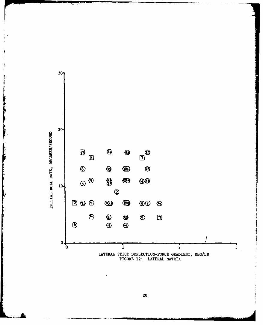
can be made. Figure 10, taken from Reference 7, summarizes the lateral
force/response gradients used on the NT-33A during the first three experi-
ments and figure 11 shows the same data from Reference 1. Figure 12 shows
pilot ratings for all the lateral force/deflection gradients from References
1-6. Rather than attempting to form iso-opinion contours for the results
shown, it was decided to try a normalizing technique analogous to that
used longitudinally. If this procedure is employed,
an acceptable range of lateral normalized deflection/force characteristics
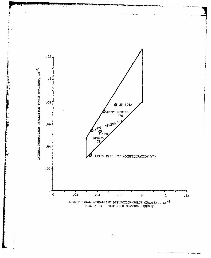
is indeed found to exist. In Reference 4 an "optimum" configuration
("configuration X") is recommended; its normalized gradient is found to be-1.0325 lb . It should be noted that this number is obtained by using the
total center-to-left-stop deflection of 200, a soft stop is used at 120
when moving the stick to the right though the deflection/force and force/
response gradients are symmetric. Data from the first AFTPS experiment
(Ref 2) indicate preferences for values of .054 lb with a longitudinal
normalized deflection/force gradient of .035 lb-, and values of .0715 lb- 1
25
RECONNENDED REGION INSIDE BOUNDARIES
13161 DT ON
1 DATA PUNT n AVERAGE OVERALL
(1PILOT RATING
14
~12
4 1 4.5 '2NOTE - 2 BAD DATA POINTS
0 8*DISCARDED FOR THIS POINT.8 SEE APPENDIX E rOR DETAILS
P 6 3 4.5 4
-4z
2
in1 4 5 6 7891
SHORT PERIOD FREQUENCY, Rad/sec(Csp - .7)
FIGURE 9. Short-Period Frequency vs Longitudinal
Force/Response Gradient
26
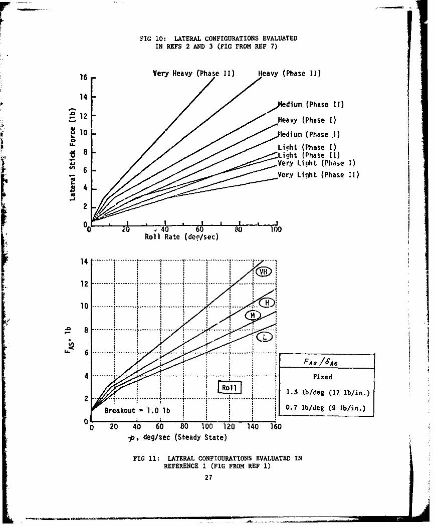
FIG 10: LATERAL CONFIGURATIONS EVALUATEDIN REFS 2 AND 3 (FIG FROM REF 7)
16 Very Heavy (Phase II) Heavy (Phase II)
,,)*ium(Phase 11)
Heavy (Phase I)
S10 *lediun (Phase .1)
Light (Phase I)•, i 8 / / / / / Light (Phase 11)
4 6 'Very Licht (Pha~ie 1)Very Light (Phase II)
2
000 .40 60 so 100
Roll Rate (deg/sec)
14......... ..................14 [ ........................................................... ... . ..... "
12 . . ........... . .. .... .. .. . -- --- .... .L ... .. *0 ... & . . ........ ... ..
8 .- -. --- -- -- ---.. ..... 4 ,- .. .. ... .. . .
6 ... .. .. . .. .. . ... .. .. . .' .. .. .. .. , ... .. . .. ..
I~A I I I
4 ..... / i •......... . . . ........ }......... .... ........ " ......... Fixed
,1.3 b/deg (17 Ib/in.)I .. ...... . ...
Braku 1. lb 0.7 lb/deg (9 1b/in.)
I I I0
0 20 40 60 80 100 120 140 160- deg/sec (Steady State)
FIG 11: LATERAL CONFIGURATIONS EVALUATED INREFERENCE 1 (FIG FROM REF I)
27
* I * * I
* I I *I
30
20-
L~J
ini
00 'i2 3'
LATERAL STICK DEFLECTION-FORCE GRADIENT, DEG/LBFIGURE 12: LATERAL MATRIX
28 4

with a longitudinal gradient of .0455 lb~1 provided the "light" control
force/response gains are used (5 lb/g initially, which is confirmed by
References 5 and 6). On the JF-10lA, a value of .0778 lb1 (with .056 lb-
le-gitudinally) was preferred, though performance was slightly better with
I ier forces yielding a normalized lateral gradient of .0515 lb 1 The
preferred values from Reference 6 are .0418 lb- luligitudinally and .0526
-.1lb laterally. All of these are shown graphically in Figure 13.This evidence seems to point toward a pilot preference for a lateral
normalized deflection/force gradient ranging from the same as to about 60%
higher than the longitudinal normalized deflection/force gradient. Again,
as in the pitch axis, pilots liked 1/2 lb breakout forces (Ref. 2).
The use of nonlinear roll response has been evaluated on the NT-33A
projects conducted by students at AFTPS. All experiments except the spring
79 experiment used a halving of the force/response gradient above 3 to 4 lb
absolute stick force. During the spring 1979 experiment (Ref. 6) gradients
of 4:1 and 6:1 were also used. These gradient changes were evaluated as
being too abrupt in their responses to a pilot input, in comparison with
the 2:1 gradient change, and should be considered unacceptable.
Results from the NT-33A projects indicate that in roll response, as
in pitch, the aircraft should be at the maximum response when the control
stick reaches a stop. That is, the aircraft should be at maximum available
or allowable roll rate at full side deflect~ion of the stick. The use of"1soft stops" is not recommended; stick stops should be unmistakably dis-
cernible to the pilot. This again leaves a requirement to define the mini-I
mum acceptable lateral stick travel.
Analogous to the preference for lower short-period frequencies insidestick-controller aircraft is a preference for a roll mode time constant
slightly higher (i.e., slower) than the minimum value tested. Reference 5
indicates that the preferred value may be around .35 seconds. A value of
.3 seconds was used during the spring 1979 AFTPS student project (Ref. 6);
results indicate no negative pilot comments concerning roll response.
F. Trim Systems.
The current trend is toward series trim systems where the geometric
stick neutral (i.e., center) point remains constant. By contrast,
29
.12
.0/
•' .12
.08 JF-101A
0H• AFTPS SPRING
'76
S.06
?FTPSSPRING
.04 '79.04
SAFTPS FALL '77 (CONFIGURATION"X")
.02
0 .02 .04 .06 .08 .1 .12
LONGITUDINAL NORMALIZED DEFLECTION-FORCE GRADIENT, LB- 1
FIGURE 13: PREFERRED CONTROL HARMONY
?0
requirements for constant normalized stick deflection/force gradients,
constant lateral and longitudinal normalized gradient ratios and hard
stick stops would tend to favor the use of parallel trim systems. In
a parallel trim system the stick center position varies with trim set-
p ting. (For example, say a pilot were to place the aircraft in a 2g trimrequiring 3 lb back pressure on the stick and correspondingly 1 1/2
degrees of back motion from the lg neutral point. When he trims out the
3 lb force, the stick will still be 1 1/2 degrees aft of the lg neutral
point.) This preserves the recommended requirements independent of trim
setting.
G. The Use of Prefilters.
A prefilter is a control element between the controller and the
control surface actuator. Its purpose is to filter out higher-frequency
pilot inputs, yielding a smoother command input to the aircraft. All
AFTFPS experiments were performed with a 16 rad/sec prefilter, except the
spring 1978 experiment which evaluated other prefilter frequencies (Ref.
4). This reference indicates that given good deflection/force and response
characteristics, pilots prefer the highest frequency prefilter available,
i.e., the minimum amount of filtering. The handling qualities analysis
work of Ralph Smith (see Ref. 26), however, indicates that pilot ratings
will be improved if high frequency peaks in the amplitude response can be
filtered out without adding phase lag. This matter has not been pursued
further, and would be a candidate for future thought or work. The use of
a "lower frequency" aircraft would need to be evaluated in terms of the
total airplane system requirements and performance.
31
J 'JWf T
SECTION V
DESIGN GUIJDANCE
Based on the data available at this time, it seems that it is possible
to synthesize a good sidestick controller design for a fighter aircraft with
a reasonable degree of confidence. The recommendations for the design
follow.
a. Basic Aircraft
The aircraft would be acceptable with a lower short-period
frequency than would be deduced from the current MIL-F-8'85B requiremants.
The roll-mode time constant may have a minimum acceptable value in addition
to the current MIL-F-8785B requirements. This may, however, apply only to
maneuverable aircraft (i.e., fighters).
b. Neutral Position
The neutral position of the sidestick should be oriented so
that in wings-level unaccelerated flight the pilot need never move his
wrist further aft than 5-70 forward of vertical to command maximum permis-
sible load factor, or further outboard than 50 right of vertical to command
maximum roll rate to the right.
Available data would tend to support a neutral position of 100
to 170 forward of vertical and 8* to 120 left (inboard) of vertical, pro-
viding the constraints of the first point under this heading are not vio-
lated. A pilot adjustable armrest is absolutely mandatory, and its design
can influence pilot acceptability as much as any other parameter.
c. Breakout Forces
Breakout forces should be no greater than 1 lb and no less
than 1/2 lb.
d. Control-Stick-Mounted Function Switches or Buttons
Jmy switches, buttons, trim switches, etc., mounted on the
control stick should have breakout forces no greater than 50% of those
used for the control stick itself.
e. Control Stick Motion
Fixed sticks are satisfactory only for commanded pitch-down
motions. The minimum recommended pitch-up deflection is 20 from neutral
to full aft.
Lateral deflection limits should be consistent with longitudinal
limits.
32

f. Longitudinal. Force/Response Gradient gain hudb
Th nta ogtdnlfre/epnegain hudb
determined from the recommended region of Figure 9 of this report, given
a known aircraft short-period frequency.
Nonlinear gradients are preferable with the final slope less
than or equal to twice the initial slope.
g. Lateral Force/Response Gradient
Nonlinear gradients are acceptable if the final slope is
less than or equal to twice the initial slope.
h. Longitudinal Deflection/Force Gradient
The aft longitudinal deflection/force gradient divided by the
total available deflection from the neutral position to the full aft
position should lie in the range of .03 lb 1 to .08 lb ,with the lower
portion of the range being preferred.
The forward longitudinal deflection/force gradient may be as
little as 1/9th the aft gradient based on Reference 14, though more
symmetric gradients would be encouraged for larger stick deflection ranges.
i. Lateral Deflectior'/Force Gradients
The lateral deflection/force gradient divided by the total
available deflection from the neutral position to the full left or right
deflected position should lie in a range of 1 to 1.6 times the lon~gitudinalInormalized deflection/force gradient.
Symmetric left and right gradients through neutral are
recommended, although we retain the possibility that lower maximum force
and deflection to the right may be accepLable.
J. Stick Stops
Hard stops should be employed; i.e., full or maximum allowable
airplane response should occur when the stick reaches maximum deflection
for the nppropriate command. These stops should be easily discernible to
the pilot.
k. Trim Systems
Based on items (h, i and J) in this section, parallel trim
systems are speculated as being most appropriate.
33
SECTION VI
IMPLICATIONS TO THE FLYING QUALITIES SPECIFICATION
Results given in the preceding. Sections show that various
requirements need to be evaluated for the impact of sidestick controllers.
The current edition of the specification (Reference 24) does not contain
any reference to sidestick controllers. The proposed MIL-F-8785C contains
only minor references to them, so that all i'equirements are open for
consideration.
A. Force and Deflection Limits.
The deflection limits discussed in the preceding sections may be
considered candidates for the Level 1 boundaries. By contrast with existing
requirements for wheels and center sticks, we now may need to consider an
allowable range of neutral positions. Vertical to 120 inboard for roll,
and vertical to 170 forward in pitch, are suggested ranges. It is not
clear, however, that this is an item that needs specification as a flying
qualities requirement. Maximum force and deflection limits could be set by
anthropomorphic considerations. MIL-F-8785B currently sets a wheel throw
limit for roll control, and could add analogous limits for sidesticks for
both pitch and roll.
B. Pitch Response Characteristics.
The pitch results contain two separate factors, viz the selection of
higher force with the higher short-period frequency and the apparent
selection of a lower range of acceptable short-period frequencies for
sidestick-controlled aircraft. The first of these factors is in line with
prior data and could be correlated by a parameter such as pitch acceleration
(or load factor) due to stick force. MIL-F-8785B contains limits for
minimum stick force per load factor, but not recommended values.
The short-period parameter wn/na is approximately equivalent to
* max /n I 'the ratio of initial pitch acceleration to final steady
state normal acceleration response for a step command, independent of the type
of controller. This parameter is affected by the second of the results
listed. If the indication of a different choice of short-period frequencies
for sidestick is valid (i.e., verified by further data), then this implies
revision of the specification is needed. On a first level, this revision
could be accomplished by empirical correlation of new values for w / na.
34
Sufficient data would need to be accumulated to give consistent,
substantiated boundaries.
We may also speculate on a more fundamental level on the cause of the
indicated trend. Consider again the meaning of parameter 2/na specified
in MIL-F-8785B. Now the data being evaluated is for an elevated-g
tracking task, where the steady-state response to a control input may not
have much meaning since the pilot is continuously adding control inputs.
This is consistent with the conjecture put forward in Section III of this
report, i.e., the inertia of the pilot's arm and controller is a factor in
the response. This would only be true in a high-frequency, highly dynamic
situation, probably Class IV (fighter) configurations in Category A Flight
Phases (e.g. air combat or weapon delivery). A limited amount of data is
also available in Reference 28. These ground-based simulation results for
a sidestick-controlled Class III (transport) aircraft in landing approach(Category C) show good agreement with MIL-F-8785B values for wn/na. Theseflight phase conditions would not be expected to impose any requirement
for abrupt maneuvering, supporting the thesis that we are attempting to
explain an effect of maneuverability.
Reference 29 proposes the existence of a "flying qualities nerve".IIThe parameter coq is proposed as the output of this nerve in response to
pitch rate. The hypothesis suggests we are searching for requirements ona parameter such as O/OBq* If such a transfer function existed, it would
contain "physical lags" such as the effect of arm inertia, in addition to
the parameters normally included in pilot models. This extension is pure
speculation. It is concluded, however, that the current short-period
frequency requirements in MIL-F-8785B may need revising for sidestick
controllers in Class IV aircraft in Category A Flight Phases. Sufficient
data is not currently available to accomplish this.
C. Roll Response Characteristics.
The results on roll mode time constant imply an effect similar to that
discussed for short-period characteristics. Heavier forces are selected
with the more sensitive configuration having a lower roll mode time constant.
In addition, a definite preference was stated for the medium roll mode time
constant of 0.4 secs, in Reference 5, although all the values tested
(0.2, 0.4 and 0.9 seconds) are within the Level 1 requirement of NIL-F-8785B.
35
1A
Reference 1 on the other hand shows pilot ratings of 3 for both 0.2 and
1 second. The Level 1 requirement in MIL-F-8785B is only for a maximum
value of 1.0 second, whereas the results imply that a minimum value may
also be appropriate. The requirement for a minimum roll mode time con-
stant is probably a more general one which has not previously been a
problem in practice. Now with an electric sidestick controller and fly-
by-wire control system these low time constants can be achieved in the
response to stick input, thus we need to consider this as a specificationU item.
IL
36
SECTION VII
CONCLUSIONS AND RECOMMENDATIONS
This report presents previously unpublished data and attempts to
correlate it with existing data on sidestick controllers as applied to
aircraft flying qualities. The objectives were to formulate design
guidance and to discuss possible impacts on the existing military flying
qualities specification. The ideas of normalized deflection/response
gradients and optimal values for these gradients have been presented along
with data and rationale to support the ideas. A possible interaction
between the longitudinal force/response gradient and the aircraft short-
"period frequency has been presented. Finally, recommendations have
been made concerning the stick neutral position and allowable deflections
based on available data.
It is stated as a conclusion of this report that sufficient data exists
at this time to form design guidelines and to suggest that revision of
the current flying qualities specification may be needed. For design
guidance recommendations, the reader is referred to Section V of this
report. Possible specification revisions are discussed in Section VI.
It is felt that there is still insufficie:t data to substantiate any
revisions at this time.
In the data reviewed for this report, five potential areas for future
research became apparent. They are:
1. Further exploration of the interaction between short-period
frequency and controller force/response characteristics,
2. Further research to validate th(! concept of normalized deflection/
fcrcp gradients and to define acceptable/unacceptable ranges of lateral
to 7'otudinal gradient ratio,
3. The use of nonorthogonal or skewed sidestick axes,
4. Optimizing the neutral position of the controller,
and '. The use of nonsymmetric roll deflection/response gradients.
.comment on the relationship of items 2, 4 and 5 Is necessary here.
In light of the apparent preference for a lateral to longitudinal normalized
gradient ratio of between 1:1 and 1.6:1 it appears that nonsymmetric roll
37
.1L . -.-
gradients would be excluded. It is possible that the disadvantages (if any)
of this can be overcome by properly positioning the stick such that the
pilot need never move his wrist further than around 50 outboard of
vertical. This would seem to be preferable to using nonsyumetric roll
deflection/response gradients.
L
38
APPENDIX A
A SAMPLE DESIGN PROBLEM
In this section, a sample design for fighter application will be
formulated, Rationale will be given for the various choices.
First, for the critical flight condition it will be assumed that
the short-period frequency is around 3.5 radians per second and the roll
mode time constant is .3 seconds. This is in the recommended area from
the AFTPS experiments, as discussed in Sections IV-D and E of this report.
A base-pivoted two-axis sidestick will be used. A pilot-adjustable
armrest will be included in the installation. The neutral position will
be chosen to be 150 forward and 100 left of vertical. These numbers are
approximately in the center of the preferred region. Breakout forces of
0.8 lbs will be used, with control switch breakout forces of 0.4 lbs.
These choices are in accordance with the discussion in Section IV-B.
The stick force/airplane response relationship is defined by the
choice of certain basic parameters. The force/response gradient
through zero should be appropriate to the tracking task and the maxi-
mum force should be consistent with the maximum response. If a break
in the slope is required then this should be at a response level just
above what is required in normal tracking, although it is expressed
herein in terms of a break force as being a more convenient design
parameter. Also, although this example is written in terms of a
critical flight condition, an actual design would have to be evaluated
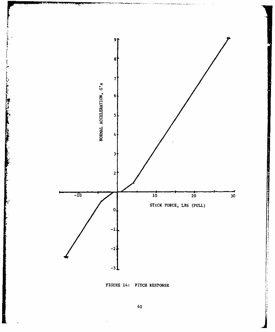
over the whole flight envelope and tailored as necessary.From Figure 9 of this report, the recommnended initial pitch force/
response gradient for aft deflections is found. A value of 7 pounds per
"g" is selected. As discussed in Section IV-C, the gradient will be halved(to 3.5 lb/g) at 4 lb (absolute) stick force. This variation is presented
graphically in Figure 14. A 28.5 pound pull force will command 9 g's,
which is assumed to be the design load limit.
Now a requirement for a longitudinal normalized deflection-force
gradient of .03 lb to .08 lb- is imposed. Based on the discussion inSection IV-C, a value of 0.035 lb 1 is chosen. Also, at this time, an aft
deflection limit of 10 (from neutral) is chosen. Multiplying these two
values and inverting yields the aft longitudinal force/deflectior gradient
of approximately 2.86 lb/deg.
39
8,
7
r 60
44 5
40
3
2
-10 10 20 30
STICK FORCE, LBS (PULL)0
-21
-3j.
FIGURE 14: PITCH RESPONSE
40

The forward deflection limit has not yet been discussed. As discussed
in Section IV-C of this report, the forward deflection limit need not be
identical to the aft limits. The same pitch force/response gradient will be
maintained by choice, as well as the same normalized deflection/force
gradient. A limit of -2.6 g's is used, and the resulting force at this
limit-is 14.25 pounds. The resulting deflection limit is 4.97 degrees;
5 degrees will be used. This is also shown on Figure 14.K In accordance with the discussion in Section IV-E, a lateral normalized
deflection/force gradient 30% higher than the longitudinal normalized
force/deflection gradient is chosen. The resulting value is .0456 lb-
Deflection limits of + 100 are chosen in order to be consistent with the
longitudinal limits. This results in a gradient of approximately 2.2
pounds per degree of lateral stick deflection.
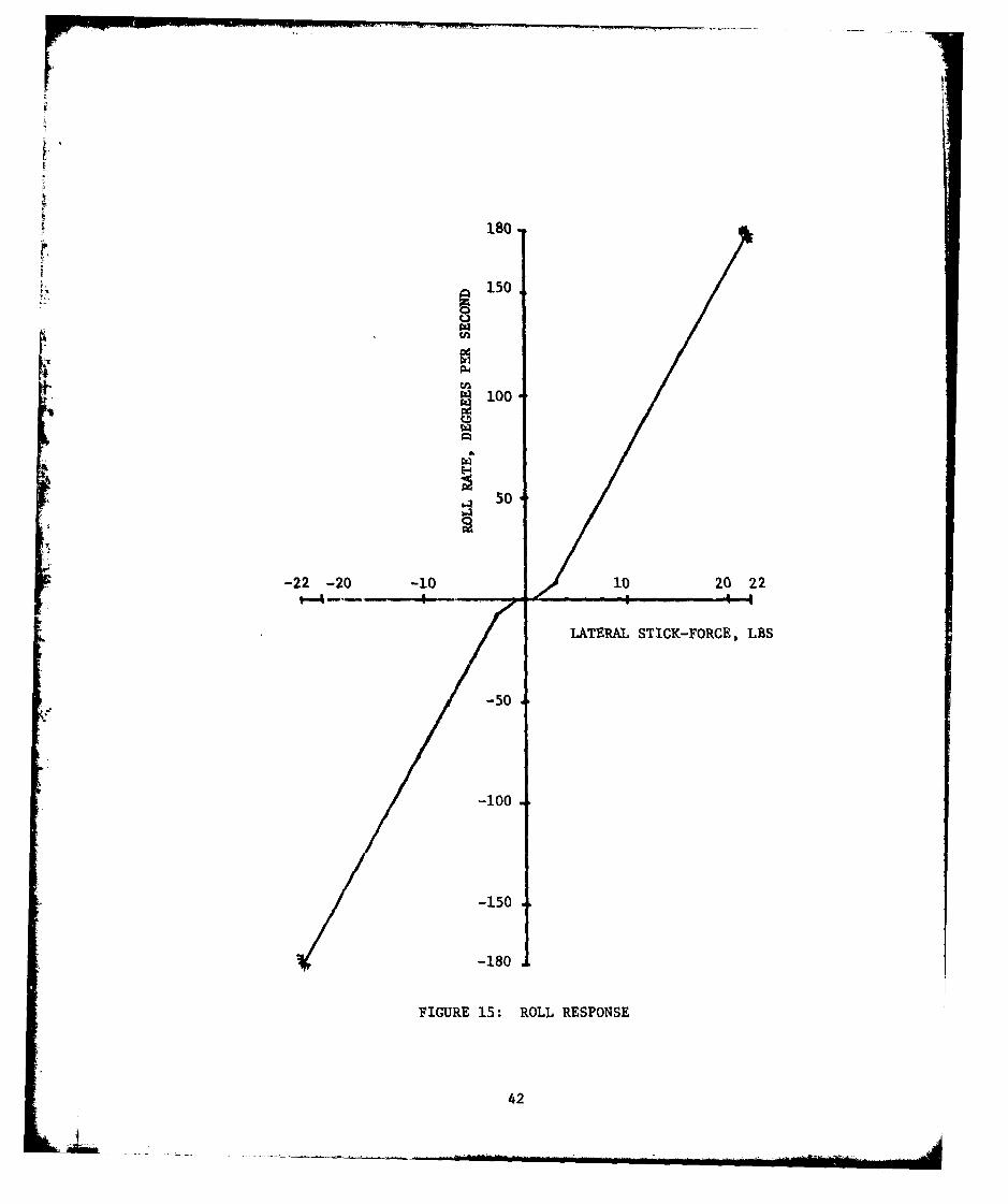
Assuming the aircraft has a maximum steady roll rate of 180 0 second,
working backwards under the constraints of 0.8 lb breakout forces and
a halving of the force/response gradient at 3 pounds stick force yields
Figure 15. The force/response gradients are approximately 3.6 degrees
per second per pound initially, and approximately 7.2 degrees per second
per pound beyond the break point.IAs discussed in Section IV-.F, a parallel trim system is suggested.
41
180
150
r~100
-22 -20 -101i0 22
SLATERAL STICK-FORCE, LBS
S-50100
-150
-180
FIGURE 15: ROLL RESPONSE
42
APPENDIX B
TECHNICAL RESULTS AND DISCUSSION FROM USAF TEST PILOT SCHOOL
LETTER REPORT - 1 July 1977 "Limited Flight Evaluation of Sidestick
Controller Force/Deflection Characteristics on Aircraft Handling
Qualities" by William M. Cima, Lieutenant, USN; Armand Jacob,
Captain, FAF; Thomas J. LeBeau, Captain, USAF; Charles M. Miller,
Captain, USAF anw Jack T. Stebe, Captain, USAF.
ABSTRACT
A limited investigation of the effect of sidestick controller
longitudinal and lateral force and deflection characteristics upon
the pilot evaluation of aircraft handling qualities in Category A
and C tasks was conducted. Twenty-three flights were flown in the
NT-33A, USAF S/N 51-4'.zO from 13 May 1977 to 3 June 1977 at the USAF
Flight Test Center, Edwards AFB, California. Data presented consistsof Cooper-Harper pilot ratings and comments on each control configur-
ation. These data can be used in specifying requirements and design
criteria for Class IV aircraft with sidestick controllers. Pilots
preferred large control stick motion with light control force gradients
for the air-to-air tracking task. Aircraft lateral-directional
characteristics detracted from the pilot's ability to evaluate lateral
control effectiveness and control harmony. The approach tracking
task did not enable the pilots to discriminate between control
configurations. Insufficient data were obtained on the landing task
to properly define the areas of good configurations.
43
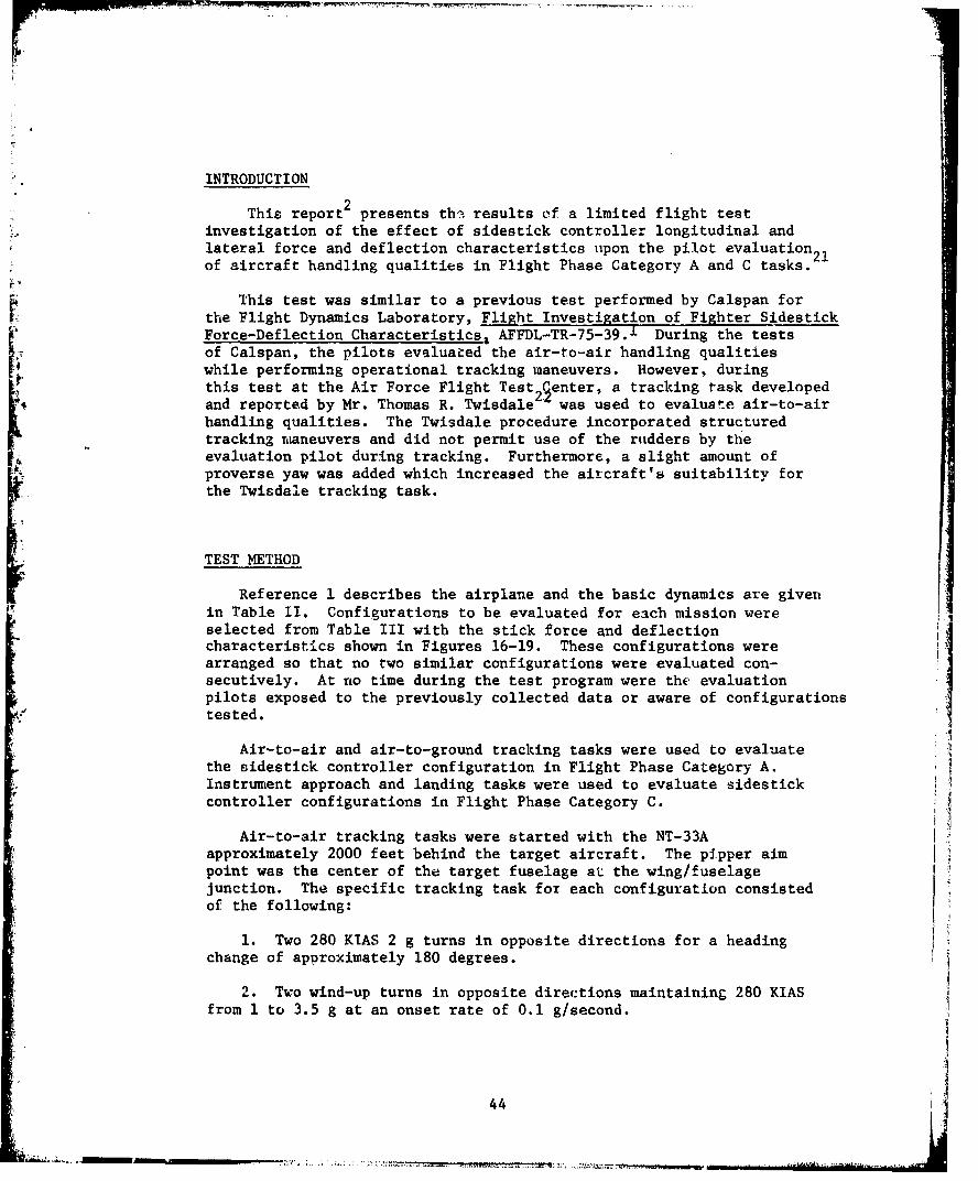
-MM q- - -- -7 -. - -
INTRODUCTION
This report2 presents th,:. results of a limited flight testinvestigation of the effect of sidestick controller longitudinal andlateral force and deflection characteristics upon the pilot evaluation21of aircraft handling qualities in Flight Phase Category A and C tasks.--
This test was similar to a previous test performed by Calspan forthe Flight Dynamics Laboratory, Flight Investigation of Fighter SidestickForce-Deflection Characteristics, AFFDL-TR-75-39. 1 During the testsof Calspan, the pilots evaluated the air-to-air handling qualitieswhile performing operational tracking maneuvers. However, duringthis test at the Air Force Flight Test 25enter, a tracking task developedand reported by Mr. Thomas R. Twisdale was used to evaluate air-to-airhandling qualities. The Twisdale procedure incorporated structuredtracking maneuvers and did not permit use of the rudders by the
4 evaluation pilot during tracking. Furthermore, a slight amount ofproverse yaw was added which increased the aitcraft's suitability forthe Twisdale tracking task.
TEST METHOD
Reference 1 describes the airplane and the basic dynamics are givenin Table II. Configurations to be evaluated for each mission wereselected from Table III with the stick force and deflectioncharacteristics shown in Figures 16-19. These configurations werearranged so that no two similar configurations were evaluated con-secutively. At no time during the test program were the evaluationpilots exposed to the previously collected data or aware of configurationstested.
Air-to-air and air-to-ground tracking tasks were used to evaluatethe sidestick controller configuration in Flight Phase Category A.Instrument approach and landing tasks were used to evaluate sidestickcontroller configurations in Flight Phase Category C.
Air-to-air tracking tasks were started with the NT-33Aapproximately 2000 feet behind the target aircraft. The pipper aimpoint was the center of the target fuselage at the wing/fuselagejunction. The specific tracking task for each configuration consistedof the following:
1. Two 280 KIAS 2 g turns in opposite directions for a headingchange of approximately 180 degrees.
2. Two wind-up turns in opposite directions maintaining 280 KIASfrom 1 to 3.5 g at an onset rate of 0.1 g/second.
44
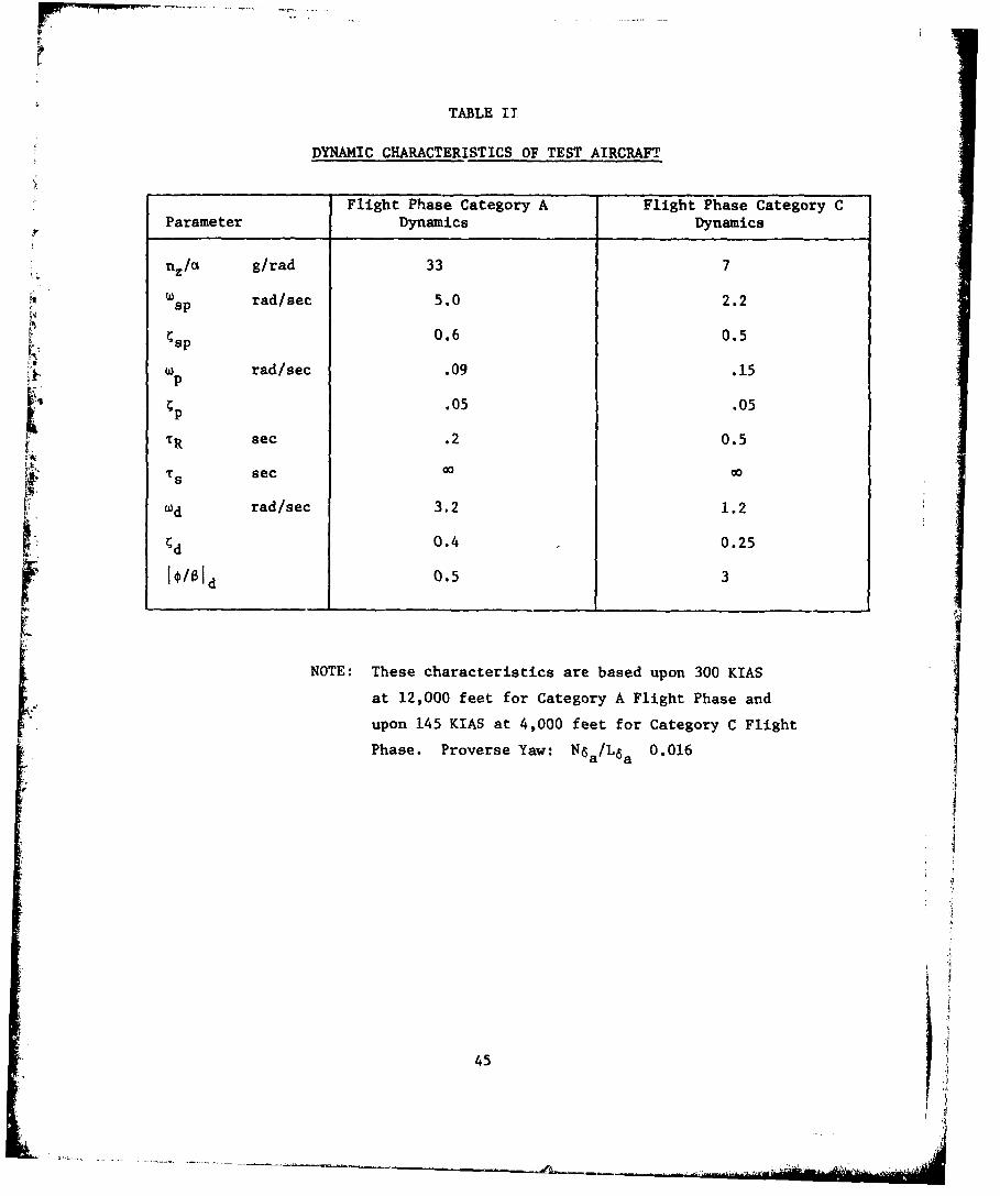
TABLE II
DYNAMIC CHARACTERISTICS OF TEST AIRCRAFT
Flight Phase Category A Flight Phase Category CParameter Dynamics Dynamics
nz/a g/rad 33 7
Csp rad/sec 5.0 2.2
0.6 0.5ýsp
w rad/sec .09 .15•. Up
.05 .05+p
TR sec .2 0.5
"i Ts sec 0o 0o
(d rad/sec 3.2 1.2
ýd 0.4 0.25
0.5 3
NOTE: These characteristics are based upon 300 KIAS
at 12,000 feet for Category A Flight Phase and
upon 145 KIAS at 4,000 feet for Category C Flight
Phase. Proverse Yaw: N6 a /L 6 a 0.016
45I
45 ,
-~-.*.,~-.- ------- * ____ ___ ___
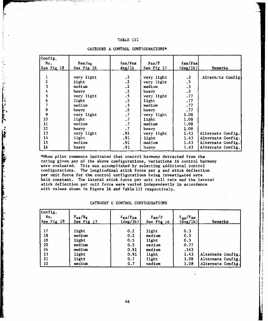
TABLE III
CATEGORY A CONTROL CONFIGURATIONS*
Config.No. Fes/nz Ses/Fes Fas/P 6as/Fas
See Fig 18 See Fig 16 deg/ib See Fig 17 (deg/ib) Remarks
1 very light .2 very light .3 Alternzte Conf-ig2 light .2 very light .33 medium .2 medium .34 heavy .2 heavy .35 very light .5 very light .776 light .5 light .777 medium .5 medium .778 heavy .5 heavy .779 very light .7 very light 1.08
10 light .7 light 1.0811 medium .7 medium 1.0812 heavy .7 heavy 1.0813 very light .91 very light 1.43 Alternate Config.14 light .91 light 1.43 Alternate Config.15 medium .91 medium 1.43 Alternate Config.16 heavy .91 heavy 1.43 Alternate Conf1g.
*When pilot comments indicated that control harmony detracted from therating given any of the above configurations, variations in control harmonywere evaluated. This was accomplished by selecting additional controlconfigurations. The longitudinal stick force per g and stick deflectionper unit force for the control configurations being investigated wereheld constant. The lateral stick force per unit roll rate and the lateralstick deflection per unit force were varied independently in accordancewith values shown in Figure 16 and Table III respectively.
CATEGORY C CONTROL CONFIGURATIONS
Config.No. Fes/Nz 6es/Fes Fas/P Sas/Fas
See Fig 19 See Fig 17 (deg/ib) See Fig i6 (deg/Ib) Remarks
17 light 0.2 light 0.3 'A
18 medium 0.2 medium 0.319 light 0.5 light 0.320 medium 0.5 medium 0.7724 medium 0.91 medium .14323 light 0.91 light 1.43 Alternate Config.21 light 0.7 light 1.08 Alternate Config.22 medium 0.7 medium 1.08 Alternate Config.
T
46
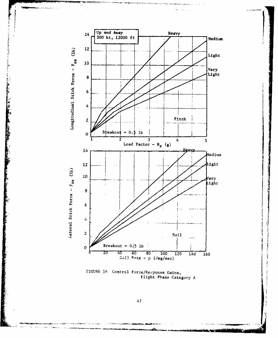
14 Up and AwayHev300 kt, 12000 ft Medium
12.......
44 4) 1*Ver
0d 4
12 3 45Load Factor- NZ (g)
'1' 1 ~ M e d i u m
12 ..Light
10 14- Very
6
W 4A
Breakout -0.15 lb20 40 60 80 100 120 140 160
'zl! Rnt - p O'eg/sec)
FIGURE 16 Control Force/Rei:ponse Gains,Flight Phase Category A
47
~~~~~'4~~........ ..... ...~M .4.4.
. ", ~44 . . .-. . .. -4 -- ---. ~ - 4
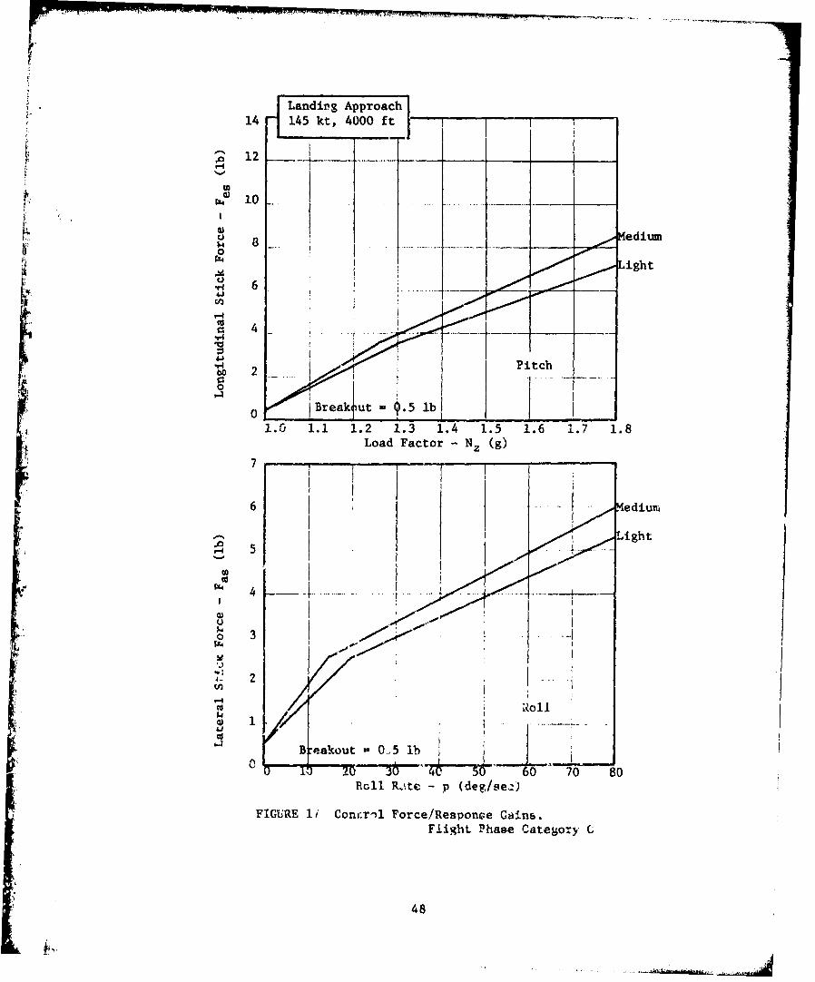
S| Landirg Appr~oach
14 145 kt, 4000 ft12 T
S10i vi
Medium0.•ight
U-H 6
4.
V4
• .,,-tPitch
0,• B reak ut - .5 lb
S1.0 1.1 1.2 1.3 1.4 1.5 1.6 1.7 1.8
Load Factor - NZ (g)
6 M edium
- Light
0 -olb
0 20 "6 go 70 80Roll R.:te -p (deg/se4-)
FIGURE 1i/ Cont'.rnl Force/Response Gains,Flight Phase Category C
48
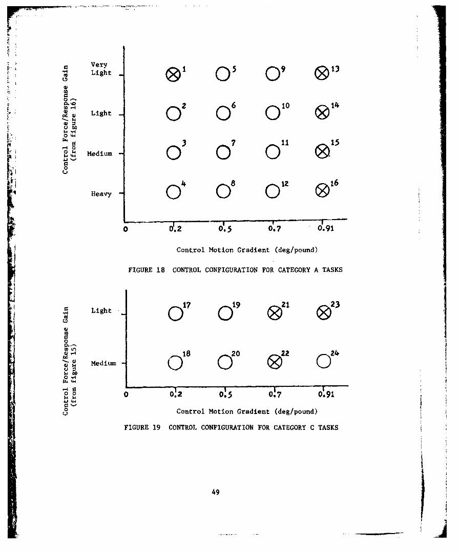
VerySLight 0Sc0 0 9
0
0O 2 6 10 14,• • Light
uao
o. '- Medium0
o r.2 0.5 0.7 0.91
FIGURE 18 CONTROL CONFIGURATION FOR CATEGORY A TASKS
0 0 0
,fi ,
0
42 u 1
" • Medium 0"0a0 v0 0 8 0
0 2 0.50.7 0.91
SControl Motion Gradient (deg/pound)
FIGURE 19 CONTROL CONFIGURATION FOR CATEGORY C TASKS
tI
-Lg
w b
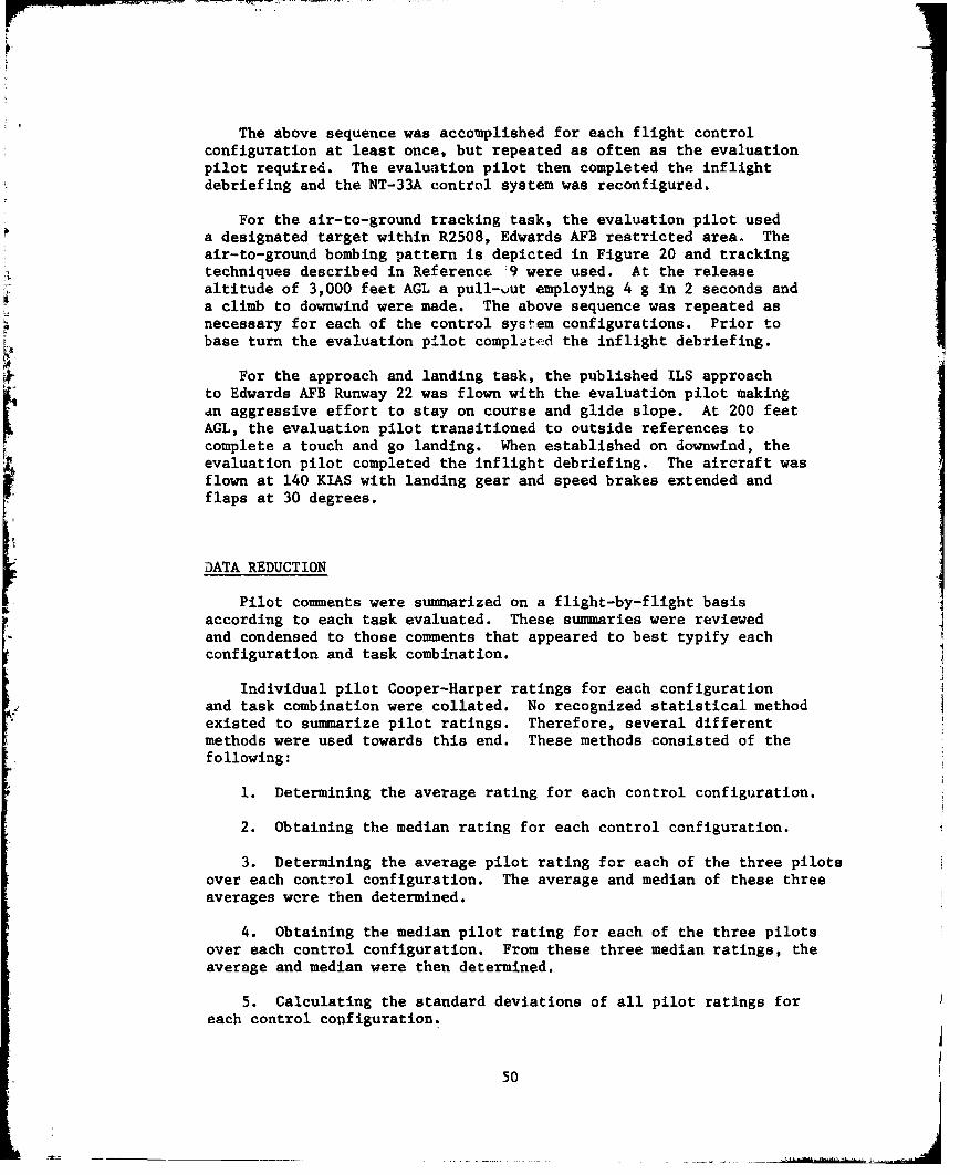
The above sequence was accomplished for each flight controlconfiguration at least once, but repeated as often as the evaluationpilot required. The evaluation pilot then completed the inflightdebriefing and the NT-33A control system was reconfigured.
For the air-to-ground tracking task, the evaluation pilot useda designated target within R2508, Edwards AFB restricted area. Theair-to-ground bombing pattern is depicted in Figure 20 and trackingtechniques described in Reference '9 were used. At the releasealtitude of 3,000 feet AGL a pull-vut employing 4 g in 2 seconds anda climb to downwind were made. The above sequence was repeated asnecessary for each of the control system configurations. Prior tobase turn the evaluation pilot completed the inflight debriefing.
For the approach and landing task, the published ILS approachto Edwards AFB Runway 22 was flown with the evaluation pilot makingan aggressive effort to stay on course and glide slope. At 200 feetAGL, the evaluation pilot transitioned to outside references tocomplete a touch and go landing. When established on downwind, the
evaluation pilot completed the inflight debriefing. The aircraft wasflown at 140 KIAS with landing gear and speed brakes extended andflaps at 30 degrees.
DATA REDUCTION
Pilot comments were summarized on a flight-by-flight basisaccording to each task evaluated. These summaries were reviewedand condensed to those comments that appeared to best typify eachconfiguration and task combination.
Individual pilot Cooper-Harper ratings for each configurationand task combination were collated. No recognized statistical methodexisted to summarize pilot ratings. Therefore, several differentmethods were used towards this end. These methods consisted of thefollowing:
1. Determining the average rating for each control configuration.
2. Obtaining the median rating for each control configuration.
3. Determining the average pilot rating for each of the three pilotsover each control configuration. The average and median of these threeaverages wore then determined.
4. Obtaining the median pilot rating for each of the three pilotsover each control configuration. From these three median ratings, theaverage and median were then determined.
5. Calculating the standard deviations of all pilot ratings foreach control configuration.
50
. . . . . . . . . ....
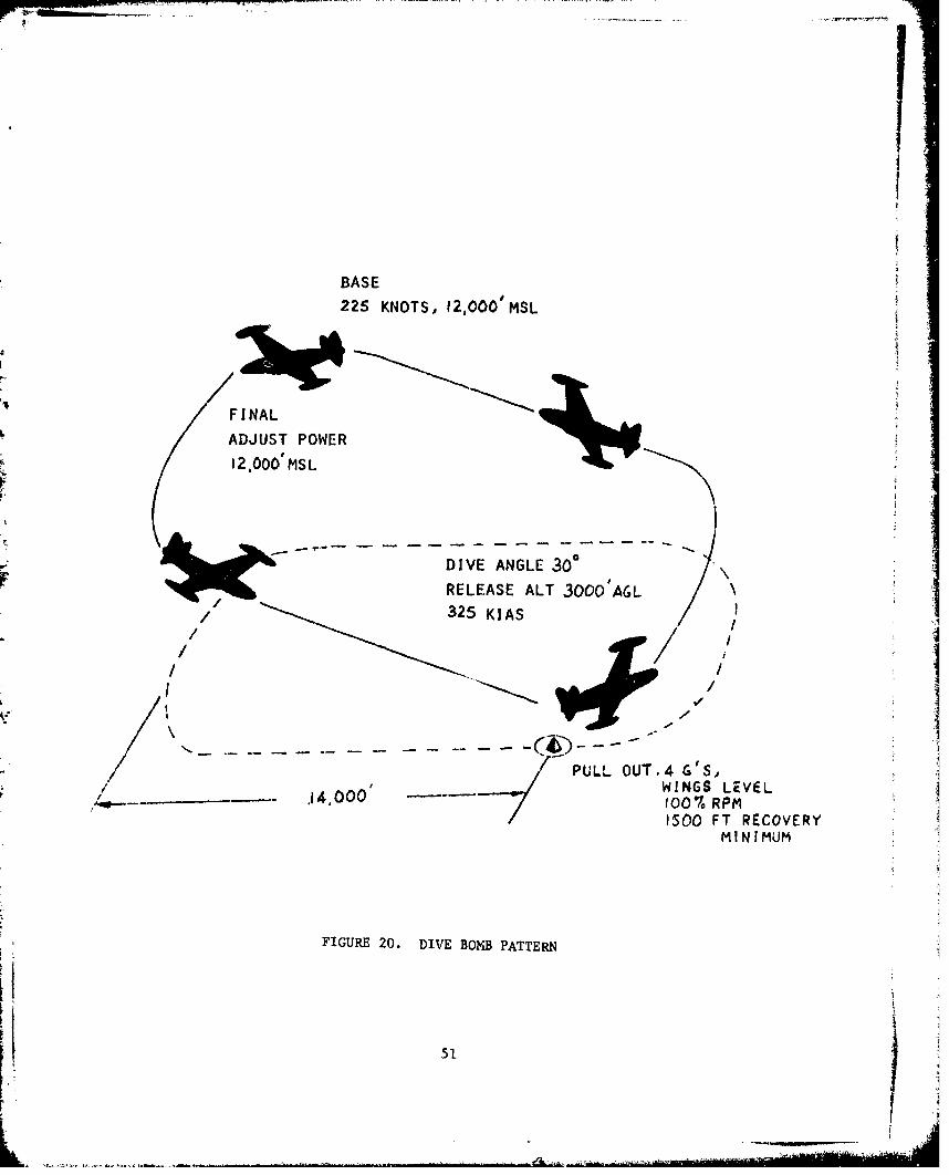
pw1
BASE
225 KNOTS, 12,000' MSL
FINAL
ADJUST POWER412.000' MS L
- ~- DIVE ANGLE 300
RELEASE ALT 3000'A6L325 KIAS/
PULL OUT.4 G '5,
______- 14.00WINGS LEVEL1500 FT RECOVERY
MINIMUM
FIGURE 20. DIVE BOMB PATTERN
51
TEST RESULTS
Data were gathered and reduced for the air-to-air, air-to-groundand approach and landing tasks. Control harmony and the effect ofbreakout force on pilot ratings were investigated for selected air-to-air control configurations. Pilot background questionnaires arepresented in Table IV.
The results of the air-to-air tracking tasks are presented inFigure 21: representative pilot comments for each control configurationare shown in Figure 22. The matrix of control configurations wasdivided into four areas based on relative performance. Although theCooper-Harper ratings were treated with a variety of statisticalreduction techniques, as shown in Figures 23 through 31, eachtechnique have essentially the same area boundaries. Figures 25 and29 show good correlation in ratings among pilots. Figure 32 shows thestandard deviation for the ratings for each configuration to beapproximately one. These data should be used in specifying requirementsand design criteria for Class IV aircraft with sidestick controllers.
In general, pilots preferred increased control stick motion withdecreased control force gradients and decreased control stick motionwith increased control force gradients. Control configurations inarea I of Figure 21 yielded the best results, both in pilot ratingsand comments. Pilots indicated that control motions were noticeablylarge but not uncomfortable. Area I configurations were on the edgeof the test matrix; thus, the extent of this area was not determined.Additional testing should be accomplished to completely define area I.
Area II configurations were found to be good , but slightly inferiorto area I configurations. Pilot comments indicated that the stickforces for configuration 4 were tiring and uncomfortable. Though theboundaries were not completely determined, these comments imply thatarea II would probably not continue with heavier force gradients.
Area IV configurations were rated the poorest. They werecharacterized by longitudinal and lateral sensitivity oz, in the caseof configuration 16, aircraft sluggishneEs.
Area II includes all of the remaining control configurations. Notethat with medium control stick motion, the control force gradientselected had essentially no effect on pilot ratings. However, pilotcomments show a trend from oversensitivity to sluggishness as thecontrol force gradient increased from very light to heavy.
The effect of breakout force on pilot ratings was investigated byincreasing the breakout force to one pound for control configurations7 and 11. Figure 33 shows that pilot ratings were worse for configuration? and essentially the same for configuration 11 as compared to ratings
52
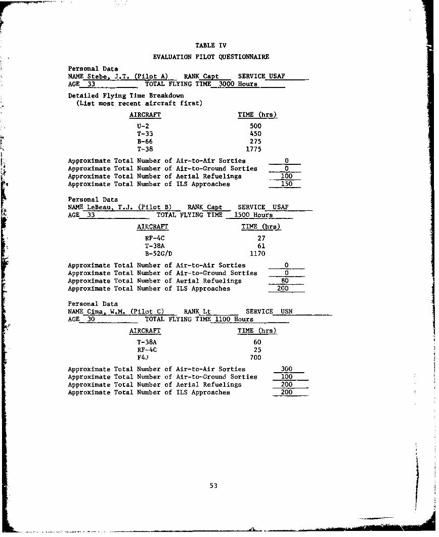
TABLE IV
EVALUATION PILOT QUESTIONNAIRE
Personal DataNAME Stebe, J.T. (Pilot A) RANK Capt SERVICE USAFAGE 33 TOTAL FLYING TIME 3000 HoursDetailed Flying Time Breakdown
(List most recent aircraft first)
AIRCRAFT TIME (hrs)
U-2 500T-33 450B-66 275T-38 1775
Approximate Total Number of Air-to-Air Sorties 0Approximate Total Number of Air-to-Ground Sorties 0Approximate Total Number of Aerial Refuelings 100Approximate Total Number of ILS Approaches 150
Personal DataNAME LeBeau, T.J. (Pilot B) RANK Capt SERVICE USAFAGE 33 TOTAL FLYING TIME 1500 Hours
AIRCRAFT TIME (hrs)
RF-4C 27T-38A 61B-52G/D 1170
Approximate Total Number of Air-to-Air Sorties 0Approximate Total Number of Air-to-Ground Sorties 0Approximate Total Number of Aerial Refuelings 80Approximate Total Number of ILS Approaches 200
Personal DataNAME Cima, W.M. (Pilot C) RANK Lt SERVICE USNAGE 30 TOTAL FLYING TIME 1100 Hours
AIRCRAFT TIME (hrs)
T-38A 60RF-4C 25F4J 700
Approximate Total Number of Air-to-Air Sorties 300Approximate Total Number of Air-to-Ground Sorties 100Approximate Total Number of Aerial Refuelings 200Approximate Total Number of ILS Approaches 200
53
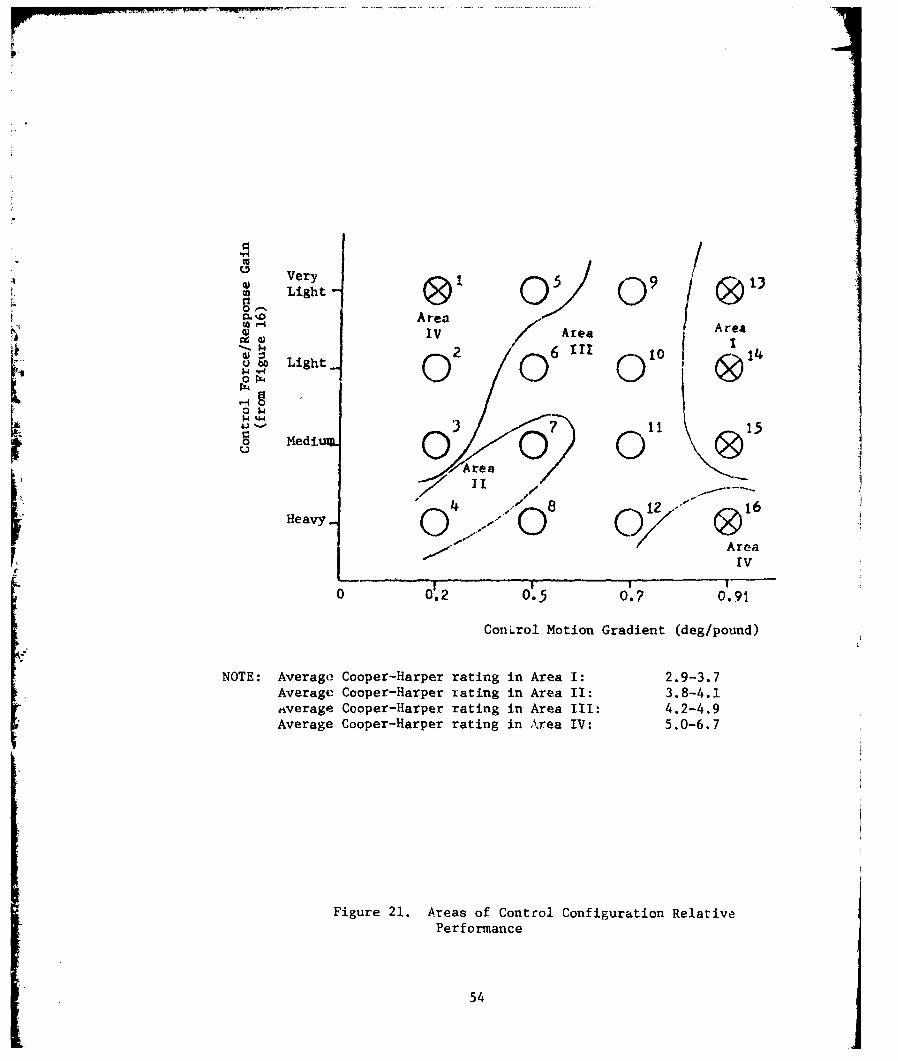
0 1 /'U
Very , ' 5 13Light -191 01 01 0& 1
MID AreaIV Area I
4 r Light 2 6 00 14
LL4 rZ4 000(
01.2 3 -7115
Mediu 0 0rAre
.I "
Heavy - Qregrv
0 0'.2 0'-5 0. ?o 1.91
ConLrol Motion Gradient (deg/pound)
NOTE: Average Cooper-Harper rating in Area I: 2.9-3.7
Average Cooper-Harper rating in Area II: 3.8-4.1average Cooper-Harper rating in Area III: 4.2-4.9Average Cooper-Harper rating in Area IV: 5.0-6.7
Figure 21. Areas of Control Configuration Relative
Performance
54
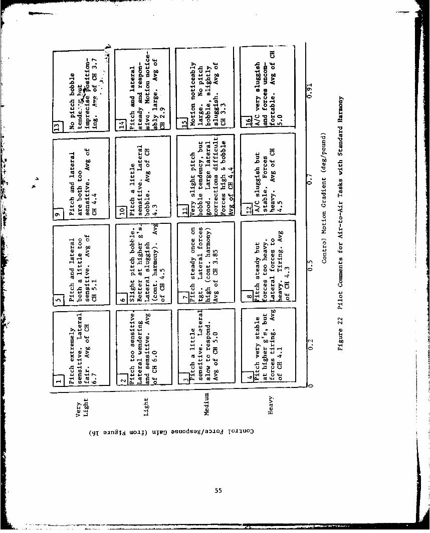
it's ~4.41 -H0 4-4 .
9 cn*. H ".10
41 4 41
.41 'o 4. 4 OI-a 0-H oof0 o o r.0 r4 410Ht
x 0) 0 z w0C
.0O L.4 u 0dQ> * 0: 01
1. j 0 > *d Hb ' w A
P~0 *0 4(AL
44) 0~001 U 041 4 410
* . Oa)4 4J~~.. .4-4 :3oAI0 bo "0 4OHH 0d4 0 H)1+41 A r- . Lg4 a$0-I0 413 41 VW b * wO~ .9I 4
>.1 0.~ A 4) 0O 5 44c H O 4 41 40. co
0 6 t .4 w.CA 44 M 0- -OH *r ; 4. -H O. H 0
uOH m mA o% .0 0 w0)U( t nýW 000 00. 0 > .
0ýtl G) E9ý .8 H 0 ~ W 's-4 J
>o 0o
ca0 f.0 14 A 0 41 411-4-10 0~O bo0 -Li
OH 4 .0 bO r-4 0.094Hdr 44.1.o , 'PON~ '0 *u ~4$4 0Ar-4 O 004. u0 H 5 :
0 .-4 H P. 0 4 ; 4 0 H "4-r4 H 0O 4J 0) .0Wj toU
w 41 LA b04.J U - 4.J-4 4.3oH .O H 0) k4-1 j-Hb H "H O 0 4 -&
HOI I 0Z)41 *H' b41, 6 J11-4 0bO C U4- r00 *H>
LA. 0 IN4
* 4-1 00 a)-1.00 .OH 4JH 0 4) t4 ,Q-4-boo
00C T11.4 00 0 41-40
H 0 * H0 WV)b 4 11b
4.3 4.1 0 ., w
O ;H 0 Hd-
(91C 0ISdwI) ujH 03~S1a~O 44 0) m
p m uw u u55
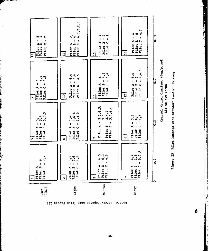
i-
Ln T1C4 C4'*I I
4. 1. 41)Q. 41 414 00 0000o 0 00 HHr-*I r- -4 H V~4-H -H ~0 P4 PW
HH -H~4~ JH pH49
A4 A,44 0 FW 4 hnhoi0
'00
t 40
000410 0H r.4 r-4 ,4.H,-I4 U$4F-4 41)0 a~ 0 4HrI- - Hv AV
H vi 4 P4 04 P r
4 0 14'04. cc
ar P,
~o,4n n a an $4LI
. a a 4.en) e 0 4'0nC '4 an an an an u aa
iii '1 41 4J ill IJ0000 a a a4 a4 '0'D r-i r-4 H
HI IH IIH -r4 04 AIN4 4PLn P4 4 4 A4 A - -4
4.)ý- 4.) i fClC4
560
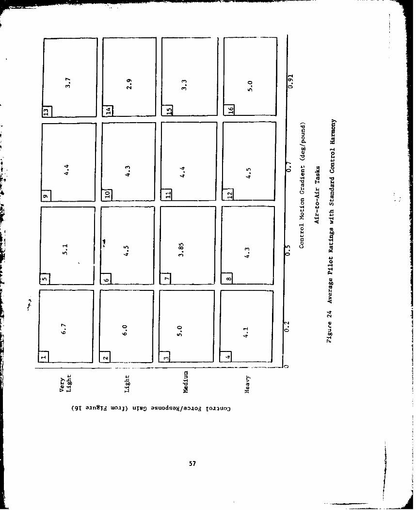
CD
Cl * 0
-4
0
0 I A,
0
C.))
I91 aiST *1J ~gasosHa4O OI
N 057

LA 0% --t In H
LA-#C'T C'-4C~ h I
J~)4.J9q 00
41 4.)4j. 41 4 141 0 00 r14 4.)0 0 00 0 0
144 V4 rHv-l 1--4 HHH -rH H P4P W0-H HHH P4 P. P4 U
-1H ýP4~l P" FN
00
LAn LAL 14, -
m000c 0L 4 5
Ai41414 4 0 0 o ca'
Pr H4 0uo C)
aN =W4N 1LA4- 0~ H~~L0L
0 P4
I".~~~~ý LA0.t-UU- A .
0004 000 000
0 H4j 4j j 0 0I0AL 0AL 0 000 -
4 "4CiL N- - 4- jr4-HA4L *rlP4P r
III I i I I II 0>
441
C) 0 0
944
58
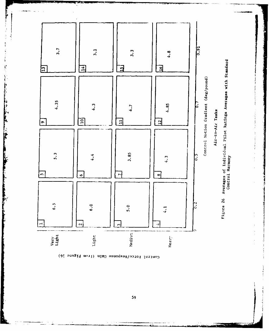
-to
60
41 0
00
0n 0
-4 ý4.
'4 0
0 4 0
Ct' beU-
> .44
(91 inS asu dsa /a:.joq loi uo0
594
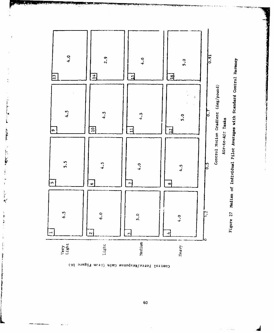
r rx -01 -
0 0 041
V 0
-V 606i
ac
H r
5.411.4
0 0
Id, 0
ai-
600
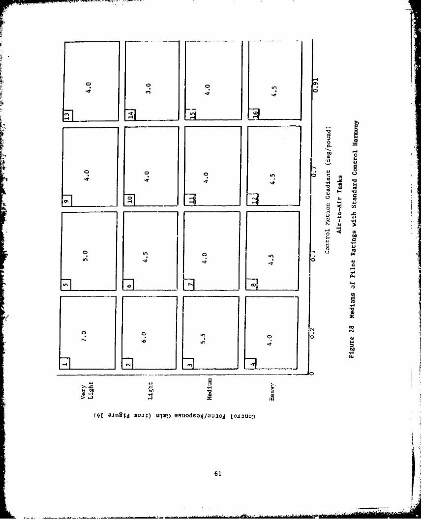
.4M
F, '-?4 No,
t 01
-4
100
W .)
0
V74
co
Jow o V
w~ "A.-
>-
OT- aiSNmi)UN)audot/ao o:u:
IA 61
IIII&P-4
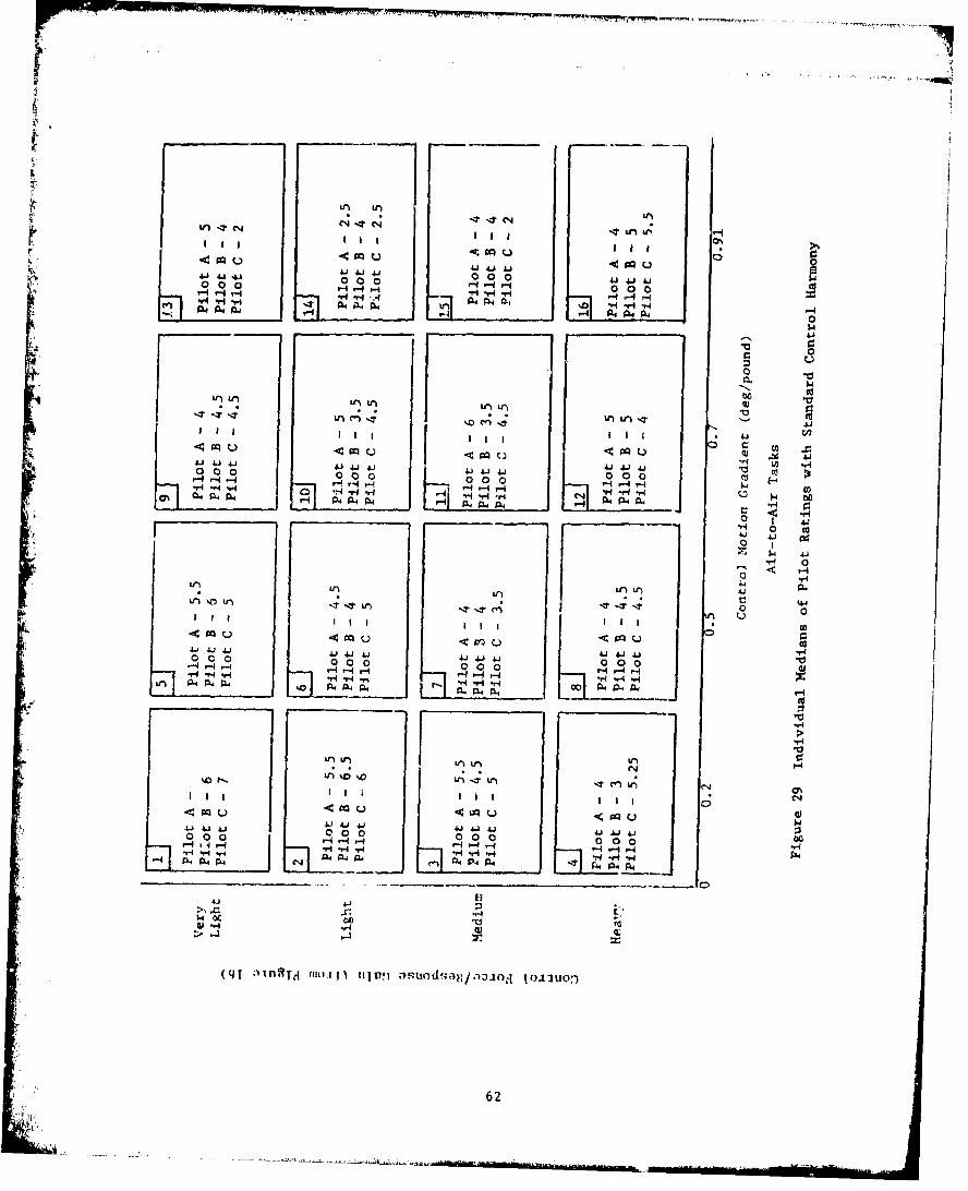
u. I u~
41 0 0 00 0 4 .o0 J4 j 14jt 0 4ý
A4 P0
a-'u.Ln in1
Uktr
0I 0 0
A44 4.0% 4
000$ 4.414.
ILf Hj PL.,N -r - r0 0c
ugo
0 0 0 4)4j 4 4.) . 0 00j4j 40H 00 ov4 0 0o0J
P44 %r4F.o Pý 91 4 n
N '-4
0 0 0 o.0 0 0 0 0 0 0-0
(qtJ4. a)4T qod-j/'oaj liu
624.44 -

'-44
0 0 0
* 0 0
60
10 'A
C4.4
4 .-4U, ~0 0
44.004 41 4 H
00-
*0
toLA~~$ 0 ro*a
* * 0
.00
OJ~4 .4
@P a
(91 ainSid UIOaJ) ujug auodsaH/a.ooa toI~uo:,
63
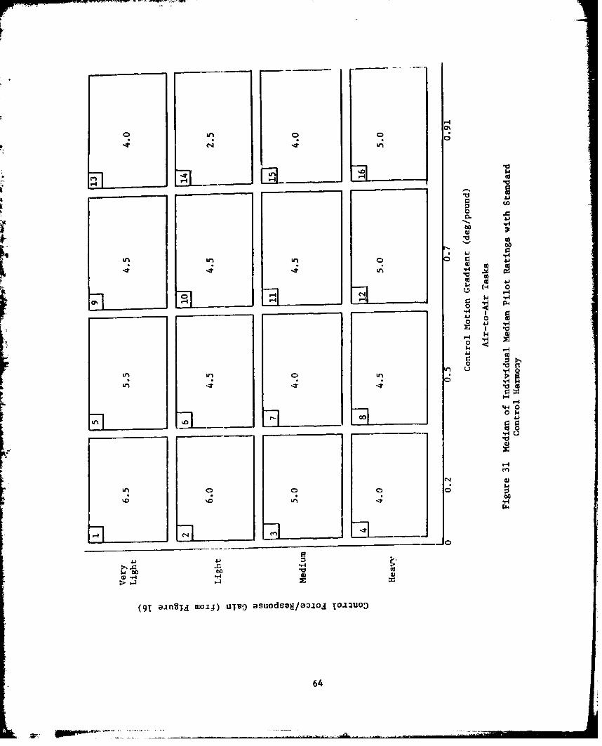
h,4 C'I -t
'h-, C___ _ -
roll 0
14.
00
a44 00
00 w ~
o ln~ 'd 0
1.4
LAb 0 0 1'C
64Z
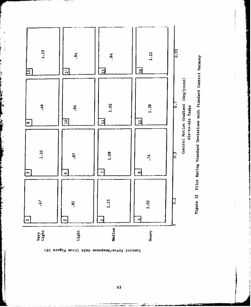
N 0%
H 0 4
00
0)
to
*0
-*4 0%0U
0 '-4
0N I
____ ____ ___0 0
4jI 41
600
1-4J
OT aig% moil oTDa~daj3o OI
65U
r-.00LA
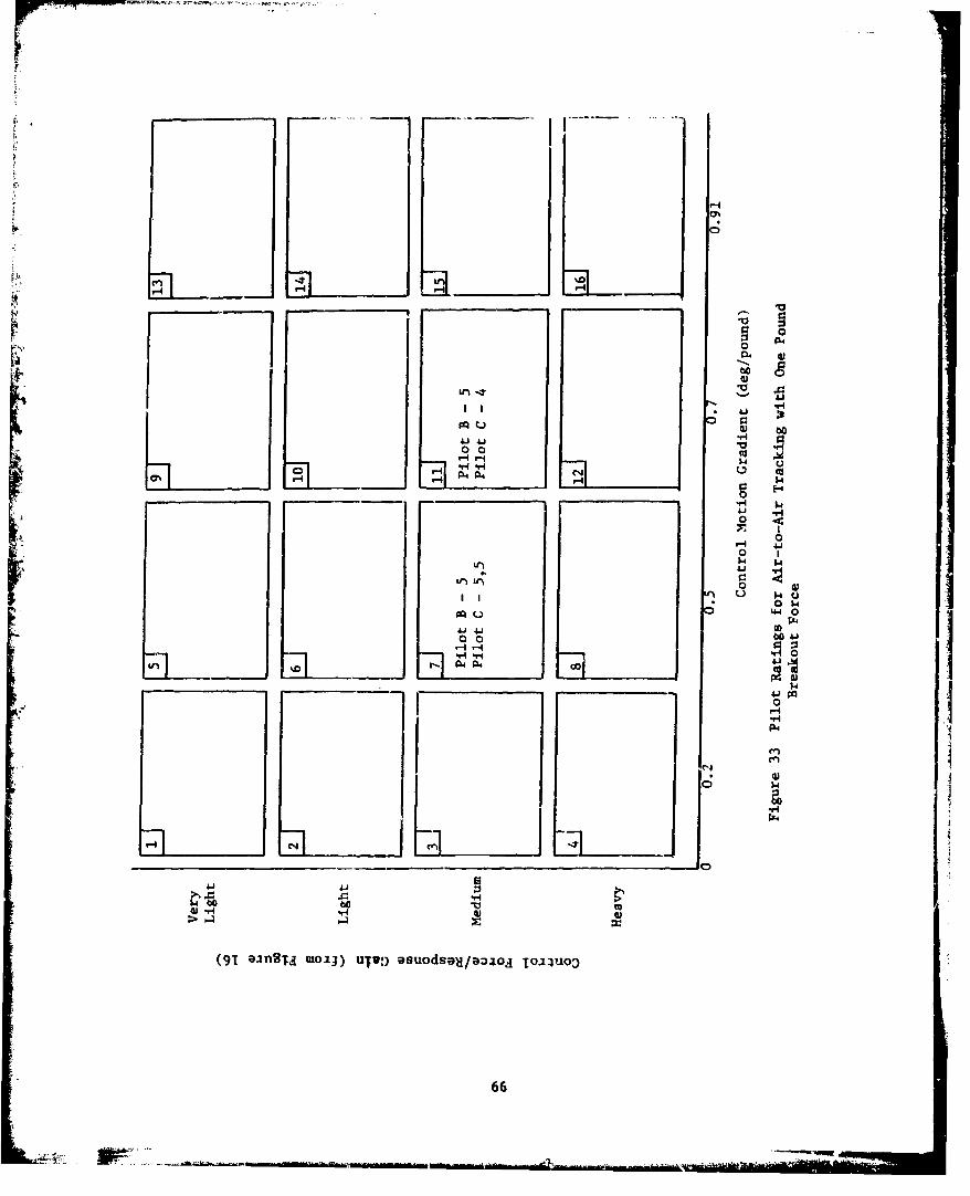
* 0
-- ~0
I, H
pq u00
41 41 9
0 0 V~ V4-4- -4-4 w
H H HHw
_ _ _ _ _ _ _ _ _ _0 E-4
0 0
0
0 $4
4.4.t0
"-.41 0n
PO
P4.Uen
('4)
H ('H
4 .1 -4.
66

for 1/2 pound breakout force. Pilot comments in Figure 34 show anincrease in pitch sensitivity with increased breakout force.
Control harmony was investigated for several control configurationswhere pilot comments indicated a lack of harmony. Lateral foices wereincreased or decreased one gradient increment for a given longitudinalforce gradient. Figures 35 and 37 show that the change in lateralforces resulted in essentially no change in pilot ratings. Pilotcomments in Figures 36 and 38 show that increasing or decreasing thelateral force gradient generally resulted in increased sensitivityalong the axis with the "lighter feel". Thus the original controlforce harmony was optimal. However, changes in control motion harmonywere not investigated. Additional control harmony testing should beaccomplished.
The aircraft lateral-directional characteristics selected forthis evaluation were not well suited for the Twisdale air-to-airtracking task. Sharp lateral inputs resulted in annoying lowfrequency directional oscillations for all control configurations.This deficiency detracted from the pilat's ability to evaluate lateralcontrol effectiveness and control harmony.
A minimum of one flight per pilot was necessary to adapt to theTwisdale task and the aircraft dynamics. Gunsight camera film wasuseful during this phase for aiding pilots in qualitatively evaluatingconfigurations and exchanging ideas on adequate versus desired aircraft
performance.
Gunsight camera films from six randomly selected flights were readIand reduced to provide pipper position error. Plots resulting fromthree control configurations are presented in Figures 39 through 41.The tracking error did not correlate completely with pilot ratingssince the amount of pilot compensation was not measuxed. Hence, theseplots were not considered useful for this evaluation.
Evaluation of the air-to-air tracking task was considered primaryand a target aircraft was available for each test sortie. This limitedthe number of air-to-ground and approach and landing tasks that could beaccomplished. Only 12 pilot ratings, shown in Figure 42 were obtainedfor the air-to-ground tracking task. This amount of data wasinsufficient to present conclusions on the control configurations.
Approach and landing data are presented in Figures 43, 44 and 45.Pilot comments and ratings indicated that approach and landing shouldbe evaluated as two separate tasks. Further, the approach trackingtask did not enable the pilots to finely discriminate between controlconfigurations. Though insufficient data were obtained to presentconclusions, nearly all control configurations seemed to accomplishthe approach tracking task equally well. The landing task enabledpilots to discriminate more easily between control configurations.JAdditional testing should be accomplished to optimize the controlconfigurations for the landing task.
67

-4
-t A '.0
1-0 To
0. )4)4
4))
H 4.1
0 )41- 4) 4)
co tw tj -4
0
U 4 7-4 4.1f ) *H 0 "I
*-o h 4-1 -4w4.1w~~ 0 Y.i
0
N 0n
raz
xg_-_

r .41
00
w
414$
t0 0
41 4. 04.14J4 4.1 4. 1 4.a) *0000 00
.
r q%- r-4 .. i - r4-H~~~r -r r r 4r
41-Wou
P '4
Lt)o
00
694
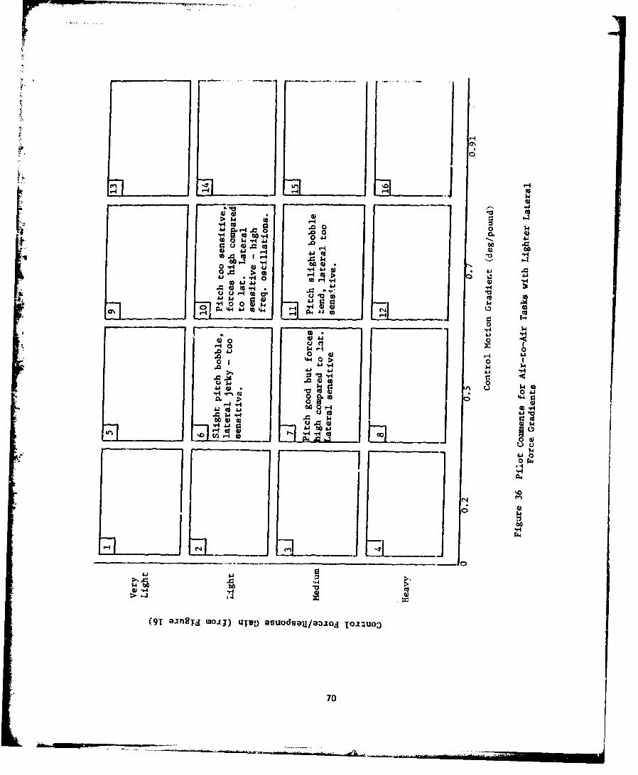
C)
400
14 to -
41 41~I4CC14600 4e
0 > toto 4J1
.G 41
0 wrA
w *100 00
4-1 41
0j0- 4A
(91 in8;.j IoIJ)w~u ~suds~U~,io To4.uo
to 41 00 m70
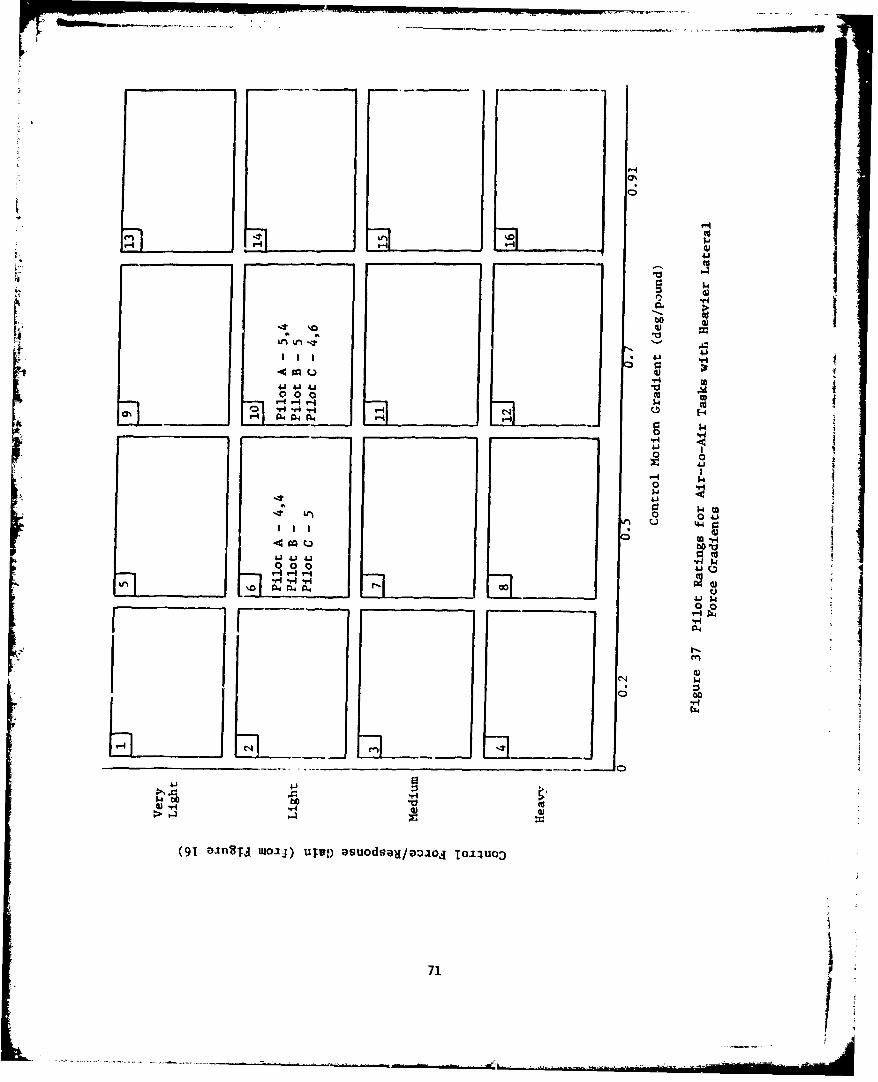
0'
00
V. -4 P-4 4-4 I.
P4 04 6
00
0~ 0
0 0 4
4,-4
V440 0 0
411't. 4 r4 4-41-
v4.
0~i4
711
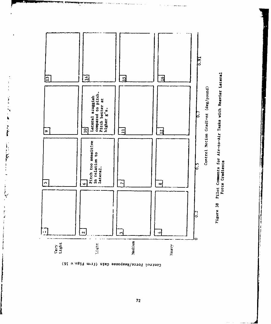
0--0'>
00
1 414
0~u 04
0
0 09
0. 0
00 0
-4 . 4 .1 - CO
1-4 w0.0k
V) A.O 0U .
4.1 ~0 0I fs
0 00
r4'
0 'I)
4. 1 O 0
(914 a-nT ".94vvaudsHojd OIO
UH72
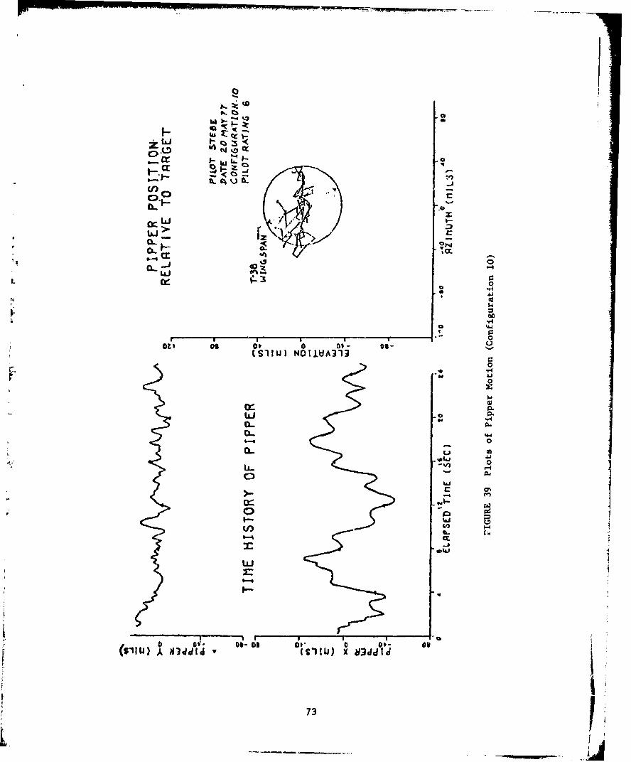
C) :S
cr 50
C4.,
CL -"CL
o 05.F4
44
Oil 08 at 0 oi- as-(SIILU) NOIDIIA313r. 0
0
0~0
0~
IAJ
0VIJ -0dclo~
I- S73
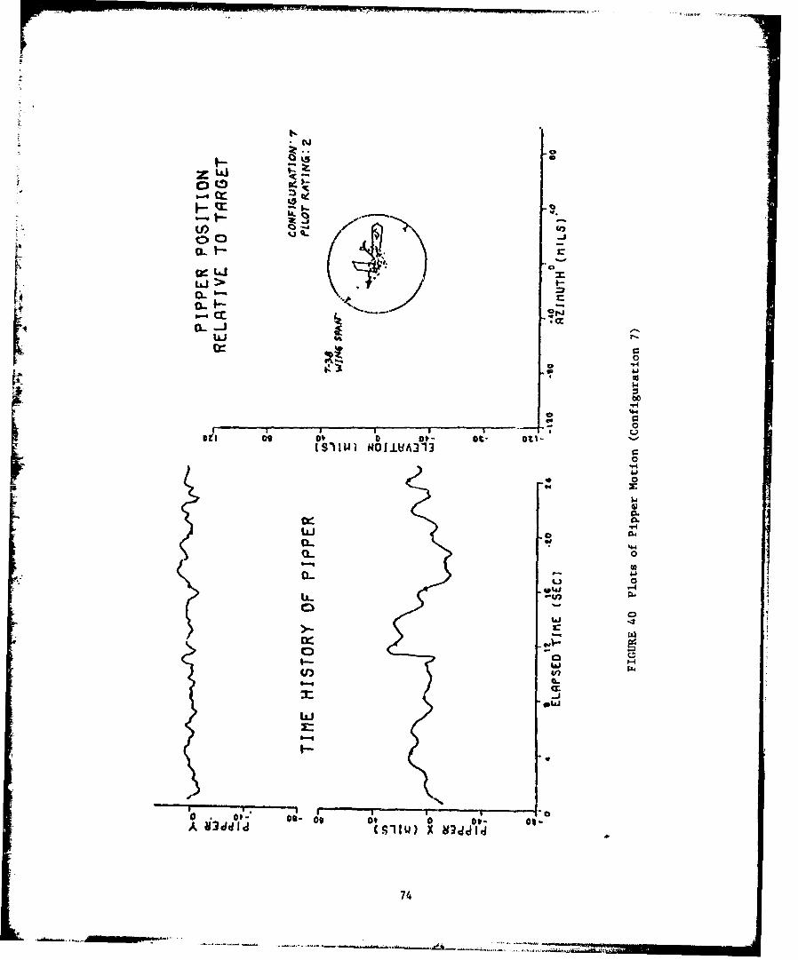
cl-N
cl.5
Ls.I
0Y44
0 4-0
cr-iLLJ .
Q.. 0
0- 0
-UJ
o o t- Do- 00 ov 0 fp - OI*A x3I~ (SII) jiJ
74
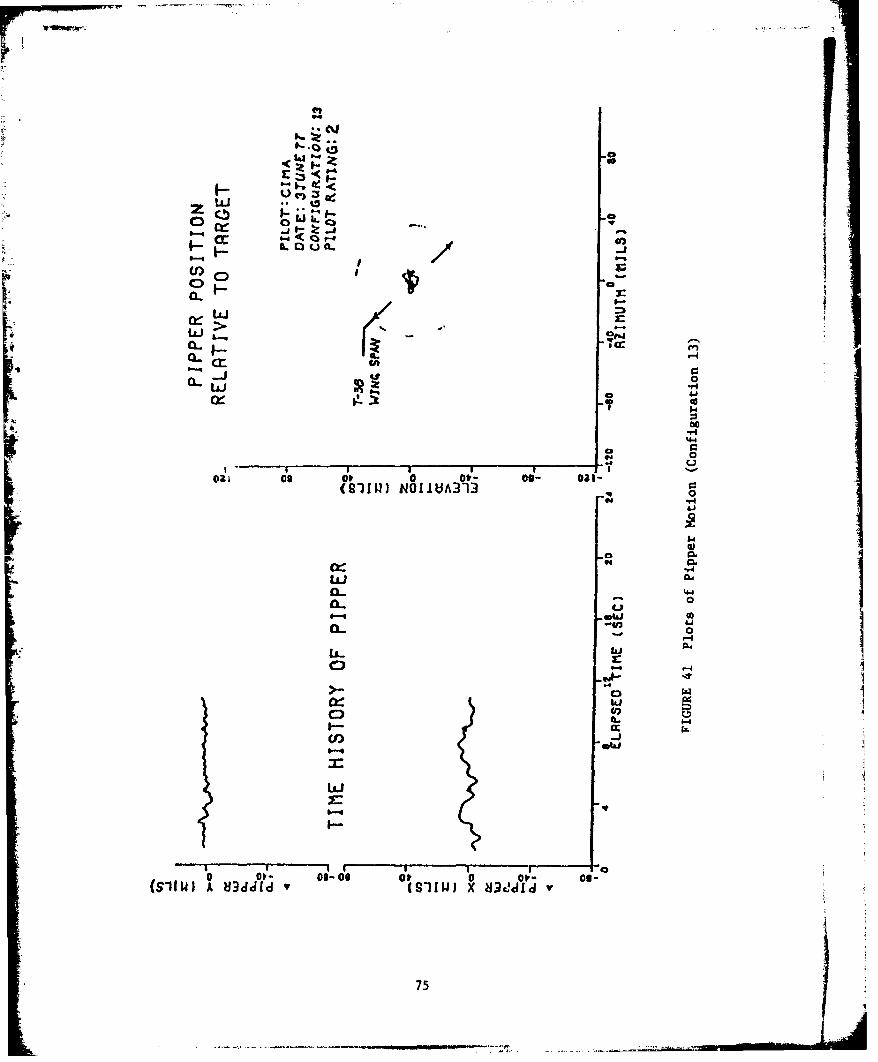
9,.4;
cc:
L a1ic
CL cc
cr-
-1 -40 - c T00
0
*1r4
0'4 0
0- 0
- 0
C)0
C)0
o 00 o-00 0 p 0 01- 09-(sg;A mildJ~ (SI!UJ )C MiXI V1
75

PQ, wI 0 V
0 00 000 oU
4 T-1 P-1 rEI r4- H -H V4 -H
N P4 P4
0.
E1-4
0% 000 (UP4 P4 N4
10
0
044 P4-4h-h, d 6 CL4 0C
000 00
-4-4 4 r~0 4
O4 4 ~ 4040IIp004u
0 0 0
CN4 -4-4A4 P4 04 P
0) 0)
(91 ainS..j UIo.I) uJu9 asuods;)H/azuol TOJI~UD
76
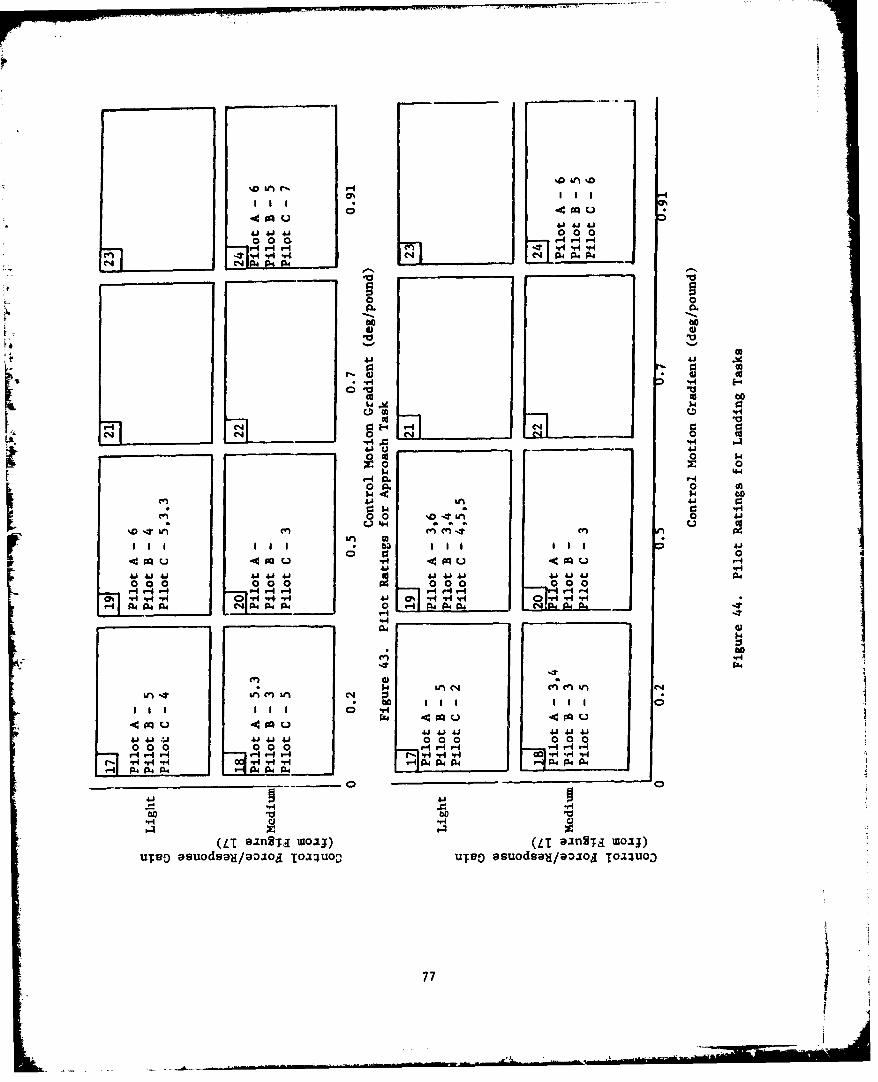
00IL64 u41 414
0..0
000
o VHS
co- a w
££0 0 0
m ~14 6
0 0 w 4J
Ql 4.4
H ~ ~ .0 0__1_ 41 41A
V-4 r 0 0 0 0 0 0 0 0 4 -4 -. ,im ý4 -,-641
C4
$4 iAn 4 en CV)I N
r4 4
41 41 41 4144A44.1 0 00 I 0000 00 0 00 r4 -4H r- I - -
r-4 V-4 6-i r4HH -1 V -H H Ir 4 4H~ -H r'V 4
.1 ri -4 N 04 P4NPjOhr, P4 040 P40.0.
414
(UT siS. uoio) (LT aangTa MiOM;uTvD asuodsou/801oi TOA~uo- ulgo asuodsa-a/901oj TI13W
77

W m-
0~
ob
0011
l--r4
V4 0
0r 004
0 -ri
0 00 4
41 410- 4 -H.- 0
0 ~ ~ P -H C)0(UE5 14
UT99o4*a9aa ol o
78 140
The pilot ratings and comments presented in this report were obtainedusing the specific tasks described in the Test Method. section. OtherCategory A and C tasks, such as gross maneuvering or formation flying,could result in different ratings and commaents for the same controlconfigurations. Additional testing should be conducted to determine theapplicability of this test data to Category A and C tasks of broader scope.
CONCLUSIONS AND RECOMMENDATIONS
The effect of sidestick longitudinal and lateral force and deflectioncharacteristics upon the pilot rating of aircraft handling qualities inFlight Phase Categories A and C was investigated. For the air-to-air task,
4 pilots preferred large control stick motion with light control forcegradients. Aircraft lateral-directional characteristics detracted from
the pilot's ability to evaluate lateral control effectiveness and controlharmony. Increasing the breakout force from 1/2 to 1 pound increasedii pitch senaitivity. The approach tracking task d~id not enable the pilotsto finely discriminate between control configurations.
Pilot ratings for the air-to-air phase correlated well. between pilotsand exhibited a standard deviation of approximately one for each controlconfiguration.
1. These data should be used in specifying requirements and designcriteria for Class IV aircraft, with sidestick controllers.
Configurations with the best ratings involved large stick motion andwere on the edge of the test matrix; thus, the extent of this area was notdetermined.
2. Additional testing should be accomplished to completely define thearea of best ratings.
The control harmony investigation was incomplete in that control motionharmon- was not evaluated.I;3. Additional control harmony testing should be accomplished.
Insufficient data were obtained for Category C tracking tasks to presentconclusions.
4. Additional testing should be accomplished to optimize the controlconfiguration for the landing task.
Other Category A and C tasks, such as gross maneuvering or formationflying, could result in different ratings and comments for the same controlconfigurations.
5. Additional testing should be coi.diucted to determine the applicabilityof this test data to Category A and C tasks of broader scope.
79

APPENDI't C
TECHNICAL RESULTS AND DISCUSSION FROM USAF TEST PILOT SCHOOL
LETTER REPORT - 9 December 1977 "Limited Flight Evaluation of the
Effect of Sidestick Force/Deflection Characteristics on Aircraft
Handling Qualities" by Vernon P. Saxon, Captain, USAF; Edward L. Daniel,
Captain, USAF; Cecil D. Haas, Captain, USAF; David G. LaBarge,
Captain, USAF; Jerry D. Pfleeger, Captain, USAF; Vernon S. Ritchey,
Captain, USAF and Guy C. Thiel, Captain, USAF.
ABSTRACT
A limited investigation was conducted to determine the impact
of varying sidestick force and deflection gradients on pilot ratings
of aircraft handling qualities. The test aircraft, AFFDL's variable
stability NT-33A, was configured with the aircraft dynamic characteristics
of a high performance fighter similar to an F-16. The region of sidestick
force and deflection characteristics which produced acceptable handling
qualities was defined for the tasks of formation, air-to-air fine tracking,
-gross acquisition, and landings. A near optimum control configuration was
identified for the aircraft and control system dynamics tested. Although
initially planned, quantitative tracking data and control harmony
investigations were not accomplished due to limited area sorties. The
data presented are in the form of pilot commentary supplemenited by Cooper-
Harper ratings. These data can be used to further expand the data base
on sidestick control configurations generated in previous evaluations of
this type. Data, target support, practice and calibratior flights totalling
48 sorties and 65 flying hours were flown at the Air Force FILight Test
Center, Edwards AFB, California from 26 October to 25 November 1977.
80
S. . .. . . . .. . . . . ..... . ..- ... . . . . .. -• • 1 T

TEST OBJECTIVES
The overall test objectives were to investigate the influence ofsidestick response/force gains and deflection/force gradients on•lot evaluation of aircraft handling qualities in formation flying,gross acquisition, fine tracking and landing tasks.
The specific test objectives were:
1. To examine the impact of varying sidestick characteristicsupon pilot evaluations of aircraft handling qualities. Sidestickcharacteristics were changed by varying the normal acceleration perunit longitudinal sidestick force (Nz/Fes) and longitudinal sidestickdeflection per unit force ( 6es/Fes) along with roll rate per unitlateral force (P/Fas) and lateral sidestick deflection per unit lateralforce (Gas/Fas) for selected Category A and C phase flight tasks.
2. Quantitative verification of task performance and correlationof pilot performance with pilot ratings was to be obtained throughsupportive data of tracking accuracy for air-to-air tracking tasks.
The secondary test objective was to obtain pilot evaluation ofaircraft handling qualities with variations in control harmony.
TEST CONFIGURATIONS
The NT-33 variable stability control system was configured tosimulate the airfrazu dynamics of a "good" airplane as shown inTable V. During the 3valuation, the elevator and aileron controlforce gradients (G's/JL,, and Roll Rate/Lb) and sidestick deflectiongradients (Degrees/Lt) were varied to obtain the various testconfigurations as shown in Figure 46. The breakout force was 0.5 Lband the force command was conditioned by a pre-filter for both axes.The pre-filters were simple first order lags with break frequenciesat 8 radian/sec for air-to-air tasks, and 4 radian/sec for landingtasks. To maintain constant roll dynamics, it was necessary to reduceroll damping and aileron ccntrol gain as fuel was depleted. Controlsystem potentiometer settings were computed for 600, 500, 400 and 300"gallons of fuel remaining, and the settings for the nearest fuelquantity were used.
Prior to the first data flight, a calibration sortie was flown tode2termine potentio,-eter settings required to obtain the desired forceand deflection gradients. At the end of the evaluation, anothercalibration flight was flown to verify the gradients. Slight changesin the gradients were observed between the two calibration flights;however, these changes should not affect the results of the tests.The results of both calibration flights are shown in Tables Vi and VII.
81
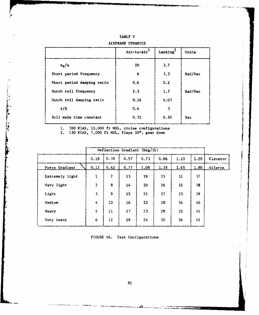
. ...... . .... .
TABLE V
AIRFRAME DYNAMICS
Air-to-air 1 Landing2 Units
nz/a 20 3.7
Short period frequency 6 3.3 Rad/Sec
Short period damping ratio 0.6 0.2
Dutch roll frequency 2.3 1.7 Rad/Sec
Dutch roll damping ratio 0.16 0.07
"0.4 3 iRoll mode time constant 0.35 0.50 Sec
1. 300 KIAS, 15,000 ft MSL, cruise configurations
S2. 130 KIAS, 7,000 ft MSL, flaps 300, gear down
Deflection Gradient (Deg/lb)
3 0.18 0.38 0.57 0.73 0.96 1.10 1.20 Elevator
Force Gradient 0.12 0.42 0.77 1.09 1.35 1.65 1.80 Aileron JExtremely light 1 7 13 19 25 31 37 JVery light 2 8 14 20 26 32 38
Light 3 9 15 21 27 33 39
Medium 4 10 16 22 28 34 40
Heavy 5 11 17 23 29 35 41
Very heavy 6 12 18 24 30 36 42
FIGURE 46. Test Configurations
82
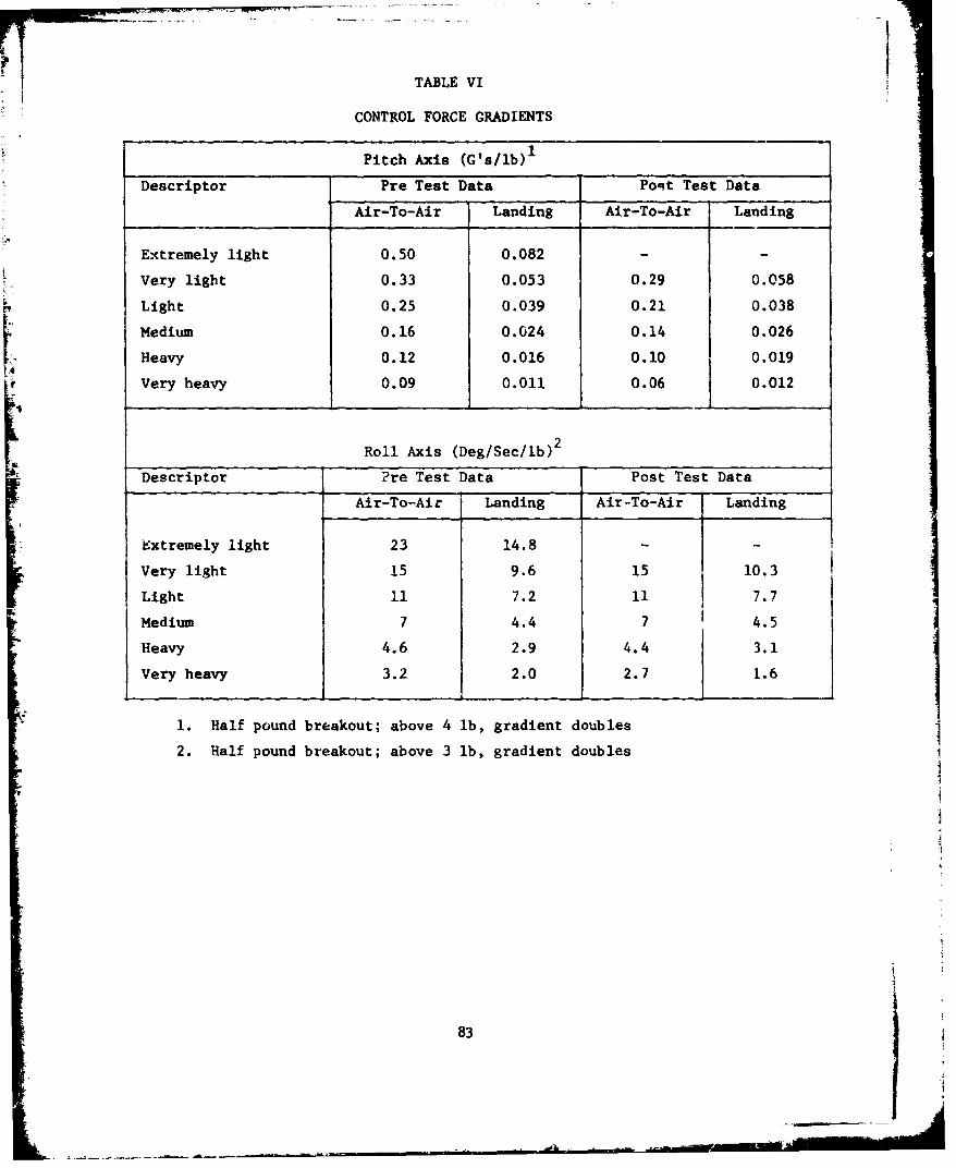
- F'•• •• ,•• •, . . -. ... ..
VTABLE VI
CONTROL FORCE GRADIENTS
Pitch Axis (C's/lb)1
Descriptor Pre Test Data PoRt Test Data
Air-To-Air Landing Air-To-Air Landing
Extremely light 0.50 0.082 - -
Very light 0.33 0.053 0.29 0.058
Light 0.25 0.039 0.21 0.038
Medium 0.16 0.024 0.14 0.026
Heavy 0.12 0.016 0.10 0.019
Very heavy 0.09 0.011 0.06 0.012
Roll Axis (Deg/Sec/lb)2
Descriptor Pre Test Data Post Test DataAir-To-Air Landing Air-To-Air Landing
Extremely light 23 14.8 - -
Very light 15 9.6 15 10.3
Light 11 7.2 11 7.7
Medium 7 4.4 7 4.5
Heavy 4.6 2.9 4.4 3.1
Very heavy 3.2 2.0 2.7 1.6
1. Half pound breakout; above 4 lb, gradient doubles
2. Half pound breakout; above 3 lb, gradient doubles
83
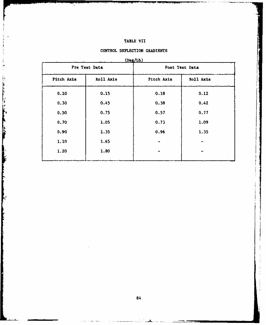
TABLE VII
CONTROL DEFLECTION GRADIENTS
(Des/Lb)
Pre Test Data Post Test Data
Pitch Axis Roll Axis Pitch Axis Roll Axis
0.10 0.15 0.18 0.12
0.30 0.45 0.38 0.42
0.50 0.75 0.57 0.77
0.70 1.05 0.73 1.09
0.90 1.35 0.96 1.35
1.10 1.65 - -
1.20 1.80
84

Since the data from the last calibration flight is probably more accurate,that data was used throughout the remainder of the report.
TEST METHODS AND CONDITIONS
Pre-test and post test calibration sorties were planned to determinethe sidestick force and deflection gradients for the test conditions.
*The data from the pre-test calibration sortie was used to determine thevariable stability system gain (potentiometer) settings to obtain thedesired gradients. The oscillograph was used to record the pilot forceinputs, sidescick deflections, and aircraft response. The pre-testcalibration was repeated twice because of oscillograph feed systemfailure during the first two attempts. The post test calibration
-~ sorties was used to determine the NT-33A apparent open loop dynamicsand to recheck the force and deflection gradients as. the end of theprogram.
V ~The tests were conducted using the config~urations shown in Figure 47.Config'.rations 27, 16 and 11 were found to be likely candidates for anoptimal configuration by USAF TPS Class 76B (Appendix B). Therefore,the nine configurations shown as initial were examined during the first
eight data sorties to identify regions that justify further testing.The pilot ratings from the first eight sorties showed no clear preferenceIfor any configuration and large variability between pilots. Therefore,for the second eight sorties, configurations outside the initial set ofpoints were used for most of the evaluations. Throughout the firstsixteen data sorties, configurations were chosen in a pseudo-randomfashion where engineering judgement was used to avoid an excessivenumber of evaluations of any configuration (while neglecting others) orevaluating nearly identical configurations on the same sortie. At thecompletion of the fourteenth data sortie, the trends which will bediscussed under Analysis of Configurations were detected by the projectengineers. Therefore, the last two data sorties were used to verifythe sensitivity conclusions by traversing the test envelope in thedirection of maximum sensitivity change. Also, a near optimal configurationwas chosen based on pilot comments and ratings. This near optimalconfiguration was evaluated on the last data sortie. Throughout the test,evaluation pilots were never told which configurations they would evaluate.
Mission Description.
Each mission consisted of the following phases:
a. Pre-mission briefing
b. Takeoff and join-up
c. Tracking tasks, to include:
85
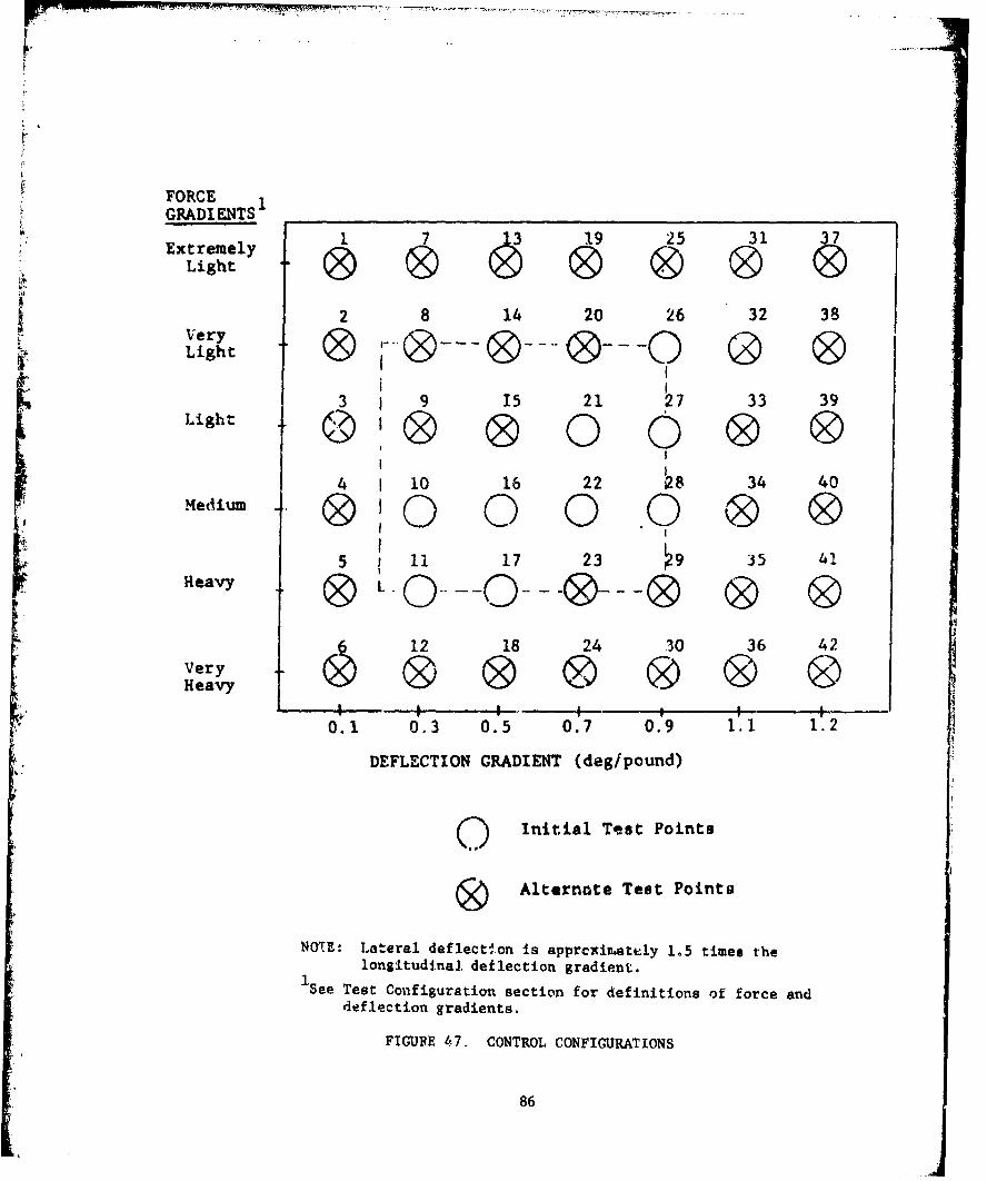
FORCEGRADIENTS
ExtremelyLigh
2 8 14 20 26 32 38VeryLight 0Light 3 9 15 21 27 33 39
SL,•. @ ® 0 0 0 ®4 I 10 16 22 a8 34 40
Medium 0 O 0 0 0S"' 0' 0 .0 ® 95 11 17 23 J9 35 41
""WHeavy 0 L .QQ. 0® 0 0
Very 0 &Heavy
0.1 0.3 0.5 0.7 0.9 1.1 1.2
DEFLECTION GRADIENT (deg/pound)
O. Initial Test Points
0 Alternate Test Pointo
NOTE: Lateral deflect-'.on is approxinately 1.5 times thelongitudinal, deflection gradient.
1.See Test Configuration section for definitions of force anddeflection gradients.
FIGURE 47. CONTROL CONFIGURATIONS
86

1. Formation work
2. Wind-up turn
3. 3-g turns with rapid reversals
4. 2½-g cine-track maneuver
d. Approach and landing task
e. Debriefing
Pre-Mission Briefing. Mission briefings were conducted by thetest mission aircrews and the project engineer monitoring that flight.The target aircrew consisted of a project pilot and project engineer.
Takeoff and Join-Up. The T-38 target aircraft made a militarypower takeoff 20 seconds after the NT-33 started his takeoff roll.After takeoff the test aircraft engaged the sidestick control systemand made small pitch and rol]. inputs to insure system stability and toobtain initial pilot comments for that particular configuration. TheT-38 then assumed the lead and climbed to 15,000 to 17,000 feet MSLwith the test aircraft flying either a loose route or close formationposition.
Tracking Tasks. Five tasks were evaluated for each configuration:Close formation, wind-up turns, 3-g turns with rapid reversals, a 23-gcine-track maneuver, and closed pattern touch and go landings. Threeconfigurations were evaluated on all but three sorties, which werelimited due to system malfunctions. Rudder was used on only the closeformation and cine-track maneuvers. Each task was repeated until thetest aircraft pilot was satisfied with the evaluation.
Formation. Prior to assuming the close formation pcsition aftera configuration change, a quick evaluation of the aircraft's pitch androll response, stick force gradients and stick deflection was made inthe extended trail posivi.on. The test aircratt then assumed a closeformation position. Wing tip clearance was maintained as was nose/oilIseparation in case. of NT-33 flight control system malfunction. Thetarget aircraft then performed a series ijf modified lazy-8 maneuverswith up to 90 degrees of bank within an airspeed range of 180 to 350 KIAS.Each formation eval.ticn also included at least one wind-up turn of upto 3½-g's.
Wind-Up Turn. The project pilot dropped back 1500 feet behindthe target aircraft as determined by sl-ht picture. When the projectpilot indicated ready, the target pilot began a constant speed (280 KIAS)"slowly increasing G (approvimately 0.2 G/sec) turn, up to a maximum of3.2-g's (where moderate buffet occurred). The project pilot aggressivelytracked the target aircraft's forward canopy throughout this maneuver,using a gunsight depression of 0 mils to help eliminate pendulum effects.
A7
Constant-G Reversals. After completing the wind-up turn, theproject pilot again positioned his aircraft 1500 feet behind the targetaircraft. The target aircraft then established a 3-g turn, maintainingairspeed between 280 to 300 KIAS. Upon a call from the test aircraft,the target would then execute a rapid unloaded reversal. The testaircraft would delay 3 to 4 seconds, then reverse and rapidly reacquireand track the target.
Cine-Track Maneuver. Having completed the constant-g reversals,the project pilot would stabilize 1500 feet behind the target aircraft.The target aircraft would then begin a constant 280 KIAS, 2½-g turn.On the project pilot's call, the target aircraft would perform aconstant 21-g barrel roll through 540 degrees of roll. After completingthe roll the target aircraft would continue the 21-g turn at 280 KIASand repeat the barrel roll on the project pilot's call. At the end ofthis set of maneuvers, the safety pilot would pe':form an in-flightdebriefing of the project pilot. The project pilot would then beginthe set of tracking tasks with the next configuration.
Landing Tasks. Each configuration was examined during closedtraffic patterns with touch and go landings. The first pattern wasflown in the conventional manner, using 140 KIAS in the final turn and130 KIAS on final approach. On the second pattern in each configuration,an intentional base-to-final overshoot and balloon during flare wasperformed to examine the ease of rccovery. The final approach configurationon all approaches was: gear, 30 degrees flaps and speed brake.
Post-Mission Debriefing. Each mission ended with a debriefingconducted by the project engineer who monitored the flight and includedthe project pilot, target pilot, and the safety pilot. The debriefingwas normally conducted immediately after the mission.
TEST RESULTS AND ANALYSIS
Analysis of Configurations.
The Cooper-Harper ratings by themselves (Figure 48), did not Identifythe particular problems associated with the test configurations. Forexample, the ratings for two configurations may have both been 5, butone because of over sensitivity and the other because of sluggishness.However, when used in conjunction with the pilot comments (Figure 49),both the problem and its impact could be established. This allowedthe determination of the boundaries described in the following paragraphs.
In depth analysis of the pilot ratings and comments ievealed fourseparate boundaries to the region of acceptable handling qualities foraix-to-air tasks. Similar boundaries exist for the landing task; however,the acceptable region was somewhat larger. The exact locations of theseboundaries may vary with aircraft dynamics, control system dynamics,airspeed, control inpuit prefilters, sidestick'geometry, aircraftmaneuverability, and pilot physiology; similar boundaries will probablybe present in any highly maneuverable aircraft with sidestick controller.Two of the boundaries were based on anthropometric considerations wherethe sidestick force or deflection exceeded the pilot's wrist capabilities.
88
- -,~~
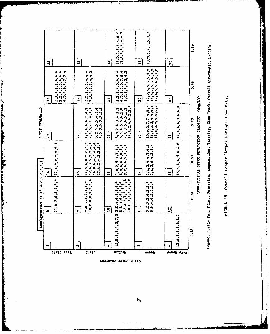
4# 4t f:a.
""s q4. 19, i- ItqLi
444ca~~~~ a 0 aaf0?
141 44 c 40* L; L! a1 a a
h" - a j- 0 .40 X o
a en . a aum4
$4 a.
1- r4~ -4 *4 1. 1Uý0;C 4 t
a4 4-4 14
19; a. li ; i;.
44 1.'
P6~~ V6-4*40 4
-~4 aa ~
(.44?:1 ; .. S '..06.P4 . 4
301 *. O '4171 uN POa 4Aaa 4%WG /20
I P2a 0102 44 l.641.
* 0U6 4 aa aa 4 * 89
FIGURE 49 PILOT COMMENTS,
General Comments:
(1) Hitting stick deflection stops before running out of pitch or rollauthority (i.e., changing from motion to pressure cues) was very objectionable.
(2) More precise tracking capability was apparent with small motion cuesrather than strictly pressure cues.
(3) The +10 mil lateral oscillation of the NT-33 was very objectionableduring all evaluations.
(4) The heavy rudder forces and very limited rudder pedal movement wasvery objectionable.
(5) Pilots desired that the throttle and stick be symmetrically located.
Pilot Codes:
A-DanielIC -SaxonD - LaBarge
Configuration # 4: (B)
(1) Control harmony OK in formation but was a problem in cine-track.(2) Too sensitive - continuous pitch bobble and wander - unable to
attain a tracking solution. Laterally too sensitive in formation.(3) Overshoots in pitch and roll during acquisition tasks.(4) Use of rudder helps cut lateral pipper wander.
Configuration #t 6: (A)
(1) Formation: sluggiah, slow roll response, force too high (laterally).Longitudinal forces too high. Stiff stick.
(2) Tracking good once pipper on target but corrections difficult due tosluggish response.
(3) Fatiguing without use of trim.(4) Used knee to get desired roll response to the right.(5) Sensitivity too low, harmony OK but too stiff.(6) Safety observar's comment - "One of the best peformning configurations
observed once target acquired."
Configuration # 8: (B)
(1) Very poor harmony.(2) Constant lateral oscillation in formation plus pitch bobble.(3) Lateral oscillation could be dangerous.(4) Controllability in question under very heavy workload due to very
bad lateral oscillation during tracking.
90

FIGURE 49 (continued)
Configuration # 9: (C)
(1) A little too sensitive laterally.(2) 5 to 6 mil pitch and roll oscillations during fine tracking - a
little too sensitive in both axes.(3) Lateral overshoot tendency.(4) Forces a little heavy in landing pattern, but overall acceptable
in the pattern.
Configuration # 10: (A,BC)
(1) Slight pitch bobble (+4 mils).(2) No PIO tendencies.(3) Rapid roll inputs require too much force, max roll rates too slow.(4) Need lighter stick forces to the right than to the left.(5) Only pilot C felt it was too sensitive.(6) Small overshoots in pitch during gross acquisition.
Configuration # 11: (B,C)
(1) Acceptable, but had a very slight pitch bobble in fine tracking tasks.(2) Lateral pipper wander gave the most problem in tracking.(3) Much less sensitive in roll than pitch, increasing workload to make
fast rolls. In landing task, stick was a little stiff and heavy with pitchPIO tendency.
(4) Control harmony hampered accurate tracking.(5) Pilot B felt that the rudder helped during cine-track, but that the
forces were too high (stick).
Configuration # 14: (A, landing task only)
(1) Very sensitive aircraft, but acceptable.(2) Light stick forces could lead to secondary stall, balloon during flare,
and takeoff over-rotation tendencies.
Configuration # 15: (A,B.,D)
(1) Stick forces a little too light in pitch. Tendeicy to overshcotlongitudinally.
(2) +4 mil longitudizual pipper bobble. Pitch sensitivity decreased byusing some forward trim.
(3) Lateral forces a little too heavy. Difficult to get roll ratesestablished or stopped. Good for fine tracking, but poor for gross acquisition.
(4) Poor control force harmony. Landing task assigned Cooper-Harper of 1. (A'(5) Seemed to have pitch and lateral stick force lightening.
Configuration # 16: (B,C)
(1) Difficult to acquirs target due to pipper wander.(2) Control hazmony poor in tracking tasks, acceptable in formatior.(3) Pitch bobble and lateral wander during tracking.
91

FIGURE 49 (continued)
(4) Harmony not as much of a problem when using rudder during cine-track.(5) Longitudinal stick force vs. deflection too high in landing flare.
Mild roll PIO on touch & go landings.
Configuration # 17: (A,C)
(1) Stick was heavy.(2) No pitch bobble was noticed.(3) Lateral forces much too heavy, especially when trying to quickly reverse.(4) Some directional drift apparent when tracking and tendency to overshoot
directionally during acquisition.(5) Felt insensitive and sluggish in landing tasks. Lateral PIO tendency.
Configuration # 18: (B)
(1) Trim continually required to reduce forces in formation.(2) Control harmony OK.(3) Pitch v-iry nice in tracking (5 mil maximum excursions), but had 10 to20 mil lateral pipper wander.(4) Lateral axis is the only problem in tracking.
(5) Acquisition task not bud but some overshoot in both pitcl- and roll.(6) Rudder completely eliminated wander.(7) Longitudinal force much too heavy - very sluggish in pitch and roll.
Full aft stick required in flare.
Configuration # 21: (A,B,C,D)
(1) Too sensitive in both axes - PIO tendency.(2) Control harmony not gcod.(3) Bad overshoots both in pitch and roll during acquisition.(4) Pitch babble (6 to 8 mils) and annoying wander during tracking,
helped somewhat by rudder.
Configuration # 22: (A,B,C)
(1) Control harmony was good.(2) Slight tendency to overshoot in pitch during gross acquiaition in
heavy workload environment (pilots B & C only).(3) A & C thought pitch was just a litile sensitive. B thought it too
sensitive.(4) Roll forces were too high and should be a little lighter.(5) In landings, controls slightly sluggish. Hlarmony was OV. Pilot A
reached aft stop on landing and felt the stop indicated he had ran out of pitchccntrcl - very objectionable. Too much stick motion.
Configuration # 24: (B,C,D)
(1) Fine tracking OK once established, but gross acquisition was difficultdue to high stick forces.
(2) Stirk forces too high. Must horse airplane around as it responds tooslowly. Sluggish responses.
92
FIGURE 49 (condinued)
(3) Poor responses in landing pattern. Very heavy forces. Hard to startand stop roll rates. Hit aft stop at touchdown which was very objectionable.Stick deflections too large.
Configuration # 24: (D)
(1) Feels rubbery in formation - difficult to predict response in bothaxes, especially pitch. Longitudinal stick deflection too high.
(2) Pitch PIO apparent when tracking under G load. 5 to 10 mil pipperwander but no overshoot in either pitch or roll during acquisition.
(3) Controls felt too stiff.(4) Fast roll produces r&.cheting.(5) Forces and deflections too high in both axes.(6) Landing in high crosswInd difficult due to lack of response. Unstable
spiral mode apparent due to necessity to hold large oppobite aileron force inturns in pattern. Controllability in question.
Ccnfiguration # 26: (B•D)
(1) Lateral sensitivity too great - lateral PIO tendency.(2) Large lateral overshoots.i3• Poor control force harmony.
Conziguration # 27: (A,B)
(1) Pitch was too sensitive.k2) Lateral wander was present, but was not as pronounced as the pitch
bobble.(3) Roll oscillations & overshoot were present during gross acquisition.(4) Compensation required was moderate to high during tracking.(5) Pilot A thought that pitch was too sensitive in formation, but
pilot B liked it.(6) In the landing tasks, pitch was too sensitive, control harmony was
good, forces were light, and there were no lateral problems.
Configuration # 28: (BC,D)
(1) Good in formation - however, slight pitch bobble when trimming dueto the sensitive stick being affected during trim button operation.
(2) Good control force harmony.(3) Overshoots in both axes during gross acquisition - both axes a little
too sensitive - difficult to prevent overshoots.(4) Mild pitch and lateral bobble during tracking.(5) Difficult to precisely predict response in both axes.(6) Stick forces too light in both axes.(7) In landing tasks, full aft stick used at touchdown, but pitch control
was nice. Too sensitive laterally on final.
93
I .
FTGURR, 49 (continued)
Configuration # 29: (B.D)
(1) Format-ion - no adverse comment - comfortabla, easy to stay in close.k2) Tracking under C-load - 3 to 4 mil pitch bobble. Requires pit,:h trim
"to keep force gradient zomfortable.(3) Slight directional overshoot in gross acquisition -. good In pitch,
very responsive and had good feel.(4) Control harmony very nice, sensitivity OK.(5) Lateral wander in cine-track not helped much by use of rudder.
SUsing rudder causes overshoots.(6) Hit lateral stops when attempting to roll quickly - deflections too
Ulrge in both pitch aid roll.(7) Only really objectionable .naracteristic is that stick motions aie
too large in both axes.
Conflguration # 53: (D)
0(.) Too sensit've in pitch. 5 to 8 mil bobble during fine trackl;',g.Pitch overshoots during gross acquisitions.
"(2) Control harmony satisfactory.(3) Hard to make precise :orrections in pitch or roll.
Configuration # 34: (A,D)
(1) Stick felt loose. Exc.asive deflections required.(2) Too much aft stick requ1ired to increase G.(3) 5 to 10 mil pi;ch bcbble during fine tracking.(4) During landing tasks, far too much motion required. Hitting stops
gave the impression of a lack of adequate control authority. Pitch controljerky with stick against stop during flare. Very high stick forces throughoutpattern.
Configuration # 35: (D)
(1) Pitch sensitivity OK, but was laterally stiff.(2) Lateral overshoots & sluggish ailerons prevented desired performance
levels.(3) Pitch control good during fine tracking, but had mild overshoots
during gross acquisition tasks.(4) Poor control force harmony - felt like higher lateral force gradie2nt
than longitudinal.(5) In landing task, lateral axis was satisfacto-y. However, plcch axis
was bad as stick forces were too high and excessive Aeflection was requirvd.Very sluggish pitch response that required improvement.
Configuration X: (C)
(1) No overshoot or wander tendencies.(2) No pitch or roll compensation reauired.(3) Ersy to control, comfortable good performance.(4) [L.cellent for fine tracking and gross acquisition maneuvering.(5) Best config-oration evaluated, comfortatle in landing pattern.
94
-
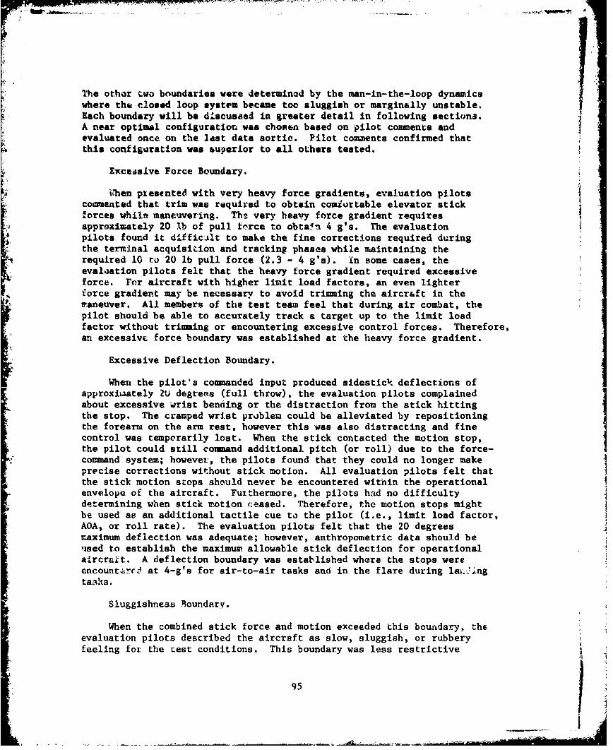
The other two boundaries were determined by the man-in-the-loop dynamicswhere the closed loop system became too sluggish or marginally unstable.Each boundary will be discuseed in greater detail in following sections.A near optimal configuration was chosen based on pilot comments andevaluated once on the last data sortie. Pilot comments confirmed thatthis configuration was superior to all others tested.
Exceasive Force Boundary.
Whben piesented with very heavy force gradients, evaluation pilotscommented that trim was required to obtain comfortable elevator stickforces while maneuvering. Ths very heavy force gradient requiresapproximately 20 lb of pull tfrce to obtain 4 g's. The evaluationpilots found it difficilt to make the fine corrections required duringthe terminal acquisiLion and tracking phases while maintaining therequired 10 to 20 lb pull force (2.3 - 4 g's). in some cases, theevaluation pilots felt that the heavy force gradient required excessiveforce. For aircraft with higher limit load factors, an even lighterforce gradient may be necessary to avoid trimming the aircr&ft in themaneuver. All members of the test team feel that during air combat, thepilot should be able to accurately track a target up to the limit loadfactor without trimming or encountering excessive control forces. Therefore,an excessive force boundary was established at the heavy force gradient.
Excessive Deflection Boundary.
When the pilot's commanded input produced sidestick deflections ofapproxiiaately ZU degrees (full throw), the evaluation pilots complainedabout excessive wrist bending or the distraction from the stick hittingthe stop. The cramped wrist problem could be alleviated by repositioningthe forearm on the arm rest, however this was also distracting and finecontrol was temporarily lost. When the stick contacted the motion stop,the pilot could still command additional pitch (or roll) due to the force-command system; however, the pilots found that they could no longer makeprecise corrections without stick motion. All evaluation pilots felt thatthe stick motion stops should never be encountered within the operationalenvelope of the aircraft. Furthermore, the pilots had no difficultydetermining when stick motion ceased. Therefore, the motion stops mightbe used as an additional tactile cue to the pilot (i.e., limit load factor,AOA, or roll rate). The evaluation pilots felt that the 20 degreesmaximum deflection was adequate; however, anthropometric data should beused to establish the maximum allowable stick deflection for operationalaircraft. A deflection boundary was established where the stops wereencountirzO at 4-g's for air-to-air tasks and in the flare during la.'Ingtasks.
Sluggishness Boundary.
When the combined stick force and motion exceeded this boundary, theevaluation pilots described the aircraft as slow, sluggish, or rubberyfeeling for the Lest conditions. This boundary was less restrictive
95
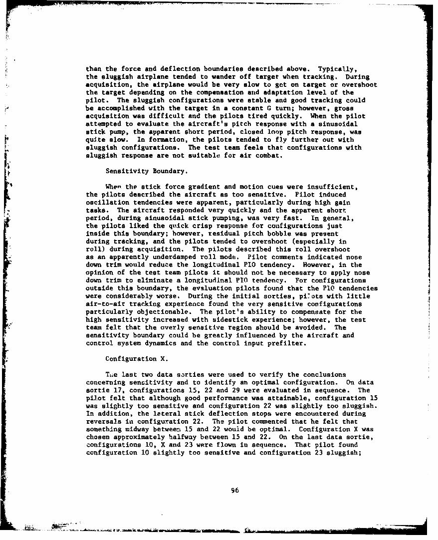
than the force and deflection boundaries described above. Typically,the sluggish airplane tended to wander off target when tracking. Duringacquisition, the airplane would be very slow to got on target or overshootthe target depending on the compensation anid adaptation level of thepilot. The sluggish configurations were stable and good tracking couldbe accomplished with the target in a constant G turn; however, grossacquisition was difficult and the pilots tired quickly. When the pilotattempted to evaluate the aircraft's pitch response with a sinusoidalstick pump, the apparent short period, closed loop pitch response, wasquite slow. In formation, the pilots tended to fly further out withsluggish configurations. The test tearn feels that configurations withsluggish response are not suitable for air combat.
4 Sensitivity Boundary.
When the stick force gradient and motion cues were insufficient,the pilots described the aircraft as too sensitive. Pilot inducedoscillation tendencies were apparent, particularly during high gaintasks. The aircraft responded very quickly and the apparent short.period, during sinusoidal stick pumping, was very fast. In general,the pilots liked the quick crisp response for configurations justinside this boundary; however, residual pitch bobble was presentduring tracking, and the pilots tended to overshoot (especially inroll) during acquisition. The pilots described this roll overshootas an apparently underdamped roll mode. Pilot coumments indicated nosedown trim would reduce the longitudinal PIO tendency. However, in theopinion of the test team pilots it should not be necessary to apply nosedown trim to eliminate a longitudinal P10 tendency. For configurationsoutside this boundary, the evaluation pilots found that the P10 tendencieswere considerably worse. During the initial sorties, pilots with littleair-to-air tracking experience found the very sensitive configurationsparticularly objectionable. The pilot's ability to compensate for thehigh sensitivity increased with sidestick experience; however, the testteam felt that the overly sensitive region should be avoided. Thesensitivity boundary could be greatly influenced by the aircraft andcontrol system dynamics and the control input prefilter.
* Configuration X.
Li.e last two data sorties were used to verify the conclusionsconcerning sensitivity and to identify an optimal configuration. On datasortie 17, configurations 15, 22 and 29 were evaluated in sequence. Thepil~ot felt that although good performance was attainable, configuration 15was slightly too sensitive and configuration 22 was slightly too sluggish.In addition, the lateral stick deflection stops were encountered duringreversals ia configuration 22. The pilot cosmmented that he felt thatsomethi.ng midway between 15 and 22 would be optimal. Configuration X waschosen approximately halfway between 15 and 22. On the last data sortie,configurations 10, X and 23 were flown in sequence. That pilot foundconfiguration 10 slightly too sensitive and configuration 23 sluggish;
96
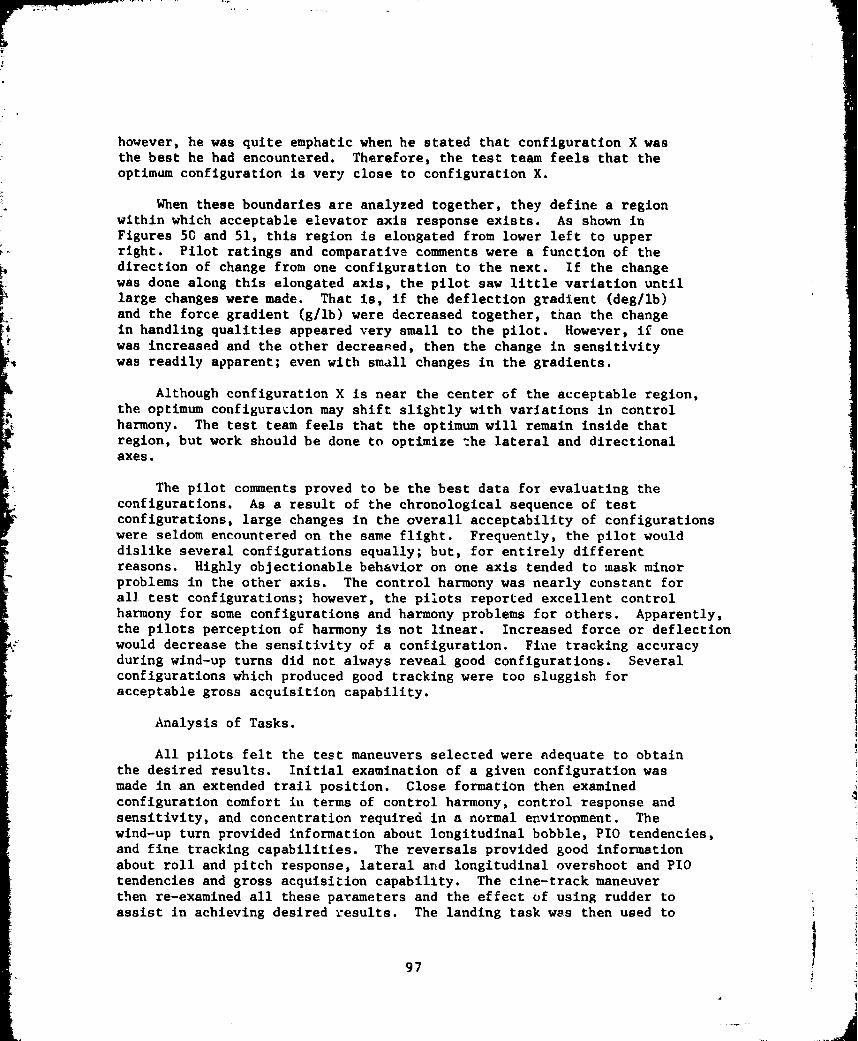
however, he was quite emphatic when he stated that configuration X wasthe beat he had encountered. Therefore, the test team feels that theoptimum configuration is very close to configuration X.
When these boundaries are analyzed together, they define a regionwithin which acceptable elevator axis response exists. As shown inFigures 50 and 51, this region is elongated from lower left to upperright. Pilot ratings and comparative comments were a function of thedirection of change from one configuration to the next. If the changewas done along this elongated axis, the pilot saw little variation until
IN large changes were made. That is, if the deflection gradient (deg/lb)and the force gradient (g/lb) were decreased together, than the. changein handling qualities appeared very small to the pilot. However, if onewas increased and the other decreased, then the change in sensitivitywas readily apparent; even with small changes in the gradients.
Although configuration X is near the center of the acceptable region,the optimum configurazion may shift slightly with variations in controlharmony. The test team feels that the optimum will remain inside thatregion, but work should be done to optimize -ýhe lateral and directionalaxes.
The pilot comments proved to be the best data for evaluating theconfigurations. As a result of the chronological sequence of testconfigurations, large changes in the overall acceptability of configurationswere seldom encountered on the same flight. Frequently, the pilot would
dislike several configurations equally; but, for entirely different
reasons. Highly objectionable behavior on one axis tended to mask minorproblems in the other axis. The control harmony was nearly constant forall. test configurations; however, the pilots reported excellent controlharmony for some configurations and harmony problems for others. Apparently,the pilots perception of harmony is not linear. Increased force or deflection
* ~would decrease the sensitivity of a configuration. Fiaie tracking accuracyduring wind-up turns did not always reveal good configurations. Severalconfigurations which produced good tracking were too sluggish foracceptable gross acquisition capability.
Analysis of Tasks.
All pilots felt the test maneuvers selected were adequate to obtainthe desired results. Initial examination of a given configuration wasmade in an extended trail position. Close formation then examinedconfiguration comfort in terms of control harmony, control response andsensitivity, and concentration required in a normal environment. Thewind-up turn provided information about longitudinal bobble, PIO tendencies,and fine tracking capabilities. The reversals provided good informationabout roll and pitch response, lateral and longitudinal overshoot and PIOtendencies and gross acquisition capability. The cine-track maneuverthen re-examined all these parameters and the effect of using rudder to
assist in achieving desired results. The landing task was then used to
97
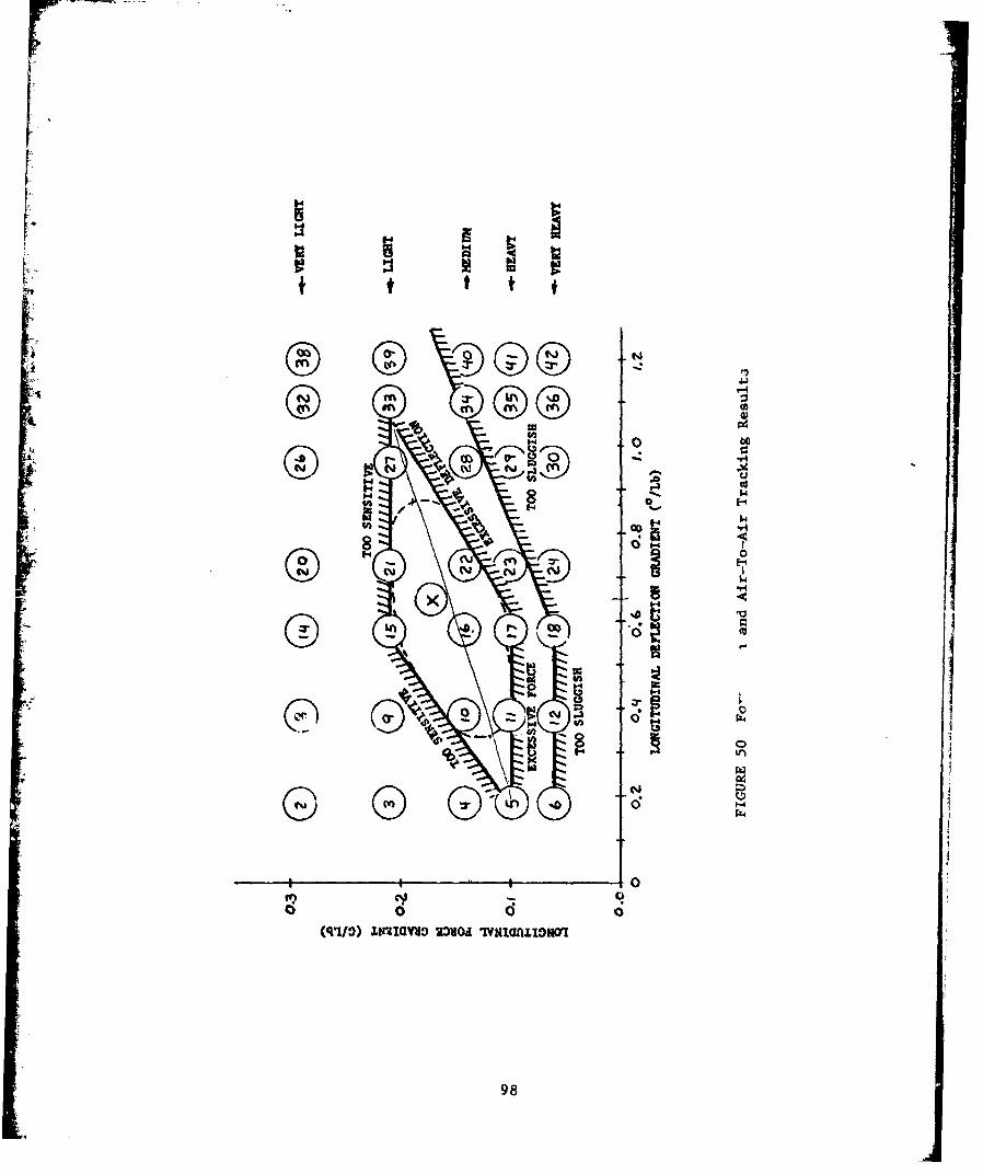
Nos
14
0 vC
H - 04
0 .44
IIqal RaVU 71.4IDMr
4 y) -98
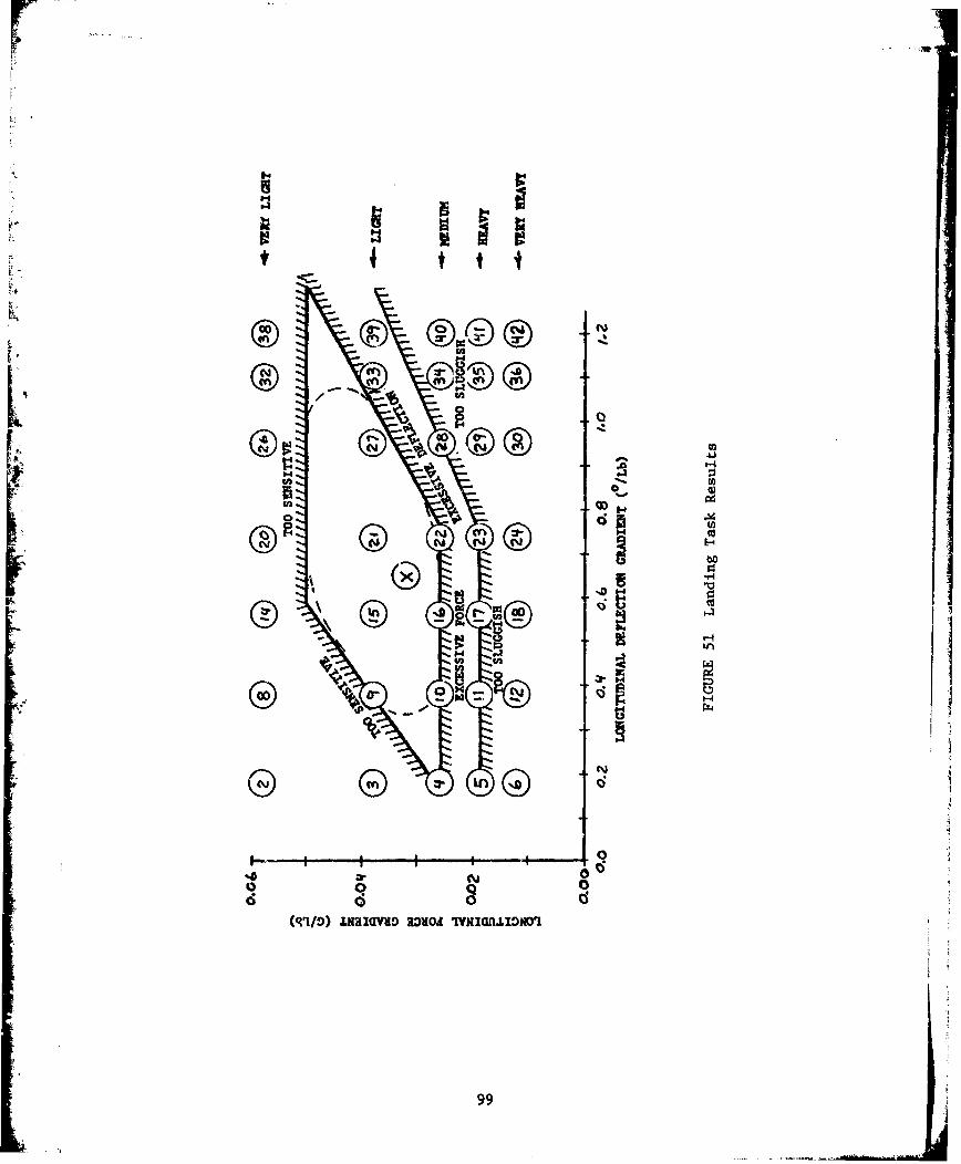
8*4 a-
00 tot
06
0 t
- C, rN00
40O I0 U)ilnw
o9
re-examine each control configuration in a low speed, low altitude,power approach condition to determine if a given configuration wassuitable for several totally different tasks.
The test team members further felt that the optimal area of stickmotion and stick force gradient was determined for the given aircraftdynamic characteristics. It was felt that similar testing should beaccomplished with various dynamics configurations to determine theeffects of aircraft dynamics changes on pilot ratings of given controlconfiguration. Additional testing should also be accomplished on air-to-ground tracking tasks.
All test maneuvers were flown without the use of the rudder exceptfor the cine-track maneuver. This was done to remove one variable whichwould have possibly masked deficiencies in the other two axes whichwould otherwise be apparent. Conversely, the test team pilots feltthat acquiring and tracking without the use of rudder was unrealistic ina Itreal world" sense. It was therefore concluded that once the rudderforce/deflection gradients in the NT-33 are optimized that all tasksshould be flown both with and without the use of rudder. It Would thusbe possible to determine the effect on pilot ratings of using rudder.
Analysis of Pilot Factors.
Throughout the test program, certain pilot fa~ctors were found toinfluence the ratings of the different configurations and, in some cases,the pilot's opinion of the configuration. Initially, they were mostinfluenced by the pilot's background. This became less of a factor aseach pilot became more proficient at the tasks, and the opinions andratings became more comparable between any two pilots. It was evidentthat at least two practice sorties with the sidestick controller were
* necessary for each evaluation pilot before achieving comparable results.None of the project pilots had ever flown sidestick equipped aircraftbefore this program, but all pilots thought that the sidestick Issuperior to the center stick for these type tasks.
Available sidestick deflection became a factor which affected pilotopinion of certain configurations. If a pitch stop was reached, thepilot's immediate impression was that he had nio more elevator authority,even though more force could command more pitch. This was not a factorwith light force gradients or small deflection gradients.
The lateral control force gradients were the same for left and rightroll. This was acceptable for the lighter force gradients, but co-iMandingright roll was more difficult than left roll with heavier force gradients.The possibility of different gradients left and right should be investigated.
The pilots found that better pitch control was available if they wereholding moderate back force while tracking. Pilot comments indicated thatthe heavier gradients would require nose up trim, while tracking withlighter gradients might be improved with nose down trim. Neither was felt
100

tc be satisfactory, as each resulted in a higher workload. Of significancein this comment, however, is the idea that a poor configuration might bemade to appear acceptable during certain tasks by the use of trim.
An annoying characteristic of the NT-33A was the lack of symmetrybetween the throttle and the sidestick in position, motion required, andforces required. These should be optimized for better harmony andreduced workload.
Finally, the rudder forces were too high for most configurationsduring the cine-track maneuver. This lack of harmony between the sidestickand rudder affected some ratings and increased the workload. Betterrudder har'mony could possibly increase the envelope of acceptablehandling qualities.
CONCLUSIOWS AND RECOMMENDATIONSThe primary objective of tnis test program was achieved iT that
the influence on pilot ratings of varying sidestick force and deflectiJ'gradients was detenined. For thn specific aircraft and control systemdynamics used, boundaries were determined which define the region ofacceptable handling qualities. The secondary objectives of quantitatively
Iverifying pilot tracking performance and investigating control harmonywere not achieved due to instrumentation malfunctions and aircraftmaintenance problems which resulted in the loss of a significant numberof data sorties. The test team did not consider the lack of quantitativetracking data a significant deficiency. However, the test team feltthat control harmony variation is a fertile area for future test efforts.
None of the evaluation pilots had previously flown a sidestickconfigured aircraft and all pilots involved considered the sidestick tobe superior to the centerstick controller for air combat maneuvering.Further, a nearly optimal control configuration was identified.
For a highly maneuverable aircraft with a sidestick controller, theregion of acceptable handling qualities will be bounded by limits ofexcessive force, deflection, sensitivity and sluggishness. The locationof these boundaries may vary with airframe and control system dynamics,control input prefiltere, sidestick geometry, aircraft maneuverability,and pilot physiology and adaptation. The force gradient should be suchthat the pilot could accurately track a target up to the limit loadfactor without encountering excessive control forces or the need to trim.For a sidestick with motion, the motion stvps should never be encounteredwithin the operational envelope. However, motion stops can be used toprovide tactile cues at the extremities of the envelope. Keeping in mindthat control harmony was kept constant throughout the test, analysis ofpilot comments further showed that the pilots' perception of control
101
harmony was not linear. Maximum stick motion should not exceed thephysiological litnits of the pilot.'s wrist and anthropometric data shouldbe used to establish the maximum allowable stick deflection for operationalaircr aft.
When the stick force gradients were too small and the deflection
gradients too large, the closed loop pilot-aircraft system was sluggishand slow to respond. Although sluggish configurations frequently prodiucedgood fine tracking performance they were judged not suitable for a fighteraircraft due to the difficulties encountered in gross acquisition. Whenboth force and deflections gradients were reduced simultaneously, pilotsdetected only slight variations in handling qualities. Pilots reportedthose configurations wherein the force gradient was increased and deflectiongradient decreased to be much more sensitive to control inputs. However,when force gradients were increased and deflection decreased beyond certainlimits, the closed-loop system became overly sensitive and pilot inducedoscillations resulted. Pilot comments suggested that by trimming toreduce ur increabe stick forces to a more comfortable level it may bepossible, in some cases, to improve tracking accuracy.
During the course of this evaluation several conclusions were drawnwhich may also apply to other, similar evaluations. Pilot commentsprovided the best data for evaluating the various configurations. Cooper-Harper ratings, by themselves, were a poor data source. However, whenused in conjunction with pilot comments, they were useful in establishingthe relative impact of a given problem. Highly objectionable behaviorin one axis tended to mask problems~ in the other. Due to pilot variabilityand adaptation, a statistical analysis of Cooper-Harper ratings wouldrequire a large number of evaluations of each control configuration toachieve an acceptable level of significance.
Initially, pilot ratings and comments were strongly influenced bybackground and training (Figure 52). This factor became less significant,however, as proficiency in flying the maneuvers and adaptation to theenvironment increased. Ratings and comments of the project pilots convergeddramatically at the end of the test program. Each flew at least two sortiesbefore comparable results were achieved. The value of quantitative datafrom relatively benign mbaneuvers such as constant G i~nd wind-up turns isquestionable; several very sluggish configurations which were totallyJunsuitable for a fighter air-craft produced excellent fine trackingcharacteristics.
The test team felt that the following areas should be investigatedduring future sidestick controller evaluations:
1. As previously mentioned, anthropometric. data should be used toestablish stick deflection limits for operational ~aircraft withsides tick controllers.
2. Variations in 'Lateral-directional control harmony should beinvestigated.
102
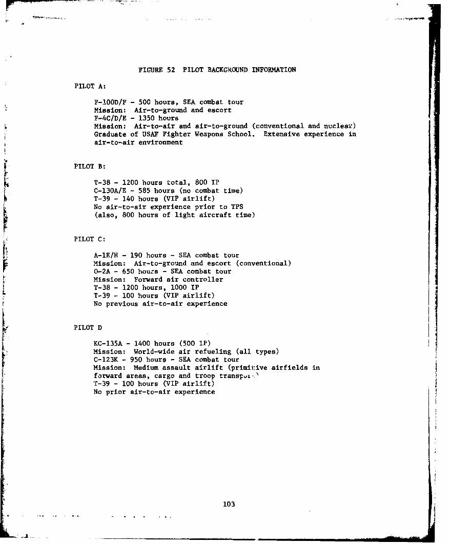
FIGURE 52 PILOT BACKGROUND INFORMATION
PILOT A:
F-!OOD/F - 500 hours, SEA combat tourMission: Air-to-ground and escortF-4C/D/E - 1350 hoursMission: Air-to-air and air-to-ground (conventional and nuclear)Graduate of USAF Fighter Weapons School. Extensive experience inair-to-air environment
PILOT B:
T-38 - 1200 hours total, 800 IPC-130A/E - 585 hours (no combat time)T-39 - 140 hours (VIP airlift)No air-to-air experience prior to TPS(also, 800 hours of light aircraft time)
PILOT C:
A-IE/H - 190 hours - SEA combat tourMission: Air-to-ground and escort (conventional)O-2A - 650 hours - SEA combat tourMission: Forward air controllerT-38 - 1200 hours, 1000 IPT-39 - 100 hours (VIP airlift)No previous air-to-air experience
PILOT D
KC-135A - 1400 hours (500 IP)Mission: World-wide air refueling (all types)C-123K - 950 hours - SEA combat tourMission: Medium assault airlift (primic.ive airfields inforward areas, cargo and troop transpu.).T-39 - 100 hours (VIP airlift)No prior air-to-air experience
103

rwell lipz
3. The possibility of differing gradients for left deflectionsversus right deflections should be investigated.
4. Additional testing should be accomplished on air-to-groundtracking tasks.
5. Testing should be accomplished wherein aircraft dynamics arevaried with control ratios held constant to determine the effectsof such variation on pilot ratings of a given control configuration.
104
APPENDIX D
TECHNICAL RESULTS AND DISCUSSION FROM USAF TEST PILOT SCHOOL
LETTER REPORT - 5 July 1978 "Limited Flight Evaluation of the
Effect of First Order Prefilters on the Handling Qualities of
Sidestick Controlled Aircraft" by Gregory V. Lewis, Captain, USAF;
Douglas M. Carlson, Captain, USAF; George J. Cusimano, Captain, USAF;
Menahem Shmul, Captain, IAF and Thomas V. Tilden, Captain, USAF.
ABSTRACT
A limited investigation was zonducted to determine the impact of
varying the corner frequency of a first order, lag prefilter in the
longitudinal and lateral axes of a sidestick controller for fighter
aircraft. The test aircraft, AFFDL's variable stability NT-33A, was
configured with the open loop dynamics of a high performance fighter
similar to an F-16. The results indicate an identifiable preference for
a particular prefilter for two out of the three tasks evaluated. Additionally,
varying the amount of sidestick force and deflection changed the preferred
prefilter. Data presented included pilot comments, pilot preferences,
fine tracking performance, and Cooper-Harper ratings. These data can be
used to further expand the data base on sidestick control configurations
generated in previous evaluations of this type. Data, target support,
practice, and calibration flights totalling 46 sorties and 65 flying
hours were flown at the Air Force F'ight Test Center, Edwards AFB,
California from 15 May 1978 to 9 June 1978.
r
105 j

TEST METHODS AND CONDITIONS
The test was conducted in two phases. Phase I was designed toexamine the effects of large variations in 'refilter corner frequencieson one stick Force/deflection and to determine the range of cornerfrequencies to be used in Phase II of the tes-c. Phase II testing was toanswer the specific objectives previously listed.
Phase I consisted of varying the corner frequency of the prefilterwhile keeping the stick force/deflection constant. The corner frequenciestested were 2, 4, 8, 12 and 16 radians per second. The force/deflectionconfiguration used was that recommended as best during the previouscests (Reference-- 2 and 3) as sbowa in Table VIII, point A. The sameprefiijer was used in both the longitudinal and lateral axes. Phase Iconsisted of four sorties.
In Phase II, both the corner frequency of the prefilter and thestick force/deflection characteristics were varied. The prefilter cornerfrequencies selected were 2, 8 and 16 radians per second. These cornerfrequencies were selected because the pilot evaluations of the prefiltersduring Phase I showed little variation in preference with smallervariat.ons in frequency. The stick force/deflection combinations whichwere used are pointa A and B on Table VIII. Again, large variations in theforce/deflection combinations were selected in order to increase thelikelihood of more discernible differences in overall prefilter and stickcombinations. Phase II consisted of 15 scrtiea.
Throughout the test each combination of force/deflection and prefilterwas flown approximately seven times. On each sortie three coafigurationswere evaluated. The test points for a particular sortie were chosen so asto minimize in-flight bias resulting from the order the points were flown.
Mission Description.
Each mission consisted of the following phases:
a, Premission briefing
b. Before takeoff
c. Takeoff and join-up
d. Air-to-air tracking
1. Constant "g" turn and reversal
2. Wind-up turn
3. Lazy eight
e. Recovery and landing
f. Debriefing
106

rJ
TABLE VIII
TEST CONFICURATICGS
A B
Longitudinal Lateral Longitudinal Lato:ral
Force Gradient 1.l67 g8lb 7 deg/sec/lb .167 g/lb 7 deg/sec/lb
Deflection Gradient 47 deg/ib 1.05 deg/lb .2 deg/ib .3 deg/16Jj
"orner Frequencies: 2 radians/second
4 radians/second
8 radians/second
12 radians/second
h n 16 radians/second
S*ft'hase I only.
Note: For the landing task, the force gradients were 20% of the
air-to-air fo-rce gradients shown. The deflection gradients were
unchanged.
107
Premission Briefing.
Premission briefings began at least one hour and a half before takeoff.The target aircraft was piloted by a project pilot to standardize targetmaneuvers. Project engineers flew in the rear cockpit of the targetaircraft. Evaluation pilots were not briefed on configuration parametersto prevent biasing results.
Before Takeoff.
After engine start, the evaluation pilot performed a normal stabilityand contrcl ground block which was recorded on magnetic tape. Beforetaking the runway, the evaluation pilot centered the pipper on a targetpositioned on the south side of runway 22. The gun camera was used todeternine camera boresight error.
Takeoff and Joinup.
Both aircraft used standard local area procedures in accordance with
AFFTC Manual 55-2. The NT-33A safety pilot made the initial takeoff andthe target aircraft took at least 10 second spacing. Joinup and climb-outto 14000 feet MSL was accomplished at 280 KIAS. During climb-out, thesafety pilot configured the aircraft for the first test configuration, andtransfered control to the evaluation pilot. After level off, an elevatorand a rudder doublet were recorded on magnetic tape. The lead was thenpassed to the target aircraft. Prior to testing each configuration, theevaluation pilot performed small coordination maneuvers to adjust to thenew configuration.
IAir-to-air Tracking.
Constant "g" turn and reversal. The target aircraft established a300 KIAS, 300 banked, level turn at 14000 feet MSL. The evaluation pilotstabilized cospeed at 1500 to 2000 feet behind the target. Following"READY" calls from both the target and tracker, the target rapidlyincreased the bank to maintain 2.0 "g's" without changing airspeed orpower setting. With 55 mils set in the fixed gunsight, the evaluationpilot delayed until the target was offset 100 mils and then aggressirelypositioned the pipper in the middle of the target aircraft exhaust nozzles.The evaluation pilot did not use rudders or trim during tracking. Afterapproximately 20 seconds of fine tracking, the evaluation pilot called"REVERSE" at which point the target pilot rapidly reversed nose high andthe evaluation pilot again delayed 100 mils before reacquiring. The grossacquisition and fine tracking were reaccomplished in the new direction.The exercise was terminated at the call of "NOCK IT OFF".
Wind-up turns. This maneuver was set up the same way as the constant"g" turn. After the standard initiation calls, the target aircraftmaintained 300 KIAS and slowly increased bank angle so as to increase "g"at a rate of approximately 0.2 "g" per second up to a maximum of 4 "g's".The target pilot slowly increased RPM so as to reach military power as hereached 4 "g 's". Tracking was accomplished as in the constant "g" maneuver.The exerc..ise terminated at 4 "g's", when the target reazhed heavy buffet,
108
g.,~ L

or at the call "YNOCK IT OFF". This maneuver wag accomplished in bothdirections.
Lazy eight. The target aircraft established level flight at 320 KIASand 13000 feet MSL and transmitted the direction of his first turn to theevaluation aircraft. The evaluation pilot stabilized 1500 to 2000 feetbehind, slightly below, and inside in the direction of tirn. After thestandard initial calls, the target executed a lazy eight maneuver. Thetarget pilot held a constant 2.2 "g's" throughout thE maneuver, attafningthe minimum airspeed of 250 KIAS when reaching approximately 900 of bankand turn. At 1800 of turn, the maximum airspeed of 3?0 KIAS was reachedas the tar-et brought his wings to level. The maneuver was continued inthe opposite direction. In order to maintain the desired separation,the target increased power dpproximately 5Z while decending and decreasedpower a like amount while ascending. Tracking was acromplished as in theconstant "g" maneu-ver.
Recovery and Landing.
The task evaluated during this phase of flight was the ability toattain and control the pitch attitude during the flare and touchdown.The evaluation pilot accomplished at least one landing in each configurationtested during the air-to-air portion of the flight. If two landingswere performed, the first wav with a normal approach while the second wasoffset from centerline to increase the task difficulty. The pilotevaluation and the configuration change were accomplished in level flightwhile entering the pattern for another landing. Either overhead orstreight-in approaches were flown, ensuring that final approach was atleast one mile long. No attempt was made to accomplish a precisiouglide path or spot landing.
Debriefing.
As soon as possible after each flight, a debriefing was conductedusing a detailed debriefing guide. As a minimum, the debriefing includedthe crewmembers from both aircraft.
RESULTS AND ANALYSIS
Four data sources were used to evaluate test results. Cooper-Harperpilot ratings were given after Pl1 air-to-air or landing tasks werecompleted in each configuration and are summarized in Figures 53 through 58.Pilot comments on each configuration were recorded in flight and aresummarized in Figure 59.
Although the Cooper-Harper ratings assigned to the variousconfigurations almost always fell in the range of 4 to 7, it was found
109
Mama"

__ 4)0
14 If 4- I.
r' r,
I r tr-
-r -T-
~ ~j~tiitj
I t ti~~ I,
4Hf-4A +N
Ugo
110
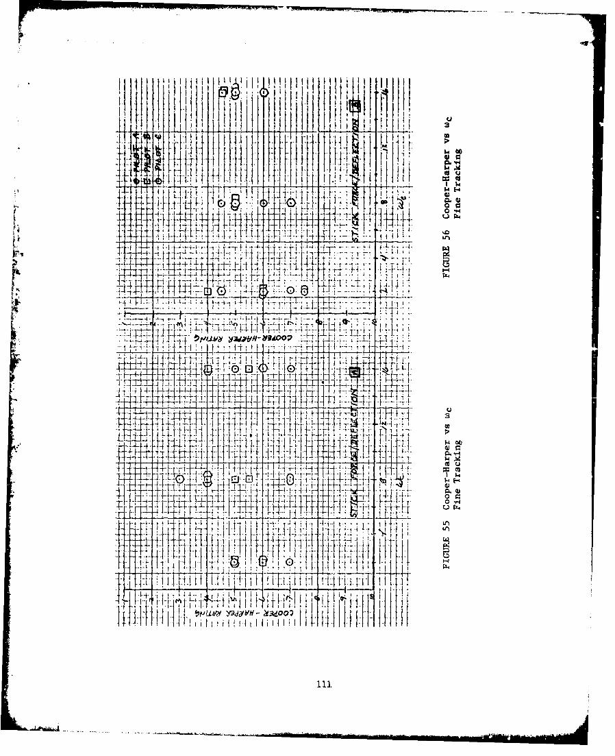
*j~ I-, j~. i i. i~-4- ~00, IU
11- Plhj4i
4 ~~
1H 414
-T 432. tt44 t 2 ) f -
til ti I -i--
++- '- 1414 4 ý i
4-14
4---O1 1.14ý1 4L4~~1:T4.tt
0 C.
0 -H
t I I .rmb y3SdyY Y~ 0
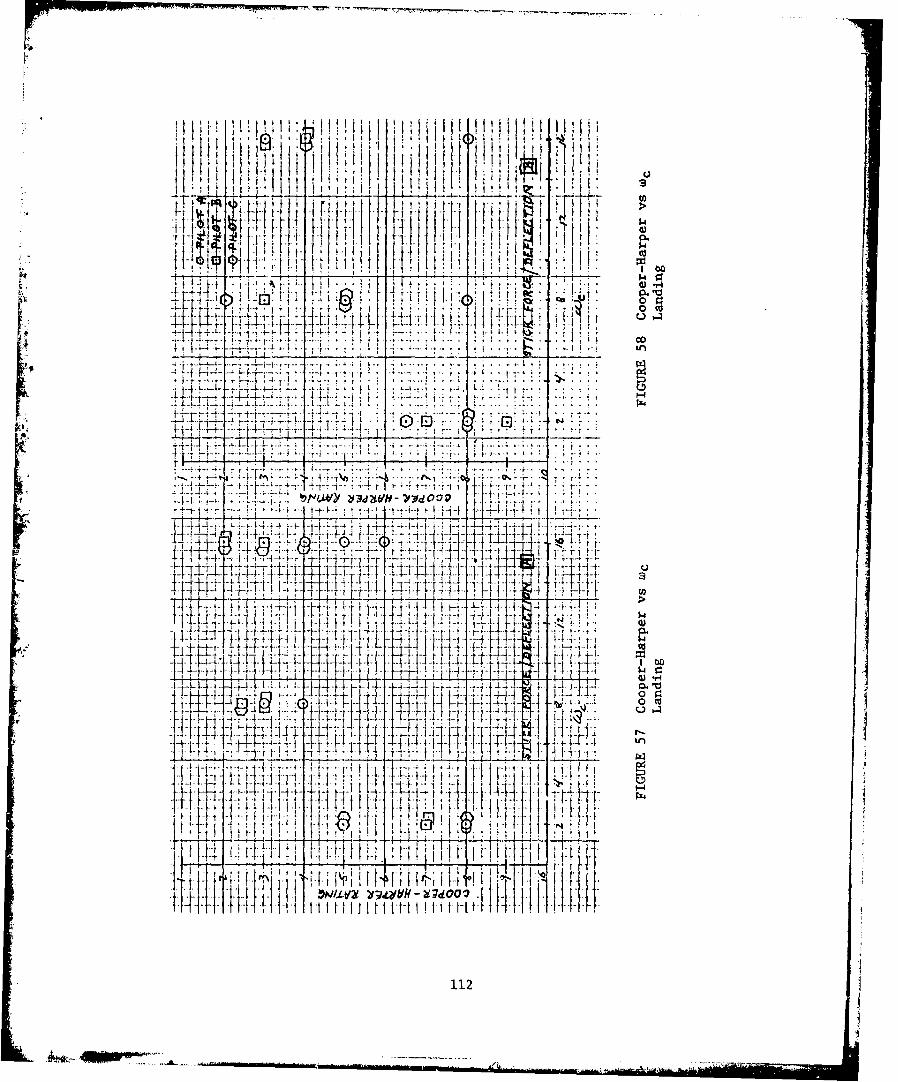
iii
..
1
ps. 4L .....
.i.4- 4-
*rqao -'I..-.. oLT-1
4 N . .. . ....... ...~ I t~L[ if 4
A-~1 44 t I __t 11Id Ti -At~7 :1 4
-r- -l t~~1~ TR~
it_ F lZt
11111 1rlu [41:[ H l
112
h**-
~ 4Ii~Mob"
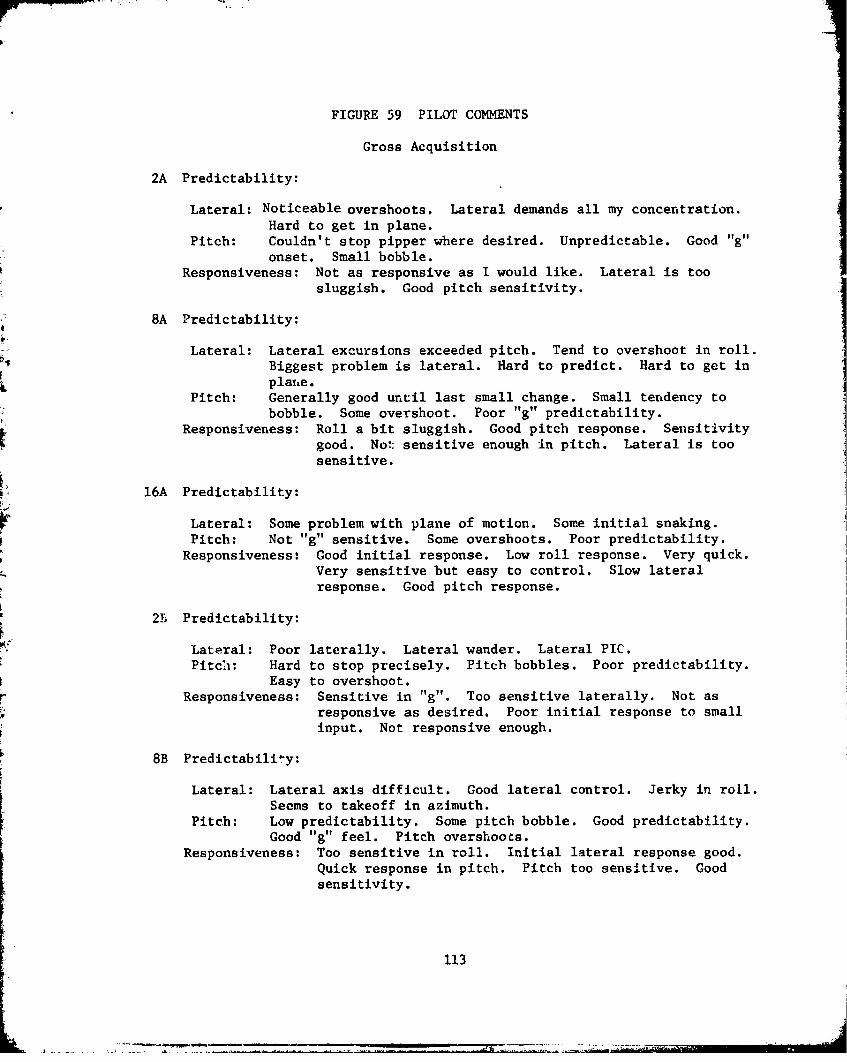
FIGURE 59 PILOT COMMENTS
Gross Acquisition
2A Predictability:
Lateral: Noticeable overshoots. Lateral demands all my concentration.Hard to get in plane.
Pitch: Couldn't stop pipper where desired. Unpredictable. Good "g"onset. Small bobble.
Responsiveness: Not as responsive as I would like. Lateral is toosluggish. Good pitch sensitivity.
8A Predictability:
Lateral: Lateral excursions exceeded pitch. Tend to overshoot in roll.P4 Biggest problem is lateral. Hard to predict. Hard to get in
plane.Pitch: Generally good until last small change. Small tendency to
bobble. Some overshoot. Poor "g" predictability.Responsiveness: Roll a bit sluggish. Good pitch response. Sensitivity
good. Not sensitive enough in pitch. Lateral is toosensitive.
16A Predictability:
Lateral: Some problem with plane of motion. Some initial snaking.Pitch: Not "g" sensitive. Some overshoots. Poor predictability.
Responsiveness: Good initial response. Low roll response. Very quick.Very sensitive but easy to control. Slow lateralresponse. Good pitch response.
2b Predictability:
Lateral: Poor laterally. Lateral wander. Lateral PIC.Pitch: Hard to stop precisely. Pitch bobbles. Poor predictability.
Easy to overshoot.Responsiveness: Sensitive in "g". Too sensitive laterally. Not as
responsive as desired. Poor initial response to smallinput. Not responsive enough.
8B Predictability:
Lateral: Lateral axis difficult. Good lateral control. Jerky in roll.Seems to takeoff in azimuth.
Pitch: Low predictability. Some pitch bobble. Good predictability.Good "g" feel. Pitch overshoots.
Responsiveness: Too sensitive in roll. Initial lateral response good.Quick response in pitch. Pitch too sensitive. Goodsensitivity.
113

Tim -1--9-.- --- I- ---- --
FIGURE 59 (continued)
16B Predictability:
Lateral: Relatively easy to get in plane. Can get desired performance.Steps in aileron. Overcontrol in roll. Poor predictability.
Pitch: Small overshoots in pitch. Hard to predict 'G'. Sensitive in "g".Responsiveness: Azimuth too jerky. Not getting pitch rate desired.
Sensitivity good.
Fine Tracking
2A Predictability:
Lateral: PIO. Hard to get in plane. A problem in pitch and worse in44 roll. Wander excessive.
Pitch: Small PIO at times. Always overshooting.Responsiveness: Not as responsive as would have liked. Sluggish laterally.
Pitch lag in wind-up turn.Other- High workload. Tend to overdrive. Require smooth inputs.
3A Predictability:
Lateral: A little difficult. Tracks pretty well. A little unpredictable.Lateral snaking. Lateral wander.
Pitch: Overcontrol. 3-4 mul bobble. Holds target well. Very smallpitch bobble.
Responsiveness: Too sensitive in roll. Low initial response. Pitchsensitive. Low pitch sensitivity.
Other: Overall good. Had to put in lots of control to get pipper tomove.
16A Predictability:
Lateral: Lateral wander. Lateral a bit more problem. Easy to makesmall plane changes.
Pitch: Sensitive but controllable. Bobble in wind-up turn.Responsiveness: Good pitch response. Pitch sensitivity good. Sluggish
lateral response. Good initial response.Other: A little sensitive - I like the control.
2B Predictability:
Lateral: Large wander. PIO tendency. Too much lateral lag overdriveand lateral overshoot.
Pitch: In wind-up turn, difficult to move pipper, required large inputs.Trouble making small pitch correction.
Responusiveness: Fair initial pitch response--bad initial lateral response.Tended to overdrive in roll. A bit too sensitive. Needmore sensitivity.
Other: High workload.
114
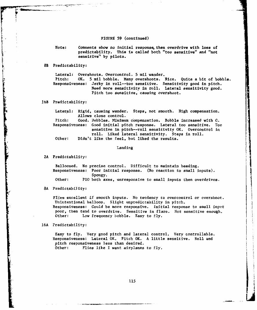
FIGURE 59 (continued)
Note: Comments show no initial response then overdrive with loss ofpredictability. This is called both "too sensitive" and "notsensitive" by pilots.
8B Predictability:
Lateral: Overshoots. Overcontrol. 5 mil wander.Pitch: OK. 5 mil bobble. Many overshoots. Nice. Quite a bit of bobble.
Responsiveness: Jerky in roll--too sensitive. Sensitivity good in pitch.Need more sensitivity in roll. Lateral sensitivity good.Pitch too sensitive, causing overshoot.
16B Predictability:
Lateral: Rigid, causing wander. Steps, not smooth. High compensation.Allows close control.
Pitch: Good. Bobbles. Minimum compensation. Bobble increased with G.Responsiveness: Good initial pitch response. Lateral too sensitive. Too
sensitive in pitch--roll sensitivity OK. Overcontrol inroll. Liked lateral sensitivity. Steps in roll.
Other: Didn't like the feel, but liked the results.
• Landing
2A Predictability:
Ld
Ballooned. No precise control. Difficult to maintain heading.Responsiveness: Poor initial response. (No reaction to small inputs).
Spongy.Other: PIO both axes, unresponsive to small inputs then overdrives.
8A Predictability:
Flies excellent if smooth inputs. No tendency to overcontrol or overshoot.Unintentional balloon. Slight unpredictability in pitch.
Responsiveness: Could be more responsive. Initial response to small inputpoor, then tend to overdrive. Sensitive in flare. Not sensitive enough.Other: Low frequency bobble. Easy to fly.
16A Predictability:
Easy to fly. Very good pitch and lateral control. Very controllable.Responsiveness: Lateral OK, Pitch OK. A little sensitive. Roll andpitch responsiveness less than desired.Other: Flies like I want airplanes to fly.
115
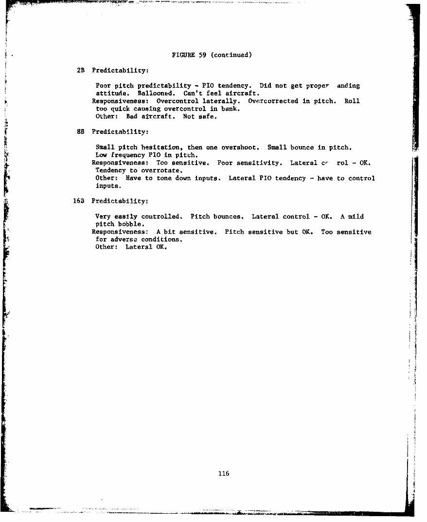
FIGURE 59 (continued)
2B Predictability:
Poor pitch predictability - PIO tendency. Did not get proper andingattitude. Ballooned. Can't feel aircraft.
Responsiveness: Overcontrol laterally. Overcorrected in pitch. Rolltoo quick causing overcontrol in bank.Other: Bad aitcraft. Not safe.
8B Predictability:
Small pitch hesitation, then one overshoot. Small bounce in pitch.Low frequency PlO in pitch.
Responsiveness: Too sensitive. Poor sensitivity. Lateral c- rol - OK.Tendency to overrotate.Other: Have to tone down inputs. Lateral PIO tendency - have to controlinputs.
16B Predictability:
Very easily controlled. Pitch bounces. Lateral control - OK. A mildpitch bobble.
Responsiveness: A bit sensitive. Pitch sensitive but OK. Too sensitivefor adverse conditions.Other: Lateral OK.
11 1
116f
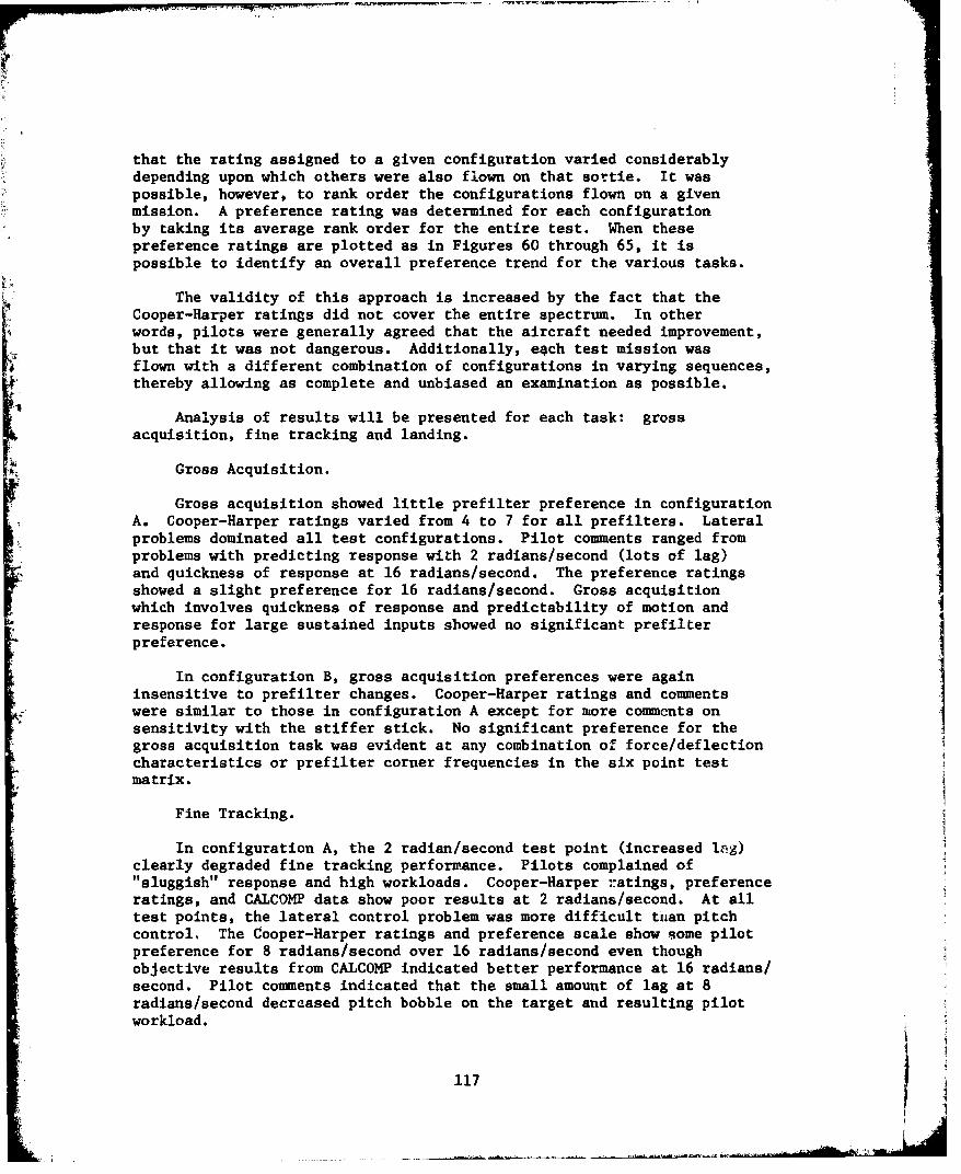
that the rating assigned to a given configuration varied considerablydepending upon which others were also flown on that sortie. It waspossible, however, to rank order the configurations flown on a givenmission. A preference rating was determined for each configurationby taking its average rank order for the entire test. When thesepreference ratings are plotted as in Figures 60 through 65, it ispossible to identify an overall preference trend for the various tasks.
The validity of this approach is increased by the fact that theCooper-Harper ratings did not cover the entire spectrum. In otherwords, pilots were generally agreed that the aircraft needed improvement,but that it was not dangerous. Additionally, each test mission wasflown with a different combination of configurations in varying sequences,
4 thereby allowing as complete and unbiased an examination as possible.
Analysis of results will be presented for each task: grossacquisition, fine tracking and landing.
Gross Acquisition.
Gross acquisition showed little prefilter preference in configuration*A. Cooper-Harper ratings varied from 4 to 7 for all prefilters. Lateral* problems dominated all test configurations. Pilot comments ranged from
problems with predicting response with 2 radians/second (lots of lag)and quickness of response at 16 radians/second. The preference ratingsshowed a slight preference for 16 radians/second. Cross acquisitionwhich involves quickness of response and predictability of motion and
response for large sustained inputs showed no significant prefilterpreference.I
In configuration B, gross acquisition preferences were again
insensitive to prefilter changes. Cooper-Harper ratings and commentswere similar to those in configuration A except for more comments on 1sensitivity with the stiffer stick. No significant preference for thegross acquisition task was evident at any combination of force/deflectioncharacteristics or prefilter corner frequencies in the six point testmatrix.
Fine Tracking.
In configuration A, the 2 radian/second test point (increased Ing)clearly degraded fine tracking performance. Pilots complained of"1sluggish" response and high workloads. Cooper-Harper ratings, preferenceratings, and CALCO1MP data show poor results at 2 radians/second. At alltest points, the lateral control problem was more difficult t'nan pitchcontrol. The C~ooper-Harper ratings and preference scale show some pilotpreference for 8 radians/second over 16 radians/second even thoughobjective results from CALCOM4P indicated better performance at 16 radians/second. Pilot comments indicated that the small amount of lag at 8radians/second decreased pitch bobble on the target and resulting pilotworkload.
117
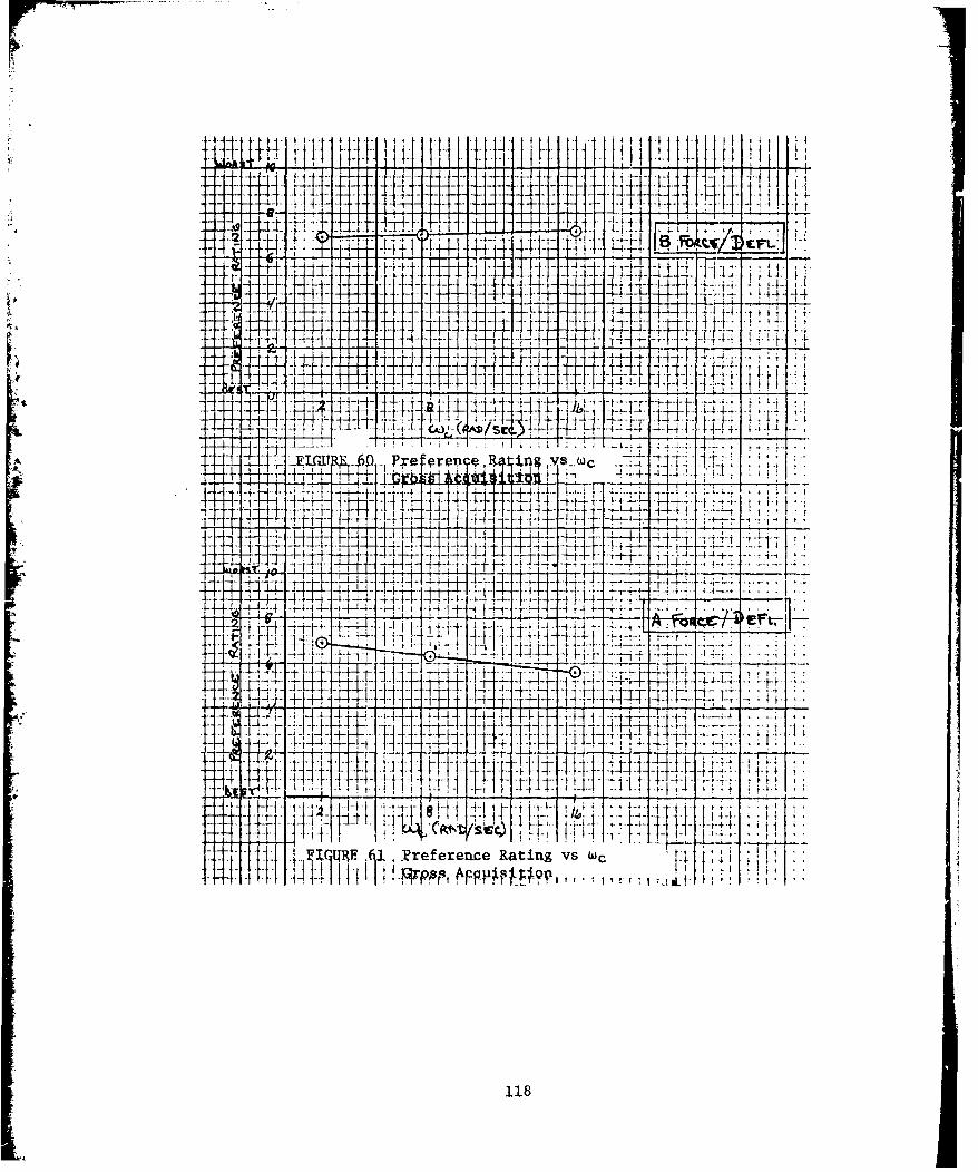
-- ~~4 -- Lj
j--
i 4 -kt-H -H -14 ---
1--
44 IT
C
_L
IM M, Ir
XC n c; ~
1184
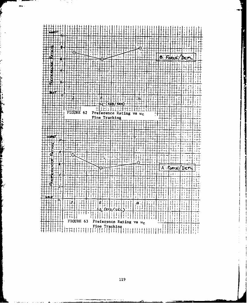
Ht i' .1-
-4-
-, T ~ ~Tj4TI1: *t h i . § L tT-t .
FIGURE 63 Preference Rating vs wT
Fine TrackingwiHjHI... -----HH~
1191
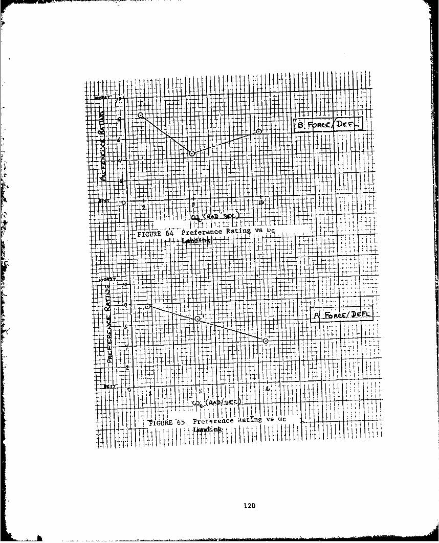
'IF
4.4
ýj tt
ILL4 %rce Rating vs u1c-FJGURýE 64 Pre ere
T+ -- 4-4
44- -r 4 I 1- 4-L
4:p -
4-ý
J4-ý
4- LAv4-H_1- it t
4: -14
T4
_77ITF 1 4
i I tT,
P
T!
ITa ng s weGIAE '65 Prefe
irM, li
120

In configuration B the 2 radian/second prefilter produced widelyvarying results. Cooper-Harper ratings varied from 4 to 7. Pilotcomments varied from praise of the results to complaints. A high work-load when actually achieving reasonable tracking results was evident.Actual performance as measured by CALCOMP also varied wi,4ely from someof the best tracking in configuration B to some of the worst. With thehigh amount of lag, the configuration was apparently sensitive to changesin pilot inputs, whether due to atmospheric conditions, pilot fatigue, orsome change in individual gain or time constant. It is obvious thatalthough the average performance and ratings at 2 radians/second compareswell to other prefilter test points in configuration B, the extremevariabillty of pilot evaluations makes this high sensitivity/high lagcombination less desirable.
Objective CALCOMP data indicates that 16 radians/second in con-figuration B was best. Preference ratings showed a preference for 8radians/second. Cooper-Harper ratings indicafte a slight preference at16 radians/second. As with configuration A pilots liked the responsivenessof 16 radians/second but also liked the decreased pitch bobble arzidecreased pilot workload provided with 8 radians/second.
Overall, 8 radians/second wais slightly preferred by the pilots forfine tracking in both configuration A and configuration B even though16 radians/second provided better' performance.
In all of the air-to-air tasks, azimuth errors proved to be the largestproblem (see Figure 66). Typically, pilots complained of an inability to
get in the plane of motion of the target resulting in a large amplitude.Ilow frequency azimuth wander (Figure 66). Pilots sometimes felt that thelateral tracking problem was so great that it prohibited a fair evaluationof the pitch response, especially in lazy eight maneuvers. Occasionally,
configurations with rather poor pitch characteristics were given relatively
is particularly apparent in configuration 2B, where the sensitivity of theB stick force/deflection configuration allowed the pilot to "manhandle" thelateral axis to an improved, but still poor, azimuth solution.
The magnitude of this problem is evident in the pilot ratings for theair-to-air tasks. Even the previously determined optimum configuration(reference 3), 16A, received Cooper-Harper ratings in the 4 to 3,"deficiencies warrant improvement", range. Tracking performanice (Figure 67)confirms the imprecise tracking in all configurations despite the high levelof experience of the test team pilots (Figure 68). Pilot ratings andperformance data suggest that the azimuth error problem may have maskedmore subtle handling qualities variations with changes in the prefilter.
Analysis of magnetic tape data showed that during steady curns, theN~T-33A maintained a residual sideslip angle (approximately one degree or17 mils). This is what prevented the pilots from maintaining the pipper on
the target in azimuth while staying in the target's plane. Therefore, it isrecommended that the residual sideslip in steady turns be eliminated priorIto further handling qualiti~es during tracking testing ia the NT-33A.
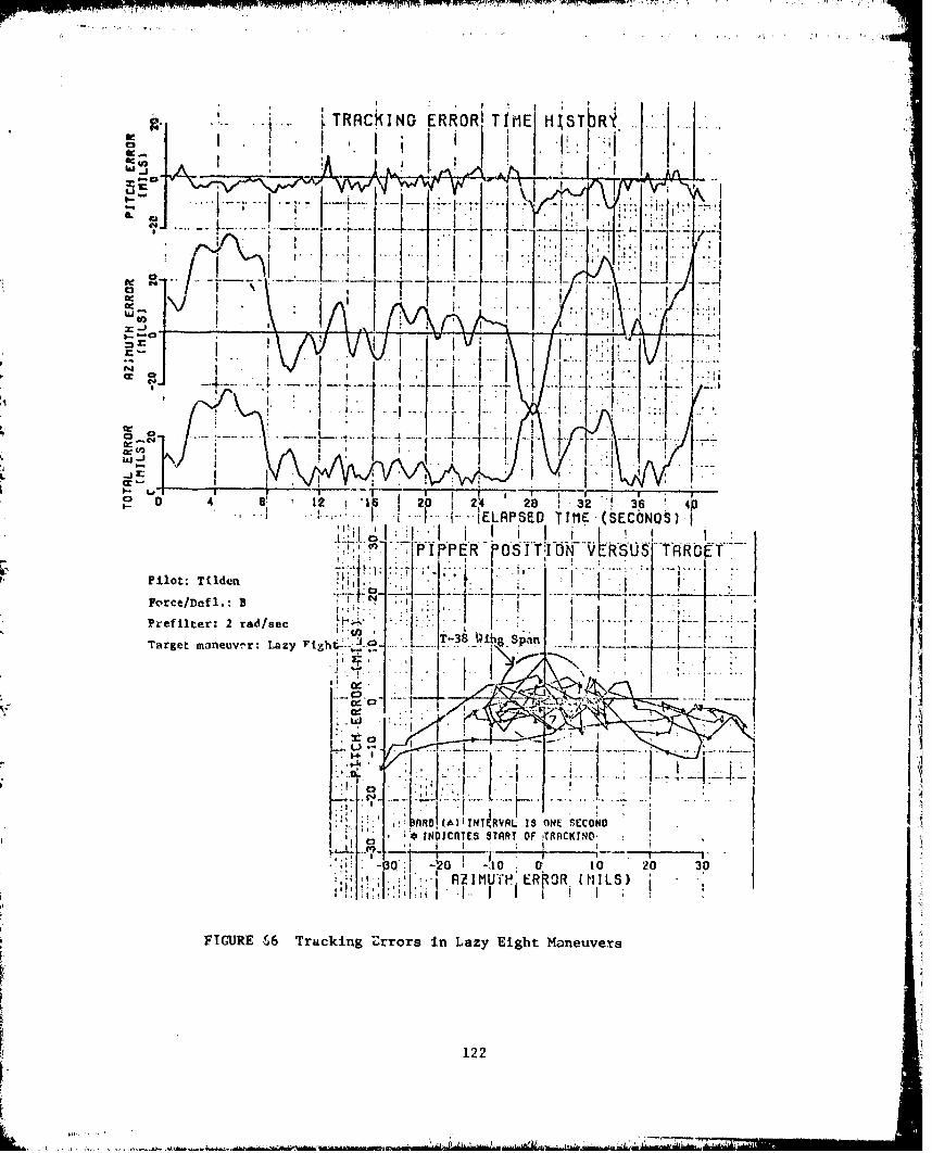
A. j...~.TRACKING ROR O1E HiýVbR~i
IL
JJA
I0T1. 0 42 1 24 28 32 36 ]
p E 51:1 0Pilot:Tilde
,.-. -o,Icre/e l.: B17
(AhiELAPSD 13 ONE (SECOND S
TPIESSTRT fOF !TiOR~sT~F"
T11er I10 01 1 t7.ZIM11ii F.C (ISTarget f)6uv~r Truy cki ng Zrr s in L az T-3ht Ma eu er
- .- i.-122

.40
77* 110
A FO~I D( ) POC. A.
'.1 IN" 1 a
FIGRE67Trakn Eror inCntn FndWn-pTaManeuvers
I. .123
roa.... .
~AD
h4)ii ±wo/get
I 4I
Of
FIGURE 67 (cont) Tracking Errors in Constant a and
Wind-Up-Turn Maneuvers
124

-J
FIGURE 68 PILOT BACKGROUND INFORMATION
PILOT A:
Capt G. V. LewisF-4(C/D/E)--950 hours, SEA combat tourMission: Air-to-air and air-to-groundT-38--200 hoursMission: Photo/Safety Chase
PILOT B:
Capt C.V. TildenF-4(C/D/E)--2300 hours (700 hours IP), SEA combat tourMission: Air-to-air and air-tQ-groundPrevious Navigator, 2000 hours C-130E, Light Aircraft
PILOT C:
Capt M. ShmulFuga-Magistar--900 hours (650 hours IP)Mirage, KFIR--2000 hours, Middle East Combat Experience since 1966Mission: Air-to-air and air-to-groundExecutive jet, light transport, light aircraft--300 hours
125
L. . .... .. ... .. . ... 1J

Landing.
"The landing task showed the clearest contrast in pilot preferencewith changes in prefilter.
In configuration A, 16 radians/second was clearly preferred. Notethat 8 radian/second has been used in all previous tests in the landingconfiguration. The preference ratings indicated a strong preference for16 radians/second. Comments indicated that as lag increased the aircraftwas not responsive enough initially, then the pilot would overdrive hisinput resulting in poor predictability.
With configuration B, the more sensitive deflection characteristics,a slight shift in preference was evident. Configuration B was lessdesirable than A. At 2 radians/second, characteristics of overdrivingand unpredictability were again evident but the sensitivity made thistest combination close to uncontrollable. However, 8 radians/second wasa clear preference on the preference ratings and compared well to 16radians/second on the Cocper-Harper ratings. Although 8 radians/secondwas preferred, no change'in prefilter within the range tested wouldimprove pilot evaluations of donfiguration B to match configuration A.The additional lag at 8 radians/second had slightly improved thecharacteristics of configuration B but not as much as just flying withconfiguration A.
Future Tests.
Generally, pilots preferred more lateral sensitivity and less pitchsensitivity for air-to-air tasks. This may have been due to the lateralcharacteristics of the NT-33A and/or the physical characteristics ofsidestick controlled aircraft. It is recommeided that future tests ofsidestick controller characteristics evaluate variations in control harmonybetween the pitch and roll axis.
CONTROL HARMONY
Although it was not part of the original test objectives, a very limitedinvestigation of control harmony was conducted during the test. On five ofthe nineteen test sorties, one evaluation of a stiff, sensitive lateral andnominal pitch sensitivity stick was conducted. This configuration was:
Axis Force Deflection Prefilter (w )
Pitch .167 g/lb .7 deg/ib 2.5 rad/sec
Lateral 7 deg/sec/lb .3 deg/lb 16 rad/sec
12t
Air-to-Air Tasks.
Three evaluations, one by each project pilot, were conducted for grossacquisition and fine tracking. During these flights, all three pilotsconsidered it to be the best configuration for both gross acquisition andfine tracking, as compared to the other configurations seen on that flight(2B and 8A in all three cases).
From limited HQDT Calcomp plots, the average R.M.S. errors for finetracking in constant g and wind-up turns are:
Pitch - 3.62 mils
Azimuth - 9.04 mils
Total - 9.82 mils
A comparison of these errors to those shown in Figure 67 do notindicate a marked improvement. However, when examining the lazy-eightmaneuver, it is found that the performance was dramatically improved.Figure 69 shows a Calcomp plot for the best tracking during lazy-eigbtsfor any of the original test configurations. Figure 70 shows the oalylazy-eight recorded on film with the mixed harmony configuration.
Pilot comments indicate that this was the best performing configuration.
However, two of the three pilots complained about the control harmony andespecially about the jerkiness in roll.
Landing.
Two landings were made in this configuration. In the landing task,this configuration was not optimum. While no comments were made concerningcontrol harmony, it was mentioned that there was not enough pitch respon-siveness, while the lateral sensitivity was okay. Cooper-Harper ratingswere 5 and 5.5, which are well below the ratings given for configurations16A and 8B.
CONCLUSIONS AND RECON14ENDATIONS
The specific objectives of the NT-33A test were to determine thepreferred first order prefilter for a given force/deflection configurationand to determine the variation of prefilter preference with force/deflectionchanges. Overall analysis of the results show that there was anidentifiable preference for a prefilter for two out of the three tasksevaluated, and that this preference changed when the stick force/deflectionwas changed.
More specifically, in the gross acquisition task, pilots indicatedlittle preference for one prefilter over another in both configurationsA and B.
127
S.... 4 -.. ;•'L.. - : "- - • • •s•::- I .. • .. • L • -•IJ-•...... .. . .. . .... •• • !° ° • -- :1
TRCIG R IT ME -MS1RT go -G'RUH'.~..1
4:1 I:
I E .E IND
03peilo unrsm ZEW
- I-
* f I
"NO jjf i
~~~v " !~.t~:~aA~z OF INDI TRACS$11Nd or ~ t uprX100! I l' ! j~ .0 eTP IN A
011 1;...... 0. f1 0 0 1 0 7o2L-,I 0 L L . S A!?. 210 SANK hi T00:ER OREW (M UIOLS) N
-1 77 h '~IHCINU0E al 220A I NdT k7- 7I 7kF~ TSAN. C1?IE9t OCPRLSOI NTC T IHl
3I1 KN E ONUMSERRO , 10-TS. .I PLS O FI T v, 4000.TAIIN R F I.;: '- o Or A IC DE L.~~~lii4 mI fl* 31.3::. :b -i mmsi" Atmm NEITCH I .16316 A L 1 5 N IL
L I 08~~~t0UTH W b, act Dro0K I TunoRI.Ht I S S t S
I ., RIKN iU LRTE22.7 SEONDS.L1EM FIL SE''3. AT- 4.0 FRANC ?tot S9 W .
II I fit ' ,1i:wuPOSt or0007 FIL S I PME* 1 AND LAE IIA. PEOICN* ITs .PE WISH
FIGURE 69m trackin Resultsl."Alot
7 7 7 CAL OA.-
sm PCPINK 'Im"ERON 128 ~
ii :4. .II,. ..9
TRACKINO--IRRORI.T KE HI~STO MY HOD N
I V~~~iii i-i II
EAPS0Th
N. IRCKNDERROR:0 '1 ON I P P OIT V SU
InTL0OAf1w. OF ImisiAS eR0SWILMT 0133 U1H14 .
01)11191ttlo F l ear)1
I el
31 a : ,* 1
:A J. i -0 0 I 1 0 3
b ~ ~ ~ * 1' ' I* ; i: rLIO IM N it LIIAHI arpt.a JUNo:' .ZI NO ; ~ c &W,~Ali ~i 10 0.1 03JR IB ~ ) 2 3 IH ;1; V. ~A M P~s 00 FCC OR! (MjiI1CWLS o
j!~INNti 33 111 II ~JC4q*)CHOU0 d dFWTAL.5 - 'OU'R I WldAN'SMM~
OLtIG ON I CSCL 0 .NI.II R~* 11.111.
1 00 f [[I Oi.l;t-AtSl'uICRA ANHTRFC N EROS(qOL IgMUP4f 310 .~ 0WWC COIK tON NI).;: ;i; d i 1 d W , r r i -2' .: S I C :iZA . AM C
FIGUREK. 70 Trckn Results
Ito iL a %1!4. NOME ýCR mov;:4 TI ~f orFll rp~k129r
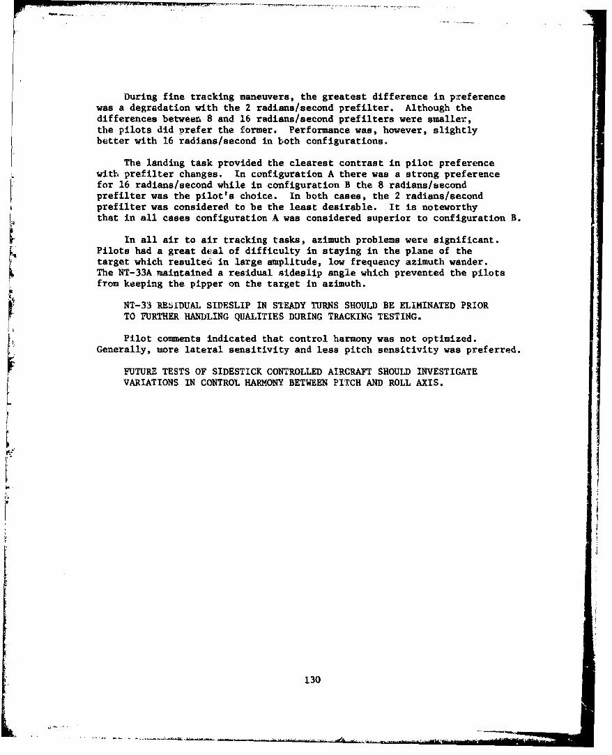
During fine tracking maneuvers, the greatest difference in preferencewas a degradation with the 2 radians/second prefiliter. Although thedifferences between 8 and 16 radians/second prefiliters were smaller,the pilots did porefer the former. Performance was, however, slightlybetter with 16 radians/second in both configurations.
The landing task provided the clearest contrast in pilot preferencewith prefiliter changes. In configuration A there was a strong preferencefor 16 radians/second while in configuration B the 8 radians/secondprefilter was the pilot's choice. In both cases, the 2 radians/secondprefiliter was considered to be the least desirable. It is noteworthythat in all cases configuration A was considered superior to configuration B.
In all air to air tracking tasks, azimuth problems were significant.Pilots had a great dcal of difficulty in staying in the plane of thetarget which resulte6 in large amplitude, low frequenacy azimuth wander.The NT-33A maintained a residual sideslip angle which prevented the pilotsfrom keeping the pipper on the target in azimuth.
NT-33 RE~jIDUAL SIDESLIP IN STEADY TURNS SHOULD BE ELIMINATED PRI.ORTO FURTHER HANDLING QUALITIES DURING TRACKING TESTING.
Pilot coumments indicated that control harmony was not optimized.Generally, more lateral sensitivity and less pitch sensitivity was preferred.
FUTURE TESTS OF SIDESTICK CONTROLLED AIRCRAFT SHOULD INVESTIGATEVARIATIONS IN CONTROL HARMONY BETWEEN PITCH AND ROLL AXIS.
130
APPENDIX E
TECHNICAL RESULTS AND DISCUSSION FROM USAF TEST PILOT SCHOOL
LETTER REPORT - 6 December 1978 "Limited Flight Evaluation of the
Effect of Modal Dynamics Variations on the Handling Qualities of
Sidestick Controlled Aircraft" by W.W. Copeland, LCDR, USN;
J.R. Anderson, Captain, USAF; R.T. Banholzer, Captain, USAF;
M. Dvir, Major, IAF; C.R. Jones, Captain, USAF and L.R. Perlee,
Captain, USAF.
ABSTRACT
A limited investigation was conducted to determine the effect of
modal dynamic variations on the handling qualities of sidestick controlled
aircraft. The test aircraft, AFFDL's variable stability NT-33A, was
configured with one of five sets of aircraft dynamics, one sidestick
deflection gradient, and one of two sets of stick force response
characteristics, and was then evaluated through a well defined series of
air-to-air tracking tasks. Pilot comments, tracking performance, and
Cooper-Harper ratings were analyzed for all configurations.
The test results for all tracking tasks show a pilot preference for
the baseline (medium) short-period frequency dynamics given a heavyIsidestick force response, and the low short-period frequency dynamics
given a light sidestick force response. Pilot preference for the base-
line (medium) roll mode time constant was independent of sidestick force
preference for the sidestick force response characteristic was a function
of the dynamics and the air-to-air tracking maneuver.
A total of 45 calibration, data, target support, and practice sorties
totalling 63.0 hours were flown at the Air Force Flight Test Center,
Edwards AFB, California from 27 October 1978 to 27 November 1978.
131
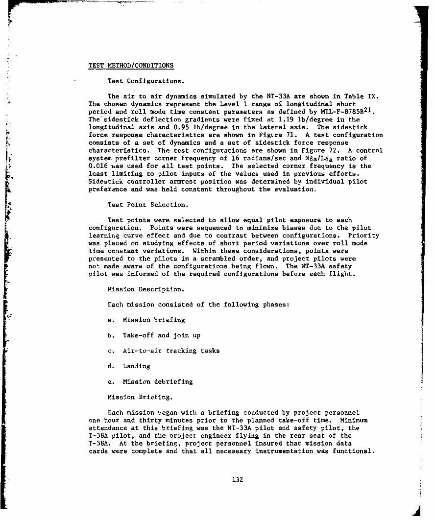
TEST METHOD/CONDITIONS
Test Configurations.
The air to air dynamics simulated by the NT-33A are shown in Table IX.The chosen dynamics represent the Level 1 range of longitudinal shortperiod and roll mode time constant parameters as defined by MIL-F-8785B 2 1 .The sidestick deflection gradients were fixed at 1.19 lb/degree in thelongitudinal axis and 0.95 lb/degree in the lateral axis. The sidestickforce response characteristics are shown in Figure 71. A test configurationconsists of a set of dynamics and a set of sidestick force responsecharacteristics. The test configurations are shown in Figure 72. A controlsystem prefilter corner frequency of 16 radians/sec and NSa/L6a ratio of0.016 was used for all test points. The selected corner frequency is theleast limiting to pilot inputs of the values used in previous efforts.Sidestick controller armrest position was determined by individual pilotpreference and was held constant throughout the evaluation.
Test Point Selection.
Test points were selected to allow equal pilot exposure to eachconfiguration. Points were sequenced to minimize biases due to the pilotlearning curve effect and due to contrast between configurations. Prioritywas placed on studying effects of short period variations over roll modetime constant variations. Within these considerations, points werepresented to the pilots in a scrambled order, and project pilots were
n not made aware of the configurations being flown. The NT-33A safetypilot was informed of the required configurations before each flight.
Mission Description.
Each mission consisted of the following phases:
a. Mission briefing
b. Take-off and join up
c. Air-to-air tracking tasks
d. Landing
e. Mission debriefing
Mission Briefing.
Each mission began with a briefing conducted by project personnelone hour and thirty minutes prior to the planned take-off time. Minimumattendance at this briefing was the NT-33A pilot and safety pilot, theT-38A pilot, and the project engineer flying in the rear seat of theT-38A. At the briefing, project personnel insured that mission datacards were complete and that all necessary instrumentation was functional.
132
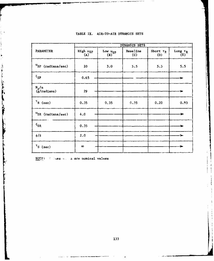
TABLE IX. AIR-TO-AIR DYNAMICS SETS
DYNAMICS SETS .....
PARAMETER High wSp Low 4SP Baseline Short TR Long TR(A) (B) (C) (D) (E)
WSP (radians/sec) 10 3.0 5.5 5.3 5.5
SP 0.65 "-
Nz/a(g/radians) 29 --
TR (sec) 0.35 0.35 0.35 0.20 0.95
wDR (radians/sec) 4.0 -
DR 0.35 -
2.0 -
TS (sec) 0o -I
NOTF :ý',es -, a are nominal values
133
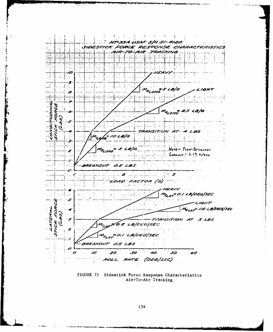
. .......... .
IN1
i 7, 1lS7 V A ---.---..- -- 4&
-N llp A6 IA
UP 4 -. F itc4-- -rawm
7WAMS/ Z. &/I 7-C LSVYC
4_ 9
fO Ave
2 '4= ~m-n-
FIGUE 71Sidstic Foce Rspose Carateritic
- -2-To-AOr Tracking
134C/Tr
---------- .....

NIP
.. I.
• ..... j... ~l• •...
I~i
sI __E-<4•'_",.,• - .S_••
iN
IN
~7Y,
~ 44
1/12-/S--7 H11
I135

Take-off and Join-Up.
After engine start, the NT-33A pilot performed a control sweep andrecorded it on magnetic tape. AFFRC Manual 55-2 formation taxi, "lastchance", takeoff, and join up procedures were used. Following join up,The T-38A pilot took the lead and proceeded to 13,000 feet MSL in thetest area. During the climb, the NT-33A pilot maintained route formationusing basic T-33 dynamics and sidestick controller characteristics.
Air-to-Air Tasks.
The air-to-air tasks were performed as described below. Eachmaneuver was performed twice, once in each direction. Both aircraftreturned to base at the completion of the air-to-air testing.
Mission Debriefing.
The NT-33A pilot handcarried the magnetic tape, audio tape and guncamera magazines to the debriefing. Each mission ended with a debriefingincluding the NT-33A pilot and safety pilot, the T-38A pilot, and theproject engineer.
Air-to-Air Tasks.
The air-to-air tasks began with Lhe NT-33A trimmed for level flightat 13,000 feet pressure altitude and 300 KIPS. The NT-33A was notretrlmmed during the tasks. The tasks were performed without using therudder (i.e., feet on the floor) and with a fixed gunsight depressionof 55 mils.
Gross acquisition task. The NT-33A pilot aggressively placed thepipper on the T-38A tailpipe junction. When the pipper was held withinfive mils of the tailpipe junction, fine tracking started. This taskwas evaluated using maneuver #1 below.
Maneuver #1. The NT-33A pilot established 1500 feet separation asthe T-38A pilot initiated a 2g, 300 KIAS, level turn. The NT-33A pilotcalled "tracking" when fine tracking began. After 10 seconds of tracking,the T-38A pilot performed an unloaded level reversal, using half stickdeflection, to a 2g, 300 KIAS, level turn in the opposite direction. TheNT-33A pilot waited until the T-38A crossed the canopy bow prior tomaneuvering, called "hack", and aggressively maneuvered to reacquire theT-38A and start fine tracking. The NT-33A pilot called "tracking" whengross acquisition ended and fine tracking commenced. After 15 seconds offine tracking, an additional reversal sequence was accomplished. TheT-38A pilot called "knock it off" 15 seconds after the last "tracking"call. Both aircraft were thcn rolled wings level.
136
Fine tracking task. The NT-33A pilot precisely and assiduously
kept the pipper centered on the T-38A tailpipe junction. This taskwas evaluated using Maneuvers #2 and #3 below.
Maneuver #2. The NT-33A pilot established 1500 feet separationfrom the T-38A with both aircraft in a 10 degree bank, 300 KIAS,level turn. When the NT-33A pilot called "tracking", the T-38A pilotinitiated a wind-up turn from lg to 3.Og at 0.2g per second at aconstant 300 KIAS. Ten seconds after the T-38A reached 3.0g, the T-38Apilot called "knock it off". Both aircraft were then rolled wings level.The NT-33A pilot then paused to record additional comments prior tobeginning maneuver #3.
Maneuver #3. After the NT-33A pilot estatlished 1500 feet separation,the T-38A pilot initiated a 2g, 300 KIAS, level turn. The NT-33A pilotcalled "tracking" when fine tracking began. After 10 seconds of level
tracking, the T-38A pilot reversed the turn at 10 degrees per second ofroll, maintaining 2g, and returned to a 2g, level turn. The NT-33A pilotcontinued fine tracking throughout the reversal and level turn. Bothaircraft pilots accepted the resulting airspeed loss during the reversaland did not attempt to maintain 300 KIAS throughout the maneuver. After10 seconds of level turn, the T-38A ?ilot called "knock it off". Afterthe "knock it off" call, both aircraft were rolled wings level.
Following the completion of each task, the NT-33A pilot recordedadditional comments and completed the inflight comment card. After bothtasks were completed, open loop records were taken, and then the NT-33Awas configured for the next test point. The above sequence was repeatedfor each air-to-air test point. During the maneuvers, the NT-33A pilotattempted to maintain 1500 iet separation, but at no time allowed theseparation to decrease to less than 1000 feet. The NT-33A magnetic tapesystem, audio recorder, and gun camera was rurt during each task.
ITEST RESULTS
Pilot comments and Cooper-Harper ratings were provided for each maneuverand test configuration flown. Condensed pilot comments are contained inFigure 73, and a summary of Cooper-Harper ratings, compiled by pilot,flight number, maneuver, dynamics set and sidestick force responsecharacteristic, is provided in Table X. On several flights, oveTall Cooper-Harper ratings of a test configuration were given and are also included.
Since the range of Cooper-Harper ratings given by each pilot differednotice bly, a ranking scheme was used to aid in analysis. For each of thethree m neuvers, individual pilot Cooper-Harper ratings were rank orderedand assigned an integer ranking with the integer 1 corresponding to thepilot's best Cooper-Harper rating. In the case of ties, the midrank methodwas used. The rankings for a given test configuration were then averaged
137
FIGURE 73 CONDENSED PILOT COMENTS
NOTE: See Figure72 for explanation of test configuration codes.
Configuration AH:
Maneuver 1: non-oscillatory in both axes; control harmony satisfactorywith longitudinal force slightly higher than lateral force. C.H. 4,4,5
Maneuver 2: longitudinal and lateral force too high; slight pitchbobble which decreased under increasing g. C.H. 4,4,6
Maneuver 3: lateral control was imprecise under g load while rolling;stick forces are too high in both axes. C.H. 4,5,5
Configuration AL:
Maneuver 1: too fast of a longitudinal response; too oscillatory;
imprecise; longitudinal axis too sensitive. C.H. 4,5,6Maneuver 2: longitudinal response is too fast, oscillatory, imprecise;
above two g's less oscillatory; control harmony poor-too sensitivelongitudinally. C.H. 5,5,4
Maneuver 3: same comments as Maneuver #2. C.H. 4,3,5.5
Configuration :I'H:
Maneuver 1: longitudinal stick forces are too heavy; control harmonyis good; slow response in both axes; more precise longitudinally thanlaterally. C.H. 3,6,5
Maneuver 2: longitudinal axis the best; high longitudinal stick forcehigh pifot workload. C.H. 4,4,6
Maneuver 3: sluggish response longitudinally, however it is precise andnon-oscillatory; lateral axis is imprecise; moderate lateral pilot compensation;control harmony unsatisfactory. C.H. 4,4,4.5
Configuration BL:
Maneuver 1: longitudinal axis very good with a slightly slow initialresponse, imprecise lateral axis. C.H. 3,3,5
Maneuver 2: excellent longitudinal response; slight problem making smallcorrections laterally. C.H. 2,2,4
Maneuver 3: excellent longitudinal response; slight lateral imprecisionS~during rolling portion of cine--track maneuver. C.H. 2,2,5
Configuration CH:
Significant discrepancy exists; two of the four evaluations were consideredgood, two were poor; within each evaluation comments and ratings were inagreement; during the poor evaluations, unexplainable sideslip oscillationswere present for the same open loop dynamics - reason(s) remain unknown.
138
FIGURE 73 (continued)
Configuration CL:
Maneuver 1: initial longitudinal reaponse is good; precise, but somepitch bobble; lateral overshoot when trying to stop pipper on target. Thiscaused the discrepancy in CH. ratings; two pilots talking about stoppingthe pipper, the other on the dynamic motion. C.H. 3,3,6*
Maneuver2: high frequency small oscillation in the longitudinal axis;imprecise laterally due to low frequency oscillation; minimum pilot compensationnecessary; good aircraft. C.H. 3.3,6*
Maneuver 3: some longitudinal characteristics; good pitch control;lateral axis more imprecise, tendency for a slight lateral PIO; still agood configuration. C.H. 3,4,6*
*The identical difficulties encountered with configuration (CH) were experiencedby Pilot C during one evaluation; the comments noted above for each maneuverwere those for Pilots B and D.
Configuration DH:
Maneuver 1: good gross acquisition in both axes; very slightlongitudinal oscillation. C.H. 2,4
Maneuver 2: longitudinal force slightly higher than lateral force:lateral axis more sensitive than longitudinal axia. C.H. 2,4
Maneuver 3: good longitudinally; oscillatory laterally; tend toovercontrol laterally; control harmony unsatisfactory - lateral force toohigh. C.H. 4,4
Configuration DL:
Maneuver 1: very good response longitudinally, precise; laterallytoo sensitive to small inputs; roll ratchet; control harmony poor - heavylongitudinally, light laterally. C.H. 4
Maneuver 2: same as #1; sensitive laterally below two g's, betterabove two g's; longitudinal stick force per g - good. C.H. 4
Maneuver 3: very precise longitudinally; laterally imprecise and theforces are too light; control harmony is bad- heavy longitudinally; lightlaterally. C.H. 4
Configuration El:
Maneuver 1: very sluggish lateral response, over correction constantly;PIO tendency laterally; control harmony unsatisfactory. C.H. 7,7
Maneuver 2: high stick forces both axes; laterally sluggish andimprecise under g. C.H. 7,7
Maneuver 3: same as #2; big difference between axes. C.H. 7,7
139
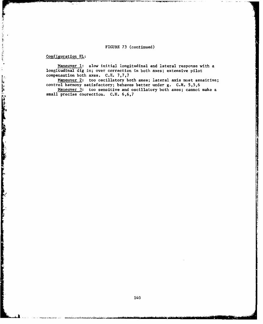
FIGURE 73 (continued)
Configuration EL:
Maneuver 1: slow initial longitudinal and lateral response with alongitudinal dig in; over correction in both axes; extensive pilotcompensation both axes. C.H. 7,7,7
Maneuver 2: too oscillatory both axes; lateral axis most sensitive;control harmony satisfactory; behaves better under g. C.H. 5,5,6
Maneuver 3: too sensitive and oscillatory both axes; cannot make asmall precise coorection. C.H. 6,6,7
140
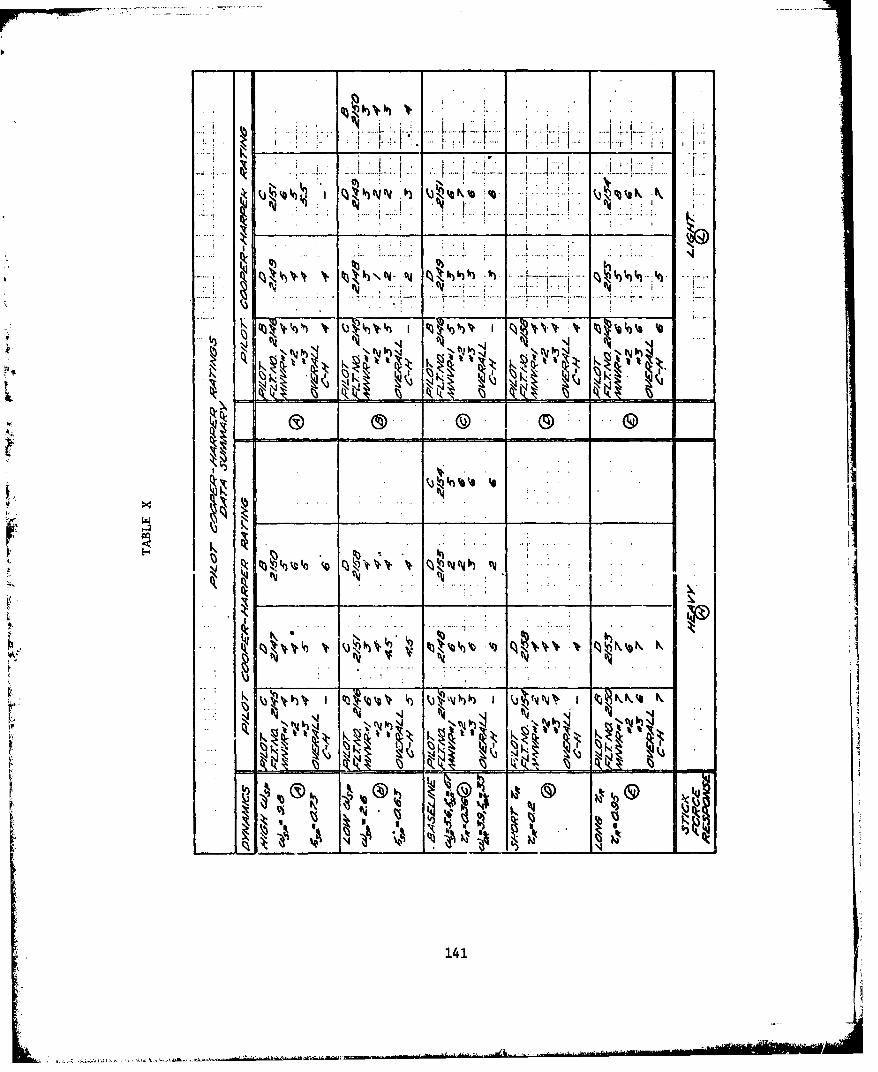
I i -.. ii I 1 I
. I -...... ... ......
-" I; '- . ... -! .• .! ,.1! . , .
. .... ... . .
I I k
t4 tq ttJ cJy
' !
'4J 4
~• •
'~ .. J .. . . .. . .!
114
4... ....A'... . " '....41
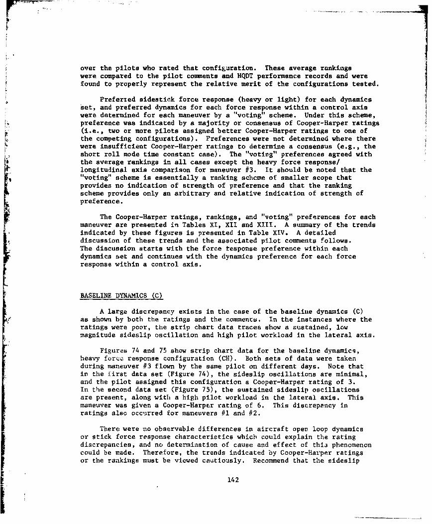
over the pilots who rated that configuration. These average rankingswere compared to the pilot conmments and HQDT performance records and werefound to properly represent the relative merit of the configurations tested.
Preferred sidestick force response (heavy or light) for each dynamicsset, and preferred dynamics for each force response within a control axiswere determined for each maneuver by a "voting" scheme. Under this scheme,preference was indicated by a majority or consensus of Cooper-Harper ratings(i.e., two or more pilots assigned better Cooper-Harper ratings to one ofthe competing configurations). Preferences were not determined where therewere insufficient Cooper-Harper ratings to determine a consensus (e.g., theJshort roll mode time constant case). The "votir~g" preferences agreed withthe average rankings in all cases except the heavy force response/longitudinal axis comparison for maneuver #3. It should be noted that the"1voting" scheme is essentially a ranking schcme of smaller scope thatprovides no indication of strength of preference and that the rankingscheme provides only an arbitrary and relative indication of strength ofpreference.
The Cooper-Harper ratings, rankings, and "voting" preferences for eachmaneuver are presented in Tables XI, XII and XIII. A summary of the trendsindicated by these figures is presented in Table XIV. A detaileddiscussion of these trends and the associated pilot comments follows.
The discussion starts with the force tesponse preference within eachdynamics set and continues with the dynamics preference for each force
BASELINE DYNAMICS (C)
A large discrepancy exists in the case of the baselitie dynamics (C)as shown by both the ratings and the comments. In the instances where theratings were poor, the strip chart data traces show a sustained, lowmagnitude sideslip oscillation and high pilot workload in the lateral axis.
Figures 74 and 75 show strip chart data for the baseline dynamics,heavy force~ response configuration (CHI). Both sets of data were takenduring maneuver #3 flown by the same pilot on different days. Note thatin~ the first data set (Figure 74), the sideslip oscillations are minimal,and the pilot assigned this configuration a Cooper-Harper rating of 3.In the second data set (Figure 75), the sustained sideslip oscillationsare present, along with a high pilot workload in the lateral axis. Thismaneuver was given a Cooper-Harper rating of 6. This discrepency inratings also occuirred for maneuvers #1 and #2.
There were no observable differences in aircraft open loop dynamicsor stick force response characteristics which could explain the ratingdiscrepancies, and no determination of cause and effect of this phenomenoncould be made. Therefore, the trends indicated by Cooper-Harper ratingsor the rankings must be viewed cautiously. Recommend that the sideslip
142
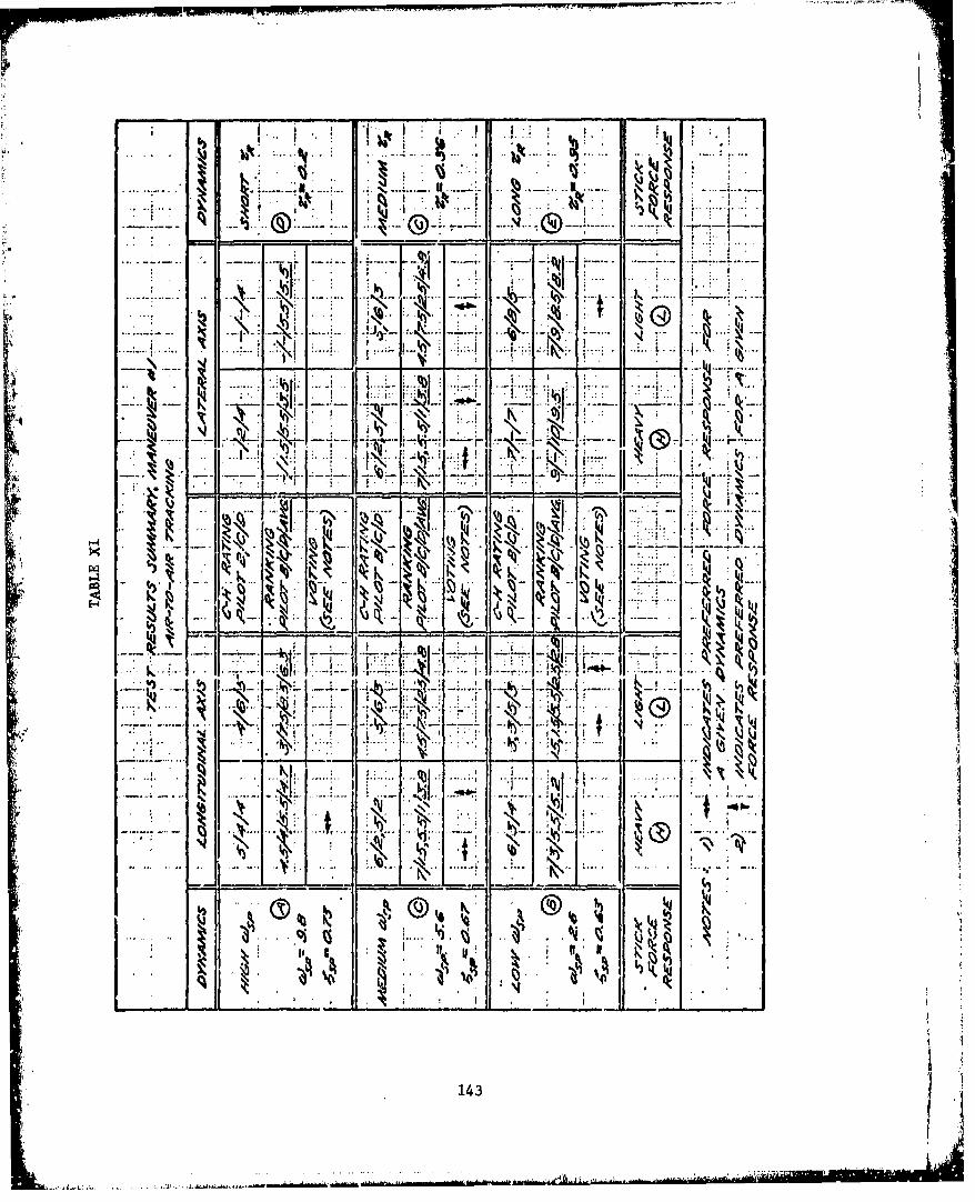
-IV
N
.77.
K~ 14
....... I kxf
I... ILK., .
A. i
lo C ~
143 1
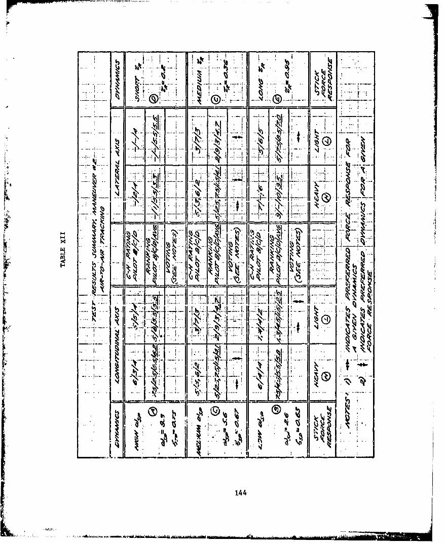
K.
• • • " I" .' •" ' "I "1* >j:~ . : J' . . h .• .I-... .. K. • ; :. , .•.. -:-. ..
-77.
S... .. . , -N'i ; .- , :': I: i . .- : •. ' t •
"M g
• . --- ... - .--•--. -- -' . -.... .- - .... • I .-- .. -. • . . . .. . . • - .
\.. ... ...
~ x I ýk.
NN
144
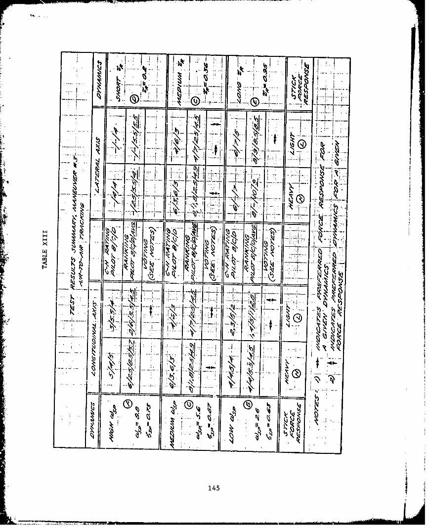
__ I .. . It .: ....- --.... '+ - ...... _- ,_.._..._.- ...... -.., .. .. ._.
---- ---- ---
.-~ •-1-' ': ."-,- '- --- •'-' •i' x
. -,(J+ . I • • -. I '_•- . ".. . " '
.. 4. .1 . .*"
_ ' ,, , -
.
'1-•- .- J -,
.. .I .-..... •I:V 7 +. .. : .• . •Kv t ___+ "• 't(A' '34.
•~ ~~~~~ N••.• •: • +,
- . ... I... .. ' * -- ,
S®. ,+145
145

TABLE XIV
PILOT PREFERENCE - TREND SUMMARY
COMPARISON BASE PREFERENCE
DYNAMICS SET SIDESTICK FORCE RESPONSE
High w SP (A) Heavy (H) - Gross Acquisition
Light (L) - Fine Tracking
Low w SP (B) Light (L)
Baseline (C) Heavy (H) - Gross Acquisition
No preference - Fine Tracking
Short TR (D) (Insufficient Data)
Long TR (E) Light (L)
SIDESTICK FORCE RESPONSE LONGITUDINAL LATERALDYNAMICS DYNAMICS
Heavy (H) Base'ine (C) Baseline (C)
Light (L) Low w (B) Baseline (C)
NOTE: Preferences the same for both tasks except as stated.
146
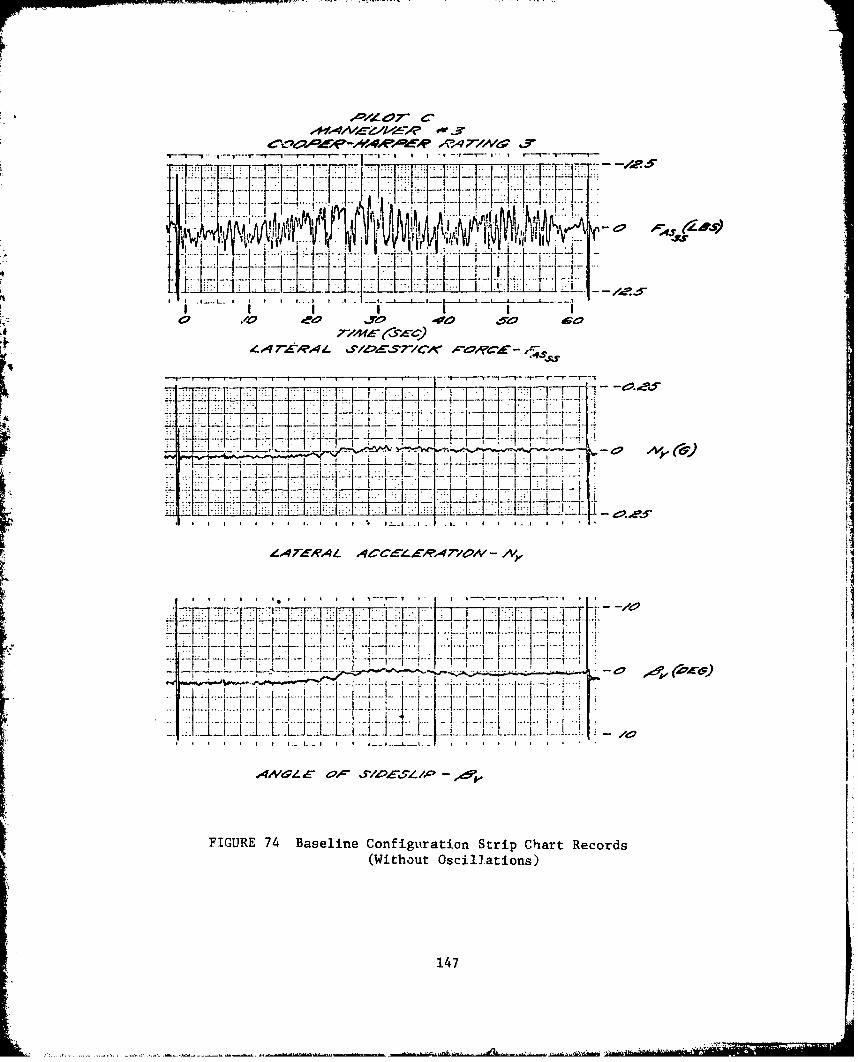
1- I - - 1
T~7~ i ~.. I1lt .-5
4 o 7470ý.4 %5'Z~E'T71C4C 1C"4 tJOA.Idxf A{
__ ii _ i A
Z.4 r--AL 4~~~rC-~.
.4J.
4M9. 0I- Ir/AzL-T4
FIUEJ4Baein Cofgrtio{] StiCat Rcod~(Without Oscpillaions)
:1: ~ T 147
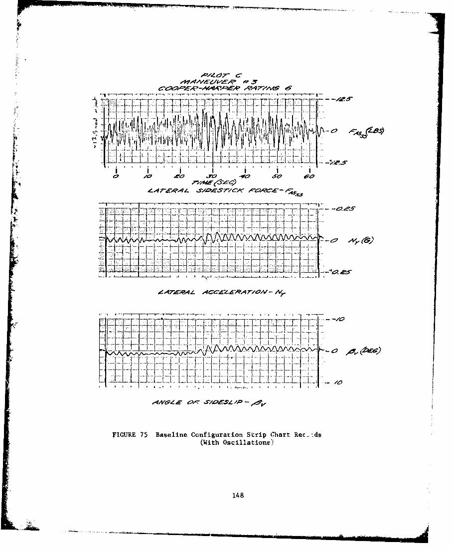
-A
0/0 2W0 _A0 040 6
111± L77L _40
FIUR 75 B seln Ccfgrto Stri Chr R I- .-±-d -
eA7-A(With Oscillq4/ations
- - # TV - ]Ifii7V~148 tT~ /

oscillation problem be explored and resolved prior to any further testing.Recommend that further testing with baseline dynamics be conducted toprovide an adequate sidestick data base.
LOW SHORT PERIOD NATURAL FREQUENCY (B)
The light force response was clearly preferred by two of the pilots,while the third pilot showed no strong preference. The light force response(Configuration BL) was considered to have very good to excellent longitudinalresponse and slightly imprecise lateral response. The light stick forceswere considered satisfactory. The heavy force response case (ConfigurationBH) received comments of longitudinal stick too heavy, sluggish but
.4 precise longitudinal aircraft response, and slightly imprecise lateralresponse.
For both force responses, any sluggishness in longitudinal responsewas more noticeable during gross acquisition; otherwise, the comments wereessentially the same for all three maneuvers. It should be noted thatthe light force response/low short period frequency was the highest ratedconfiguration in this evaluation. However, as shown in Figure 76, theshort period frequency actually tested was below Level 1 of the currentmilitary specification for centerstick controlled aircraft. Recommendadditional testing, at even lower short period frequencles, be conductedto further define the lower boundary of satisfactory short period frequencyfor sidestick controlled aircraft.
LONG ROLL MODE TIME CONSTANT (E)
The long roll mode time constant dynamics set was the least preferred
by all pilots regardless of sidestick force response. The light forceresponse was definitely the more preferred of the two force responpestested. The light force case (Configuration L) was characterlzed ashaving slow initial longitudinal response, followed by dig-in.
The heavy force case (Configuration Ef) received comments of verysluggish respoakse, constant overcorrection, and PIO tendencies in thelateral axis. Stick forces we-e felt to be high in both axes, with thelateral channel being the worse case. The response was too sensitive andoscillatory in both axes, and a small precise movement could not be made,especiaJly in the lateral channel.
As shown in Figure 77, the long roll mode time constait actuallytested met Level 1 of the current military specification for centerstickcontrolled aircraft. With the sideetick controller, the two conflgurationý'(EH and EL) did not dirplay satisfactory handl.ng qualities in either gross
149
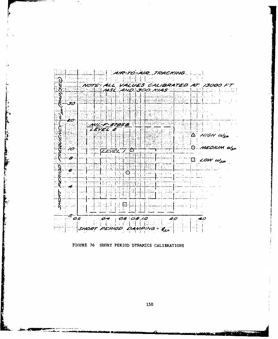
. ........... L LL i
.... L......4.--~-. -
7-." .. .: ý
X . V
It t
k I -.-
1 -7 7 __o L-
FIGURE 76 SHORT PERIOD DYNAMICS CALIBRATION4S
150
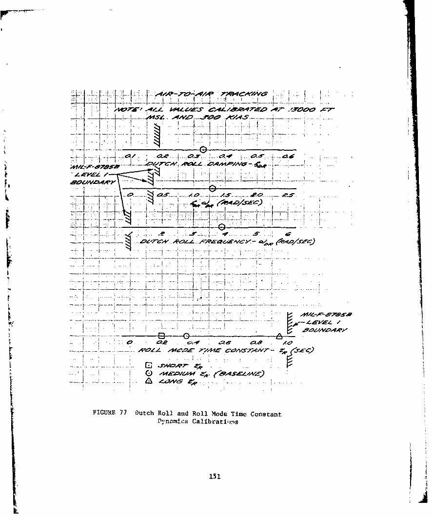
A.L
aOC*V~4A' - ~ ~
_ _-77
~"ri-
FIUE 7Dtc ol n Rl-Md ime±- Costn
Dynamics~ Calirat £n
I ... 151
acquisition or fine tracking. Recommend additional testing be conducteda- roll mode time constants between 0.4 and 0.9 seconds to further definethe upper boundary of satit3factory roll mode time constants for sidestickcontrolled aircraft.
OTHER DYNAMICS
Since the short roll mode time constant configurations with bothheavy and light force response configurations (DH and DL) were evaluatedby only one pilot who assigned equal ratings to the two configurations,there were insufficient data to determine a preferred force response.
For the high short period frequency (A), the heavy force response wasfavored for gross acquisition, and the light force was the main pilotcomment for the heave force response, whereas imprecise and oscillatorylongitudinal response was the prime comment for the light force responsecase. These force response preferences were not very strong in terms ofeither ratings or comments.
Due to the inconclusive results for the short roll mode time constantand high short period frequency configurations, recommend that furthertesting of these dynamics be conducted to provide an adequate sidestickdata base.
LONGITUDINAL AXIS
Given the heavy sidestick force response, the baseline medium shortperiod frequency configuration (C) was definitely the most preferred byall pilots for both the gross acquisition and fine tracking tasks. Withthe light force response, the pilots found the baseline longitudinalresponse less damped and more oscillatory.
Given the light sidestick force response, the low short periodfrequency configuration (B) was definitely the most preferred by allpilots for both the gross acquisition and fine tracking tasks. For thelow short period frequency with the heavy force response, the pilotscommented that the longitudinal stick forces were too high, but thelongitudinal response was still precise.
LATERAL AXIS
Given either the heavy or light sidestick force response, the baseline-oll mode time constant configuration (C) was definitely the most preferred
by all pilots for both gross acquisition and fine tracking tasks. Theshort r~oll mode time constant (D) was described as too sensitive with atendency to overcontrol. The long roll mode time constant (E) was describedas too sluggish and also led to overcontrol. These comments wereessentially the same for all three maneuvers.
152
For the two force responses used in this evaluation, pilot preferencefor force response was not constant throughout all dynamic sets, butchanged with variations in dynamics for both the gross acquisition andfine tracking tasks. In both cases of strong and conclusive pilot pre-ferences, the low short period frequency and the long roll mode timeconstant, the force response preferences were the same for both the grossacquisition and fine tracking tasks. Since the two force responses usedin this evaluation represent only a small portion of the feasible sidestickforce response and deflection gradient combinations, it is recommendedthat further testing with the same dynamic sets and other sidestickforce responses and deflection gradients should be conducted.
CONCLUSIONS AND RECOMMENDATIONS
All the specific test objectives of the NT-33A test project wereachieved. Overall analysis of the results showed pilot preference forsidestick force response characteristics was influenced by changes inaircraft dynamics during air-to-air gross acquisition and fine trackingtasks. For both the low short period frequency and the long roll mode
time constant, the force response preferences were the same for both thegross acquisition and fine tracking tasks. For the other dynamicstested, where the results were less conclusive, force response preferenceswere not the same for both tasks.
A large discrepancy existed in the case of the baseline dynamics (C),as illustrated by both the pilots' comments and ratings. Unexplainablesideslip oscillations and high pilot workload accompanied the poorratings and were absent for the good ratings.
1. Recommend that the sideslip oscillation problem be explored andresolved prior to any further testing.
2. Recommend that further testing with baseline dynamics be conductedto provide an adequate sidestick data base.
The low short period frequency/light force response combination wasthe highest rated configuration in this evaluation; however, the actualshort period frequency tested was below Levwl 1 of the current MIL-F-8785B(ASG).
3. Recommend additional testing, at es',en lower short period frequencies,be conducted to further define the'lower boundary of satisfactoryshort period frequency for sidestick controlled aircraft.
The long roll mode time constant was unsatisfactory and the leastpreferred configuration tested, regardless of the force response used.The long roll mode time constant actually tested met Level 1 of thecurrent MIL-F-8785B(ASG).
153L ...... 2.
•L
4. Recommend additional testing be conductel, at roll mode timeconstants between 0.4 and 0.9 seconds, to further define theupper boundary of roll mode time constants for sidestick con-trolled aircraft.
The test results were inconclusive for the short roll mode time constantand the high short period frequency configurations.
5. Recommend that further testing of these dynamics be conductedto provide an adequate sidestick data base.
The mwo force responses used in this evaluation represent only asmall port:lon of the feasible sidestick force response and deflectiongradient combinations.
6. Pecommend that further testing with the same dynamic sets andother sidest:ick force responses and deflection gradients beconducted.
154
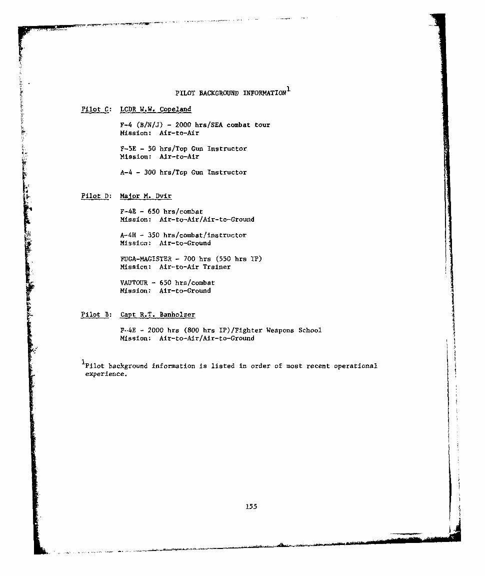
PILOT BACKGROUND INFORMATION1
Pilot C: LCDR W.W. Copeland
F-4 (B/N/J) - 2000 hrs/SEA combat tourMission: Air-to-Air
F-5E - 50 hrs/Top Gun InstructorMission: Air-to-Air
A-4 - 300 hrs/Top Gun Instructor
Pilot D: Major M. Dvir
F-4E - 650 hrs/combatMission: Air-to-Air/Air-to-Ground
A-4H - 350 hrs/combat/instructor
Mission: Air-to-Ground
FUGA-MAGISTER - 700 hrs (550 hrs IP)Missicn: Air-to-Air Trainer
VAUTOUR - 650 hrs/combatMission: Air-to-Ground
Pilot B: Capt R.T. Banholzer
F-04E - 2000 hrs (800 hrs IP)/Fighter Weapons SchoolMission: Air-to-Air/Air-to-Ground
iPilot background information is listed in order of most recent operationalexperience.
155
i.4
.... ~.
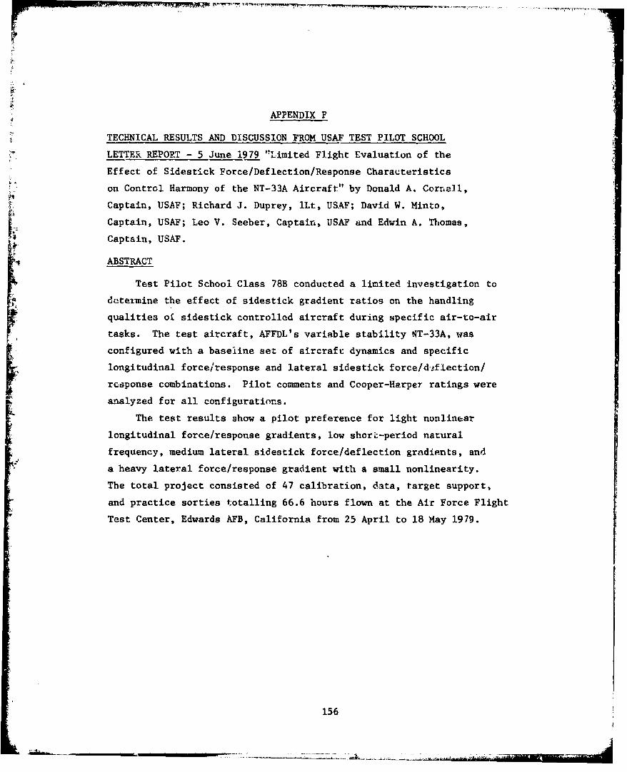
APPENDIX F
TECHNICAL RESULTS AND DISCUSSION FROM USAF TEST PILOT SCHOOL
LETTER REPORT - 5 June 1979 "Limited Flight Evaluation of the
Effect of Sidestick Force/Deflection/Response Characteristics
on Control Harmony of the NT-33A Aircraft" by Donald A. Cornell,
Captain, USAF; Richard J. Duprey, iLt, USAF; David W. Minto,
Captain, USAF; Leo V. Seeber, Captain, USAF and Edwin A. Thomas,
Captain, USAF.
ABSTRACT
Test Pilot School Class 78B conducted a limited investigation to
deteimine the effect of sidestick gradient ratios on the handling
qualities oi sidestick controlled aircraft during specific air-to-air
tasks. The test aircraft, AFFDL's variable stability NT-33A, was
configured with a baseline set of aircraft dynamics and specific
longitudinal force/response and lateral sidestick force/d!flection/
response combinations. Pilot comments and Cooper-Harper ratings were
analyzed for all configurations.
The test results show a pilot preference for light nonlinear
longitudinal force/response gradients, low short-period natural
frequency, medium lateral sidestick force/deflection gradients, and
a heavy lateral force/response gradient with a small nonlinearity.
The total project consisted of 47 calibration, data, target support,
and practice sorties totalling 66.6 hours flown at the Air Force Flight
Test Center, Edwards AFB, California from 25 April to 18 May 1979.
156
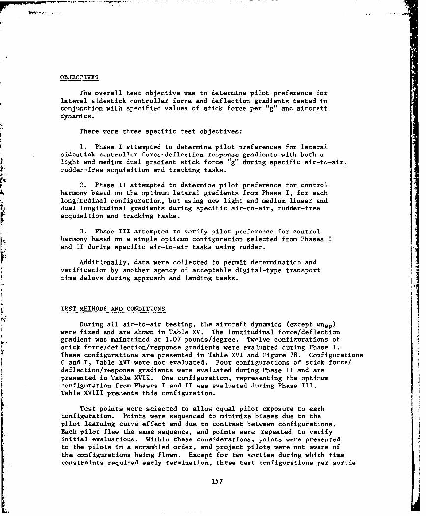
OBJECTIVES
The overall test objective was to determine pilot preference forlateral sIdestick controller force and deflection gradients tested inconjunction with specified values of stick force per "g" and aircraftdynamics.
There were three specific test objectives:
1. Phase I attempted to determine pilot preferences for lateralsidestick controller force-deflection-response gradients with both alight and medium dual gradient stick force "g" during specific air-to-air,rudder-free acquisition and tracking tasks.
2. Phase II attempted to determine pilot preference for controlharmony based on the optimum lateral gradients from Phase I, for eachlongitudinal configuration, but using new light and medium linear anddual longitudinal gradients during specific air-to-air, rudder-freeacquisition and tracking tasks.
3. Phase III attempted to verify pilot preference for controlharmony based on a single optimum configuration selected from Phases Iand II during specific air-to-air tasks using rudder.
Additlonally, data were collected to permit determination andverification by another agency of acceptable digital-type transporttime delays during approach and landing tasks.
TEST METHODS AND CONDITIONS
During all air-to-air testing, the aircraft dynamics (except wnsp)were fixed and are shown in Table XV. The longitudinal force/deflectiongradient was maintained at 1.07 pounds/degree. Twelve configurations ofstick f-rce/deflection/response gradients were evaluated during Phase I.These configurations are presented in Table XVI and Figure 78. ConfigurationsC and I, Table XVI were not evaluated. Four configurations of stick force/deflection/response gradients were evaluated during Phase II and arepresented in Table XVII. One configuration, representing the optimumconfiguration from Phases I and II was evaluated during Phase III.Table XVIII prezents this configuration.
Test points were selected to allow equal pilot exposure to eachconfiguration. Points were sequenced to minimize biases due to thepilot learning curve effect and due to contrast between configurations.Each pilot flew the same sequence, and points were repeated to verifyinitial evaluations. Within these considerations, points were presentedto the pilots in a scrambled order, and project pilots were not aware ofthe configurations being flown. Except for two sorties during which timeconstraints required early termination, three test configurations per sortie
157
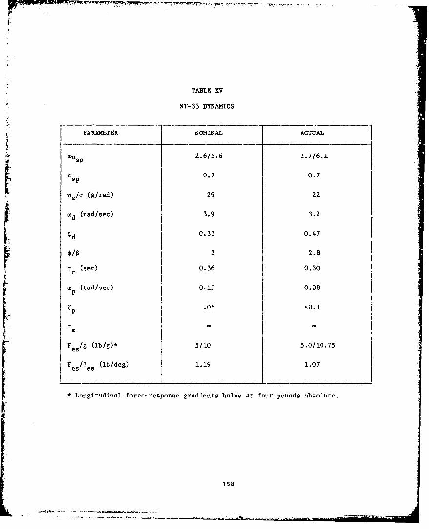
TABLE XV
NT-33 DYNAMICS
PARAMETER NOMINAL ACTUAL
wn 2.6/5.6 2.7/6.1
0.7 0.7
nzi, (g/rad) 29 22
wd (rad/sec) 3.9 3.2
[d0.33 0.47
*/B 2 2.8
Tr (sec) 0.36 0.30
w p (rad/gec) 0.15 0.08
.05
F /g (lb/g)* 5/10 5.0/10.75
F es/es (Ib/deg) 1.19 1.07
* Longitudinal force-response gradients halve at four pounds absolute.
158
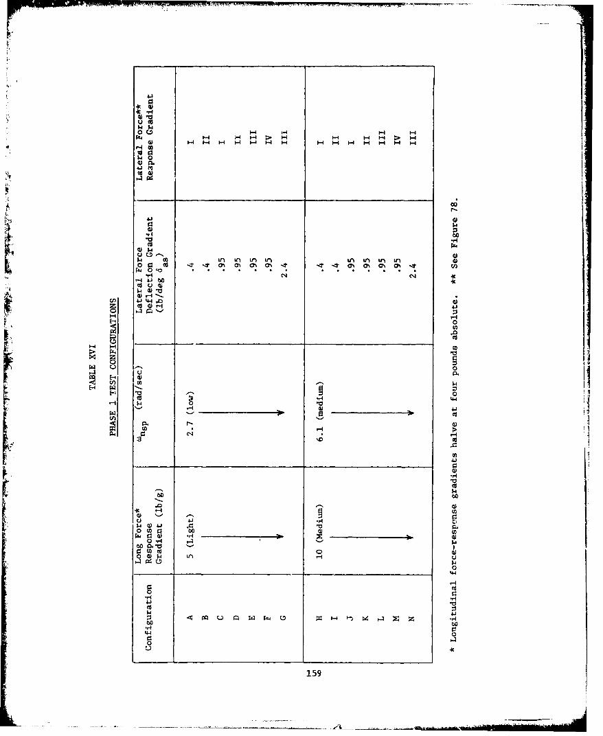
w .4
OC~H H H HH
14 0
41 M0
PrrI(C4
4J1 44 0i~ cI ir~u~ u U~ ~ ua~r4
0
ca 00
0 '-,
41
Aj C. ' ~' 4- J
00
415
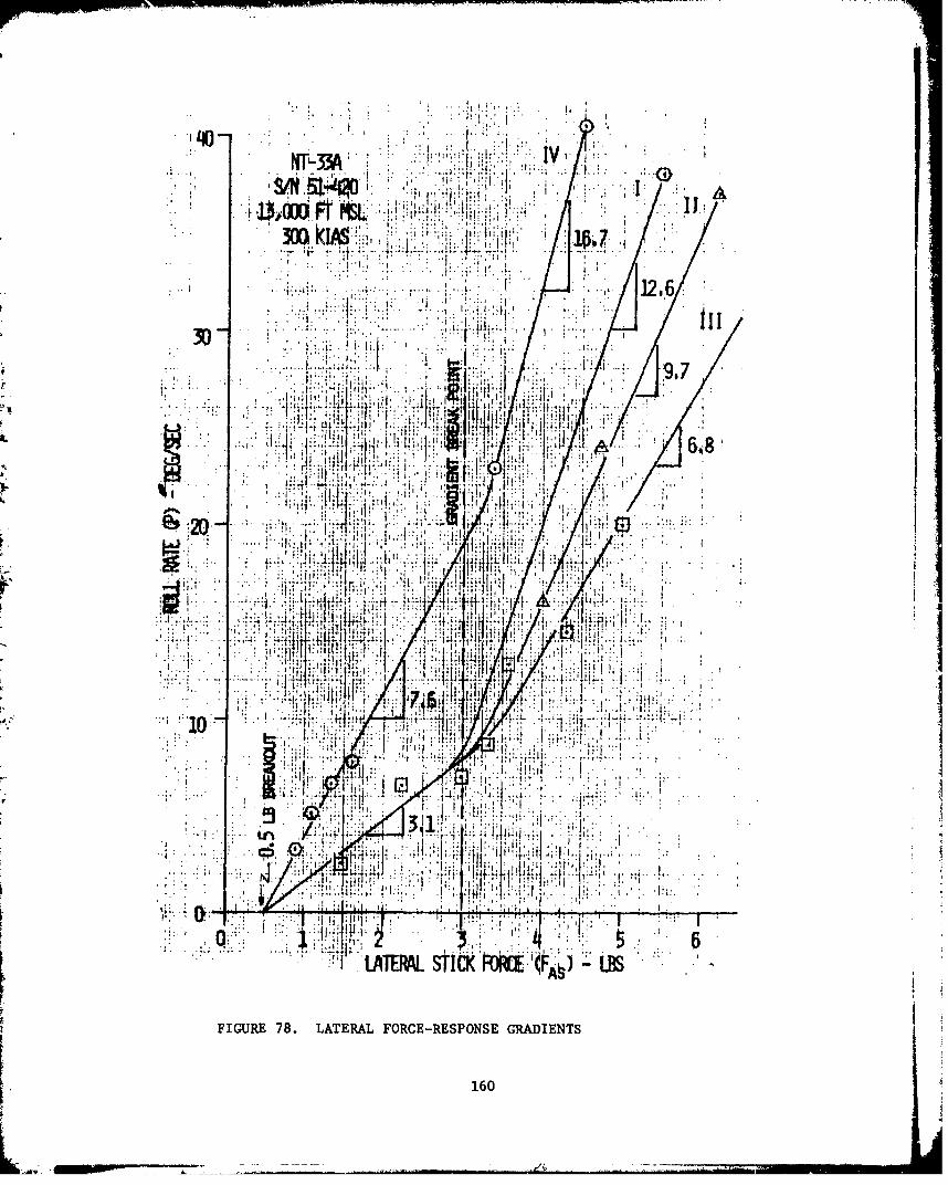
NT"3J13I
300 IA ~.1~' i. '., a
r!-j
:1I Tn I 12.6'
4i ...........I j
WEA ST*Pd I:)L~:-;r; ~A
LAERL. FOC-EPNEGA IETSJ
FIGURE ~ tI 78.!.~;L't
jr-160

CU
W 0 14.4 - H C
OJU 0.303
5.4G
5.4 q) rz
03 (UU 00314 __4.
0 o-44-- M
Cý k l-4 P 'C
E- o 4-4~00 ~044
0 .41
0 bo4 0
a) co
I-s ~~~$ W .. '.
Z1 41 t., coJ '
0 0
03) CU
CDC
0 0 CU 0J 0
1.4 to~H
".41
H I0Q
j j O
414
were evaluated for each task. Seven sorties per pilot were flown duringPhase I, two sorties per pilot during Phase II and one sortie was flownduring Phase III.
Each air-to-air task began with the NT-33A trimmed for level flightat 13,000 feet pressure altitude and 300 KIAS. The NT-33A was not re-trimmedduring the tasks. The tasks were performed without using the rudder (exceptfor Phase III) and using a fixed gunsight depression of 55 mils.
Three air-to-air tasks were flown to evaluate the gross acquisitionand fine tracking capabilities of each configuration. Maneuver #1 wasbegun with the NT-33A in trail at 1500 feet and co-airspeed. At thistime the T-38A initiated a 2g, 300 KIAS, level turn. The evaluation pilotwould wait till the T-38A crossed the canopy bow, call "hack", andaggressively maneuver to place and keep the pipper within 10 mils of theT-38A tailpipe junction. At this time, the evaluation pilot would call"tracking". When the evaluation pilot called "clear to reverse", theT-38A would perform an unloaded level reversal to a 2g, 300 KIAS levelturn in the opposite direction. The maneuver would then be repeated inthis direction until the evaluation pilot called "knock it off".
Maneuver #2 was begun with the NT-33A in trail at 1500 feet, co-airspeed,and both aircraft in 100 of bank. With the evaluation pilot tracking,the T-38A witnin 10 mils, the T-38A would iniLiate a wind-up turn from1 to 3.5g at a maximum onset rate of .2g per second. The evaluation pilotwould attempt to precisely, persistently, and aggressively keep thepipper centered on the T-38A tailpipe Junction. After reaching 3.5g, theT-38A would maintain 3.5g until the evaluation pilot considered themaneuver to be complete. Maneuver #2 was accomplished in each direction.
Maneuver #3 was begun with the NT-33A in trail at 1500 feet, co-airspeed,
with each aircraft in a 300 bank turn. With the evaluation pilot trackingthe T-38A within 10 mils, the T-38A would initiate a slow, smooth,modified "lazy 8" maneuver utilizing a constant 2g with bank angle changesof +900 and maximum pitch angles of +15 degrees. The evaluation pilotwould attempt to precisely, persistently, and aggressively keep the pippercentered on the tailpipe junction. Both aircraft accepted the resultingairspeed loss and did not attempt to maintain 300 KIAS throughout themaneuver. The maneuver was continued until the evaluation pilot consideredit complete.
At the conclusion of the evaluation of each configuration theevaluation pilot. completed the inflight comment card. The NT-33Amagnetic tape system, audio recorder, and gun camera were operatedduring each task.
Each evaluation pilot was thoroughly debriefed as soon as possibleafter landing in accordance with the mission debriefing guide.
162
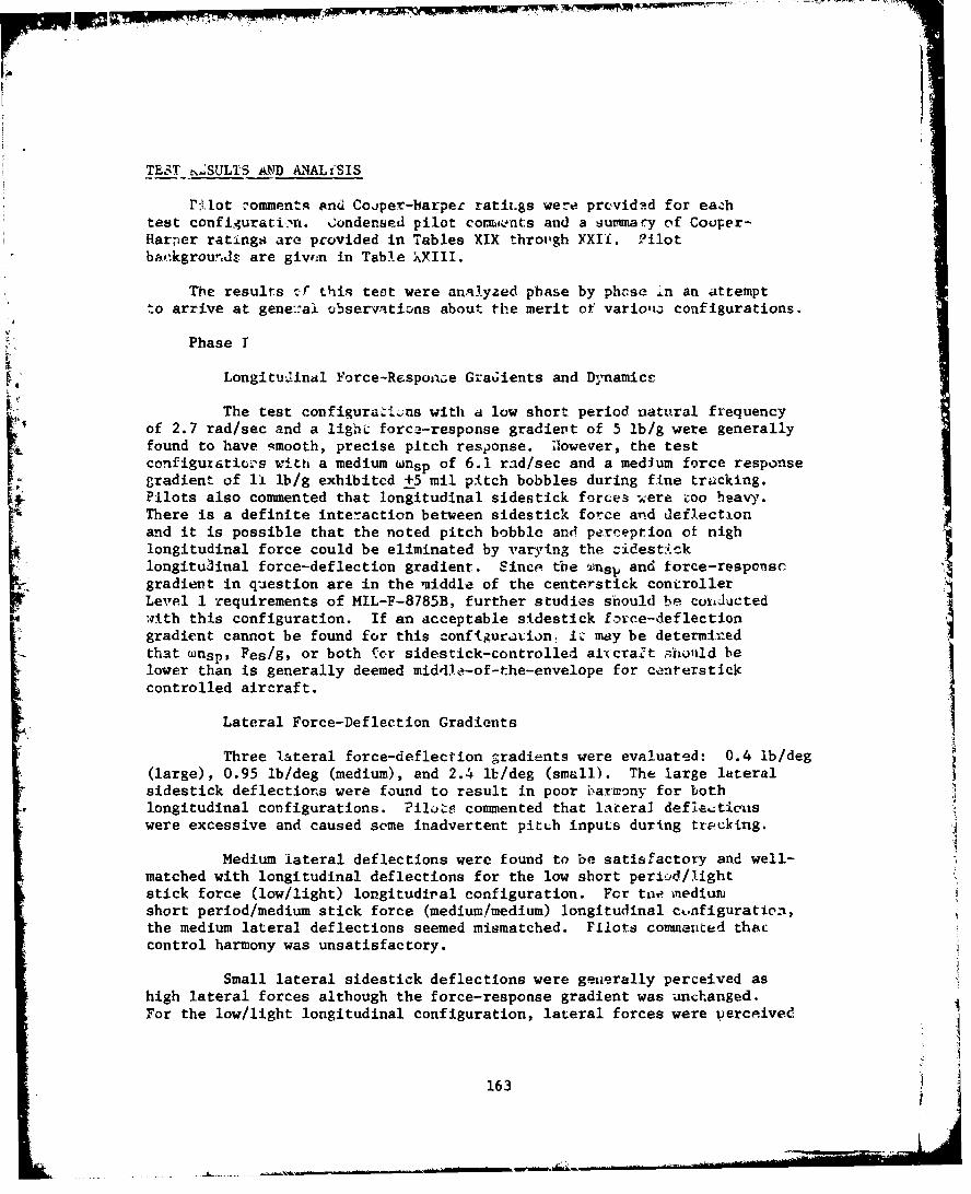
TEST NSULIS AND ANALrSIS
Pilot -omments and Cojper-harper ratit.gs were prcvidad for eachtest configurati:'n. Condensed pilot com, ents and a summary of Couper-Harper ratings are provided in Tables XIX throu'gh XXII.. ?ilotb.,4kgroundz are given in Table XXIII.
The results vT this test were analyzed phase by phnse in an attempt
to arrive at gene::ai ubservations about the merit of variolu configurations.
Phase I
Longitudinal Force-Respo-ne Graiients and Dnamics
The test configuraýL.:ns with a low short period natural frequencyof 2.7 rad/sec and a light force-response gradient of 5 lb/g were generallyfound to have smooth, precise pitch response. Uowever, the testconfiguratio's with a medium wnsp of 6.1 rad/sec and a medium force responsegradient of 11 lb/g exhibited +5 mil pitch bobbles during fine tracking.Pilots also commented that longitudinal sidestick forces were zoo heavy.There is a definite interaction between sidestick force and deflectionand it is possible that the noted pitch bobble and perception of nighlongitudinal force could be eliminated by varying the _idest~cklongituainal force-deflection gradient. Since the wnsp and force-responscgradient in question are in the middle of the centerstick controllerLevel 1 requirements of MIL-F-8785B, further studies should be coIJuetedwith this configuration. If an acceptable sidestick force-deflectiongradient cannot be found for this conftguravion: iz may be determiredthat wnsp, Fes/g, or both 1or sidestick-controlled aixuraft ýrahonld belower than is generally deemed middle-of-the-envelope for centerstickcontrolled aircraft.
Lateral Force-Deflection Gradientswd
Three lateral force-deflectlon gradients were evaluated: 0.4 rb/dega t(large), 0.95 lb/deg (medium), and 2.4 lb/deg (small). The large lateralsidestick deflections were found to result in poor iharmony for bothlongitudinal configurations. ?ilots commented that lateral deflecticiiswere excessive and caused some inadvertent pitch inputs during tracking.
Medium lateral deflections were found to be satisfactory and well-matched with longitudinal deflections for the low short perLid/lightstick force (low/light) longitudiral configuration. For tne inediumnshort period/medium stick force (medium/medium) longitudinal ctnfiguration,the medium lateral deflections seemed mismatched. Pilots commerited thaccontrol harmony was unsatisfactory.
Small lateral sidestick deflections were generally perceived ashigh lateral forces although the force-response gradient was unchanged.For the low/light longitudinal configuration, lateral forces were perceived
1634
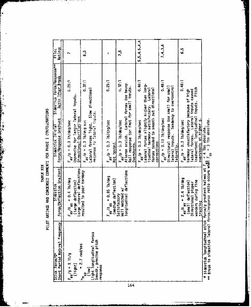
00 =f a
0.
IX LeI-
goo
LI
cc Ln o" c to.t
u 4-
L. 5-4 o(b4 , 0 c-
4If c ,W44-- 0* #A
41 4*$at 4-1 1.u- J-5 uL 4
w. a ) -4L. knC n
- 0to -r- I0. u-* 0 z u u V 1 u - 0--5 - u 10C
4Jj L. - _ __ft._ a_ _ _ _(
a 4u 0 604
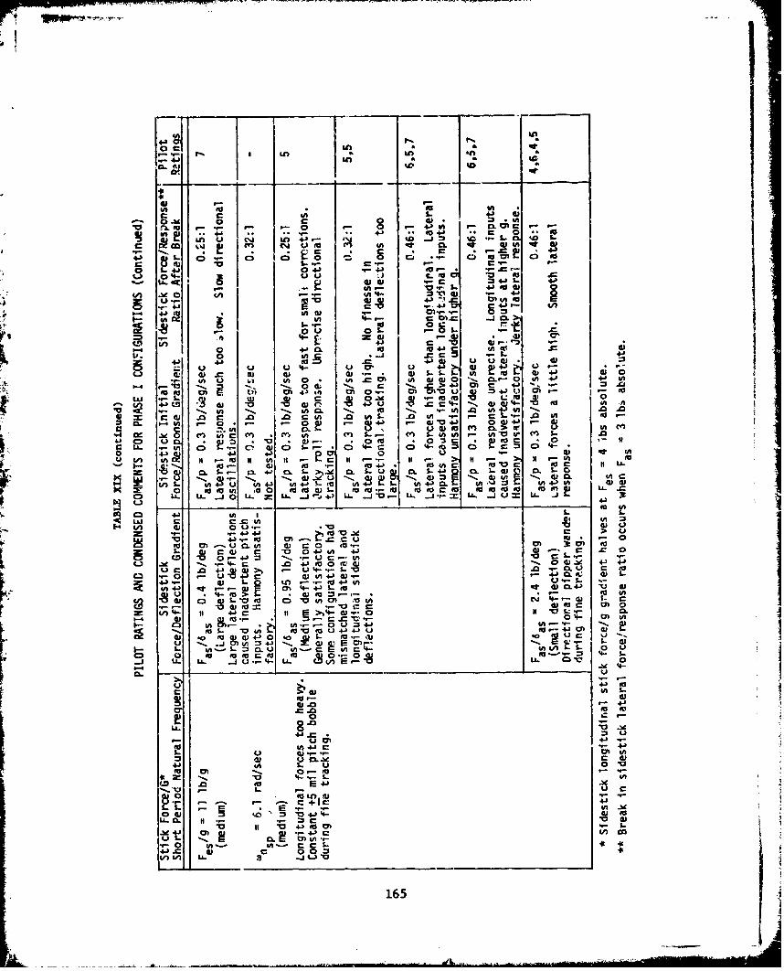
V M8 06 C
oct Vt C
U) Eu Ju
LO,~.- C.,=JL. 5
"c "W & 4-' 01Q,
• 4-3 a "e- 4- t
. - 4J~ u-.i -0 - 4J C 4J' 0. %i
4b 04- m 0 =0) ~ ~21 0) r. 0 . 0W 40.'- 4J 0 e" I .6 E.-
0 CL-. +.- c
-j =,.= 9 .L 4J
fd,4J U L 4
u S.4. 04-' -- 4i Zi 4i
0) -C CU .) 0 S- I E..) L i" U 0 " 0 m C- - 0 #A 4- 44 V)
4L- 4 IM-, C 4J .) E
E t..4t Ch.•- UM 4-. tn 4j U IM :•-n .8 c 0 0
4jCD- n 4 U O1. 4 A.
a *-- .- ,, 4-,- .- 0 . -V) w .m
m " AU 0-, 4J 4,- ,,,,--
Ur he 0 4n ) * 0 (n M &M S o. wMd . CL 0 . IV
C: OA Cý w 0) I D 0 ;4
0 4J 4,--. - 0 -t CAJ.£'-. ,- 14-'',U 0 t C 1 1 t > t #
.~0 ~) * ( .. U) (• . ..- t ~ -.
'L"- 4 01 0 C. .Or
U l) n K .-- U 0 ) it ,--.,-C I ~ I ,.-.,- E.-u
2C 06. 4j m. S-> 0. -U S~-4 06 - Q -
M. LM
"=I LLý ea3: .le-"o to.e c f" r"f a
#A io o to M- ,- I ,-
C) 1 -U- C o L.) LA4-- 43 - 0I.)- 1
C3- 4--.0.-EuI 0).-U ) " ) - E 0c-- 0 #Am 0 :"
S. --- a. ca i•. ut.-. O4-) E - 03., t-..
On CQ 0 U.' w..- C v)- L,
L L , .. .-' 4 .-.C - I.0 4 ..0O'V a,.' • O0). 4- 4-
-1 0 41 0 la 0)0
T-- M -U -4) 0 0 do-- m toC ) .. "c 0 0 4) 4 05, E 4u MC0.- bee- "-1"1 U j 0 0 u044- 4
u 0 4 84a3 >,- U 4 u- .- S.- .0 E U c 4CA ý u 1) 4 N ff. ; - 0 ) S.
, 4-. I %- n - -- 0 4 #A - 0.r' @A4-4*0,4 4J cc0.- *C 0)C. "M' O4J T) d)
w E ; *- -0 'oto AVU.4' Eur 4+-' 0) w0)t =0 g00,- 0. ., E-- w to c J t 0
o 0 Eu 4 ,JE • 4- d- o. oE ; m-
t= ".- P"5
6 8 9 0 U 4
M)0 4)0 - 0 - -.
4- . - J U 4 LA Un 0.. Q- 0
L-4 .b- 4 *
LL.0 K0 go- to 0
16
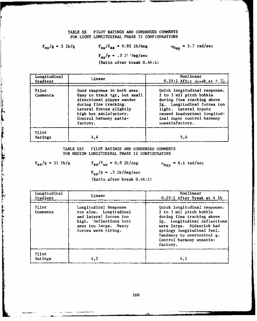
TABLE XX PILOT RATINGS AND CONDENSED COMMENTSFOR LIGHT LONGITUDINAL PHASE II CONFIGURATIONS
Fes/- 5 lb/g Fas/ 6 as - 0.95 Ib/deg -nsp 2.7 rad/sec
Fas/p - .3 11/ deg/sec
(Ratio after break 0.46:1)
Longitudinal Linear NonlinearGradient .... _0.25:1 After 4itak at 6 lb
Pilot Good response in both axes. Quick longitudinal response.Comments Easy to track tgt, but small 2 to 3 mil pitch bobble
directional pipper wander during fine tracking aboveduring fine tracking. 2g. Longitudinal forces tooLateral forces slightly light. Lateral inputshigh but satisfactory. caused inadvertent longitud-Control harmony satis- inal input control harmonyfactory. unsatisfactory.
-_____
PilotRatings 4,4 5,4
TABLE XXI PILOT RATINGS AND CONDENSED COMMENTSFOR MEDIUM LONGITUDINAL PHASE Ii CONFIGURATINS
Fes/9 - 11 lb/g Fas/6as = 0.8 ib/deg Wnsp = 6.1 rad/sec
Fas/p = .3 lb/deg/sec
(Ratio after break 0.46:1)
Longitudinal Linear NonlinearGradient 0.25:1 After Break at 4 lb
Pilot Longitudinal Response Quick longitudinal response.
Comments too slow. Longitudinal 2 to 3 mil pitch bobbleand lateral forces too during fine tracking abovehigh. Deflections both 2g. Longitudinal deflectionsaxes too large. Heavy were large. Sidestick hadforces were tiring, springy longitudinal feel.
Tendency to overcontrol g.
Control harmony unsatis-factory.
PilotRatings 4,5 4,5
166
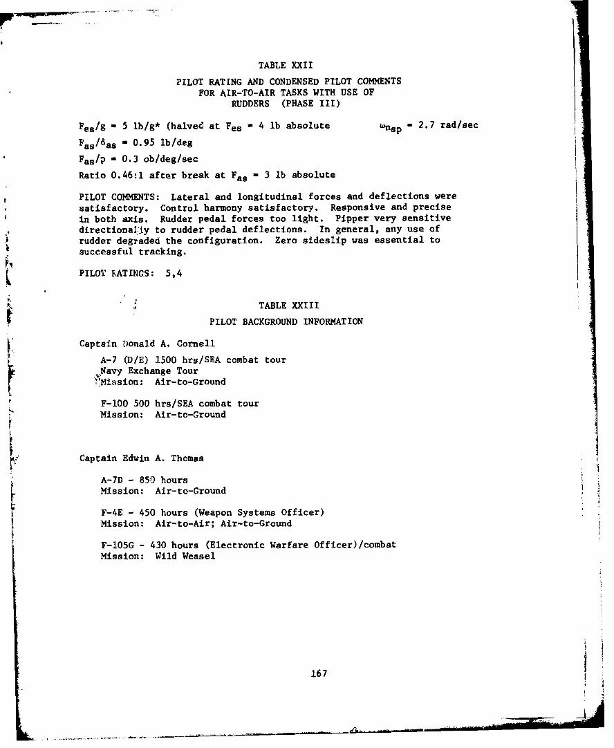
TABLE XXII
PILOT RATING AND CONDENSED PILOT COMMENTSFOR AIR-TO-AIR TASKS WITH USE OF
RUDDERS (PHASE III)
Fes/- 5 lb/g* (halved at Fes - 4 lb absolute nsp- 2.7 rad/sec
Fas/ 6as - 0.95 Ib/deg
Fas/p - 0.3 ob/deg/sec
Ratio 0.46:1 after break at Fas - 3 lb absolute
PILOT COMMENTS: Lateral and longitudinal forces and deflections weresatisfactory. Control harmony satisfactory. Responsive and precisein both axis. Rudder pedal forces too light. Pipper very sensitivedirectional-1y to rudder pedal deflections. In general, any use ofrudder degraded the configuration. Zero sideslip was essential tosuccessful tracking.
PILOT RATINGS: 5,4
TABLE XXIII
PILOT BACKGROUND INFORMATION
Captain Donald A. Cornell
A-7 (DIE) 1500 hrs/SEA combat tour
,-Pavy Exchange Tour.'Mi!sion: Air-to-Ground
F-1O0 500 hrs/SEA combat tourMission: Air-to-Ground
Captain Edwin A. Thomas
A-7D - 850 hoursMission: Air-to-Ground
F-4E - 450 hours (Weapon Systems Officer)Mission: Air-to-Air; Air-to-Ground
F-105G - 430 hours (Electronic Warfare Officer)/combatMission: Wild Weasel
167
- -------------
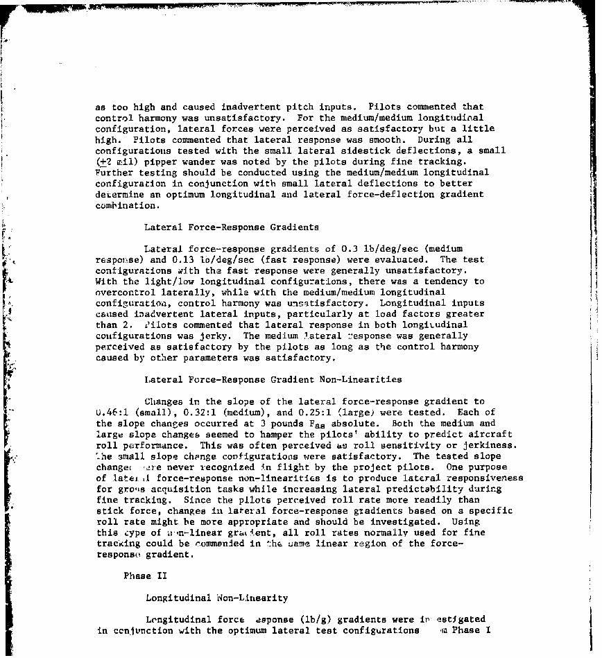
as too high and caused inadvertent pitch inputs. Pilots commented thatcontrol harmony was unsatisfactory. For the medium/medium longitudinalconfiguration, lateral forces were perceived as satisfactory but a littlehigh. Pilots commented that lateral response was smooth. During allconfigurations tested with the small lateral sidestick deflections, a small(+2 mil) pipper wander was noted by the pilots during fine tracking.Further testing should be conducted using the medium/medium longitudinalconfiguration in conjunction with small lateral deflections to betterdetermine an optimum longitudinal and lateral force-deflection gradientcombination.
Lateral Force-Response Gradients
IrLateral force-response gradients of 0.3 ib/deg/sec (medium
respol•se) and 0.13 1o/deg/sec (fast response) were evaluated. The testconfigurations with the fast response were generally unsatisfactory.With the light/low longitudinal configurations, there was a tendency toovercontrol laterally, while with the medium/medium longitudinalconfiguration, control harmony was unsatisfactory. Longitudinal inputscaused inadvertent lateral inputs, particularly at load factors greaterthan 2. ,'ilots commented that lateral response in both longitudinalconfigurations was jerky. The medium lateral ::esponse was generallyperceived as satisfactory by the pilots as long as the control harmonycaused by other parameters was satisfactory.
Lateral Force-Response Gradient Non-Linearities
Changes in the slope of the lateral force-response gradient toU.46:1 (small), 0.32:1 (medium), and 0.25:1 (large) were tested. Each ofthe slope changes occurred at 3 pounds Fas absolute. Both the medium andlarge slope changes seemed to hamper the pilots' ability to predict aircraftroll performance. This was often perceived as roll sensitivity or jerkiness.'-he small slope change copfigurations were satisfactory. The tested slopechange •'re never recognized !.n flight by the project pilots. One purposeof latei ,I force-response non-linearities is to produce lateral responsivenessfor gros acquisition tasks while increasing lateral predictability duringfine tracking. Since the pilots perceived roll rate more readily thanstick force, changes in lateral force-response gradients based on a specificroll rate might be more appropriate and should be investigated. Usingthis cype of awn-linear gratient, all roll rates normallv used for finetracking could be commanied in the uame linear region of the force-responso gradient.
Phase II
Longitudinal Won-Linearity
Longitudinal force asponse (lb/g) gradients were ir estlgatedin ccnlunction with the optimum lateral test configurations m Phase I
I I

(Bee Table XVII). Changes in the slope of longitudinal force-responsegradients of 1:1 (linear), 0.5:1 (medium), and 0.25:1 (large) were testedfor both light/low and medium/medium longitudinal configurations. Eachslope change occurred at 4 lbs, Fes absolute.
The linear longitudinal force-response gradient was clearlyunacceptable for medium/medium longitudinal configurations due toexcessively high longitudinal stick forces. For the light/low longitudinalconfigurations, the linear gradient was satisfactory.
The medium longitudinal force-response gradient change was thelongitudinal test configuration during all of Phase I. As stated previously,this was satisfactory for the light/low test configuration while pitchbobbles occurred with the medium/medium configuration.
The large lonigitudinal force-response gradient change was foundto impact on the pilots' ability to predict aircraft longitudinal response.With the light/low longitudinal configuration, pitch bobbles occurredduring fine tracking with the large gradient change. With the medi~um/medium longitudinal configuration, the pilots' previously mentioned pitchbobble problem increased. Pilots commented in both cases that there wasan apparent stick-force lightening and a tendency for the aircraft to digin at higher g's.
As noted for lateral gradient changes, longitudinal force-responsegradient changes based on aircraft response rather than stick force shouldbe investigated.
Phase III
During Phase III, the optimum configuration found during Phases Iand II (see Table XVIII) was tested while allowing the pilot to useIrudder inputs to attempt to enhance his tracking. It was found withthe directional configuration of the NT-33A that the use of rudder duringIfine tracking detracted from pilot performance. This conclusion is limitedonly to the configuration tested. Further testing should be conductedto investigate directional force-response changes on an optimum-longitudinal/lateral configuration.
CONCLUSIONS AND RECOMMENDATIONS
The lateral configuration3 found to have the best handling qualitiesriuring Phase I had the following parameters:
F / F /p before break Fas/p ratio afterae as as a
(__lb ____) (lb/deg sec) break
0.95 0.3 0.46:1
2.4 0.1 0.46:1
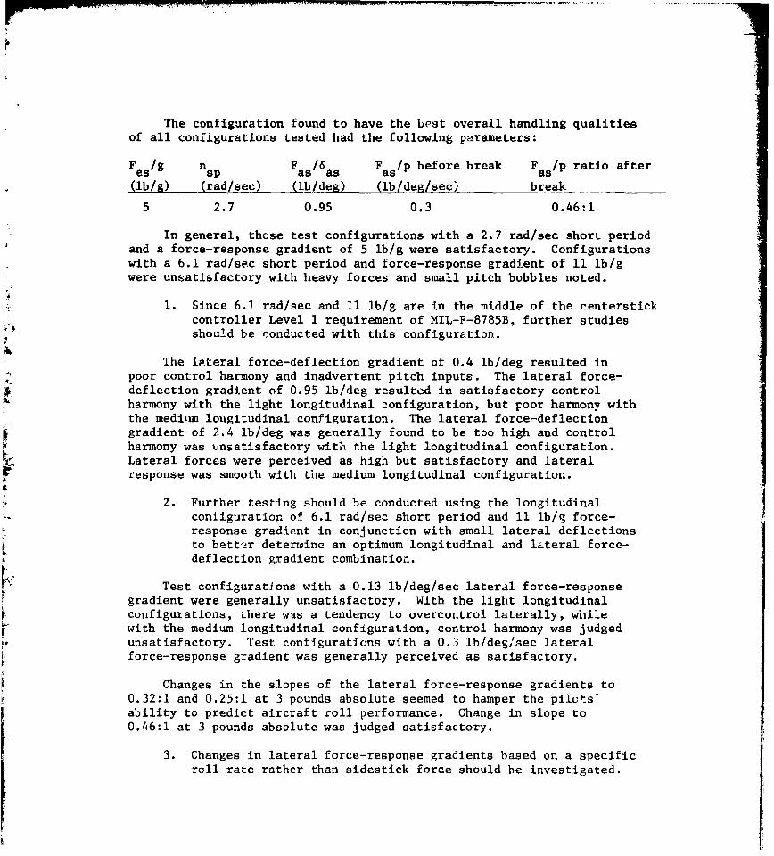
The configuration found to have the best overall handling qualitiesof all configurations tested had the following parameters:
F es/g nsp F as/6as F as/p before break F as/p ratio after
(lb/g) (rad/sec) (!b/deg) (lb/deg/sec) break
5 2.7 0.95 0.3 0.46:1
In general, those test configurations with a 2.7 rad/sec short periodand a force-response gradient of 5 lb/g were satisfactory. Configurationswith a 6.1 rad/sec short period and force-response gradient of 11 lb/gwere unsatisfactory with heavy forces and small pitch bobbles noted.
1. Since 6.1 rad/sec and 11 lb/g are in the middle of the centerstickcontroller Level 1 requirement of MIL-F-8785B, further studiesshould be conducted with this configuration.
The lateral force-deflection gradient of 0.4 ib/deg resulted inpoor control harmony and inadvertent pitch inputs. The lateral force-deflection gradient of 0.95 lb/deg resulted in satisfactory controlharmony with the light longitudinal configuration, but poor harmony withthe medilun lougitudinal configuration. The lateral force-deflectiongradient of 2.4 ib/deg was generally found to be too high and controlharmony was unsatisfactory with the light longitudinal configuration.Lateral forces were perceived as high but satisfactory and lateralresponse was smooth with the medium longitudinal configuration.
2. Further testing should be conducted using the longitudinalconfiguration of 6.1 rad/sec short period and 11 lb/g force-response gradient in conjunction with small lateral deflectionsto better determine an optimum longitudinal and lateral force-deflection gradient combination.
Test configurations with a 0.13 lb/deg/sec lateral force-responsegradient were generally unsatisfactory. With the light longitudinalconfigurations, there was a tendency to overcontrol laterally, whilewith the medium longitudinal configuration, control harmony was judgedunsatisfactory. Test configurations with a 0.3 lb/deg/sec lateralforce-response gradient was generally perceived as satisfactory.
Changes in the slopes of the lateral force-response gradients to0.32:1 and 0.25:1 at 3 pounds absolute seemed to hamper the pilets'ability to predict aircraft roll performance. Change in slope to0.46:1 at 3 pounds absolute was judged satisfactory.
3. Changes in lateral force-response gradients based on a specificroll rate rather than sidestick force should be investigated.
The linear longitudinal force-response gradient of 11 lb/g wasunacceptable due to high longitudinal stick forces. The linear 5 lb/ggradient was judged acceptable.
The longitudinal force-response gradient change of 0.25:1 at 4pounds absolute was judged unsatisfactory in conjunction with both the5 and 11 lb/g longitudinal force-response gradient, due to pitchbobbles and an apparent stick force lightening at higher g.
4. Longitudinal force-response gradient changes based on aircraftresponse rather than stick force should be investigated.
With the directional characteristics of the NT-33A as configured,the use of rudder during fine tracking detracted from pilot performance.
5. Further testing should be conducted to investigate directionalforce-response changes on an optimum longitudinal/lateralconfiguration.
I.I
REFERENCES
1. Hall, G. Warren and Smith, Rogers E., "Flight Investigation ofFighter Sidestick Force-Deflection Characteristic", AFFDL-TR-75-39, May 1975.
2. Cima, William M., Lieutenant, USAF, et al, "Limited FlightEvaluation of Sidestick Controller Force-DeflectionCharacteristics on Aircraft Handling Qualities", USAF TestPilot School Letter Report, I July 1977, also AFFDL-TR-77-34, Nov. 74.
3. Saxon, Vernon P., Capt, USAF, et al, "Limited Flight Evaluation ofthe Effect of Sidestick Force-Deflection Characteristics onAircraft Handling Qualities", USAF Test Pilot School LetterReport, 9 December 1977.
4. Lewis, Gregory V., Capt, USAF, et al, "Limited Flight Evaluationof the Effect of First Order Prefilters on the Handling Qualitiesof Sidestick Controlled Aircraft", USAF Test Pilot School Letter
r Report, 5 July 1978.
5. Copeland, W.W., LCDR, USN, et al, "Limited Flight Evaluation ofthe Fffect of Modal Dynamic Variations on the Handling Qualitiesof Sidestick Controlled Aircraft", USAF Test Pilot School LetterReport, 6 December 1978.
6. Cornell, Donald A, Capt, USAF, et al, "Limited Flight Evaluation ofthe Effect of Sidestick Force-Deflection-Response Characteristics onControl Harmony of the NT-33A Aircraft", USAF Test Pilot School LetterReport, 5 June 1979.
7. Smith, Stephen B. and Miller, Charles M., Capt, USAF, "AnEvaluation of Sidestick Force-Deflection Characteristics on
Aircraft Handling Qualities", AFFDL-TR-78-171, pp. 395-413,December 1978.
8. Kuehnel, Helmut A., and Sommer, Robert W., "Flight Investigationof the Acceptability of a Small Side-Located Co~ltroller used withan Irreversible Hydraulic Control System", NACA-TN-4297, 1958.
9. "Estimated Flying Qualities of the X-15 Research Airplane, NAAModel No. NA-240", Contract AF33(600)-31693, System 605A,Volume I, Static Stability and Control NA-59-1379, NorthAmerican Aviation, Inc., 18 August 1959.
10. Graves, Harry C., et al, "Study and Development of an ElectricSidestlick Controller for Aerospace Vehicles", ASD-TR-61-603May 1962.
11. Jenney, Gavin D., "JB-47E Fly-By-Wire Flight Test Program (Phase I)",AFFDL-TR-69-40, September 1969.
12. Theurer, Byron W., Capt, USAF and Staten, Kenneth E., Capt,USAF, "F-104D Sidestick Control System", The Society ofExperimental Test Pilots 1970 Report to the AerospaceProfession, pp. 199-220.
13. Hall, G.W., Huber, R.W. and Close, W., "Development of an AirplaneElectrohydraulic Variable Feel Sidestick Flight Controller",Calspan Report No. AK-5280-F-3, Sept 1974.
14. Garland, Michael P., "F-16A Movable Stick Evaluation", Air ForceFlight Test Center, TER FQ-01, 19 June 1978.
15. Larson, Howard B., et al, "Military Transport (C-141) Fly-By-WireProgram, Vol I: Control Law Development, System Design andPiloted Simulation Evaluation", AFFDL-TR-74-52, April 1974.
16. Larson, Howard B., et al, "Military Transport (C-141) Fly-By-WireProgram, Vol II: Hardware Installation and Flight", AFFDL-TR-74-52, Vol II, June 1974.
17. Knowles, W.B., "Primary Controller Designs for Jet Transports",AFFDL-TR-66-203, March 1966.
18. Rhoads, Donald W., "In-Flight Evaluation of Four Cockpit ControllerConfigurations in a Variable Stability Airplane", AFFDL-TR-70-95,September 1970.
19. Cazenave, A. and Irvoas, J., "Resultats Relatifs a L'Experimentationsur Simulateur et En Vol d'un Systeme de Commandes de VolElectriques Generalisables", AGARD Conference Proceedings AGARD-CP-260, Sept 1978.
20. Berven, Lester F., "BD-5 Flight Test Program Report", The Societyof Experimental lest Pilots 1973 Report to the Aerospace Profession,pp. 201-210.
21. Farrari, Charles J., Major, USAF, et al, "BD-5J Limited Performanceand Flying Qualities Evaluation", USAF Test Pilot School LetterReport, March 1975.
22. Twisdale, T.R. and Franklin, D.L., "Tracking Test Techniques forHandling Qualities Evaluation", AFFTC-TR-75-1, May 1975.
23. Duprey, Richard, iLt, USAF, "SidestIck Controller Design Criteria",Unpublished Memo for the Record, 22 May 1978.
24. Anon, "Military Specification, Flying Qualities of Filoted Airplanes",MIL-F-8785B (ASG). 7 August 1969.
173
25. Chalk, Charles R., et al, "Revisions to MIL-F-8785B (ASG) Proposedby Cornell Aeronautical Laboratory under contract F33615-71-C-1254",AFFDL-TR-72-41, April 1973.
26. Smith, Ralph H. and Geddes, Norman D., "New Criteria for AdvancedAircraft Design", AFFDL-TR-78-171, pp. 545-573, December 1978.
27. Chalk, C.R., et al, "Background Information and User Guide forMIL-F-8785B (ASG), 'Military Sp~ecification - Flying Qualities ofPiloted Airplanes"', AFFDL-TR-69-72, August 1969.
28. Mooij, H.A., de Boer, W.P. and van Gool, M.F.C., "A SimulatorInvestigation of Handling Quality Criteria for CCV TransportAircraft", presented at the AGARD Symposium on Stability andControl, Ottawa, September 1978.
29. Smith, R.H., "A Theory for Handling Qualities with Applicationsto MIL-F-8785B", AFFDL-TR-75-119, October 1976.
174
ADDITIONAL BIBLIOGRAPHY
Assadourian, Authur, "Ground Simulator Studies of a Small Side LocatedController in a Power Control System", NACA RM L58B14, April 23, 1958.
Bressenden, Ray F., "Some Ground Measurements of Forces Applied byPilots to a Side-Located Aircraft Controller", NACA TN-4171, November 1957.
Eckhart, Franklin F., "Investigation of a Side-Arm Controller During In-Flight Simulation of an Unaugmented Space Shuttle Orbiter in the UnpoweredLanding Approach", Calspan Report CAL No. AK-5101-F-2, November 1972.
"Experience with the X-15 Adaptive Flight Control System", NASA TN-D-6208,March 1971.
Hall, H.J., Jr., et al, "Design and Evaluation of Primary Hand Cont:ollersfor Fighter Aircraft", AFFDL-TR-71-16, July 1971.
Layton, Donald M., "A Simulator Evaluation of Pilot Performance anJAcceptance of an Aircraft Rigid Cockpit Control System", US NavalPostgraduate School report NPS-57LN70071A, 15 July 1970.
Mattes, R.E., and Asicla, C.F., "High Acceleration Cockpit ControllerLocations", AFFDL-TR-75-58, Vol I, May 1975.
Sjoberg, S.A., et al, "Flight Investigations of a Small Side-LocatedControl Stick used with Electronic Control Systems in a FighterAirplane", NACA RM-L56228a.
Winner, R.N., "Development of Three Improved Primary Flight ControllerDesigns", AFFDL-TR-68-72, July 1968.
Wittier, Frank E., "Apollo Experience Report - Crew Station Integration,Volume III - Spacecraft Hand Controller Development", NASA TN-D-7884,March 1975.
17
S~175