Embed Size (px)
Citation preview
Flyin' Miata970.464.5600
Rev 1.0
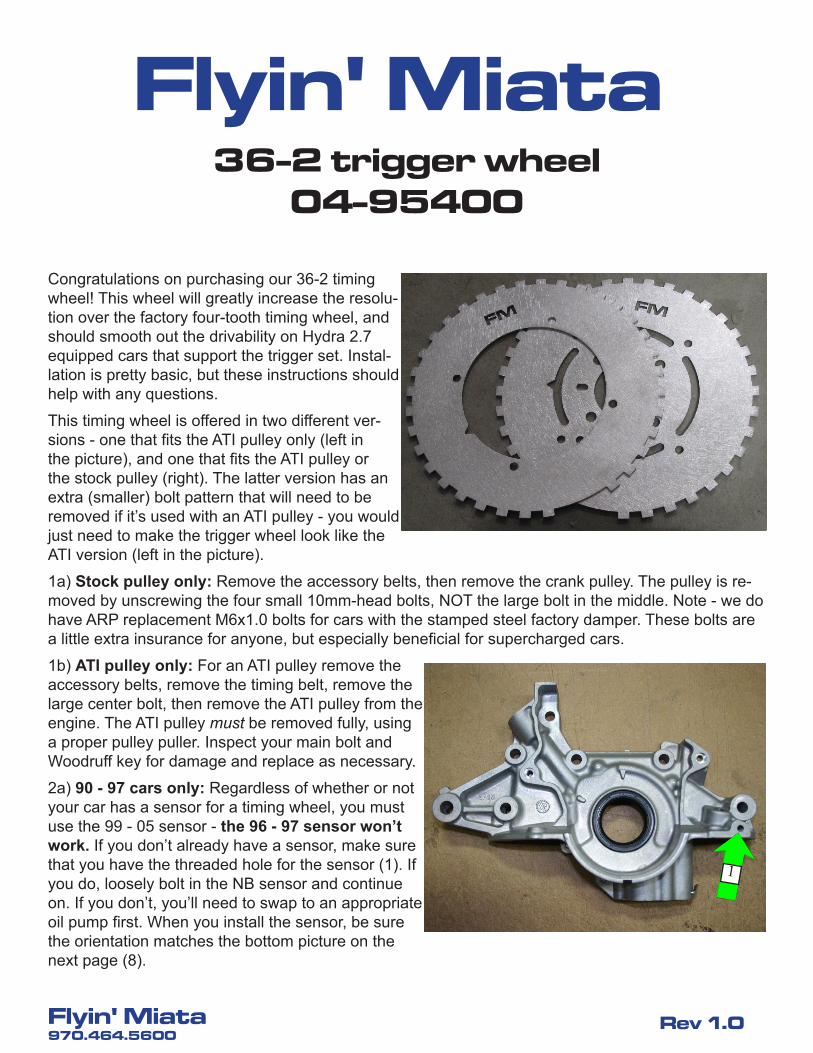
Congratulations on purchasing our 36-2 timing wheel! This wheel will greatly increase the resolu-tion over the factory four-tooth timing wheel, and should smooth out the drivability on Hydra 2.7 equipped cars that support the trigger set. Instal-lation is pretty basic, but these instructions should help with any questions.
This timing wheel is offered in two different ver-sions - one that fits the ATI pulley only (left in the picture), and one that fits the ATI pulley or the stock pulley (right). The latter version has an extra (smaller) bolt pattern that will need to be removed if it’s used with an ATI pulley - you would just need to make the trigger wheel look like the ATI version (left in the picture).
1a) Stock pulley only: Remove the accessory belts, then remove the crank pulley. The pulley is re-moved by unscrewing the four small 10mm-head bolts, NOT the large bolt in the middle. Note - we do have ARP replacement M6x1.0 bolts for cars with the stamped steel factory damper. These bolts are a little extra insurance for anyone, but especially beneficial for supercharged cars.
1b) ATI pulley only: For an ATI pulley remove the accessory belts, remove the timing belt, remove the large center bolt, then remove the ATI pulley from the engine. The ATI pulley must be removed fully, using a proper pulley puller. Inspect your main bolt and Woodruff key for damage and replace as necessary.
2a) 90 - 97 cars only: Regardless of whether or not your car has a sensor for a timing wheel, you must use the 99 - 05 sensor - the 96 - 97 sensor won’t work. If you don’t already have a sensor, make sure that you have the threaded hole for the sensor (1). If you do, loosely bolt in the NB sensor and continue on. If you don’t, you’ll need to swap to an appropriate oil pump first. When you install the sensor, be sure the orientation matches the bottom picture on the next page (8).
1
36-2 trigger wheel04-95400
Flyin' Miata
Flyin' Miata970.464.5600
Rev 1.0
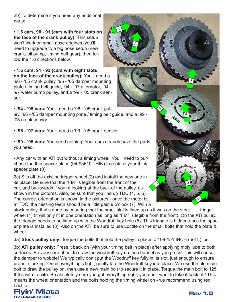
2b) To determine if you need any additional parts:
• 1.6 cars, 90 - 91 (cars with four slots on the face of the crank pulley): This setup won’t work on small nose engines, you’ll need to upgrade to a big nose setup (new crank, oil pump, timing belt gear), then fol-low the 1.6 directions below.
• 1.6 cars, 91 - 93 (cars with eight slots on the face of the crank pulley): You’ll need a ‘96 - ‘05 crank pulley, ‘96 - ‘05 damper mounting plate / timing belt guide, ‘94 - ‘97 alternator, ‘94 - ‘97 water pump pulley, and a ‘99 - ‘05 crank sen-sor.
• ‘94 - ‘95 cars: You’ll need a ‘96 - ‘05 crank pul-ley, ‘96 - ‘05 damper mounting plate / timing belt guide, and a ‘99 - ‘05 crank sensor.
• ‘96 - ‘97 cars: You’ll need a ‘99 - ‘05 crank sensor.
• ‘99 - ‘05 cars: You need nothing! Your cars already have the parts you need.
• Any car with an ATI but without a timing wheel: You’ll need to pur-chase the thin spacer place (04-95510 THIN) to replace your thick spacer plate (3)
2c) Slip off the existing trigger wheel (2) and install the new one in its place. Be sure that the “FM” is legible from the front of the car, and backwards if you’re looking at the back of the pulley, as shown in the pictures. Also, be sure that you line up TDC (4, 5, 6). The correct orientation is shown in the pictures - once the motor is at TDC, the missing teeth should be a little past 9 o’clock (7). With a stock pulley, that’s done by ensuring that the small slot is lined up as it was on the stock trigger wheel (4) (it will only fit in one orientation as long as “FM” is legible from the front). On the ATI pulley, the triangle needs to be lined up with the Woodruff key hole (5). This triangle is hidden once the spac-er plate is installed (3). Also on the ATI, be sure to use Loctite on the small bolts that hold the plate & wheel.
3a) Stock pulley only: Torque the bolts that hold the pulley in place to 109-151 INCH (not ft) lbs.
3b) ATI pulley only: Press it back on (with your timing belt in place) after applying moly lube to both surfaces. Be very careful not to draw the woodruff key up the channel as you press! This will cause the damper to wobble! We typically don’t put the Woodruff key fully in its slot, just enough to ensure proper clocking. Once everything’s tight, gently tap the Woodruff key into place. We use the old main bolt to draw the pulley on, then use a new main bolt to secure it in place. Torque the main bolt to 125 ft-lbs with Loctite. Be absolutely sure you get everything right, you don’t want to take it back off! This means the wheel orientation and the bolts holding the timing wheel on - we recommend using red Loctite.
2
3
4 5
5
6 7
8
Flyin' Miata970.464.5600
Rev 1.0
4) Re-install everything and be sure the tooth-to-sensor gap is about 0.035”.
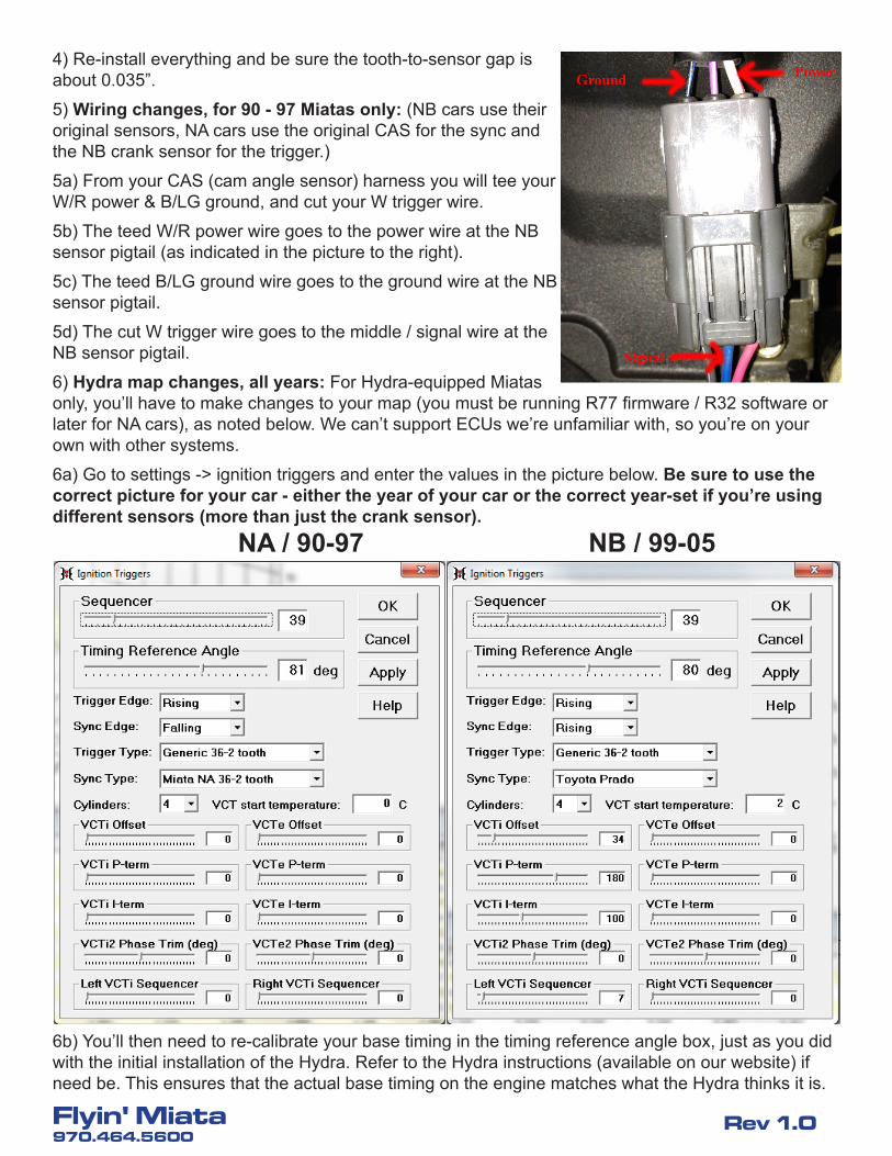
5) Wiring changes, for 90 - 97 Miatas only: (NB cars use their original sensors, NA cars use the original CAS for the sync and the NB crank sensor for the trigger.)
5a) From your CAS (cam angle sensor) harness you will tee your W/R power & B/LG ground, and cut your W trigger wire.
5b) The teed W/R power wire goes to the power wire at the NB sensor pigtail (as indicated in the picture to the right).
5c) The teed B/LG ground wire goes to the ground wire at the NB sensor pigtail.
5d) The cut W trigger wire goes to the middle / signal wire at the NB sensor pigtail.
6) Hydra map changes, all years: For Hydra-equipped Miatas only, you’ll have to make changes to your map (you must be running R77 firmware / R32 software or later for NA cars), as noted below. We can’t support ECUs we’re unfamiliar with, so you’re on your own with other systems.
6a) Go to settings -> ignition triggers and enter the values in the picture below. Be sure to use the correct picture for your car - either the year of your car or the correct year-set if you’re using different sensors (more than just the crank sensor).
NA / 90-97 NB / 99-05
6b) You’ll then need to re-calibrate your base timing in the timing reference angle box, just as you did with the initial installation of the Hydra. Refer to the Hydra instructions (available on our website) if need be. This ensures that the actual base timing on the engine matches what the Hydra thinks it is.
Flyin' Miata970.464.5600
Rev 1.0
6c) For cars with VVT heads only (01 - 05 non-Mazdaspeeds and cars with swapped VVT heads only): If you have a VVT head, you’ll need to calibrate your base VVT using the VCTi offset (and possibly left VCTi sequencer) variable. Refer to the Hydra instructions (available on our website under Product Support) if need be. This ensures that the actual VVT timing on the engine matches what the Hydra thinks it is. If your VVT target at idle RPM (in the engine trimming -> VCTi intake target menu) is not -22, send [email protected] a copy of your map to have it updated.
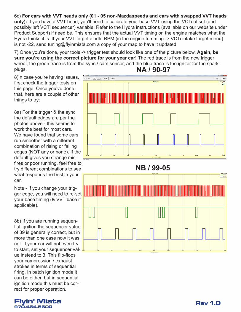
7) Once you’re done, your tools -> trigger test should look like one of the picture below. Again, be sure you’re using the correct picture for your year car! The red trace is from the new trigger wheel, the green trace is from the sync / cam sensor, and the blue trace is the igniter for the spark plugs.
8)In case you’re having issues, first check the trigger tests on this page. Once you’ve done that, here are a couple of other things to try:
NA / 90-97
NB / 99-05
8a) For the trigger & the sync the default edges are per the photos above - this seems to work the best for most cars. We have found that some cars run smoother with a different combination of rising or falling edges (NOT any or none). If the default gives you strange mis-fires or poor running, feel free to try different combinations to see what responds the best in your car.
Note - If you change your trig-ger edge, you will need to re-set your base timing (& VVT base if applicable).
8b) If you are running sequen-tial ignition the sequencer value of 39 is generally correct, but in more than one case now it was not. If your car will not even try to start, set your sequencer val-ue instead to 3. This flip-flops your compression / exhaust strokes in terms of sequential firing. In batch ignition mode it can be either, but in sequential ignition mode this must be cor-rect for proper operation.