Embed Size (px)
Citation preview

On-Load Tap-Changer
for Regulating Transformers
VACUTAP® VRwww.reinhausen.com
AC
HTU
NG
!!
Sei
te w
ird u
m 2
cm
auf
19 c
m v
erkü
rzt
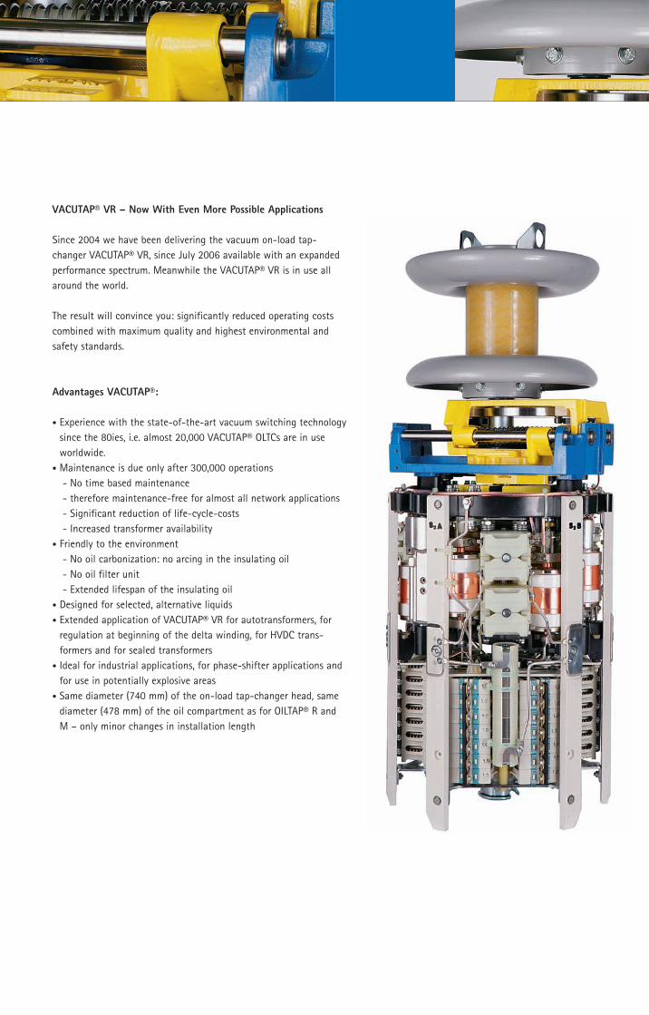
!!VACUTAP® VR – Now With Even More Possible Applications
Since 2004 we have been delivering the vacuum on-load tap-
changer VACUTAP® VR, since July 2006 available with an expanded
performance spectrum. Meanwhile the VACUTAP® VR is in use all
around the world.
The result will convince you: significantly reduced operating costs
combined with maximum quality and highest environmental and
safety standards.
Advantages VACUTAP®:
• Experience with the state-of-the-art vacuum switching technology
since the 80ies, i.e. almost 20,000 VACUTAP® OLTCs are in use
worldwide.
• Maintenance is due only after 300,000 operations
- No time based maintenance
- therefore maintenance-free for almost all network applications
- Significant reduction of life-cycle-costs
- Increased transformer availability
• Friendly to the environment
- No oil carbonization: no arcing in the insulating oil
- No oil filter unit
- Extended lifespan of the insulating oil
• Designed for selected, alternative liquids
• Extended application of VACUTAP® VR for autotransformers, for
regulation at beginning of the delta winding, for HVDC trans-
formers and for sealed transformers
• Ideal for industrial applications, for phase-shifter applications and
for use in potentially explosive areas
• Same diameter (740 mm) of the on-load tap-changer head, same
diameter (478 mm) of the oil compartment as for OILTAP® R and
M – only minor changes in installation length
AC
HTU
NG
!!
Sei
te w
ird u
m 2
cm
auf
19 c
m v
erkü
rzt
!!
0
0
500
1000
1500
2000
2500
3000
3500
4000
4500
VR
C I
II 4
00Y,
VR
C I
I 402, V
RC
I 4
01
VR
C I
II 5
50Y,
VR
C I
I 552, V
RC
I 5
51
VR
C I
II 7
00Y,
VR
C I
I 702,V
RC
I 7
01
VR
D I
II 1
000Y,
VR
C I
1001
VR
F I
2602 2
)
VR
E I
1001
VR
F II
I 1000Y
VR
F I
1001
VR
D I
II 1
300Y
VR
D I
1301
VR
C I
1301
VR
E I
1301
VR
F II
I 1300Y
VR
F I
1301
VR
F II
1302
VR
E I
II 7
00Y,
VR
E I
701
200 400 600 800 1000 1200 1400 1600 1800 2000 2200 2400 2600 2800
1500 kVA
3000 kVA 6000 kVA
Rate
d s
tep v
olt
ages
Ui [ V
]
Rated through-currents Iu [A]
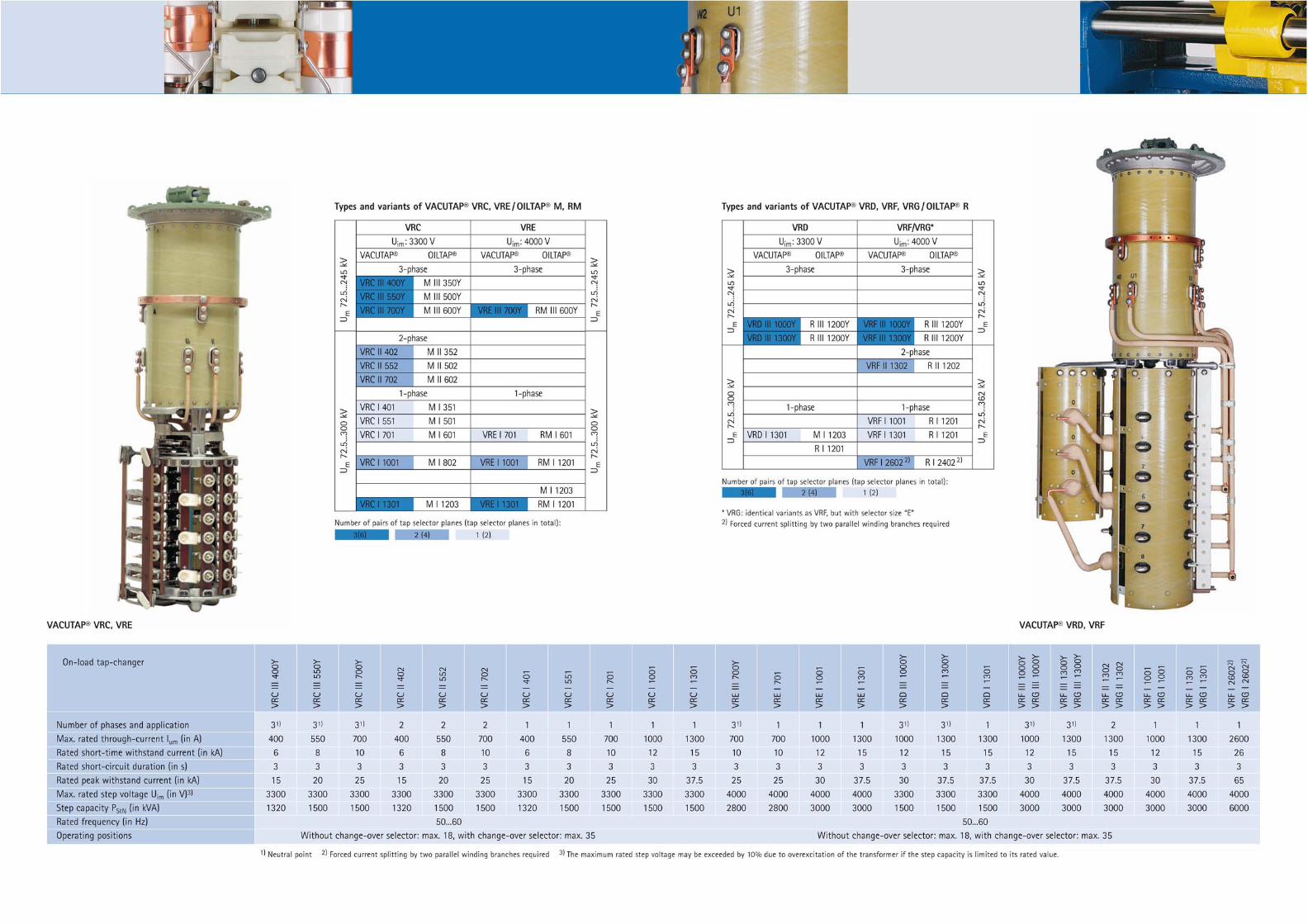
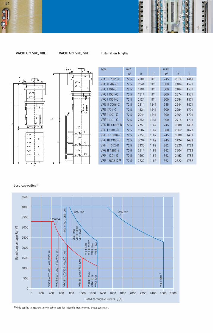
VACUTAP® VRC, VRE VACUTAP® VRD, VRF Installation lengths
Step capacities4)
4) Only applies to network service. When used for industrial transformers, please contact us.
Type min. max.
kV h i kV h i
VRC III 700Y-C 72.5 2184 1111 245 2514 1441
VRC II 702-C 72.5 1944 1111 300 2404 1571
VRC I 701-C 72.5 1704 1111 300 2164 1571
VRC I 1001-C 72.5 1914 1111 300 2374 1571
VRC I 1301-C 72.5 2124 1111 300 2584 1571
VRE III 700Y-C 72.5 2314 1241 245 2644 1571
VRE I 701-C 72.5 1834 1241 300 2294 1701
VRE I 1001-C 72.5 2044 1241 300 2504 1701
VRE I 1301-C 72.5 2254 1241 300 2714 1701
VRD III 1300Y-D 72.5 2758 1162 245 3088 1492
VRD I 1301-D 72.5 1902 1162 300 2362 1622
VRF III 1300Y-D 72.5 2758 1162 245 3088 1492
VRG III 1300-E 72.5 3094 1162 245 3424 1492
VRF II 1302-D 72.5 2330 1162 362 2920 1752
VRG II 1302-E 72.5 2614 1162 362 3204 1752
VRF I 1301-D 72.5 1902 1162 362 2492 1752
VRF I 2602-D 2) 72.5 2232 1162 362 2822 1752
www.reinhausen.com
©Maschinenfabrik Reinhausen GmbH
Falkensteinstrasse 8
93059 Regensburg, Germany
Phone (+49) 9 41/40 90-0
Fax (+49) 9 41/40 90-70 01
E-mail [email protected]
Please note: The data in our publications may differ from the data of devices delivered.
We reserve the right to make changes without notice.
IN206/12 EN – 07/09 – F0081711 · dp · Printed in Germany
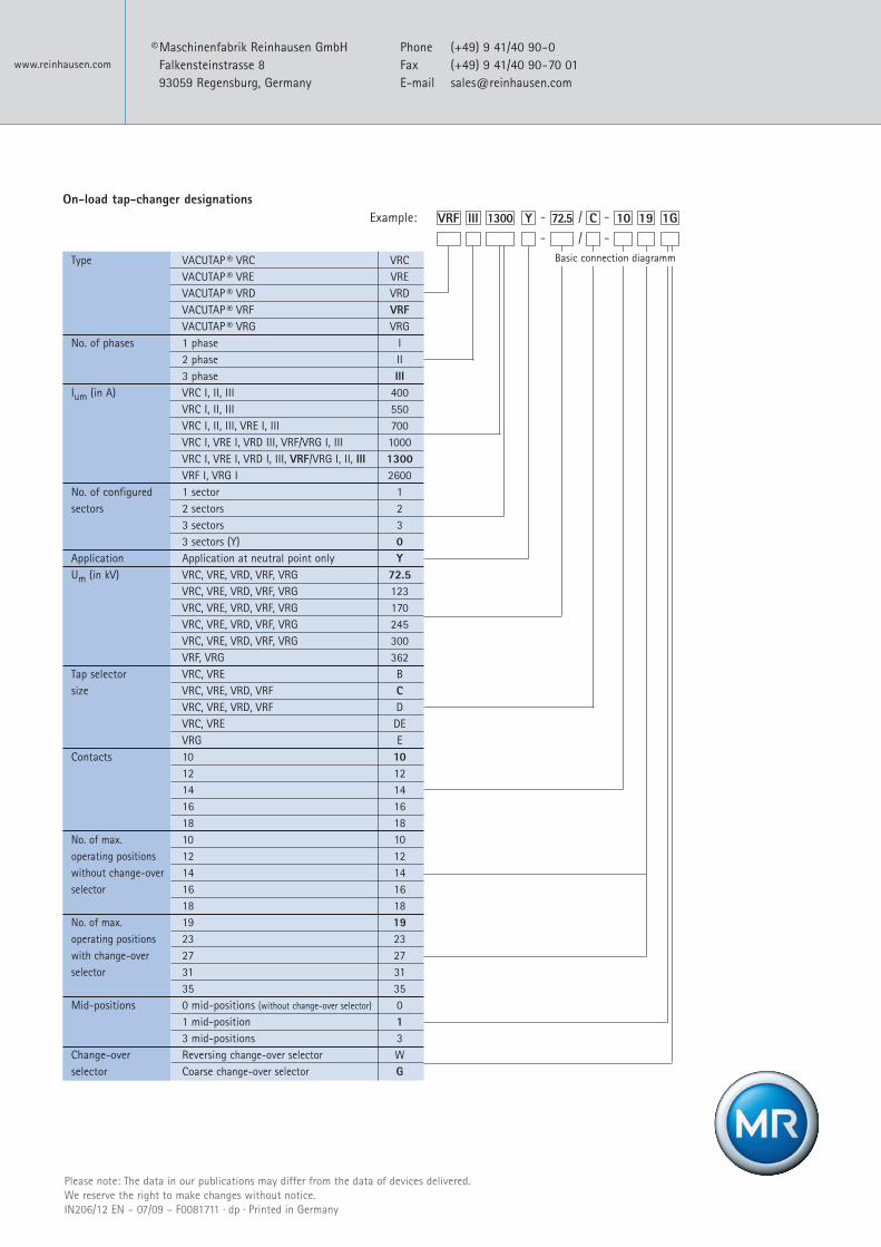
Type VACUTAP ® VRC VRC
VACUTAP ® VRE VRE
VACUTAP ® VRD VRD
VACUTAP ® VRF VRF
VACUTAP ® VRG VRG
No. of phases 1 phase I
2 phase II
3 phase III
Ium (in A) VRC I, II, III 400
VRC I, II, III 550
VRC I, II, III, VRE I, III 700
VRC I, VRE I, VRD III, VRF/VRG I, III 1000
VRC I, VRE I, VRD I, III, VRF/VRG I, II, III 1300
VRF I, VRG I 2600
No. of configured 1 sector 1
sectors 2 sectors 2
3 sectors 3
3 sectors (Y) 0
Application Application at neutral point only Y
Um (in kV) VRC, VRE, VRD, VRF, VRG 72.5
VRC, VRE, VRD, VRF, VRG 123
VRC, VRE, VRD, VRF, VRG 170
VRC, VRE, VRD, VRF, VRG 245
VRC, VRE, VRD, VRF, VRG 300
VRF, VRG 362
Tap selector VRC, VRE B
size VRC, VRE, VRD, VRF C
VRC, VRE, VRD, VRF D
VRC, VRE DE
VRG E
Contacts 10 10
12 12
14 14
16 16
18 18
No. of max. 10 10
operating positions 12 12
without change-over 14 14
selector 16 16
18 18
No. of max. 19 19
operating positions 23 23
with change-over 27 27
selector 31 31
35 35
Mid-positions 0 mid-positions (without change-over selector) 0
1 mid-position 1
3 mid-positions 3
Change-over Reversing change-over selector W
selector Coarse change-over selector G
Example:
On-load tap-changer designations
- / -
III CY - / - 1910VRF 72.51300 1G
Basic connection diagramm