Embed Size (px)
Citation preview

CE1N1410en 11.12.2012 Building Technologies
s 1410
AQR253… AQR254…
Symaro™
Flush-mount room sensor AQR253…AQR254…
• Active flush-mounted room sensor comprising front module, base module and design frame accessory that can be ordered separately
• Operating voltage AC 24 V or DC 15-36 V • Adjustable signal outputs:
DC 0-10 V; DC 2-10 V; DC 0-5 V; DC 0-20 mA; DC 4-20 mA; DC 0-10 mA;
• Maintenance-free CO2 sensing element based on optical infrared absorption measurement (NDIR1))
• VOC2) sensing element based on a heated tin dioxide semi-conductor • Determination of air quality (IAQ3)) by maximum selection from CO2 and
VOC sensing signals • CO2 value indicated by LED • Field of use 0…+50 °C / 0…95 % r.h. (non-condensing) / 0…2000 ppm • Active multi-sensor for CO2-temperature, CO2-humidity, and humidity-
temperature • Passive temperature sensor (LG-Ni1000 / NTC 10k) 1) NDIR = Non-dispersive infrared 2) VOC = Volatile organic compounds 3) IAQ = Indoor air quality
Use
In ventilation and air conditioning plants, to optimize comfort and energy consumption based on demand-controlled ventilation. The room sensor records: • CO2 concentration to indicate presence in smoke-free rooms. • VOC concentration to indicate presence of odors in rooms, e.g. from tobacco
smoke, body odor, material fumes. • Relative humidity in the room. • Temperature in the room.

2/16
Siemens Room sensors AQR253…, AQR254… CE1N1410en Building Technologies 11.12.2012
Typical use: • Measure CO2 and VOC concentration:
In party rooms, foyers, exposition and exhibition halls, canteens, shopping malls, sports facilities, sales rooms, meeting rooms, residential rooms.
• Measure CO2 concentration: In rooms with varying occupancy with regard to time or number of persons, smoke-free rooms such as museums, theaters, movie theaters, lecture halls, offices, classrooms.
Devices for CO2 or VOC measurement are not suited for safety applications such as: Warning against presence of gas or smoke.
Type summary
The mounted sensor comprises a front module, base module with mounting plate as well as design frame that can be ordered separately (see "Accessories"). Product number Stock
number Humidity
measuring range
Temperature measuring
range
Air quality indication
AQR2530NNW S55720-S137 --- --- --- AQR2532NNW S55720-S136 --- 0-50 °C --- AQR2533NNW S55720-S140 0-100 % r.h. --- --- AQR2535NNW S55720-S141 0-100 % r.h. 0-50 °C --- AQR2535NNWQ S55720-S219 0-100 % r.F. 0-50 °C LED AQR2534ANW S55720-S138 0-100 % r.h. 0-50 °C and
LG-Ni1000 ---
AQR2534FNW S55720-S139 0-100 % r.h. 0-50 °C and NTC 10k
---
Product number Stock number CO2 measuring
range VOC measuring
range
AQR2540N…1) --- --- AQR2547N…1) --- 0-100 % AQR2546N…1) 0-2000 ppm 2) --- AQR2548N…1)
Number depends on mounting plate and frame format. See Type summary in the product catalog 0-2000 ppm 2) 0-100 %
1) ASN product number supplement depends on mounting plate format (see table below) 2) ppm = Parts per million
Mounting plate format ASN supplement
CEE/VDE 70.8 x 70.8 mm …F
British Standard
83 x 83 mm …H
3 Modular 110 x 64 mm …G
UL 64 x 110 mm …J
When ordering, provide both name and type reference of the sensor, e.g.: - Room sensor front module: AQR2532NNW / S55720-S136 - Room sensor base module (British Standard): AQR2540NH / S55720-S143
Place a separate order for the design frames AQR2500N…W listed in the "Accessories" section.
Note
Front module
Base module
Ordering

3/16
Siemens Room sensors AQR253…, AQR254… CE1N1410en Building Technologies 11.12.2012
Overview of module combinations and sensor functions
Sensor modules Module types (ASN) Sensor output Relay output 2)
Base module Front module Base module + Front module X1 X2 B, M C, DO
T AQR2540… + AQR2532… --- T T r.h. AQR2540… + AQR2533… r.h. --- r.h. r.h. T AQR2540… + AQR2535… r.h. T r.h. / T r.h. T 1) AQR2540… + AQR2534… r.h. T 1) r.h. / T VOC AQR2547… + AQR2530… VOC --- VOC VOC T AQR2547… + AQR2532… VOC T VOC / T VOC r.h. AQR2547… + AQR2533… VOC r.h. VOC / r.h. VOC r.h. T AQR2547… + AQR2535… VOC r.h. VOC / r.h. / T VOC r.h. T 1) AQR2547… + AQR2534… VOC r.h. 1) VOC / r.h. / T CO2 AQR2546… + AQR2530… CO2 --- CO2 CO2 T AQR2546… + AQR2532… CO2 T CO2 / T CO2 r.h. AQR2546… + AQR2533… CO2 r.h. CO2 / r.h. CO2 r.h. T AQR2546… + AQR2535… CO2 r.h. CO2 / r.h. / T CO2 r.h. T AQR2546… + AQR2535…Q CO2 r.h. CO2 / r.h. / T CO2 r.h. T 1) AQR2546… + AQR2534… CO2 r.h. 1) CO2 / r.h. / T CO2
3) VOC 3) AQR2548… + AQR2530… CO2 IAQ 3) IAQ 3) CO2 VOC T AQR2548… + AQR2532… CO2 T IAQ / T CO2 VOC r.h. AQR2548… + AQR2533… CO2 r.h. IAQ / r.h. CO2 VOC r.h. T AQR2548… + AQR2535… CO2 r.h. IAQ / r.h. / T CO2 VOC r.h. T AQR2548… + AQR2535…Q CO2 r.h. IAQ / r.h. / T CO2 VOC r.h. T 1) AQR2548… + AQR2534… CO2 r.h. 1) IAQ / r.h. / T
Unavailable measuring variables on terminals X1 / X2 1) LG-Ni1000 / NTC 10k 2) Measuring variables and error messages act on the sensor settings (see "Functions) on the relay contact 3) CO2 and VOC measuring variables to determine room air quality (IAQ) by maximum selection
Equipment combinations
All systems and devices capable of processing the following sensor signals: • Active sensor signals:
DC 0-10 V; DC 2-10 V; DC 0/2-10 V; DC 0-5 V; DC 0-20 mA; DC 4-20 mA; DC 0/4-20 mA; DC 0-10 mA;
• Passive sensor signals: For sensors AQR2534… (LG-Ni1000 or NTC 10k)
If sensors are used for: • Min., max., and average calculation, or • Enthalpy, enthalpy difference, absolute humidity and dew point calculation, in
combination with the signal converter SEZ220 (data sheet N5146) recommended.
Accessories
See "Dimensions" for design frame dimensions.
Siemens Design frames
Type Stock number Frame designation (color) Design frame format AQR2510NFW S55720-S158 DELTA line (titanium white) CEE/VDE 80 x 80 mm
AQR2510NHW S55720-S159 DELTA miro (titanium white) British
Standard 90 x 90 mm AQR2510NGW S55720-S160 DELTA azio ( titanium white ) 3 Modular 120 x 80 mm
AQR2510NGW S55720-S160 DELTA azio ( titanium white ) UL 80 x 120 mm

4/16
Siemens Room sensors AQR253…, AQR254… CE1N1410en Building Technologies 11.12.2012
The sensor can be combined with the design frames from the following third manufacturers:
Manufacturer Type
Delta line Delta vita Delta miro
SIEMENS
Delta profil (with intermediate frame) B.1 BERKER B.7
Feller EDIZIOdue + PRESTIGE (with intermediate frame) E2 GIRA Event
Ap581 ALWW A500 (A581 WW)
JUNG
AS500 (AS 581 WW) MERTEN SYSTEM M
We recommend comparing the frame dimensions of third-party frames to the dimensions listed in section "Dimensions".
Functions
The sensor measures the room temperature using a sensing element whose electric resistance changes as a function of the ambient air temperature. The following sensing elements are available depending on the front module (see "Type summary"): • LG-Ni1000 or • NTC 10k Passive output signal on terminals B, M: Resistance values and accuracy depending on the selected sensing element (see diagram below).
Characteristic curve: Accuracy:
R Resistance in Ohm ϑ Temperature in degrees Celsius Δϑ Temperature difference in Kelvin
Third-party design frames
Temperature, passive (AQR2534)
Sensing elements
LG-Ni1000:
NTC 10k

5/16
Siemens Room sensors AQR253…, AQR254… CE1N1410en Building Technologies 11.12.2012
The output signal of the sensors described below is provided either as linear voltage or current signal.
Select the desired output signal (size, range) as per the following table using DIP switches 4, 5, and 6 on the base module.
6 6 DIP switches U [V] I [mA]
5 4
0-10 V 0-20 mA
5 4
2-10 V 4-20 mA
5 4
0/2-10 V 0 V = error message (error)
0/4-20 mA 0 mA = error message (error)
5 4
0-5 V 0-10 mA
The linear output signals on output terminals X1 1) or X2 1) correspond to the following measuring ranges 1)
Output signals / load 2): For measuring ranges 1):
CO2: 0-2000 ppm
VOC: 0-100 % VOC
IAQ: 0-100 % IAQ
r.h.: 0-100 % r.h.
DC 0-10 V DC 2-10 V DC 0-5 V DC 0-20 mA DC 4-20 mA DC 0-10 mA
at max. ±1 mA or at max. ±1 mA or at max. ±1 mA or at 0-500 Ohm or at 0-500 Ohm or at 0-500 Ohm. T: 0-50 °C
1) Depending on measured variable and module combination (see "Type summary")
2) Depending on signal selection (DIP switches 4, 5, and 6)
The sensor measures the room temperature using a sensing element whose electric resistance changes as a function of the ambient air temperature.
Active output signal: For measuring range: On terminal X2, see above for available output signals 0-50 °C 2) Depending on module combination (see "Type summary")
The sensor measures the relative humidity in the room using a humidity sensing element whose electrical capacitance changes as a function of relative humidity.
Active output signal: For measuring range: On terminal X1 3) or X2 3), See above for available output signals
0-100 % r.h.
3) Depending on module combination (see "Type summary")
The sensor uses infrared absorption measurement to determine CO2 concentration in the air (NDIR). The sensor provides exact measurements at all times and does not require maintenance or recalibration thanks to an integrated, stable reference light source.
Active output signal: For measuring range: On terminal X1, see above for available output signals 0-2000 ppm.
The background-lit symbol informs on the current level of CO2 in the room. The colors green / orange / red of the background lighting indicate good / mediocre / poor air quality. The air quality indicator light on green signalises a concentration of ≤1000 ppm, orange ≤1500 ppm, and red exceeding 1500 ppm.
Active sensors
Output signal selection (DIP switches 4, 5, and 6)
DIP switch symbols:: = Switch position left = Switch position right
Output signals and measuring range
Temperature, active (AQR2532,..34,..35)2)
Relative humidity (AQR2533, …34, …35)
CO2 concentration (AQR2546, AQR2548)
Air quality indication
(AQR2535…Q)

6/16
Siemens Room sensors AQR253…, AQR254… CE1N1410en Building Technologies 11.12.2012
The sensor determines the mixed gas concentration (VOC) based on a metal-oxide semiconductor sensing element. The sensor provides exact measurements following a warm-up period and does not require maintenance or recalibration thanks to an integrated compensation mechanism.
Active output signal: For measuring range: On terminal X1, see above for available output signals 0-100 % VOC.
The sensor measures CO2 and VOC concentrations in the air. The greater of the two demand signals (maximum select) is provided as air quality demand (IAQ) for a ventilation controller.
Active output signal: For measuring range: On terminal X2, see above for available output signals 0-100 % IAQ.
10
8
6
4
2
0
0
800
12
00
16
00
40
0
20
00
Max ( ,VOC)CO2
[ppm CO ]2
(*) X2
141
0D0
3
0 40 60
8020
10
0 [% VOC]
[V][mA]20
16.8
13.6
14.4
7.2
4
0 40 60 8020
100
[% IAQ]
max
(*) Sample measuring ranges 4…20 mA and 0…10 V
A potential-free relay contact on the base module (connection terminals C and DO) switches in dependence of selected measuring variable, switching characteristic, and switching setpoint. • Maximum load of relay contacts: AC/DC 30 V, 0.5 A cos φ = 0.5. • The switching circuit is fused externally (≤ 1 A); there is no internal fuse in the
device.
DIP switches 1 and 2 help determine the measured value acting on the relay. Measured variables T, r.h., or CO2/VOC/IAQ are provided depending on the sensor module (see "Type summary" and "Mechanical design").
Measured variables T r.h. CO2/VOC/IAQ 6) DIP switches 1 and 2 2
1 2 1
2 1
6) Depending on the sensor module
Use DIP switch 3 to determine the switching characteristic (NO or NC) for the relay contact.
3 3 Measured value < Switching setpoint Open Closed Measured value > Switching setpoint Closed Open
for missing measured value Open Closed
VOC concentration (AQR2547)
Room air quality (IAQ) (AQR2548 + AQR 2530)
Ventilation demand characteristic curve diagram (output X2)
Potential-free relay contact
Measured value selection (DIP switches 1 and 2)
Switching characteristic selection (DIP switch 3)

7/16
Siemens Room sensors AQR253…, AQR254… CE1N1410en Building Technologies 11.12.2012
The adjustable switching setpoint is located in the center of the switching hysteresis:
Measured variable
Hysteresis
X
CO2 150 ppm 75 ppm
VOC 7.5 % 3.75 %
IAQ 7.5 % 3.75 %
r.h. 5 % 2.5 %
Hysteresis
Switching setpoint T 2.5 K 1.25 K
Read sample: Effective switching value = set switching setpoint − minus "x" for switch-off point (off) or − plus "x" for switch-on point (on).
Rotary selection switch position base module
1 2 3 4 5 6 7 8 9
CO2 800 900 1000 1100 1200 1300 1400 1500 1600 ppm VOC 40 45 50 55 60 65 70 75 80 %VOCIAQ 40 45 50 55 60 65 70 75 80 %IAQr.h. 10 20 30 40 50 60 70 80 90 %r.h.
Switching setpoints of measured variables T 5 10 15 20 25 30 35 40 45 °C DIP switches 1 and 2 and the rotary selection switch allow for implementing the following auxiliary functions:
Auxiliary functions
Rotary selection switch positions
DIP switches 1 and 2
Reset function (Reset 10s) 9 (*) Test function 8 Fault signaling function (Error) 6 Auxiliary functions off (Off) 0
2 1
(*) Switch position 9 for at least 10 seconds.
Rotary selection switch on position 9 for at least 10 seconds: When the front and base modules are assembled during commissioning, the sensor outputs (X1, X2) on the base module automatically assume the active measured values from the existing module types.
Set the rotary selection switch to the ready to operate base module to position 9 for at least 10 seconds to reset the base module to default (factory setting).
Note: Reposition the rotary selection switch from position 9 to the previously set position after activating the reset function. This is the only way to assume new measured variables on the sensor outputs when re-attaching the front module on the base module. Rotary selection switch on position 8: The test function provides a test signal on the base module on sensor outputs (X1, X2) to check the sensor function. The following test signals are provided as per the available sensing elements on the base module: CO2 concentration: 400 ppm VOC concentration: 30% Room air quality IAQ: 40 % Relative humidity: 50 % Temperature: 30 °C
Switching hysteresis
Select relay-switching setpoint (rotary selection switch)
Auxiliary functions (DIP switches 1 and 2 and rotary selection switch)
Reset function (Reset)
Test function
on
off x x

8/16
Siemens Room sensors AQR253…, AQR254… CE1N1410en Building Technologies 11.12.2012
Rotary selection switch on position 6: The relay contact on the base module (connection terminals C and DO) is activated as soon as an error from a sensor is signaled (e.g. in case of a missing or defective sensing element).
Notes: • The fault signaling function does not monitor a passive temperature sensor (e.g.
LG-Ni1000). • The switching function can be inverted using DIP switch 3.
3 3 NO contact NO (normally open)
NC contact NC (normally closed)
The following fault signal is indicated at the associated active sensor output (X1, X2) as soon as a fault occurs (within 10 s) on a sensor module:
Selected, active output signal:
Fault indication signal on defective, active measured value output:
DC 0/2-10V or DC 0/4-20mA
0 V 0 mA.
DC 0-10 V DC 2-10 V DC 0-5 V DC 0-20 mA DC 4-20 mA DC 0-10 mA
For T-sensors: Min. value
0 V 2 V 0 V 0 mA 4 mA 0 mA
For r.h./CO2/VOC sensors: Max. value
10 V 10 V 5 V 20 mA 20 mA 10 mA
Design
The device is designed for flush-mounting. Run the cables from the wall outlet to the sensor base module. The mounted device consists of: • One base module with snapped-on mounting plate • One design frame (ordered as separate accessory) and • One front module.
The sensing elements are located in either the basic or the front module (see "Type summary").
Both models are connected via snap-on device and anti-theft device (red security plug) and can be easily be detached. Use a screwdriver to easily unlock the anti-theft device. Red security plug is including with the front module.
The setting elements DIP switch and rotary selection switch as well as the printed setting aids are available on the base module after removing the front module. See "Functions" for setting variants and their impact on sensor functions.
Fault signal function (Error)
Response to errors
Anti-theft device
Setting and connecting elements
9/16
Siemens Room sensors AQR253…, AQR254… CE1N1410en Building Technologies 11.12.2012
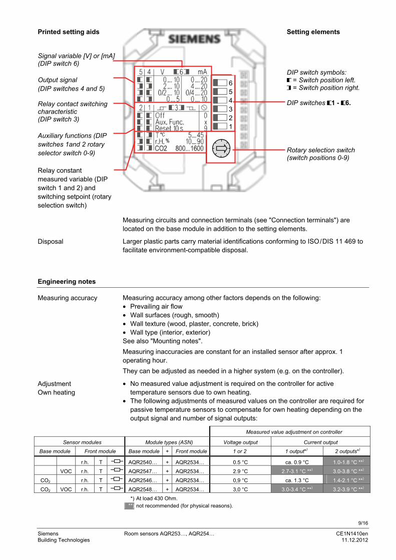
Printed setting aids Signal variable [V] or [mA] (DIP switch 6) Output signal (DIP switches 4 and 5) Relay contact switching characteristic (DIP switch 3) Auxiliary functions (DIP switches 1and 2 rotary selector switch 0-9) Relay constant measured variable (DIP switch 1 and 2) and switching setpoint (rotary selection switch)
Setting elements DIP switch symbols:
= Switch position left. = Switch position right.
DIP switches 1 - 6. Rotary selection switch (switch positions 0-9)
Measuring circuits and connection terminals (see "Connection terminals") are located on the base module in addition to the setting elements.
Larger plastic parts carry material identifications conforming to ISO/DIS 11 469 to facilitate environment-compatible disposal.
Engineering notes
Measuring accuracy among other factors depends on the following: • Prevailing air flow • Wall surfaces (rough, smooth) • Wall texture (wood, plaster, concrete, brick) • Wall type (interior, exterior) See also "Mounting notes".
Measuring inaccuracies are constant for an installed sensor after approx. 1 operating hour.
They can be adjusted as needed in a higher system (e.g. on the controller).
• No measured value adjustment is required on the controller for active temperature sensors due to own heating.
• The following adjustments of measured values on the controller are required for passive temperature sensors to compensate for own heating depending on the output signal and number of signal outputs:
Measured value adjustment on controller
Sensor modules Module types (ASN) Voltage output Current output Base module Front module Base module + Front module 1 or 2 1 output*) 2 outputs*)
r.h. T AQR2540… + AQR2534… 0.5 °C ca. 0.9 °C 1.0-1.8 °C **)
VOC r.h. T AQR2547… + AQR2534… 2.9 °C 2.7-3.1 °C **) 3.0-3.8 °C **)
CO2 r.h. T AQR2546… + AQR2534… 0,9 °C ca. 1.3 °C 1.4-2.1 °C **)
CO2 VOC r.h. T AQR2548… + AQR2534… 3,0 °C 3.0-3.4 °C **) 3.2-3.9 °C **)
*) At load 430 Ohm. **) not recommended (for physical reasons).
Disposal
Measuring accuracy
Adjustment Own heating
654321

10/16
Siemens Room sensors AQR253…, AQR254… CE1N1410en Building Technologies 11.12.2012
A transformer for safety extra-low voltage SELV with separate windings, suited for 100% duty, powers the sensor. Size and fuse the transformer in compliance with local safety regulations. When sizing the transformer, consider the power consumption of the sensor. The data sheets for the devices with which the sensor is wired provide information on how to connect the sensor. Observe maximum permissible cable lengths.
When laying the cables, remember that electrical interference increases with longer, parallel cable runs and smaller distances between cables. Use screened cables for applications in environments exposed to severe electromagnetic interference. Use twisted pair cables for secondary power lines and signal lines.
Longer transmission lines between sensor and signal-processing device can result in measured value deviations. For line impedance > 1 Ohm, we recommend to loop G0 on the device and run it separately to the signal-processing device.
Very high voltage peaks may occur when switching inductive loads (e.g. switching contacts) that may impact device operation. An attenuator switched parallel to the inductive load (e.g. RC element) prevents this.
The present existing switching state remains for a drop off of voltage. As a result, the relay contact cannot be used to monitor voltage.
Mounting notes
Observe the following points when mounting the room sensor: Sensor mounted on interior wall of room to be conditioned: • At ca. 1.5 m height in the room and at least 50 cm from the next wall. • Not on outside walls. • Not in niches or behind curtains. • Not above or near heat sources or shelves. • Not on walls covering heat sources such as a chimney. • Not in the radiation range of heat sources and lighting bodies e.g. spotlights. • Not in areas exposed to direct solar radiation.
Power
Cable routing and cable selection
Potential-free relay contact
Mounting location

11/16
Siemens Room sensors AQR253…, AQR254… CE1N1410en Building Technologies 11.12.2012
Seal the end of the installation conduit to prevent false measurements due to air drafts.
Comply with the various regulations on separating various voltage levels, when mounting the temperature sensor (with low voltage protection) alongside the recessed conduit boxes connected to the low-voltage power. In this case, the mounting frames must be connected to the protective ground wire with a flat plug connector plug and therefore grounded.
1410
J07
Observe the permissible ambient climate (see "Technical data").
Mounting instructions are enclosed in the device package. See the following guideline for more information on mounting the sensor: "Symaro Sensor Installation Guide" Z-F01040501EN.
Commissioning notes
Recommended commissioning procedure: • Check the wiring prior to supplying power. • Set the desired voltage or current output signal using DIP switches, 4, 5, and 6
(see section "Functions", "Output signal selection"). • Briefly plug in the front module on the base module and remove. As a result, the
sensor outputs (X1, X2) on the base module also take over the active measured variables of the existing module types (see also "Functions", "Reset function").
• Activate the test function on position 8 using the rotary selection switch. A test signal is provided on sensor outputs (X1, X2) to test the sensor functions (see "Functions", "Test function").
• Deactivate the test function as well as an other auxiliary function using DIP switches 1 to 3 as needed, and activate using the rotary selection switch (see "Functions", "Auxiliary functions").
• Install anti-theft protection (red security plug) on the base module as needed. • Mount the design frame on the mounting plate on the base module and plug in
the front module.
Mounting instructions

12/16
Siemens Room sensors AQR253…, AQR254… CE1N1410en Building Technologies 11.12.2012
Technical data
Operational voltage (SELV) AC 24 V ±20 % or DC15…36 V Frequency 50 /60 Hz at AC 24 V Total power consumption (front and base module)
Devices without VOC (AQR2540N…, AQR2546N…)
Devices with VOC (AQR2547N…, AQR2548N…)
At "U" output signal: "I" output signal: < 0.5 VA < 1.5 VA < 1.5 VA < 2.5 VA
Relay type Max. switching voltage / Max. nominal current Fuse Response on voltage failure
Bistable AC/DC 30 V, 0.5 A cos φ = 0.5 external, max. 1 A (slow) No change of state.
Permissible line length See data sheet of the signal processing device
Measuring range 0-2000 ppm. Measuring accuracy at 23 °C and 1013 hPa ≤ ± (50 ppm + 2 % of measured value). Temperature dependency ±2 ppm / °C typical Pressure dependency 0,14 % of measured value / hPa Long-term drift ≤ ±20 ppm per year Time constant t63 <5 min Active output signal, connection X1 Select output signal: See "Functions". Potential-free relay contact, connections: C and DO Switching setpoint selection: See "Functions" Recalibration-free For at least 8 years Measuring range 0-100 % VOC. Note on measuring accuracy (see also "Engineering notes")
Warm-up time: ca. 20 minutes Initial self-acting calibration after 8 hours operation
Time constant t63 VOC <3.5 min Active output signal, connection X1 Select output signal: See "Functions". Potential-free relay contact, connections: C and DO Switching setpoint selection: See "Functions" Measuring range Max. selection from CO2 and VOC
Weighting: 100 % VOC 2000 ppm CO2 Active output signal, connection X2 Select output signal: See "Functions". Potential-free relay contact, connections: C and DO Switching setpoint selection: See "Functions" Measuring range 0-100 % r.h. Field of use 0-95 % r.h. (non-condensing) Measuring accuracy at 25 °C
20-80 % r.h. 0-95 % r.h.
±3 % r.h. ±5 % r.h.
Time constant 20 s Active output signal, connection X1 or X2 depending on module type (see "Type summary")
Select output signal: See "Functions".
Potential-free relay contact, connections: C and DO Switching setpoint selection: See "Functions" Measuring range 0-50 °C Measuring accuracy at AC 24 V for
25 °C 5-30 °C
<±0.25 K (temperature sensor) < ±0.5 K (at output signal 0…10 V) < ±0.6 K (at output signal 4…20 mA)
Time constant t63 Ca. 13 min Active output signal, connection X2 Select output signal: See "Functions". Potential-free relay contact, connections: C and DO Switching setpoint selection: See "Functions" Sensing elements Depending on front module (see "Type
summary") NTC 10k (B=3988) or LG-Ni1000. Measuring range 0-50 °C (detailed data see "Functions") Time constant t63 Ca. 13 min Adjustment for own heating See "Engineering notes". Output signal (terminals B, M) Passive Degree of protection of housing to IEC 60529 IP 30 with front module
IP 20 without front module Protection class III as per EN 60730 Screw terminals for 1 × 0.25...2.5 mm2 (wire / strand)
2 × 0.25...1.5 mm2 (wire / strand)
Power
Potential-free relay contact
Line length for measuring sign.
Function data CO2
(AQR2546, AQR2548)
Function data VOC (AQR2547)
Functional data (IAQ) (AQR2548 + AQR 2530)
Function data r.h. (AQR2533, …34, …35)
Function data temperature active (AQR2532, ..34 1), 35 1))
Function data temperature passive (AQR2534)
Degree of protection
Electrical connection

13/16
Siemens Room sensors AQR253…, AQR254… CE1N1410en Building Technologies 11.12.2012
Operation as per Climatic conditions Temperature (housing and electronics) Humidity Mechanical conditions
IEC 60721-3-3 Class 3K3 0 -50 °C 0-95% r. h. (non-condensing) Class 3M2.
Transport as per Climatic conditions Temperature Humidity Mechanical conditions
IEC 60721-3-2 Class 2K3 −25...+70 °C <95 % r.h. Class 2M2
Top part of front module ASA + PC titan white (similar to RAL9010). Lower part of front module Housing parts of base module
PC light-gray RAL 7035 PC light-gray RAL 7035.
Anti-theft device POM bright red RAL 3000. Siemens Design frames ASA + PC titan white (similar to RAL9010). Mounting plate Steel Sensor, total Silicone-free Packaging Corrugated cardboard Product standard
Automatic electrical controls devices for household and similar use
EN 60730-1
Electromagnetic compatibility
Immunity Emissions
EN 61000-6-1 / EN 61000-6-2 EN 61000-6-3
conformity as per EMC directive 2004/108/EC
conformity emissions AS/NZS 61000-6-3 The product environmental declaration CE1E1410en contains data on environmentally compatible product design and assessments (RoHS compliance, materials composition, packaging, environmental benefit, disposal)
ISO 14001 (Environment) ISO 9001 (Quality) SN 36350 (Environmentally compatible products) RL 2002/95/EG (RoHS)
Including packaging, depending on the module type Front module Base module
between 30 – 50 g between 60 – 100 g.
1) Possible module combination, see "Type summary".
Environmental conditions
Materials and colors
Standards, guidelines
Environmental compatibility
Dimensions (weight)

14/16
Siemens Room sensors AQR253…, AQR254… CE1N1410en Building Technologies 11.12.2012
Connection terminals
Dimensions (in mm)
70.8
70.8
45 14
10
M0
239
55
70.8
55
70.8
13.5
12.5 38
50.5
47
141
0M
01
Base module
Front and base module (assembled without design frame)
Relay contact (SELV)
System potential AC 24 V (SELV) or DC 15-36 V System neutral/Measuring neutral
Passive sensor output
(LG-Ni1000 / NTC 10k)
Active sensor outputs (T / r.h. / CO2 / VOC / IAQ)

15/16
Siemens Room sensors AQR253…, AQR254… CE1N1410en Building Technologies 11.12.2012
Mounting plate and design frame
Mounting plate "CEE/VDE" (square):
DELTA line design frame:
Mounting plate "British standard" (square):
DELTA miro design frame:
83
30
68
836
84
8.5
11
13
141
0M
03
Mounting plate "3 Modular" (landscape): Design frames "DELTA azio":
Mounting plate "UL" (portrait): Design frame "DELTA azio": Dimensions same as for mounting plate "3 Modular" (see above), but portrait format
Dimensions same as for design frame "DELTA azio" (see above), but portrait format

16/16
Siemens Room sensors AQR253…, AQR254… CE1N1410en Building Technologies 11.12.2012
2011-2012 Siemens Switzerland Ltd. Subject to changes