Embed Size (px)
Citation preview
G AT E F R A M E
F E N C E P O S T
G AT E G AT E G AT E
90˚
90˚
G AT E F R A M E
F E N C E P O S T
G AT E G AT E G AT E
90˚
90˚
G AT E F R A M E
F E N C E P O S T
G AT E G AT E G AT E
90˚
90˚
G AT E F R A M E
F E N C E P O S T
G AT E G AT E G AT E
90˚
90˚
G AT E F R A M E
F E N C E P O S T
G AT E G AT E G AT E
90˚
90˚
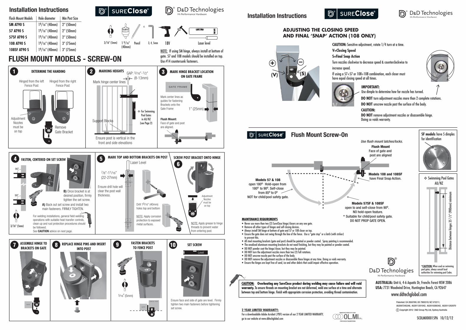
FLUSH MOUNT MODELS - SCREW-ON
GATE FRAME
FENCE POST
GATEGATEGATE
90˚
90˚
Flush Mount Models Hole diameter Min Post Size
SM AT90 S 19/16” (40mm) 2” (50mm)
57 AT90 S 19/16” (40mm) 2” (50mm)
57SF AT90 S 19/16” (40mm) 2” (50mm)
108 AT90 S 19/16” (40mm) 3” (75mm)
108SF AT90 S 19/16” (40mm) 3” (75mm) NOTE: If using SM hinge, always install at bottom of gate. 57 and 108 models should be installed on top. Use #14 countersunk fasteners.
3, 4, 5mm1 9/16” (40mm)
18V Laser level
F E N C E P O S T
G AT E
90˚
90˚
F E N C E P O S TF E N C E P O S T
DETERMINE THE HANDING
Adjustment Nozzlesmust be on top
Hinged from the leftFence Post
Hinged from the right Fence Post
Remove Gate Bracket
F E N C E P O S T
G AT E
90˚
90˚
F E N C E P O S TF E N C E P O S T
Mark hinge center lines
MARKING HEIGHTS GAP: 5/16”-1/2” (8-13mm)
Support Blocks
Ensure post is vertical in the front and side elevations
MARK HINGE BRACKET LOCATION ON GATE FRAME
Mark center lines as guides for fastening Brackets onto the Gate Frame 1” (25mm)
FASTEN, CENTERED ON SET SCREW
A) Back out set screw and install two main fasteners. FIRMLY TIGHTEN.
F E N C E P O S T
G AT E
90˚
90˚
F E N C E P O S TF E N C E P O S T
F E N C E P O S T
G AT E
90˚
90˚
F E N C E P O S TF E N C E P O S T
MARK TOP AND BOTTOM BRACKETS ON POST
Ensure drill hole will clear the post wall thickness.
7/8”-11/16” (22-27mm)
Laser Level
F E N C E P O S T
G AT E
90˚
90˚
F E N C E P O S TF E N C E P O S T
Drill 19/16” (40mm) holes top and bottom
NOTE: Apply corrosion protection to exposed metal surfaces.
SCREW POST BRACKET ONTO HINGE
ASSEMBLE HINGE TO BRACKETS ON GATE
G AT E F R A M E
F E N C E P O S T
G AT E G AT E G AT E
90˚
90˚
GATE FRAME
FENCE POST
GATEGATEGATE
90˚
90˚
REPLACE HINGE PINS AND INSERT INTO POST
FASTEN BRACKETS TO FENCE POST
1 2 3
4 56
7 8 9 10 SET SCREW
Ensure face and side of gate are level. Firmly tighten two main fasteners before tightening set screw.
SUREClose®
Hi-Performance HardwareInstallation Instructions
B) Once bracket is at desired position, firmly tighten the set screw.
3/16” (5mm)
Flush Mount:Face of gate and post are aligned.
3/16” (5mm)
3/16” (5mm)
Pencil
NOTE: Apply grease to hinge threads to prevent water from entering post.
Level
(V)
+ –
(S)
ADJUSTING THE CLOSING SPEED AND FINAL ‘SNAP’ ACTION (108 ONLY)
SUREClose®
Installation Instructions Hi-Performance Hardware
CAUTION: Sensitive adjustment, rotate 1/4 turn at a time.V=Closing SpeedS=Final Snap ActionTurn nozzles clockwise to decrease speed & counterclockwise to increase speed.
IMPORTANT: Use dimple to determine how far nozzle has turned.
DO NOT turn adjustment nozzles more than 2 complete rotations.DO NOT unscrew nozzle past the surface of the body.CAUTION: DO NOT remove adjustment nozzles or disassemble hinge. Doing so voids warranty.
If using a 57+57 or 108+108 combination, each closer must have equal closing speed at all times.
Models 57SF & 108SFopen to and self-close from 90o.
NO hold-open feature.* Suitable for child/pool safety gate.
DO NOT PROP GATE OPEN.
Models 57 & 108open 180o. Hold-open from
180o to 90o. Self-closefrom 85o to 0o
NOT for child/pool safety gate.
Models 108 and 108SFhave Final Snap Action.
Flush MountFace of gate and post are aligned
Use flush mount latches/locks.
SCOLM000015PA 10/12/12
MAINTENANCE REQUIREMENTS• Never use more than two (2) SureClose hinge/closers on any one gate. • Remove all other types of hinges and self-closing devices. • Always install SM hinge at bottom of gate and 57 or 108 closer on top. • Ensure the gate does not swing through the line of the fence. Use a “gate stop” or a latch (with striker) to prevent this.• All steel mounting brackets (gate and post) should be painted or powder coated. Spray painting is recommended.• The anodized aluminum mounting brackets do not need finishing, but they may be painted or powder coated. • DO NOT powder coat the hinge/closer, but they may be painted. • DO NOT turn the adjustment nozzles more than two (2) full rotations. • DO NOT unscrew nozzle past the surface of the body.• DO NOT remove the adjustment nozzles or disassemble these hinges at any time. Doing so voids warranty.• Ensure the hinges are kept free of sand, ice and other debris that could impair effective operation.
*CAUTION: When used on swimming pool gates, always consult local authorities for swimming pool Codes.
SF models have 5 dimples for identification
SUREClose® Flush Mount Screw-On
Dista
nce b
etwee
n hing
es 3
5 1 /
2” (9
00mm
) mini
mum
v Swimming Pool GatesAU/NZ
v For Swimming Pool Gatesin AU/NZ
(see Page 2)
AUSTRALIA: Unit 6, 4-6 Aquatic Dr, Frenchs Forest NSW 2086USA: 7731 Woodwind Drive, Huntington Beach, CA 92647
www.ddtechglobal.com
2 YEAR LIMITED WARRANTY: For a downloadable Adobe Acrobat (.PDF) version of our 2 YEAR LIMITED WARRANTY, go to our website at www.ddtechglobal.com
MANUFACTURED BY OLMI
PRECISION ENGINEERING
CAUTION: Overheating any SureClose product during welding may cause failure and will void warranty. To ensure threads on mounting bracket are not deformed, weld one surface at a time and alternate between top and bottom hinge. Finish with appropriate corrosion protection, avoiding thread contamination.
For welding installations, general field welding operations with suit able heat transfer controls, clean up and rust protection procedures should be followed. See CAUTION advice on next page.
Copyright 2012 D&D Group Pty Ltd, Sydney Australia
Patented: CA 2650769; US 7900319; NZ 573211;
AU2007245248, AU2011201042, AU2010280342, AU2011202070
Para instalacion por soldando, operaciones general de soldando en campo con controles adecuados de transferencia de calor, limpieza y procedimientos de óxido protectoin se deben seguir. Ver consejo de ADVERTENCIA en la pagina proximo.
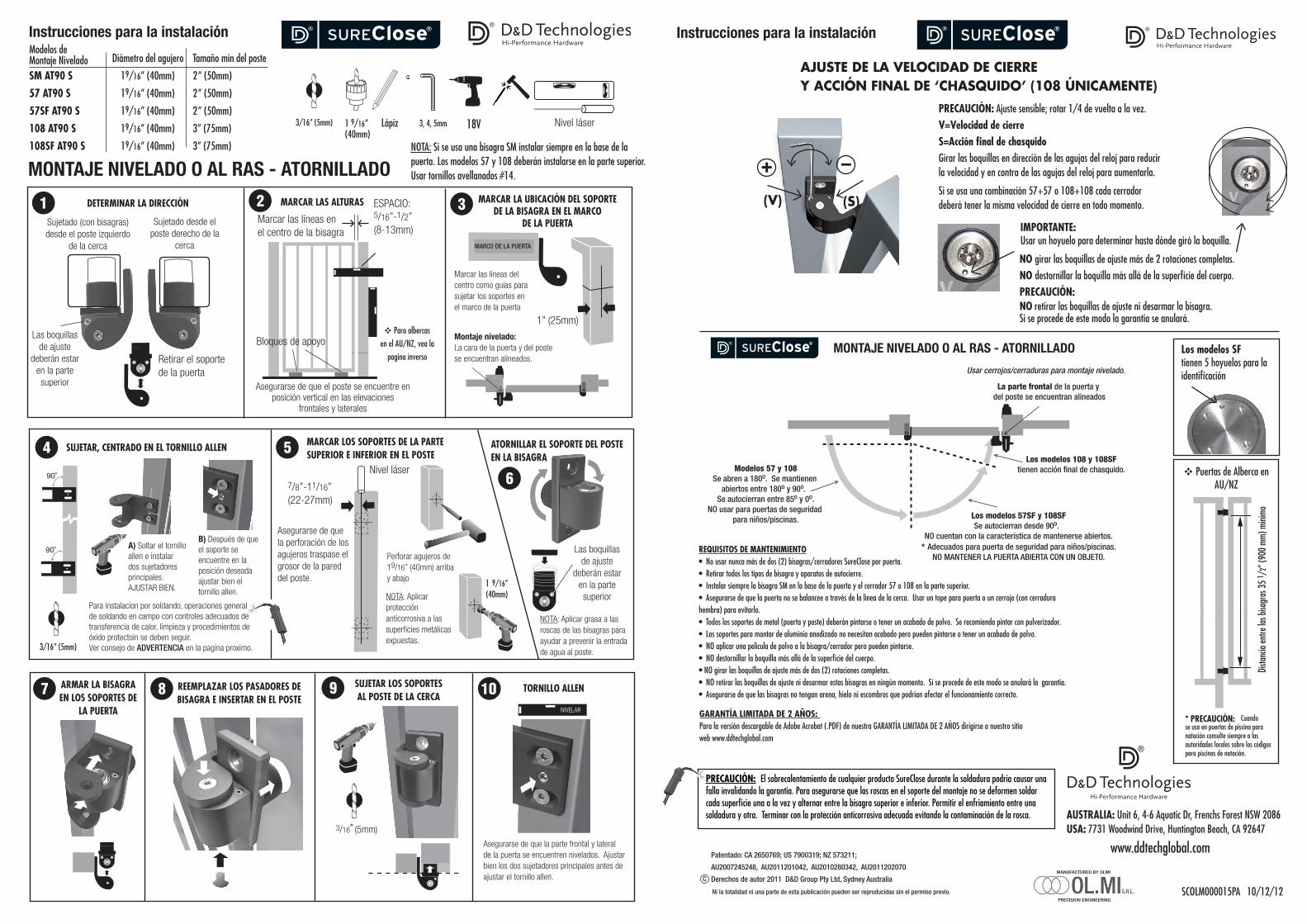
NOTA: Si se usa una bisagra SM instalar siempre en la base de la puerta. Los modelos 57 y 108 deberán instalarse en la parte superior.Usar tornillos avellanados #14.
Instrucciones para la instalación
Los modelos 57SF y 108SFSe autocierran desde 90o.
NO cuentan con la característica de mantenerse abiertos.* Adecuados para puerta de seguridad para niños/piscinas.
NO MANTENER LA PUERTA ABIERTA CON UN OBJETO.
Modelos 57 y 108Se abren a 180o. Se mantienen
abiertos entre 180o y 90o. Se autocierran entre 85o y 0o.
NO usar para puertas de seguridad para niños/piscinas.
Los modelos 108 y 108SFtienen acción final de chasquido.
La parte frontal de la puerta y del poste se encuentran alineados
Usar cerrojos/cerraduras para montaje nivelado.
SUREClose®
(V)
+ –
(S)
AJUSTE DE LA VELOCIDAD DE CIERREY ACCIÓN FINAL DE ‘CHASQUIDO’ (108 ÚNICAMENTE)
SUREClose®Instrucciones para la instalaciónHi-Performance Hardware
Los modelos SF tienen 5 hoyuelos para la identificación
PRECAUCIÓN: Ajuste sensible; rotar 1/4 de vuelta a la vez.V=Velocidad de cierreS=Acción final de chasquidoGirar las boquillas en dirección de las agujas del reloj para reducir la velocidad y en contra de las agujas del reloj para aumentarla.
IMPORTANTE: Usar un hoyuelo para determinar hasta dónde giró la boquilla.
NO girar las boquillas de ajuste más de 2 rotaciones completas.NO destornillar la boquilla más allá de la superficie del cuerpo.PRECAUCIÓN: NO retirar las boquillas de ajuste ni desarmar la bisagra. Si se procede de este modo la garantía se anulará.
Si se usa una combinación 57+57 o 108+108 cada cerrador deberá tener la misma velocidad de cierre en todo momento.
SCOLM000015PA 10/12/12
REQUISITOS DE MANTENIMIENTO• No usar nunca más de dos (2) bisagras/cerradores SureClose por puerta. • Retirar todos los tipos de bisagra y aparatos de autocierre. • Instalar siempre la bisagra SM en la base de la puerta y el cerrador 57 o 108 en la parte superior.• Asegurarse de que la puerta no se balancee a través de la línea de la cerca. Usar un tope para puerta o un cerrojo (con cerradura hembra) para evitarlo.• Todos los soportes de metal (puerta y poste) deberán pintarse o tener un acabado de polvo. Se recomienda pintar con pulverizador.• Los soportes para montar de aluminio anodizado no necesitan acabado pero pueden pintarse o tener un acabado de polvo. • NO aplicar una película de polvo a la bisagra/cerrador pero pueden pintarse.• NO destornillar la boquilla más allá de la superficie del cuerpo.• NO girar las boquillas de ajuste más de dos (2) rotaciones completas. • NO retirar las boquillas de ajuste ni desarmar estas bisagras en ningún momento. Si se procede de este modo se anulará la garantía.• Asegurarse de que las bisagras no tengan arena, hielo ni escombros que podrían afectar el funcionamiento correcto.
AUSTRALIA: Unit 6, 4-6 Aquatic Dr, Frenchs Forest NSW 2086USA: 7731 Woodwind Drive, Huntington Beach, CA 92647
www.ddtechglobal.com
GARANTÍA LIMITADA DE 2 AÑOS: Para la versión descargable de Adobe Acrobat (.PDF) de nuestra GARANTÍA LIMITADA DE 2 AÑOS dirigirse a nuestro sitio web www.ddtechglobal.com
* PRECAUCIÓN: Cuando se usa en puertas de piscina para natación consulte siempre a las autoridades locales sobre los códigos para piscinas de natación.
MANUFACTURED BY OLMI
PRECISION ENGINEERING
G AT E F R A M E
F E N C E P O S T
G AT E G AT E G AT E
90˚
90˚
G AT E F R A M E
F E N C E P O S T
G AT E G AT E G AT E
90˚
90˚
G AT E F R A M E
F E N C E P O S T
G AT E G AT E G AT E
90˚
90˚
G AT E F R A M E
F E N C E P O S T
G AT E G AT E G AT E
90˚
90˚
G AT E F R A M E
F E N C E P O S T
G AT E G AT E G AT E
90˚
90˚
MONTAJE NIVELADO O AL RAS - ATORNILLADO
GATE FRAME
FENCE POST
GATEGATEGATE
90˚
90˚
Diámetro del agujero Tamaño mín del poste
SM AT90 S 19/16” (40mm) 2” (50mm)
57 AT90 S 19/16” (40mm) 2” (50mm)
57SF AT90 S 19/16” (40mm) 2” (50mm)
108 AT90 S 19/16” (40mm) 3” (75mm)
108SF AT90 S 19/16” (40mm) 3” (75mm)
3, 4, 5mm1 9/16” (40mm)
18V
F E N C E P O S T
G AT E
90˚
90˚
F E N C E P O S TF E N C E P O S T
DETERMINAR LA DIRECCIÓN
Las boquillas de ajuste
deberán estar en la parte superior
Sujetado (con bisagras) desde el poste izquierdo
de la cerca
Sujetado desde el poste derecho de la
cerca
Retirar el soporte de la puerta
F E N C E P O S T
G AT E
90˚
90˚
F E N C E P O S TF E N C E P O S T
Marcar las líneas en el centro de la bisagra
MARCAR LAS ALTURAS ESPACIO: 5/16”-1/2” (8-13mm)
Asegurarse de que el poste se encuentre en posición vertical en las elevaciones
frontales y laterales
MARCAR LA UBICACIÓN DEL SOPORTE DE LA BISAGRA EN EL MARCO
DE LA PUERTA
Marcar las líneas del centro como guías para sujetar los soportes en el marco de la puerta
1” (25mm)
SUJETAR, CENTRADO EN EL TORNILLO ALLEN
A) Soltar el tornillo allen e instalar dos sujetadores principales. AJUSTAR BIEN.
F E N C E P O S T
G AT E
90˚
90˚
F E N C E P O S TF E N C E P O S T
F E N C E P O S T
G AT E
90˚
90˚
F E N C E P O S TF E N C E P O S T
MARCAR LOS SOPORTES DE LA PARTE SUPERIOR E INFERIOR EN EL POSTE
Asegurarse de que la perforación de los agujeros traspase el grosor de la pared del poste.
7/8”-11/16” (22-27mm)
Nivel láser
F E N C E P O S T
G AT E
90˚
90˚
F E N C E P O S TF E N C E P O S T
Perforar agujeros de 19/16” (40mm) arriba y abajo
NOTA: Aplicar protección anticorrosiva a las superficies metálicas expuestas.
ATORNILLAR EL SOPORTE DEL POSTE EN LA BISAGRA
ARMAR LA BISAGRA EN LOS SOPORTES DE
LA PUERTA
G AT E F R A M E
F E N C E P O S T
G AT E G AT E G AT E
90˚
90˚
GATE FRAME
FENCE POST
GATEGATEGATE
90˚
90˚
REEMPLAZAR LOS PASADORES DE BISAGRA E INSERTAR EN EL POSTE
SUJETAR LOS SOPORTES AL POSTE DE LA CERCA
1 2 3
4 5
6
7 8 9 10 TORNILLO ALLEN
Asegurarse de que la parte frontal y lateral de la puerta se encuentren nivelados. Ajustar bien los dos sujetadores principales antes de ajustar el tornillo allen.
SUREClose®
Hi-Performance Hardware
B) Después de que el soporte se encuentre en la posición deseada ajustar bien el tornillo allen.
3/16” (5mm)
Montaje nivelado:La cara de la puerta y del poste se encuentran alineados.
3/16” (5mm)
NIVELAR
Bloques de apoyo
MARCO DE LA PUERTA
Nivel láser
Las boquillas de ajuste
deberán estar en la parte superior
NOTA: Aplicar grasa a las roscas de las bisagras para ayudar a prevenir la entrada de agua al poste.
Ni la totalidad ni una parte de esta publicación pueden ser reproducidas sin el permiso previo.
MONTAJE NIVELADO O AL RAS - ATORNILLADO
1 9/16”(40mm)
Lápiz
Modelos de Montaje Nivelado
Dista
ncia
entre
las b
isagr
as 3
5 1 /
2” (9
00 m
m) m
ínimo
v Puertas de Alberca en AU/NZ
v Para albercas en el AU/NZ, vea la
pagina inverso
PRECAUCIÓN: El sobrecalentamiento de cualquier producto SureClose durante la soldadura podría causar una falla invalidando la garantía. Para asegurarse que las roscas en el soporte del montaje no se deformen soldar cada superficie una a la vez y alternar entre la bisagra superior e inferior. Permitir el enfriamiento entre una soldadura y otra. Terminar con la protección anticorrosiva adecuada evitando la contaminación de la rosca.
Patentado: CA 2650769; US 7900319; NZ 573211;
AU2007245248, AU2011201042, AU2010280342, AU2011202070
Derechos de autor 2011 D&D Group Pty Ltd, Sydney Australia
3/16” (5mm)