Embed Size (px)
Citation preview
aerospaceclimate controlelectromechanicalfiltrationfluid & gas handlinghydraulicspneumaticsprocess controlsealing & shielding
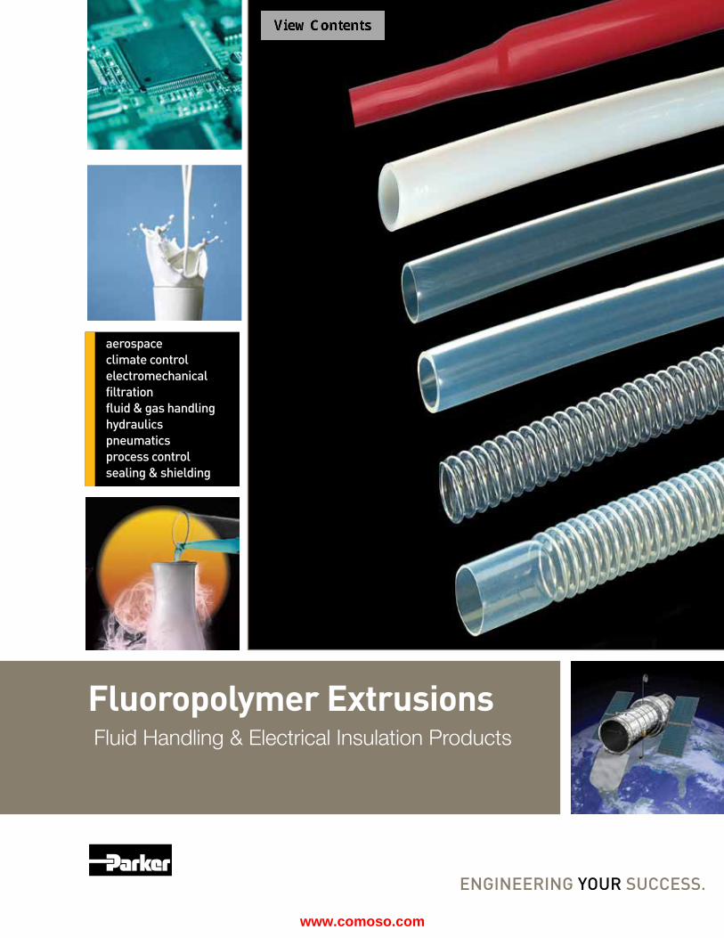
Fluid Handling & Electrical Insulation Products
Fluoropolymer Extrusions
www.comoso.com

www.comoso.com
Table of Contents
Fluoropolymer Tubing Overview .............................................................................................................................................1-16 Properties .......................................................................................................................................................................4 Convoluted .....................................................................................................................................................................6 Heatshrink ......................................................................................................................................................................9
Nomenclature ...............................................................................................................................................................14
PFA Products High Purity PFA Smoothbore Tubing ................................................................................................................A02-A03 PFA Smoothbore Tubing...... ..............................................................................................................................A04-A05 Corrugated Tubing .................................................................................................................................................... B14 Retractable Coiled Tubing ........................................................................................................................................ B16
FEP Products Smoothbore Tubing............................................................................................................................................B01-B05 Heat Shrink Tubing
1.3:1 Fractional .................................................................................................................................................... B04 1.3:1 AWG ............................................................................................................................................................ B05 1.67:1 ................................................................................................................................................................... B06
Rollcover ............................................................................................................................................................ B08 Double Shrink ...................................................................................................................................................... B09
Convoluted Tubing FEP Convoluted .................................................................................................................................................. B10 Convo-Flon™ ........................................................................................................................................................ B10 SAE AS81914/3 ................................................................................................................................................... B12
Corrugated Tubing .................................................................................................................................................... B14 Retractable Coiled Tubing ........................................................................................................................................ B16
PTFE Products Smoothbore Tubing
AWG ............................................................................................................................................................. C08-C12 Fractional ...................................................................................................................................................C02-C03, C06 Metric ..................................................................................................................................................................... C02 Beading ..................................................................................................................................................................... C13 Spiral Wrap Tubing .................................................................................................................................................... C14 Heat Shrink Tubing 2:1 Fractional ....................................................................................................................................................... C16
2:1 AWG ............................................................................................................................................................... C18 4:1 Fractional ....................................................................................................................................................... C22 Convoluted Tubing
Convo-Tex® .......................................................................................................................................................... C24 Low Profile ........................................................................................................................................................... C26 Heavy Wall ........................................................................................................................................................... C26 SAE AS81914/1 ................................................................................................................................................... C28
PVDF Products Smoothbore Tubing................................................................................................................................................... D02
ETFE Products Heat Shrink Tubing 1.5:1 ............................................................................................................................................E02
Convoluted SAE AS81914/5 ......................................................................................................................................E04
Technical ..................................................................................................................................................................................F01
Warranty ...................................................................................................................................................................................F07
Offer of Sale .............................................................................................................................................................................F11
www.comoso.com
Intro
PFA
Tu
bing
A
FEP
Tu
bing
B
PVD
F
Tubi
ng
D
PTFE
Tu
bing
C
Index
G
Tech
nica
l Pa
ges
F
ETFE
Tu
bing
E
Fluoropolymer Tubing
TexLoc Facility Fort Worth, Texas
Parflex DivisionRavenna, Ohio
The Parflex Division's fluoropolymer tubing operation, located at Parker TexLoc in Fort Worth, TX, specializes in the development and extrusion of fluoropolymer tubing for fluid handling applications. These products operate in high temperature applications up to 500°F (260°C) and in cryogenic ap-plications with temperatures as low as -100°F (-75°C).
TexLoc extrusions are resistant to UV radiation and moisture while offering the lowest coefficient of friction of any
material available. Additionally, all of the tubing products are made from resins and colors that are certified to be free of mercury, heavy metals and other materials that are restricted in accordance with the RoHS directive. In fact, the quality engineered into our products makes them suitable for critical applications in the medical, pharmaceutical and instrumentation markets.
All of the tables in this catalog are supplied with inch and mm sizes.
Working pressure is calculated at 73˚F (23°C) using a Design Factor of 4 to 1. Special sizes, profiles, cut lengths and minimum continuous lengths are also available upon request.
Thank you for allowing us to serve your fluoropolymer needs.
Parflex PTFE, FEP, PFA and PVDF tubing complies with European Standard RoHs and are also FDA compliant to FDA regulation 21 CFR 177.1550, making these products suitable for use in food and beverage applications.
Parflex PTFE, FEP and PFA are listed VW-1 in the burning test for Underwriters Laboratories and pass the UL-83 vertical flame test. In a flame situation, PTFE, FEP and PFA tubing resist combustion and do not promote flame spread.
Parker Hannifin Corporation | Parflex® Division, TexLoc | Fort Worth, Tx | www.texloc.com
For detailed ordering information, please consult price list or contact Parker Texloc.
2
www.comoso.com
Intro
PFA
Tu
bing
A
FEP
Tu
bing
B
PVD
F
Tubi
ng
D
PTFE
Tu
bing
C
War
rant
y Of
fer O
f Sale
G
Tech
nica
l Pa
ges
F
ETFE
Tu
bing
E
Catalog Overview
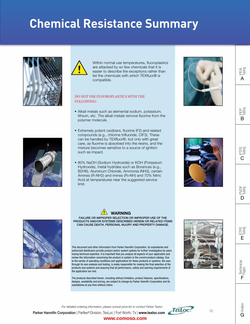
All of the tubing in this catalog features a low coefficient of friction and anti-stick properties, high temperature capabilities and the most corrosion and chemical resis-tance of all polymers. Within normal use temperatures, fluoropolymers are attacked by so few chemicals that it is easier to describe the exceptions rather than list the chemicals they are compatible with (see Chemical Resistance Summary, pg. F04). In addition, these chemically inert tubes are non-wetting and non-leaching making them ideal for a wide range of fluid and material handling applications.
Parker TexLoc fluoropolymer tubing is available in PTFE, FEP, PFA, High Purity PFA (H.P. PFA), ETFE and PVDF with some materials operating at temperatures up to 500°F/260°C. Each material has specific dominant characteristics, but all operate in high-temperature, corrosive environments.
Each catalog product page outlines Features, Certifica-tions, Typical Applications and the Dimensional Data for each product. In addition, the following icons are used for quickly identifying typical markets. For markets not listed, contact Customer Service.
Parker Hannifin Corporation | Parflex® Division, TexLoc | Fort Worth, Tx | www.texloc.com
For detailed ordering information, please consult price list or contact Parker Texloc.
3
All fluoropolymer tubing dimensions are continuosly monitored to ensure an overall quality product. Most tubing sizes are packaged in convenient 25-ft., 50-ft., 100-ft. and 1,000-ft. lengths. Custom lengths are available upon request.
Transportation Electrical Military Semiconductor
Industrial Pneumatic
Industrial Hydraulics
Fluid Handling
Life Science
Food & Beverage
Icon Identification
Tubing Pressure Ranges
Tubing pressures are calculated at 73˚F (23°C) and vary by material, tubing size and wallthickness. Please contact Customer Servicefor specific pressures.
www.comoso.com
Intro
PFA
Tu
bing
A
FEP
Tu
bing
B
PVD
F
Tubi
ng
D
PTFE
Tu
bing
C
Index
G
Tech
nica
l Pa
ges
F
ETFE
Tu
bing
E
Material Feature Overview
High Purity PFA pg. A02
� H.P. PFA (High Purity Perfluoroalkoxy) has the highest molecular weight available.
� Withstands corrosive surfactants for longer periods of time than standard products.
� Lowest level of extractables.
PFA pg. A04
� PFA (Perfluoroalkoxy) - When temperature and clarity are both factors, PFA is the resin of choice, offering the high-temperature attributes of PTFE, long continuous lengths, and almost as much clarity as FEP.
� High purity resins available.
� Low permeability.
Fully Conductive and Conductive I.D. tubing in PTFE and PFA Full Conductive are available
FEP pg. B02
� FEP (Fluorinated Ethylene Propylene) offers the highest clarity in the fluoropolymer market and is a close second to PTFE in chemical resistance.
� FEP is available in long, continuous lengths (1,000 feet and longer) , unlike PTFE, where the lengths range from 200 to 1,000 feet depending on size and wall thickness.
PTFE pg. C02
� PTFE (Polytetrafluorethylene) has the lowest coefficient of friction of any material known to man.
� PTFE tubing features unmatched chemical resistance and a non-stick surface that facilitates flow and eliminates media buildup.
PVDF pg. D02
� PVDF (Polyvinylidene Fluoride) offers a combination of properties beneficial for use in many critical applications requiring chemical resistance with low permeability.
� PVDF exhibits low extractable levels while providing high mechanical strength and abrasion resistance.
ETFE pg. E02
� ETFE (Ethylene Tetrafluoroethylene) has the best abrasion resistance in the fluoropolymer family.
Parker Hannifin Corporation | Parflex® Division, TexLoc | Fort Worth, Tx | www.texloc.com
For detailed ordering information, please consult price list or contact Parker Texloc.
4
www.comoso.com
FLAT SIZE – 8.5" X 11" (11 x 17 spreads to be separated during final gather)CUT SIZE – 8.5" X 11"BLEED SIZE – 8.75” X 11.25”FINISHINGS – Drill holes
Intro
PFA
Tu
bing
A
FEP
Tu
bing
B
PVD
F
Tubi
ng
D
PTFE
Tu
bing
C
Index
G
Tech
nica
l Pa
ges
F
ETFE
Tu
bing
E
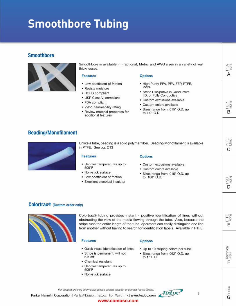
Smoothbore is available in Fractional, Metric and AWG sizes in a variety of wall thicknesses.
Smoothbore
Features
� Low coefficient of friction � Resists moisture � ROHS compliant � USP Class VI compliant � FDA compliant � VW-1 flammability rating � Review material properties for additional features
Unlike a tube, beading is a solid polymer fiber. Beading/Monofilament is available in PTFE. See pg. C13
Beading/Monofilament
Features
� Handles temperatures up to 500°F
� Non-stick surface � Low coefficient of friction � Excellent electrical insulator
Options
� Custom extrusions available � Custom colors available � Sizes range from .015" O.D. up to .188" O.D.
Options
� High Purity PFA, PFA, FEP, PTFE, PVDF
� Static Dissipative in Conductive I.D. or Fully Conductive
� Custom extrusions available � Custom colors available � Sizes range from .015" O.D. up to 4.0" O.D.
Colortrax® tubing provides instant - positive identification of lines without obstructing the view of the media flowing through the tube. Also, because the stripe runs the entire length of the tube, operators can easily distinguish one line from another without having to search for identification labels. Available in PTFE.
Colortrax® (Custom order only)
Features
� Quick visual identification of lines � Stripe is permanent, will not rub off
� Chemical resistant � Handles temperatures up to 500°F
� Non-stick surface
Options
� Up to 10 striping colors per tube � Sizes range from .062" O.D. up to 1" O.D.
Parker Hannifin Corporation | Parflex® Division, TexLoc | Fort Worth, Tx | www.texloc.com
For detailed ordering information, please consult price list or contact Parker Texloc.
5
Smoothbore Tubing
www.comoso.com
Intro
PFA
Tu
bing
A
FEP
Tu
bing
B
PVD
F
Tubi
ng
D
PTFE
Tu
bing
C
Index
G
Tech
nica
l Pa
ges
F
ETFE
Tu
bing
E
Options
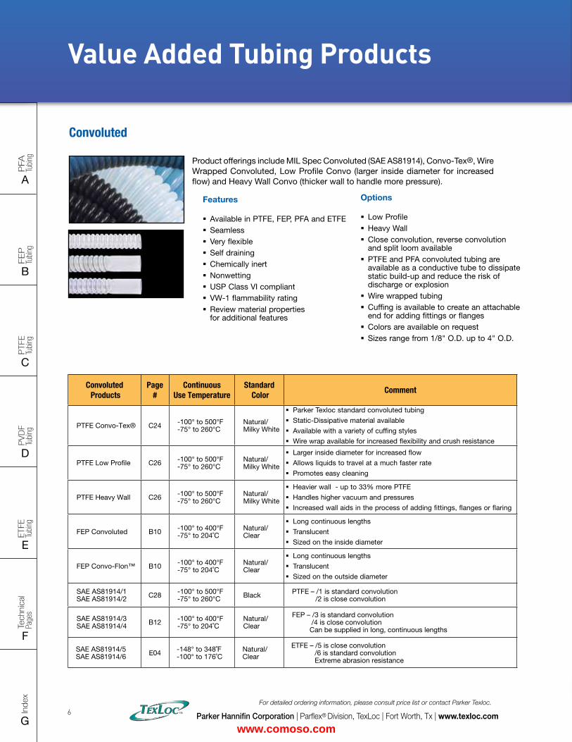
� Low Profile � Heavy Wall � Close convolution, reverse convolution and split loom available
� PTFE and PFA convoluted tubing are available as a conductive tube to dissipate static build-up and reduce the risk of discharge or explosion
� Wire wrapped tubing � Cuffing is available to create an attachable end for adding fittings or flanges
� Colors are available on request � Sizes range from 1/8" O.D. up to 4" O.D.
Convoluted
.
Features
� Available in PTFE, FEP, PFA and ETFE � Seamless � Very flexible � Self draining � Chemically inert � Nonwetting � USP Class VI compliant � VW-1 flammability rating � Review material properties for additional features
Product offerings include MIL Spec Convoluted (SAE AS81914), Convo-Tex®, Wire Wrapped Convoluted, Low Profile Convo (larger inside diameter for increased flow) and Heavy Wall Convo (thicker wall to handle more pressure).
Parker Hannifin Corporation | Parflex® Division, TexLoc | Fort Worth, Tx | www.texloc.com
For detailed ordering information, please consult price list or contact Parker Texloc.
6
Value Added Tubing Products
Convoluted Products
Page #
Continuous Use Temperature
Standard Color
Comment
PTFE Convo-Tex® C24 -100° to 500°F -75° to 260°C
Natural/ Milky White
� Parker Texloc standard convoluted tubing
� Static-Dissipative material available
� Available with a variety of cuffing styles
� Wire wrap available for increased flexibility and crush resistance
PTFE Low Profile C26 -100° to 500°F -75° to 260°C
Natural/ Milky White
� Larger inside diameter for increased flow
� Allows liquids to travel at a much faster rate
� Promotes easy cleaning
PTFE Heavy Wall C26 -100° to 500°F -75° to 260°C
Natural/ Milky White
� Heavier wall - up to 33% more PTFE
� Handles higher vacuum and pressures
� Increased wall aids in the process of adding fittings, flanges or flaring
FEP Convoluted B10 -100° to 400°F -75° to 204˚C
Natural/ Clear
� Long continuous lengths
� Translucent
� Sized on the inside diameter
FEP Convo-Flon™ B10 -100° to 400°F -75° to 204˚C
Natural/ Clear
� Long continuous lengths
� Translucent
� Sized on the outside diameter
SAE AS81914/1 SAE AS81914/2 C28 -100° to 500°F
-75° to 260°C Black PTFE – /1 is standard convolution /2 is close convolution
SAE AS81914/3SAE AS81914/4 B12 -100° to 400°F
-75° to 204˚CNatural/ Clear
FEP – /3 is standard convolution /4 is close convolution Can be supplied in long, continuous lengths
SAE AS81914/5SAE AS81914/6 E04 -148° to 348˚F
-100° to 176˚CNatural/ Clear
ETFE – /5 is close convolution /6 is standard convolution Extreme abrasion resistance
www.comoso.com
FLAT SIZE – 8.5" X 11" (11 x 17 spreads to be separated during final gather)CUT SIZE – 8.5" X 11"BLEED SIZE – 8.75” X 11.25”FINISHINGS – Drill holes
Intro
PFA
Tu
bing
A
FEP
Tu
bing
B
PVD
F
Tubi
ng
D
PTFE
Tu
bing
C
Index
G
Tech
nica
l Pa
ges
F
ETFE
Tu
bing
E
Value Added Tubing Products
Parker Hannifin Corporation | Parflex® Division, TexLoc | Fort Worth, Tx | www.texloc.com
For detailed ordering information, please consult price list or contact Parker Texloc.
9
Options
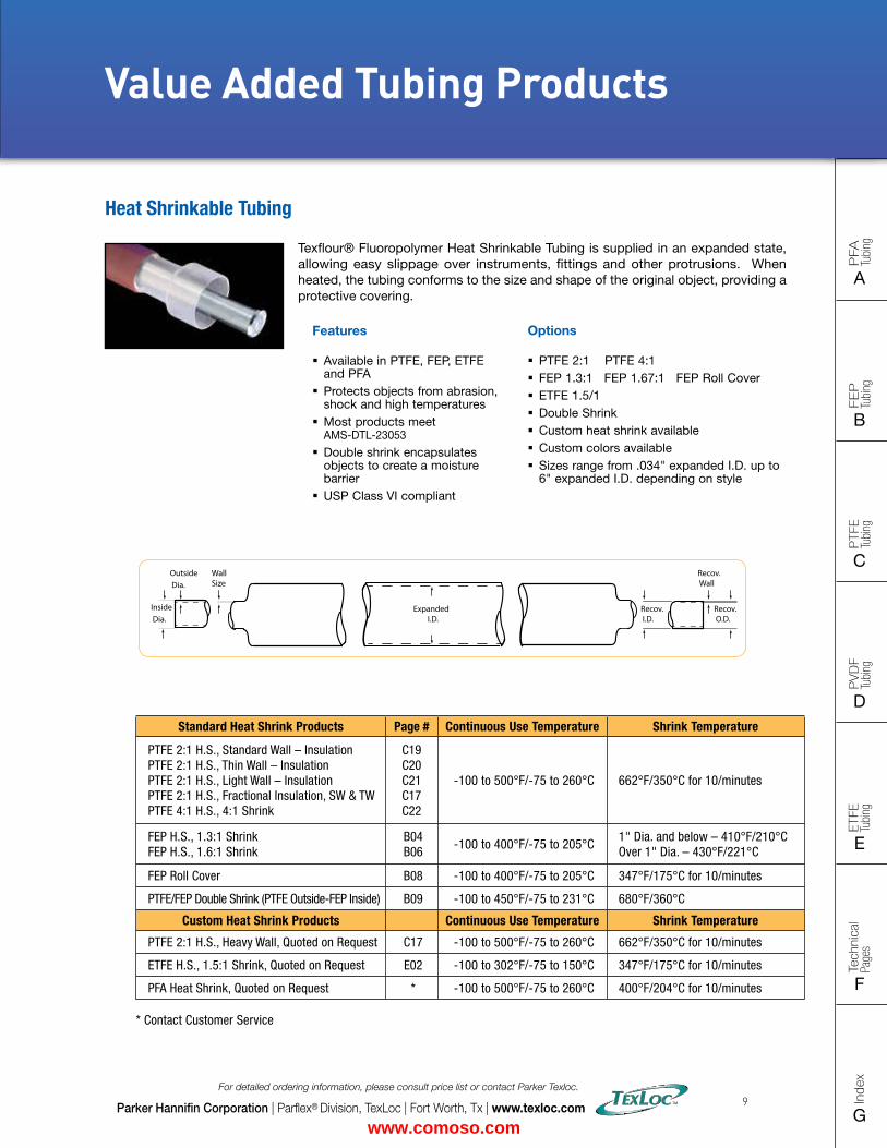
� PTFE 2:1 PTFE 4:1 � FEP 1.3:1 FEP 1.67:1 FEP Roll Cover � ETFE 1.5/1 � Double Shrink � Custom heat shrink available � Custom colors available � Sizes range from .034" expanded I.D. up to 6" expanded I.D. depending on style
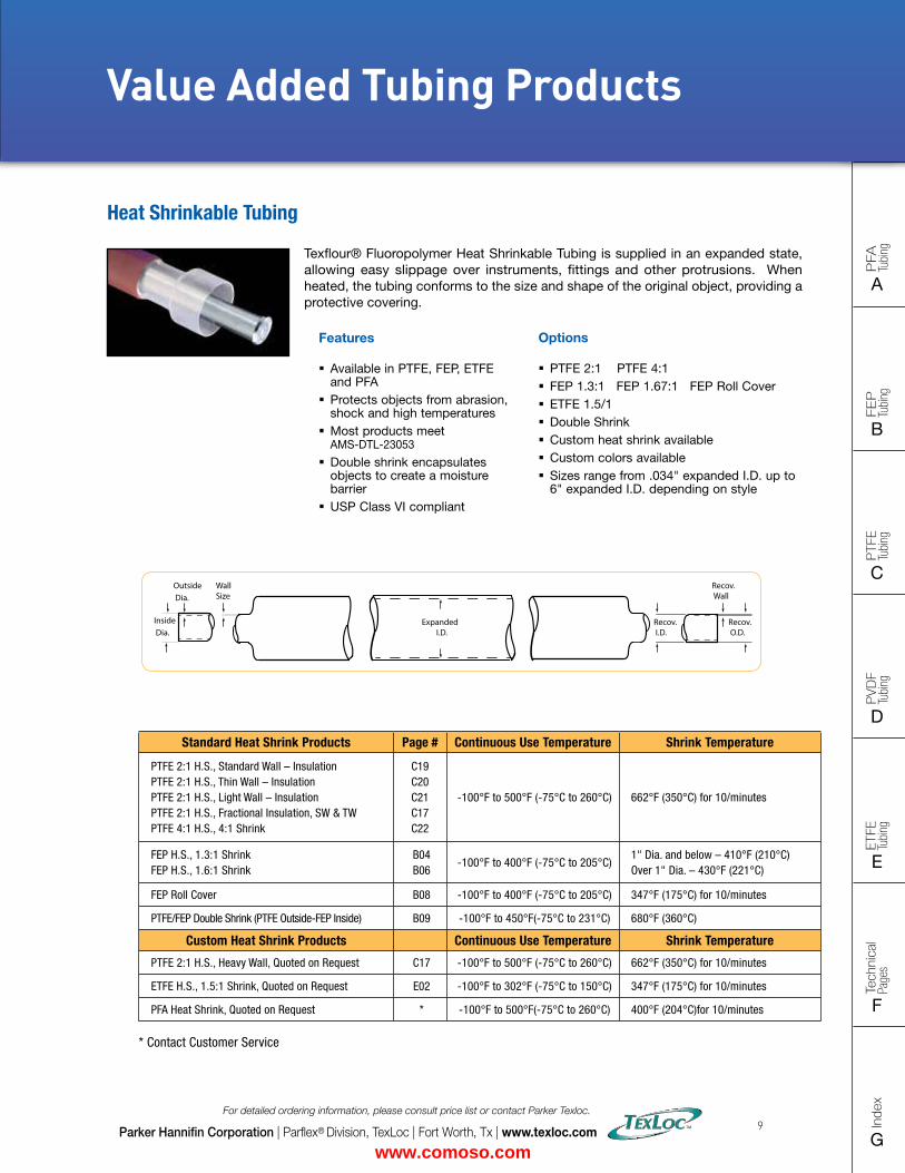
Texflour® Fluoropolymer Heat Shrinkable Tubing is supplied in an expanded state, allowing easy slippage over instruments, fittings and other protrusions. When heated, the tubing conforms to the size and shape of the original object, providing a protective covering.
Heat Shrinkable Tubing
Features
� Available in PTFE, FEP, ETFE and PFA
� Protects objects from abrasion, shock and high temperatures
� Most products meet AMS-DTL-23053
� Double shrink encapsulates objects to create a moisture barrier
� USP Class VI compliant
Standard Heat Shrink Products Page # Continuous Use Temperature Shrink Temperature
PTFE 2:1 H.S., Standard Wall – Insulation PTFE 2:1 H.S., Thin Wall – Insulation PTFE 2:1 H.S., Light Wall – Insulation PTFE 2:1 H.S., Fractional Insulation, SW & TW PTFE 4:1 H.S., 4:1 Shrink
C19 C20 C21 C17 C22
-100°F to 500°F (-75°C to 260°C) 662°F (350°C) for 10/minutes
FEP H.S., 1.3:1 Shrink FEP H.S., 1.6:1 Shrink
B04 B06
-100°F to 400°F (-75°C to 205°C)1" Dia. and below – 410°F (210°C) Over 1" Dia. – 430°F (221°C)
FEP Roll Cover B08 -100°F to 400°F (-75°C to 205°C) 347°F (175°C) for 10/minutes
PTFE/FEP Double Shrink (PTFE Outside-FEP Inside) B09 -100°F to 450°F(-75°C to 231°C) 680°F (360°C)
Custom Heat Shrink Products Continuous Use Temperature Shrink Temperature
PTFE 2:1 H.S., Heavy Wall, Quoted on Request C17 -100°F to 500°F (-75°C to 260°C) 662°F (350°C) for 10/minutes
ETFE H.S., 1.5:1 Shrink, Quoted on Request E02 -100°F to 302°F (-75°C to 150°C) 347°F (175°C) for 10/minutes
PFA Heat Shrink, Quoted on Request * -100°F to 500°F(-75°C to 260°C) 400°F (204°C)for 10/minutes
* Contact Customer Service
Recov. Wall
Recov. O.D.
Outside Dia.
Inside Dia.
WallSize
Recov. I.D.
Expanded I.D.
www.comoso.com
Intro
PFA
Tu
bing
A
FEP
Tu
bing
B
PVD
F
Tubi
ng
D
PTFE
Tu
bing
C
Index
G
Tech
nica
l Pa
ges
F
ETFE
Tu
bing
E
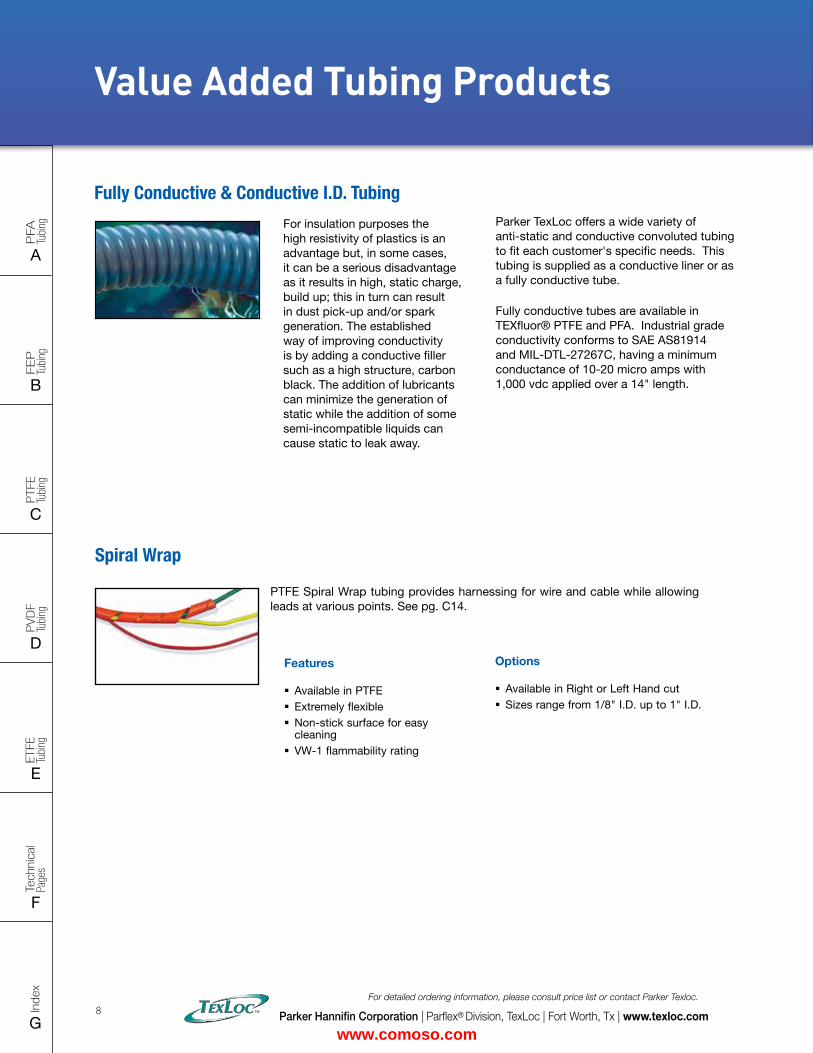
PTFE Spiral Wrap tubing provides harnessing for wire and cable while allowing leads at various points. See pg. C14.
Spiral Wrap
Features
� Available in PTFE � Extremely flexible � Non-stick surface for easy cleaning
� VW-1 flammability rating
Options
� Available in Right or Left Hand cut � Sizes range from 1/8" I.D. up to 1" I.D.
Parker Hannifin Corporation | Parflex® Division, TexLoc | Fort Worth, Tx | www.texloc.com
For detailed ordering information, please consult price list or contact Parker Texloc.
8
Value Added Tubing Products
Fully Conductive & Conductive I.D. Tubing
For insulation purposes the high resistivity of plastics is an advantage but, in some cases, it can be a serious disadvantage as it results in high, static charge, build up; this in turn can result in dust pick-up and/or spark generation. The established way of improving conductivity is by adding a conductive filler such as a high structure, carbon black. The addition of lubricants can minimize the generation of static while the addition of some semi-incompatible liquids can cause static to leak away.
Parker TexLoc offers a wide variety of anti-static and conductive convoluted tubing to fit each customer's specific needs. This tubing is supplied as a conductive liner or as a fully conductive tube.
Fully conductive tubes are available in TEXfluor® PTFE and PFA. Industrial grade conductivity conforms to SAE AS81914 and MIL-DTL-27267C, having a minimum conductance of 10-20 micro amps with 1,000 vdc applied over a 14" length.
www.comoso.com
FLAT SIZE – 8.5" X 11" (11 x 17 spreads to be separated during final gather)CUT SIZE – 8.5" X 11"BLEED SIZE – 8.75” X 11.25”FINISHINGS – Drill holes
Intro
PFA
Tu
bing
A
FEP
Tu
bing
B
PVD
F
Tubi
ng
D
PTFE
Tu
bing
C
Index
G
Tech
nica
l Pa
ges
F
ETFE
Tu
bing
E
Value Added Tubing Products
Parker Hannifin Corporation | Parflex® Division, TexLoc | Fort Worth, Tx | www.texloc.com
For detailed ordering information, please consult price list or contact Parker Texloc.
9
Options
� PTFE 2:1 PTFE 4:1 � FEP 1.3:1 FEP 1.67:1 FEP Roll Cover � ETFE 1.5/1 � Double Shrink � Custom heat shrink available � Custom colors available � Sizes range from .034" expanded I.D. up to 6" expanded I.D. depending on style
Texflour® Fluoropolymer Heat Shrinkable Tubing is supplied in an expanded state, allowing easy slippage over instruments, fittings and other protrusions. When heated, the tubing conforms to the size and shape of the original object, providing a protective covering.
Heat Shrinkable Tubing
Features
� Available in PTFE, FEP, ETFE and PFA
� Protects objects from abrasion, shock and high temperatures
� Most products meet AMS-DTL-23053
� Double shrink encapsulates objects to create a moisture barrier
� USP Class VI compliant
Standard Heat Shrink Products Page # Continuous Use Temperature Shrink Temperature
PTFE 2:1 H.S., Standard Wall – Insulation PTFE 2:1 H.S., Thin Wall – Insulation PTFE 2:1 H.S., Light Wall – Insulation PTFE 2:1 H.S., Fractional Insulation, SW & TW PTFE 4:1 H.S., 4:1 Shrink
C19 C20 C21 C17 C22
-100 to 500°F/-75 to 260°C 662°F/350°C for 10/minutes
FEP H.S., 1.3:1 Shrink FEP H.S., 1.6:1 Shrink
B04 B06
-100 to 400°F/-75 to 205°C1" Dia. and below – 410°F/210°C Over 1" Dia. – 430°F/221°C
FEP Roll Cover B08 -100 to 400°F/-75 to 205°C 347°F/175°C for 10/minutes
PTFE/FEP Double Shrink (PTFE Outside-FEP Inside) B09 -100 to 450°F/-75 to 231°C 680°F/360°C
Custom Heat Shrink Products Continuous Use Temperature Shrink Temperature
PTFE 2:1 H.S., Heavy Wall, Quoted on Request C17 -100 to 500°F/-75 to 260°C 662°F/350°C for 10/minutes
ETFE H.S., 1.5:1 Shrink, Quoted on Request E02 -100 to 302°F/-75 to 150°C 347°F/175°C for 10/minutes
PFA Heat Shrink, Quoted on Request * -100 to 500°F/-75 to 260°C 400°F/204°C for 10/minutes * Contact Customer Service
Recov. Wall
Recov. O.D.
Outside Dia.
Inside Dia.
WallSize
Recov. I.D.
Expanded I.D.
www.comoso.com
Intro
PFA
Tu
bing
A
FEP
Tu
bing
B
PVD
F
Tubi
ng
D
PTFE
Tu
bing
C
Index
G
Tech
nica
l Pa
ges
F
ETFE
Tu
bing
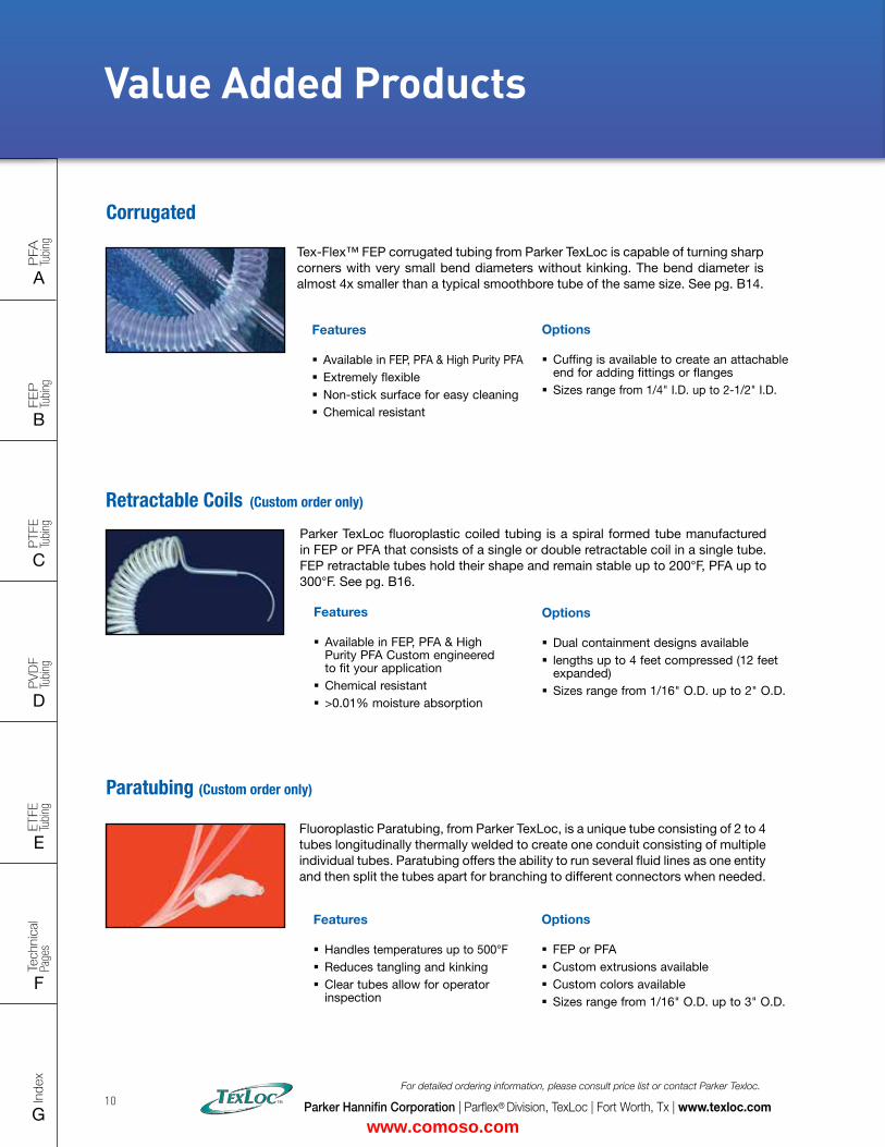
EFluoroplastic Paratubing, from Parker TexLoc, is a unique tube consisting of 2 to 4 tubes longitudinally thermally welded to create one conduit consisting of multiple individual tubes. Paratubing offers the ability to run several fluid lines as one entity and then split the tubes apart for branching to different connectors when needed.
Paratubing (Custom order only)
Features
� Handles temperatures up to 500°F � Reduces tangling and kinking � Clear tubes allow for operator inspection
Options
� FEP or PFA � Custom extrusions available � Custom colors available � Sizes range from 1/16" O.D. up to 3" O.D.
Parker TexLoc fluoroplastic coiled tubing is a spiral formed tube manufactured in FEP or PFA that consists of a single or double retractable coil in a single tube. FEP retractable tubes hold their shape and remain stable up to 200°F, PFA up to 300°F. See pg. B16.
Retractable Coils (Custom order only)
Features
� Available in FEP, PFA & High Purity PFA Custom engineered to fit your application
� Chemical resistant � >0.01% moisture absorption
Options
� Dual containment designs available � lengths up to 4 feet compressed (12 feet expanded)
� Sizes range from 1/16" O.D. up to 2" O.D.
Value Added Products
Tex-Flex™ FEP corrugated tubing from Parker TexLoc is capable of turning sharp corners with very small bend diameters without kinking. The bend diameter is almost 4x smaller than a typical smoothbore tube of the same size. See pg. B14.
Corrugated
Features
� Available in FEP, PFA & High Purity PFA � Extremely flexible � Non-stick surface for easy cleaning � Chemical resistant
Options
� Cuffing is available to create an attachable end for adding fittings or flanges
� Sizes range from 1/4" I.D. up to 2-1/2" I.D.
Parker Hannifin Corporation | Parflex® Division, TexLoc | Fort Worth, Tx | www.texloc.com
For detailed ordering information, please consult price list or contact Parker Texloc.
10
www.comoso.com
FLAT SIZE – 8.5" X 11" (11 x 17 spreads to be separated during final gather)CUT SIZE – 8.5" X 11"BLEED SIZE – 8.75” X 11.25”FINISHINGS – Drill holes
Intro
PFA
Tu
bing
A
FEP
Tu
bing
B
PVD
F
Tubi
ng
D
PTFE
Tu
bing
C
Index
G
Tech
nica
l Pa
ges
F
ETFE
Tu
bing
E
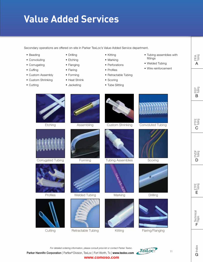
� Beading
� Convoluting
� Corrugating
� Cuffing
� Custom Assembly
� Custom Shrinking
� Cutting
� Drilling
� Etching
� Flanging
� Flaring
� Forming
� Heat Shrink
� Jacketing
� Kitting
� Marking
� Perforations
� Profiles
� Retractable Tubing
� Scoring
� Tube Slitting
� Tubing assemblies with fittings
� Welded Tubing
� Wire reinforcement
Secondary operations are offered on-site in Parker TexLoc’s Value-Added Service department.
Convoluted TubingAssembling
Tubing Assemblies ScoringCorrugated Tubing Forming
Marking Drilling
Kitting Flaring/FlangingCutting Retractable Tubing
Welded Tubing
Etching Custom Shrinking
Value Added Services
Profiles
Parker Hannifin Corporation | Parflex® Division, TexLoc | Fort Worth, Tx | www.texloc.com
For detailed ordering information, please consult price list or contact Parker Texloc.
11
www.comoso.com
Intro
PFA
Tu
bing
A
FEP
Tu
bing
B
PVD
F
Tubi
ng
D
PTFE
Tu
bing
C
Index
G
Tech
nica
l Pa
ges
F
ETFE
Tu
bing
E
Applications
Parker Hannifin Corporation | Parflex® Division, TexLoc | Fort Worth, Tx | www.texloc.com
For detailed ordering information, please consult price list or contact Parker Texloc.
12
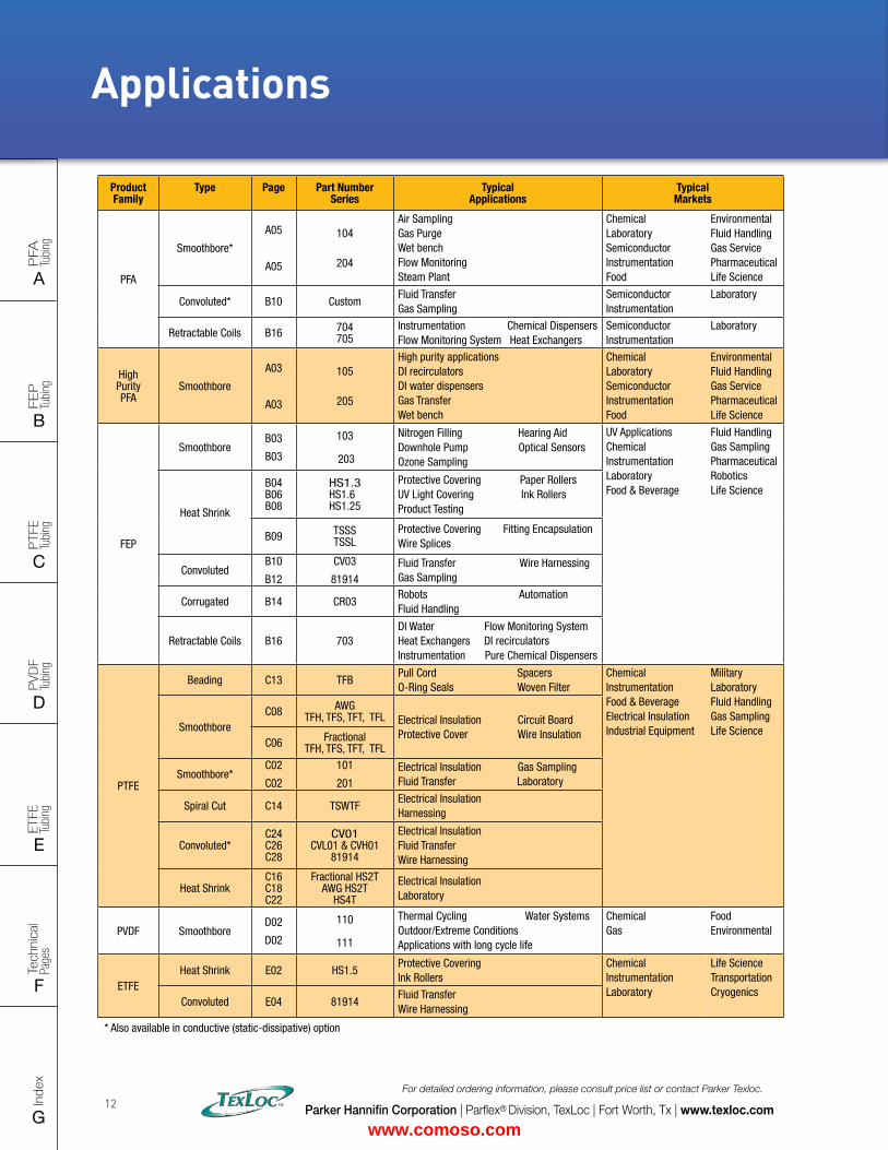
Product Family
Type Page Part Number Series
Typical Applications
Typical Markets
PFA
Smoothbore*
A05
A05
104
204
Air Sampling Gas Purge Wet bench Flow Monitoring Steam Plant
Chemical Laboratory Semiconductor Instrumentation Food
Environmental Fluid Handling Gas Service Pharmaceutical Life Science
Convoluted* B10 CustomFluid Transfer Gas Sampling
Semiconductor Instrumentation
Laboratory
Retractable Coils B16 704 705
Instrumentation Chemical Dispensers Flow Monitoring System Heat Exchangers
Semiconductor Instrumentation
Laboratory
High Purity PFA
Smoothbore
A03
A03
105
205
High purity applications DI recirculators DI water dispensers Gas Transfer Wet bench
Chemical Laboratory Semiconductor Instrumentation Food
Environmental Fluid Handling Gas Service Pharmaceutical Life Science
FEP
Smoothbore B03
B03
103
203
Nitrogen Filling Hearing Aid Downhole Pump Optical Sensors Ozone Sampling
UV Applications Chemical Instrumentation Laboratory Food & Beverage
Fluid Handling Gas Sampling Pharmaceutical Robotics Life Science
Heat Shrink
B04 B06 B08
HS1.3 HS1.60 HS1.25
Protective Covering Paper Rollers UV Light Covering Ink Rollers Product Testing
B09 TSSS TSSL
Protective Covering Fitting Encapsulation Wire Splices
ConvolutedB10
B12
CV03
81914Fluid Transfer Wire Harnessing Gas Sampling
Corrugated B14 CR03Robots Automation Fluid Handling
Retractable Coils B16 703DI Water Flow Monitoring System Heat Exchangers DI recirculators Instrumentation Pure Chemical Dispensers
PTFE
Beading C13 TFBPull Cord Spacers O-Ring Seals Woven Filter
Chemical Instrumentation Food & Beverage Electrical Insulation Industrial Equipment
Military Laboratory Fluid Handling Gas Sampling Life ScienceSmoothbore
C08 AWG TFH, TFS, TFT, TFL Electrical Insulation Circuit Board
Protective Cover Wire InsulationC06 Fractional
TFH, TFS, TFT, TFL
Smoothbore*C02
C02
101
201Electrical Insulation Gas Sampling Fluid Transfer Laboratory
Spiral Cut C14 TSWTF Electrical Insulation Harnessing
Convoluted*C24 C26 C28
CV01 CVL01 & CVH01
81914
Electrical Insulation Fluid Transfer Wire Harnessing
Heat ShrinkC16 C18 C22
Fractional HS2T AWG HS2T
HS4T
Electrical Insulation Laboratory
PVDF SmoothboreD02
D02
110 111
Thermal Cycling Water Systems Outdoor/Extreme Conditions Applications with long cycle life
Chemical Gas
Food Environmental
ETFEHeat Shrink E02 HS1.5
Protective Covering Ink Rollers
Chemical Instrumentation Laboratory
Life Science Transportation Cryogenics
Convoluted E04 81914Fluid Transfer Wire Harnessing
* Also available in conductive (static-dissipative) option
www.comoso.com
FLAT SIZE – 8.5" X 11" (11 x 17 spreads to be separated during final gather)CUT SIZE – 8.5" X 11"BLEED SIZE – 8.75” X 11.25”FINISHINGS – Drill holes
Intro
PFA
Tu
bing
A
FEP
Tu
bing
B
PVD
F
Tubi
ng
D
PTFE
Tu
bing
C
Index
G
Tech
nica
l Pa
ges
F
ETFE
Tu
bing
E
This document and other information from Parker Hannifin Corporation, its subsidiaries and authorized distributors provide product and/or system options for further investigation by users having technical expertise. It is important that you analyze all aspects of your application and review the information concerning the product or system in the current product catalog. Due to the variety of operating conditions and applications for these products or systems, the user, through its own analysis and testing, is solely responsible for making the final selection of the products and systems and assuring that all performance, safety and warning requirements of the application are met.
The products described herein, including without limitation, product features, specifications, designs, availability and pricing, are subject to change by Parker Hannifin Corporation and its subsidiaries at any time without notice.
FAILURE OR IMPROPER SELECTION OR IMPROPER USE OF THE PRODUCTS AND/OR SYSTEMS DESCRIBED HEREIN OR RELATED ITEMS
CAN CAUSE DEATH, PERSONAL INJURY AND PROPERTY DAMAGE.
DO NOT USE FLUOROPLASTICS WITH THE FOLLOWING:
� Alkali metals such as elemental sodium, potassium, lithium, etc. The alkali metals remove fluorine from the polymer molecule.
� Extremely potent oxidizers, fluorine (F2) and related compounds (e.g., chlorine trifluoride, CIF3). These can be handled by TEXfluor®, but only with great care, as fluorine is absorbed into the resins, and the mixture becomes sensitive to a source of ignition such as impact.
� 80% NaOH (Sodium Hydroxide) or KOH (Potassium Hydroxide), metal hydrides such as Borances (e.g., B2H6), Aluminum Chloride, Ammonia (NH3), certain Amines (R-NH2) and imines (R=NH) and 70% Nitric Acid at temperatures near the suggested service limit.
Within normal use temperatures, fluoroplastics are attacked by so few chemicals that it is easier to describe the exceptions rather than list the chemicals with which TEXfluor® is compatible.
WARNING
Parker Hannifin Corporation | Parflex® Division, TexLoc | Fort Worth, Tx | www.texloc.com
For detailed ordering information, please consult price list or contact Parker Texloc.
13
Chemical Resistance Summary
www.comoso.com
Intro
PFA
Tu
bing
A
FEP
Tu
bing
B
PVD
F
Tubi
ng
D
PTFE
Tu
bing
C
Index
G
Tech
nica
l Pa
ges
F
ETFE
Tu
bing
E
Parker Hannifin Corporation | Parflex® Division, TexLoc | Fort Worth, Tx | www.texloc.com
For detailed ordering information, please consult price list or contact Parker Texloc.
14
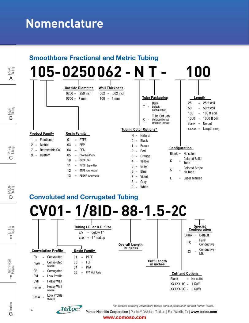
Nomenclature
105-
1 = Fractional2 = Metric7 = Retractable Coil9 = Custom
Product Family
01 = PTFE03 = FEP04 = PFA05 = PFA High Purity
10 = PVDF: Flex
11 = PVDF: Super-Flex
12 = ETFE NONSTANDARD
13 = PEEK® NONSTANDARD
Resin Family
062 - N T - 100
N = Natural0 = Black1 = Brown2 = Red3 = Orange4 = Yellow5 = Green6 = Blue7 = Violet8 = Gray9 = White
Tubing Color Options*
T =Bulk Default Configuration
C =Tube Cut Job (followed by cut length in inches)
Tube Packaging
0250
25 = 25 ft coil50 = 50 ft coil100 = 100 ft coil1000 = 1000 ft coilBlank = No cutxx.xxx = Length (inch)
Length
Blank = No color
C = Colored Solid Tube
S = Colored Stripe on Tube
L = Laser Marked
Configuration
0250 = .250 inch 0700 = 7 mm
Outside Diameter062 = .062 inch100 = 1 mm
Wall Thickness
Smoothbore Fractional and Metric Tubing
Convoluted and Corrugated Tubing
01-
01 = PTFE03 = FEP04 = PFA05 = PFA High Purity
Resin Family
CV 88-1.5-2C
Convolution Profile
CV = Convoluted
CVW = Convoluted w/wire
CR = CorrugatedCVL = Low ProfileCVH = Heavy Wall
CVHW = Heavy Wall w/wire
CVLW = Low Profile W/wire
1/8ID-
Blank = No cuffsXX.XXX-1C = 1 CuffXX.XXX-2C = 2 Cuffs
Cuff and Options
Blank = Default
FC = Fully Conductive
CI = Conductive I.D.
Special Configuration
x/x = below 1"x.xx = 1" and up
Tubing I.D. or O.D. Size
Overall Length in inches
Cuff Length in inches
www.comoso.com
FLAT SIZE – 8.5" X 11" (11 x 17 spreads to be separated during final gather)CUT SIZE – 8.5" X 11"BLEED SIZE – 8.75” X 11.25”FINISHINGS – Drill holes
Intro
PFA
Tu
bing
A
FEP
Tu
bing
B
PVD
F
Tubi
ng
D
PTFE
Tu
bing
C
Index
G
Tech
nica
l Pa
ges
F
ETFE
Tu
bing
E
Parker Hannifin Corporation | Parflex® Division, TexLoc | Fort Worth, Tx | www.texloc.com
For detailed ordering information, please consult price list or contact Parker Texloc.
15
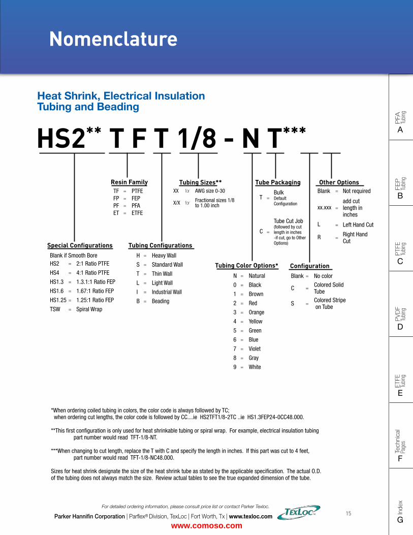
Nomenclature
T =Bulk Default Configuration
C =
Tube Cut Job (followed by cut length in inches -if cut, go to Other Options)
HS2**
Blank if Smooth BoreHS2 = 2:1 Ratio PTFE
HS4 = 4:1 Ratio PTFE
HS1.3 = 1.3.1:1 Ratio FEP
HS1.6 = 1.67:1 Ratio FEP
HS1.25 = 1.25:1 Ratio FEP
TSW = Spiral Wrap
Special Configurations
H = Heavy Wall
S = Standard Wall
T = Thin Wall
L = Light Wall
I = Industrial Wall
B = Beading
Tubing Configurations
1/8 - N T***
N = Natural
0 = Black
1 = Brown
2 = Red
3 = Orange
4 = Yellow
5 = Green
6 = Blue
7 = Violet
8 = Gray
9 = White
Tubing Color Options*
XX for AWG size 0-30
X/X for Fractional sizes 1/8 to 1.00 inch
Tubing Sizes** Tube Packaging
Blank = No color
C = Colored Solid Tube
S = Colored Stripe on Tube
Configuration
Blank = Not required
xx.xxx =add cut length in inches
L = Left Hand Cut
R = Right Hand Cut
Other Options
T F TResin FamilyTF = PTFEFP = FEPPF = PFAET = ETFE
Heat Shrink, Electrical Insulation Tubing and Beading
*When ordering coiled tubing in colors, the color code is always followed by TC; when ordering cut lengths, the color code is followed by CC....ie HS2TFT1/8-2TC ..ie HS1.3FEP24-0CC48.000.
**This first configuration is only used for heat shrinkable tubing or spiral wrap. For example, electrical insulation tubing part number would read TFT-1/8-NT.
***When changing to cut length, replace the T with C and specify the length in inches. If this part was cut to 4 feet, part number would read TFT-1/8-NC48.000.
Sizes for heat shrink designate the size of the heat shrink tube as stated by the applicable specification. The actual O.D. of the tubing does not always match the size. Review actual tables to see the true expanded dimension of the tube.
www.comoso.com
Intro
PFA
Tu
bing
A
FEP
Tu
bing
B
PVD
F
Tubi
ng
D
PTFE
Tu
bing
C
Index
G
Tech
nica
l Pa
ges
F
ETFE
Tu
bing
E
Parker Hannifin Corporation | Parflex® Division, TexLoc | Fort Worth, Tx | www.texloc.com
For detailed ordering information, please consult price list or contact Parker Texloc.
16
Bend Radius Curve Fluoropolymer TubingNotes
www.comoso.com

FLAT SIZE – 8.5" X 11" (11 x 17 spreads to be separated during final gather)CUT SIZE – 8.5" X 11"BLEED SIZE – 8.75” X 11.25”FINISHINGS – Drill holes
Intro
PFA
Tu
bing
A
FEP
Tu
bing
B
PVD
F
Tubi
ng
D
PTFE
Tu
bing
C
Index
G
Tech
nica
l Pa
ges
F
ETFE
Tu
bing
E
FEP PFA PTFE
=Fluoroplastics /Fluoropolymers
LDPE HDPEPP/PAPMP
= Low Density Polyethylene = High Density Polyethylene = Polypropylene/Polyallomer = Polymethylpentene
PC PVDC PSF
= Polycarbonate = Polyvinylchloride = Polysulfone
PFA PRODUCTS
PFA (Perfluoroalkoxy)Working Temperature: 500°F (260°C) Color: Clear with light blue or tint
• High purity resins available• Low permeation resins available• Use when you need the temperature
range of PTFE and the clarity of FEP• Exceptional heat resistance• Self extinguishing• Nonwetting• Good flexlife
High Purity PFA (Perfluoroalkoxy)Working Temperature: 500°F (260°C) Color: Clear with light blue or tint See characteristics of PFA with these additional features:
• Lowest level of extractables• Highest molecular weight available• Withstands corrosive surfactants for
longer periods of time• Higher purity
High Purity PFA Fractional Industrial Wall Fractional Heavy Wall Metric
Standard PFA Industrial Wall Heavy Wall Metric Retractable Coils, Convoluted and Corrugated are
also available. Refer to FEP section.
www.comoso.com
Intro
PFA
Tu
bing
A
FEP
Tu
bing
B
PVD
F
Tubi
ng
D
PTFE
Tu
bing
C
Index
G
Tech
nica
l Pa
ges
F
ETFE
Tu
bing
E
Parker Hannifin Corporation | Parflex® Division, TexLoc | Fort Worth, Tx | www.texloc.com
For detailed ordering information, please consult price list or contact Parker Texloc.
A02
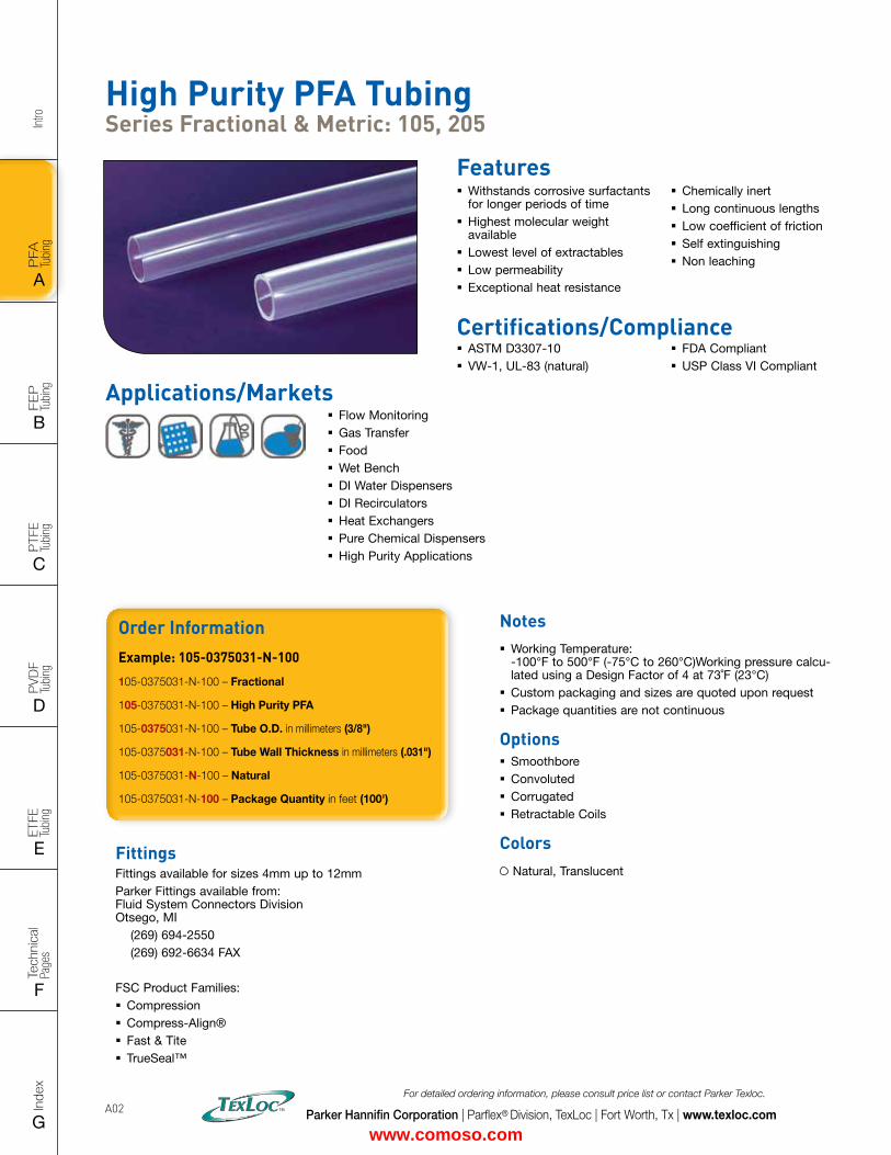
High Purity PFA Tubing Series Fractional & Metric: 105, 205
Features � Withstands corrosive surfactants for longer periods of time
� Highest molecular weight available
� Lowest level of extractables � Low permeability � Exceptional heat resistance
� Chemically inert � Long continuous lengths � Low coefficient of friction � Self extinguishing � Non leaching
Certifications/Compliance � ASTM D3307-10 � VW-1, UL-83 (natural)
� FDA Compliant � USP Class VI Compliant
FittingsFittings available for sizes 4mm up to 12mm Parker Fittings available from: Fluid System Connectors Division Otsego, MI (269) 694-2550 (269) 692-6634 FAX
FSC Product Families: � Compression � Compress-Align® � Fast & Tite � TrueSeal™
Order InformationExample: 105-0375031-N-100
105-0375031-N-100 – Fractional
105-0375031-N-100 – High Purity PFA
105-0375031-N-100 – Tube O.D. in millimeters (3/8")
105-0375031-N-100 – Tube Wall Thickness in millimeters (.031")
105-0375031-N-100 – Natural
105-0375031-N-100 – Package Quantity in feet (100')
Notes � Working Temperature: -100°F to 500°F (-75°C to 260°C)Working pressure calcu-lated using a Design Factor of 4 at 73˚F (23°C)
� Custom packaging and sizes are quoted upon request � Package quantities are not continuous
Options � Smoothbore � Convoluted � Corrugated � Retractable Coils
Colors Natural, Translucent
� Flow Monitoring � Gas Transfer � Food � Wet Bench � DI Water Dispensers � DI Recirculators � Heat Exchangers � Pure Chemical Dispensers � High Purity Applications
Applications/Markets
www.comoso.com
FLAT SIZE – 8.5" X 11" (11 x 17 spreads to be separated during final gather)CUT SIZE – 8.5" X 11"BLEED SIZE – 8.75” X 11.25”FINISHINGS – Drill holes
Intro
PFA
Tu
bing
A
FEP
Tu
bing
B
PVD
F
Tubi
ng
D
PTFE
Tu
bing
C
Index
G
Tech
nica
l Pa
ges
F
ETFE
Tu
bing
E
Parker Hannifin Corporation | Parflex® Division, TexLoc | Fort Worth, Tx | www.texloc.com
For detailed ordering information, please consult price list or contact Parker Texloc.
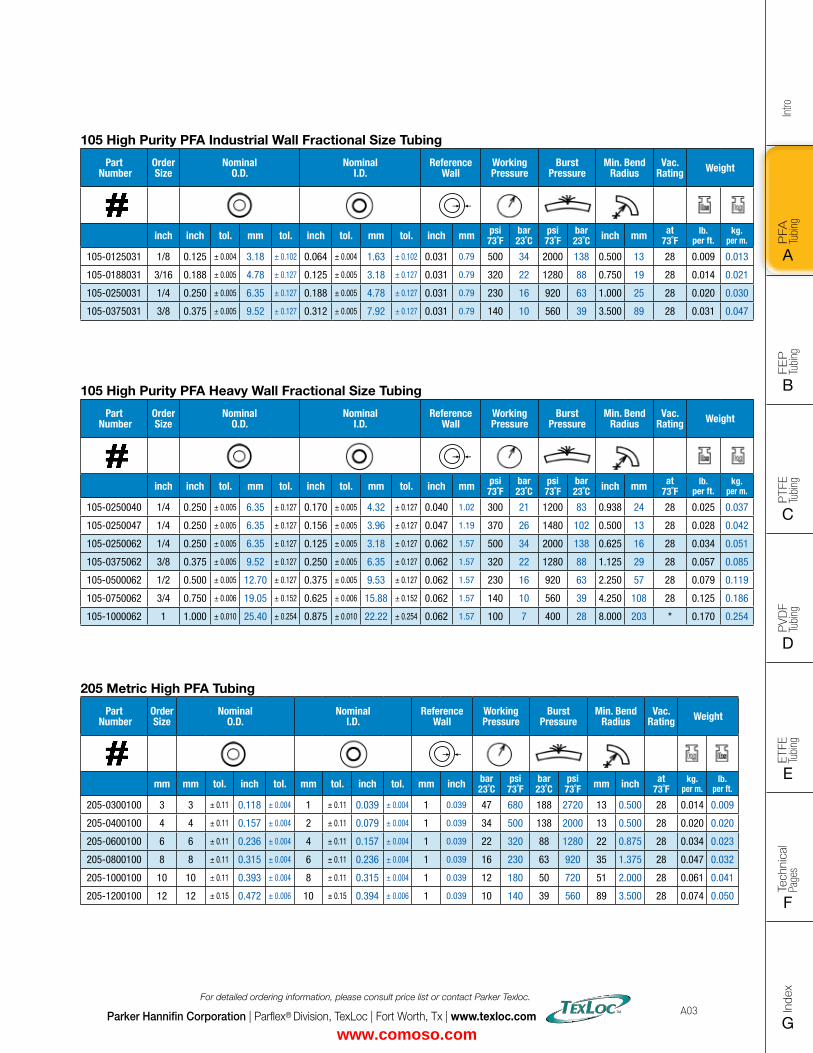
A03
205 Metric High PFA Tubing
Part Number
Order Size
Nominal O.D.
Nominal I.D.
Reference Wall
Working Pressure
Burst Pressure
Min. Bend Radius
Vac. Rating Weight
mm mm tol. inch tol. mm tol. inch tol. mm inch bar23˚C
psi73˚F
bar23˚C
psi73˚F mm inch at
73˚Fkg.
per m.lb.
per ft.
205-0300100 3 3 ± 0.11 0.118 ± 0.004 1 ± 0.11 0.039 ± 0.004 1 0.039 47 680 188 2720 13 0.500 28 0.014 0.009
205-0400100 4 4 ± 0.11 0.157 ± 0.004 2 ± 0.11 0.079 ± 0.004 1 0.039 34 500 138 2000 13 0.500 28 0.020 0.020
205-0600100 6 6 ± 0.11 0.236 ± 0.004 4 ± 0.11 0.157 ± 0.004 1 0.039 22 320 88 1280 22 0.875 28 0.034 0.023
205-0800100 8 8 ± 0.11 0.315 ± 0.004 6 ± 0.11 0.236 ± 0.004 1 0.039 16 230 63 920 35 1.375 28 0.047 0.032
205-1000100 10 10 ± 0.11 0.393 ± 0.004 8 ± 0.11 0.315 ± 0.004 1 0.039 12 180 50 720 51 2.000 28 0.061 0.041
205-1200100 12 12 ± 0.15 0.472 ± 0.006 10 ± 0.15 0.394 ± 0.006 1 0.039 10 140 39 560 89 3.500 28 0.074 0.050
105 High Purity PFA Industrial Wall Fractional Size Tubing
Part Number
Order Size
Nominal O.D.
Nominal I.D.
Reference Wall
Working Pressure
Burst Pressure
Min. Bend Radius
Vac. Rating Weight
inch inch tol. mm tol. inch tol. mm tol. inch mm psi73˚F
bar23˚C
psi73˚F
bar23˚C inch mm at
73˚Flb.
per ft.kg.
per m.
105-0125031 1/8 0.125 ± 0.004 3.18 ± 0.102 0.064 ± 0.004 1.63 ± 0.102 0.031 0.79 500 34 2000 138 0.500 13 28 0.009 0.013
105-0188031 3/16 0.188 ± 0.005 4.78 ± 0.127 0.125 ± 0.005 3.18 ± 0.127 0.031 0.79 320 22 1280 88 0.750 19 28 0.014 0.021
105-0250031 1/4 0.250 ± 0.005 6.35 ± 0.127 0.188 ± 0.005 4.78 ± 0.127 0.031 0.79 230 16 920 63 1.000 25 28 0.020 0.030
105-0375031 3/8 0.375 ± 0.005 9.52 ± 0.127 0.312 ± 0.005 7.92 ± 0.127 0.031 0.79 140 10 560 39 3.500 89 28 0.031 0.047
105 High Purity PFA Heavy Wall Fractional Size Tubing
Part Number
Order Size
Nominal O.D.
Nominal I.D.
Reference Wall
Working Pressure
Burst Pressure
Min. Bend Radius
Vac. Rating Weight
inch inch tol. mm tol. inch tol. mm tol. inch mm psi73˚F
bar23˚C
psi73˚F
bar23˚C inch mm at
73˚Flb.
per ft.kg.
per m.
105-0250040 1/4 0.250 ± 0.005 6.35 ± 0.127 0.170 ± 0.005 4.32 ± 0.127 0.040 1.02 300 21 1200 83 0.938 24 28 0.025 0.037
105-0250047 1/4 0.250 ± 0.005 6.35 ± 0.127 0.156 ± 0.005 3.96 ± 0.127 0.047 1.19 370 26 1480 102 0.500 13 28 0.028 0.042
105-0250062 1/4 0.250 ± 0.005 6.35 ± 0.127 0.125 ± 0.005 3.18 ± 0.127 0.062 1.57 500 34 2000 138 0.625 16 28 0.034 0.051
105-0375062 3/8 0.375 ± 0.005 9.52 ± 0.127 0.250 ± 0.005 6.35 ± 0.127 0.062 1.57 320 22 1280 88 1.125 29 28 0.057 0.085
105-0500062 1/2 0.500 ± 0.005 12.70 ± 0.127 0.375 ± 0.005 9.53 ± 0.127 0.062 1.57 230 16 920 63 2.250 57 28 0.079 0.119
105-0750062 3/4 0.750 ± 0.006 19.05 ± 0.152 0.625 ± 0.006 15.88 ± 0.152 0.062 1.57 140 10 560 39 4.250 108 28 0.125 0.186
105-1000062 1 1.000 ± 0.010 25.40 ± 0.254 0.875 ± 0.010 22.22 ± 0.254 0.062 1.57 100 7 400 28 8.000 203 * 0.170 0.254
www.comoso.com
Intro
PFA
Tu
bing
A
FEP
Tu
bing
B
PVD
F
Tubi
ng
D
PTFE
Tu
bing
C
Index
G
Tech
nica
l Pa
ges
F
ETFE
Tu
bing
E
Parker Hannifin Corporation | Parflex® Division, TexLoc | Fort Worth, Tx | www.texloc.com
For detailed ordering information, please consult price list or contact Parker Texloc.
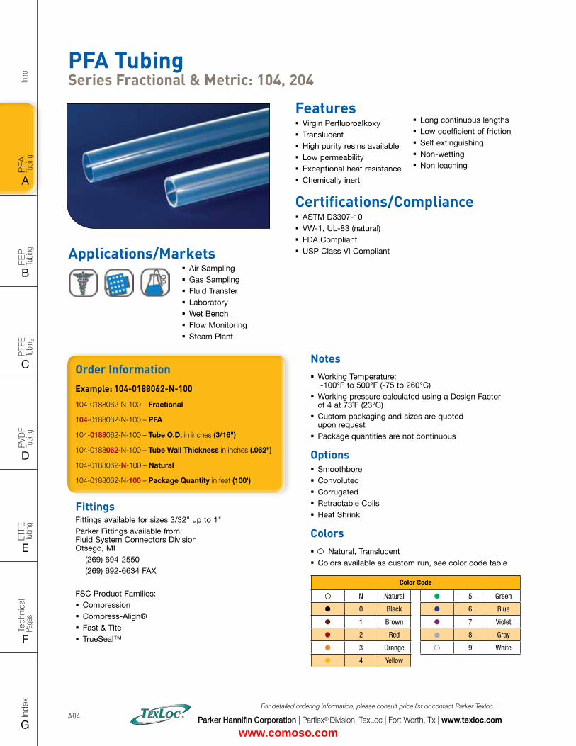
A04
Features � Virgin Perfluoroalkoxy � Translucent � High purity resins available � Low permeability � Exceptional heat resistance � Chemically inert
Certifications/Compliance � ASTM D3307-10 � VW-1, UL-83 (natural) � FDA Compliant � USP Class VI CompliantApplications/Markets
� Air Sampling � Gas Sampling � Fluid Transfer � Laboratory � Wet Bench � Flow Monitoring � Steam Plant
� Long continuous lengths � Low coefficient of friction � Self extinguishing � Non-wetting � Non leaching
PFA Tubing Series Fractional & Metric: 104, 204
FittingsFittings available for sizes 3/32" up to 1" Parker Fittings available from: Fluid System Connectors Division Otsego, MI (269) 694-2550 (269) 692-6634 FAX
FSC Product Families: � Compression � Compress-Align® � Fast & Tite � TrueSeal™
Order InformationExample: 104-0188062-N-100
104-0188062-N-100 – Fractional
104-0188062-N-100 – PFA
104-0188062-N-100 – Tube O.D. in inches (3/16")
104-0188062-N-100 – Tube Wall Thickness in inches (.062")
104-0188062-N-100 – Natural
104-0188062-N-100 – Package Quantity in feet (100')
Notes � Working Temperature: -100°F to 500°F (-75 to 260°C)
� Working pressure calculated using a Design Factor of 4 at 73˚F (23°C)
� Custom packaging and sizes are quoted upon request
� Package quantities are not continuous
Options � Smoothbore � Convoluted � Corrugated � Retractable Coils � Heat Shrink
Colors � Natural, Translucent � Colors available as custom run, see color code table
Color Code
N Natural 5 Green
0 Black 6 Blue
1 Brown 7 Violet
2 Red 8 Gray
3 Orange 9 White
4 Yellow
www.comoso.com
FLAT SIZE – 8.5" X 11" (11 x 17 spreads to be separated during final gather)CUT SIZE – 8.5" X 11"BLEED SIZE – 8.75” X 11.25”FINISHINGS – Drill holes
Intro
PFA
Tu
bing
A
FEP
Tu
bing
B
PVD
F
Tubi
ng
D
PTFE
Tu
bing
C
Index
G
Tech
nica
l Pa
ges
F
ETFE
Tu
bing
E
Parker Hannifin Corporation | Parflex® Division, TexLoc | Fort Worth, Tx | www.texloc.com
For detailed ordering information, please consult price list or contact Parker Texloc.
A05
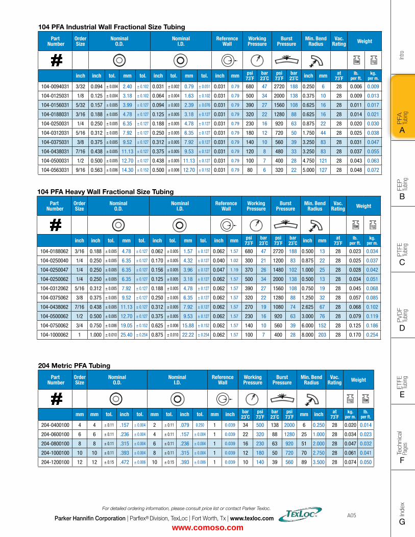
104 PFA Industrial Wall Fractional Size Tubing
Part Number
Order Size
Nominal O.D.
Nominal I.D.
Reference Wall
Working Pressure
Burst Pressure
Min. Bend Radius
Vac. Rating Weight
inch inch tol. mm tol. inch tol. mm tol. inch mm psi73˚F
bar23˚C
psi73˚F
bar23˚C inch mm at
73˚Flb.
per ft.kg.
per m.
104-0094031 3/32 0.094 ± 0.004 2.40 ± 0.102 0.031 ± 0.002 0.79 ± 0.051 0.031 0.79 680 47 2720 188 0.250 6 28 0.006 0.009
104-0125031 1/8 0.125 ± 0.004 3.18 ± 0.102 0.064 ± 0.004 1.63 ± 0.102 0.031 0.79 500 34 2000 138 0.375 10 28 0.009 0.013
104-0156031 5/32 0.157 ± 0.005 3.99 ± 0.127 0.094 ± 0.003 2.39 ± 0.076 0.031 0.79 390 27 1560 108 0.625 16 28 0.011 0.017
104-0188031 3/16 0.188 ± 0.005 4.78 ± 0.127 0.125 ± 0.005 3.18 ± 0.127 0.031 0.79 320 22 1280 88 0.625 16 28 0.014 0.021
104-0250031 1/4 0.250 ± 0.005 6.35 ± 0.127 0.188 ± 0.005 4.78 ± 0.127 0.031 0.79 230 16 920 63 0.875 22 28 0.020 0.030
104-0312031 5/16 0.312 ± 0.005 7.92 ± 0.127 0.250 ± 0.005 6.35 ± 0.127 0.031 0.79 180 12 720 50 1.750 44 28 0.025 0.038
104-0375031 3/8 0.375 ± 0.005 9.52 ± 0.127 0.312 ± 0.005 7.92 ± 0.127 0.031 0.79 140 10 560 39 3.250 83 28 0.031 0.047
104-0438031 7/16 0.438 ± 0.005 11.13 ± 0.127 0.375 ± 0.005 9.53 ± 0.127 0.031 0.79 120 8 480 33 3.250 83 28 0.037 0.055
104-0500031 1/2 0.500 ± 0.005 12.70 ± 0.127 0.438 ± 0.005 11.13 ± 0.127 0.031 0.79 100 7 400 28 4.750 121 28 0.043 0.063
104-0563031 9/16 0.563 ± 0.006 14.30 ± 0.152 0.500 ± 0.006 12.70 ± 0.152 0.031 0.79 80 6 320 22 5.000 127 28 0.048 0.072
104 PFA Heavy Wall Fractional Size Tubing
Part Number
Order Size
Nominal O.D.
Nominal I.D.
Reference Wall
Working Pressure
Burst Pressure
Min. Bend Radius
Vac. Rating Weight
inch inch tol. mm tol. inch tol. mm tol. inch mm psi73˚F
bar23˚C
psi73˚F
bar23˚C inch mm at
73˚Flb.
per ft.kg.
per m.
104-0188062 3/16 0.188 ± 0.005 4.78 ± 0.127 0.062 ± 0.005 1.57 ± 0.127 0.062 1.57 680 47 2720 188 0.500 13 28 0.023 0.034
104-0250040 1/4 0.250 ± 0.005 6.35 ± 0.127 0.170 ± 0.005 4.32 ± 0.127 0.040 1.02 300 21 1200 83 0.875 22 28 0.025 0.037
104-0250047 1/4 0.250 ± 0.005 6.35 ± 0.127 0.156 ± 0.005 3.96 ± 0.127 0.047 1.19 370 26 1480 102 1.000 25 28 0.028 0.042
104-0250062 1/4 0.250 ± 0.005 6.35 ± 0.127 0.125 ± 0.005 3.18 ± 0.127 0.062 1.57 500 34 2000 138 0.500 13 28 0.034 0.051
104-0312062 5/16 0.312 ± 0.005 7.92 ± 0.127 0.188 ± 0.005 4.78 ± 0.127 0.062 1.57 390 27 1560 108 0.750 19 28 0.045 0.068
104-0375062 3/8 0.375 ± 0.005 9.52 ± 0.127 0.250 ± 0.005 6.35 ± 0.127 0.062 1.57 320 22 1280 88 1.250 32 28 0.057 0.085
104-0438062 7/16 0.438 ± 0.005 11.13 ± 0.127 0.312 ± 0.005 7.92 ± 0.127 0.062 1.57 270 19 1080 74 2.625 67 28 0.068 0.102
104-0500062 1/2 0.500 ± 0.005 12.70 ± 0.127 0.375 ± 0.005 9.53 ± 0.127 0.062 1.57 230 16 920 63 3.000 76 28 0.079 0.119
104-0750062 3/4 0.750 ± 0.006 19.05 ± 0.152 0.625 ± 0.006 15.88 ± 0.152 0.062 1.57 140 10 560 39 6.000 152 28 0.125 0.186
104-1000062 1 1.000 ± 0.010 25.40 ± 0.254 0.875 ± 0.010 22.22 ± 0.254 0.062 1.57 100 7 400 28 8.000 203 28 0.170 0.254
204 Metric PFA Tubing
Part Number
Order Size
Nominal O.D.
Nominal I.D.
Reference Wall
Working Pressure
Burst Pressure
Min. Bend Radius
Vac. Rating Weight
mm mm tol. inch tol. mm tol. inch tol. mm inch bar23˚C
psi73˚F
bar23˚C
psi73˚F mm inch at
73˚Fkg.
per m.lb.
per ft.
204-0400100 4 4 ± 0.11 .157 ± 0.004 2 ± 0.11 .079 0.250 1 0.039 34 500 138 2000 6 0.250 28 0.020 0.014
204-0600100 6 6 ± 0.11 .236 ± 0.004 4 ± 0.11 .157 ± 0.004 1 0.039 22 320 88 1280 25 1.000 28 0.034 0.023
204-0800100 8 8 ± 0.11 .315 ± 0.004 6 ± 0.11 .236 ± 0.004 1 0.039 16 230 63 920 51 2.000 28 0.047 0.032
204-1000100 10 10 ± 0.11 .393 ± 0.004 8 ± 0.11 .315 ± 0.004 1 0.039 12 180 50 720 70 2.750 28 0.061 0.041
204-1200100 12 12 ± 0.15 .472 ± 0.006 10 ± 0.15 .393 ± 0.006 1 0.039 10 140 39 560 89 3.500 28 0.074 0.050
www.comoso.com
Intro
PFA
Tu
bing
A
FEP
Tu
bing
B
PVD
F
Tubi
ng
D
PTFE
Tu
bing
C
Index
G
Tech
nica
l Pa
ges
F
ETFE
Tu
bing
E
Parker Hannifin Corporation | Parflex® Division, TexLoc | Fort Worth, Tx | www.texloc.com
For detailed ordering information, please consult price list or contact Parker Texloc.
A06
Notes
www.comoso.com

FLAT SIZE – 8.5" X 11" (11 x 17 spreads to be separated during final gather)CUT SIZE – 8.5" X 11"BLEED SIZE – 8.75” X 11.25”FINISHINGS – Drill holes
Intro
PFA
Tu
bing
A
FEP
Tu
bing
B
PVD
F
Tubi
ng
D
PTFE
Tu
bing
C
Index
G
Tech
nica
l Pa
ges
F
ETFE
Tu
bing
E
PFA PRODUCTS
PFA Smoothbore Industrial Wall Heavy Wall Metric High Purity Smoothbore Industrial Wall Heavy Wall Metric
Retractable Coils, Convoluted and Corrugated Tubing are located in the FEP Section
PFA PRODUCTS
PFA Smoothbore Industrial Wall Heavy Wall Metric High Purity Smoothbore Industrial Wall Heavy Wall Metric
Retractable Coils, Convoluted and Corrugated Tubing are located in the FEP Section
FEP PRODUCTS
FEP (Fluorinated Ethylene Propylene)Working Temperature: 400°F (204°C) Color: Clear
• Excellent chemical resistance• Nonwetting• Weldable• Tubes can be sealed by melting• Long continuous lengths• Low refractive index• Improved clarity over PFA• Lower cost alternative to PFA
Smoothbore Fractional Industrial Wall Fractional Heavy Wall Metric Heat Shrink 1.3:1 1.67:1 1.25:1 Roll Cover Double Shrink
Convoluted FEP Convoluted Convo-Flon SAE AS81914/3
Corrugated
Retractable Coils
www.comoso.com
Intro
PFA
Tu
bing
A
FEP
Tu
bing
B
PVD
F
Tubi
ng
D
PTFE
Tu
bing
C
Index
G
Tech
nica
l Pa
ges
F
ETFE
Tu
bing
E
Parker Hannifin Corporation | Parflex® Division, TexLoc | Fort Worth, Tx | www.texloc.com
For detailed ordering information, please consult price list or contact Parker Texloc.
B02
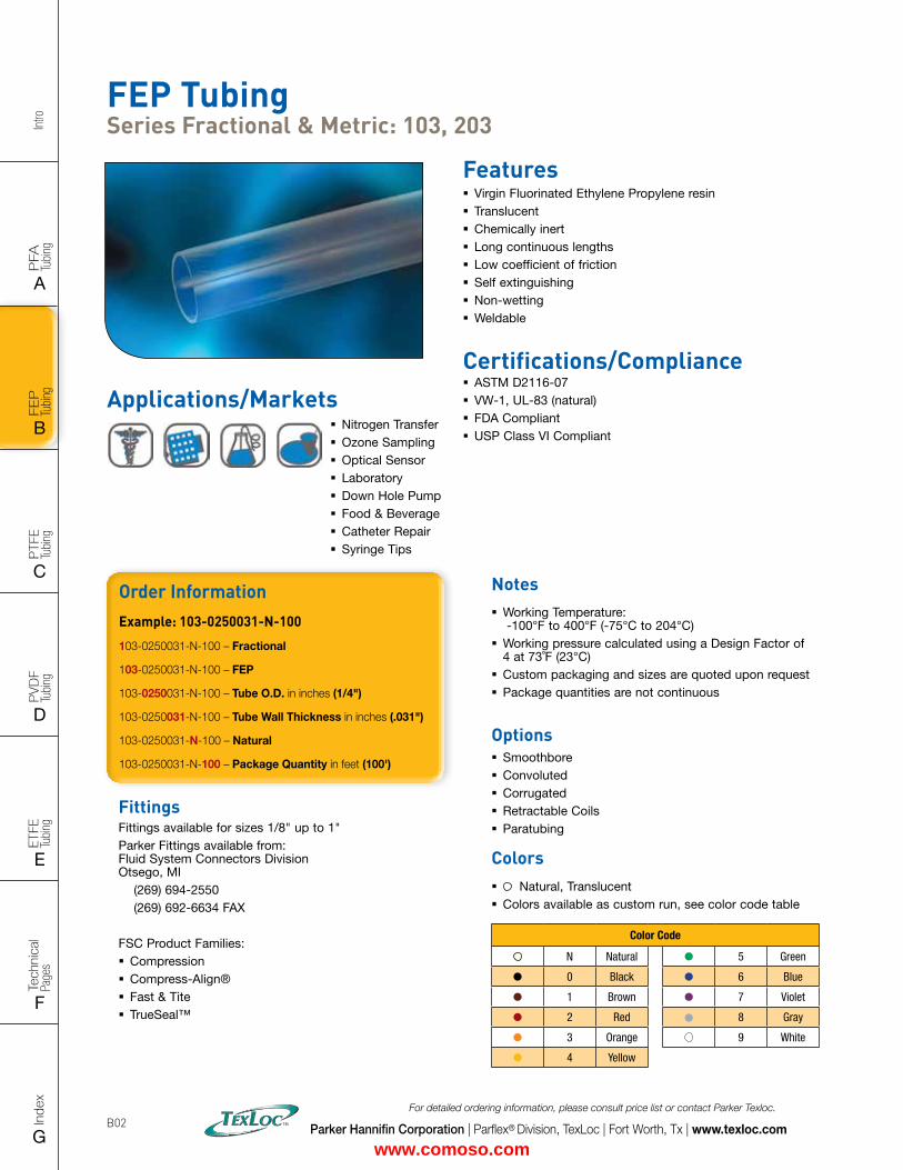
FEP Tubing Series Fractional & Metric: 103, 203
Features � Virgin Fluorinated Ethylene Propylene resin � Translucent � Chemically inert � Long continuous lengths � Low coefficient of friction � Self extinguishing � Non-wetting � Weldable
Applications/Markets � Nitrogen Transfer � Ozone Sampling � Optical Sensor � Laboratory � Down Hole Pump � Food & Beverage � Catheter Repair � Syringe Tips
Certifications/Compliance � ASTM D2116-07 � VW-1, UL-83 (natural) � FDA Compliant � USP Class VI Compliant
Order InformationExample: 103-0250031-N-100
103-0250031-N-100 – Fractional
103-0250031-N-100 – FEP
103-0250031-N-100 – Tube O.D. in inches (1/4")
103-0250031-N-100 – Tube Wall Thickness in inches (.031")
103-0250031-N-100 – Natural
103-0250031-N-100 – Package Quantity in feet (100')
FittingsFittings available for sizes 1/8" up to 1" Parker Fittings available from: Fluid System Connectors Division Otsego, MI (269) 694-2550 (269) 692-6634 FAX
FSC Product Families: � Compression � Compress-Align® � Fast & Tite � TrueSeal™
Notes � Working Temperature: -100°F to 400°F (-75°C to 204°C)
� Working pressure calculated using a Design Factor of 4 at 73˚F (23°C)
� Custom packaging and sizes are quoted upon request � Package quantities are not continuous
Options � Smoothbore � Convoluted � Corrugated � Retractable Coils � Paratubing
Colors � Natural, Translucent � Colors available as custom run, see color code table
Color Code
N Natural 5 Green
0 Black 6 Blue
1 Brown 7 Violet
2 Red 8 Gray
3 Orange 9 White
4 Yellow
www.comoso.com
FLAT SIZE – 8.5" X 11" (11 x 17 spreads to be separated during final gather)CUT SIZE – 8.5" X 11"BLEED SIZE – 8.75” X 11.25”FINISHINGS – Drill holes
Intro
PFA
Tu
bing
A
FEP
Tu
bing
B
PVD
F
Tubi
ng
D
PTFE
Tu
bing
C
Index
G
Tech
nica
l Pa
ges
F
ETFE
Tu
bing
E
Parker Hannifin Corporation | Parflex® Division, TexLoc | Fort Worth, Tx | www.texloc.com
For detailed ordering information, please consult price list or contact Parker Texloc.
B03
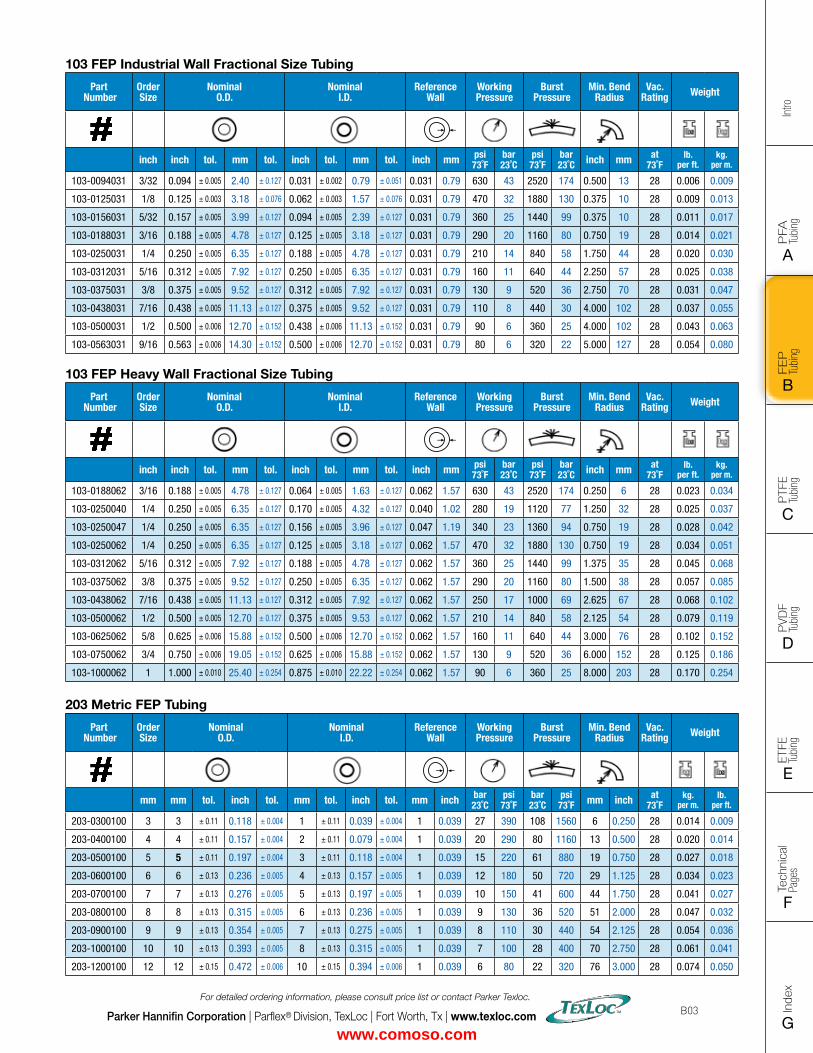
103 FEP Industrial Wall Fractional Size Tubing
Part Number
Order Size
Nominal O.D.
Nominal I.D.
Reference Wall
Working Pressure
Burst Pressure
Min. Bend Radius
Vac. Rating Weight
inch inch tol. mm tol. inch tol. mm tol. inch mm psi73˚F
bar23˚C
psi73˚F
bar23˚C inch mm at
73˚Flb.
per ft.kg.
per m.
103-0094031 3/32 0.094 ± 0.005 2.40 ± 0.127 0.031 ± 0.002 0.79 ± 0.051 0.031 0.79 630 43 2520 174 0.500 13 28 0.006 0.009
103-0125031 1/8 0.125 ± 0.003 3.18 ± 0.076 0.062 ± 0.003 1.57 ± 0.076 0.031 0.79 470 32 1880 130 0.375 10 28 0.009 0.013
103-0156031 5/32 0.157 ± 0.005 3.99 ± 0.127 0.094 ± 0.005 2.39 ± 0.127 0.031 0.79 360 25 1440 99 0.375 10 28 0.011 0.017
103-0188031 3/16 0.188 ± 0.005 4.78 ± 0.127 0.125 ± 0.005 3.18 ± 0.127 0.031 0.79 290 20 1160 80 0.750 19 28 0.014 0.021
103-0250031 1/4 0.250 ± 0.005 6.35 ± 0.127 0.188 ± 0.005 4.78 ± 0.127 0.031 0.79 210 14 840 58 1.750 44 28 0.020 0.030
103-0312031 5/16 0.312 ± 0.005 7.92 ± 0.127 0.250 ± 0.005 6.35 ± 0.127 0.031 0.79 160 11 640 44 2.250 57 28 0.025 0.038
103-0375031 3/8 0.375 ± 0.005 9.52 ± 0.127 0.312 ± 0.005 7.92 ± 0.127 0.031 0.79 130 9 520 36 2.750 70 28 0.031 0.047
103-0438031 7/16 0.438 ± 0.005 11.13 ± 0.127 0.375 ± 0.005 9.52 ± 0.127 0.031 0.79 110 8 440 30 4.000 102 28 0.037 0.055
103-0500031 1/2 0.500 ± 0.006 12.70 ± 0.152 0.438 ± 0.006 11.13 ± 0.152 0.031 0.79 90 6 360 25 4.000 102 28 0.043 0.063
103-0563031 9/16 0.563 ± 0.006 14.30 ± 0.152 0.500 ± 0.006 12.70 ± 0.152 0.031 0.79 80 6 320 22 5.000 127 28 0.054 0.080
103 FEP Heavy Wall Fractional Size Tubing
Part Number
Order Size
Nominal O.D.
Nominal I.D.
Reference Wall
Working Pressure
Burst Pressure
Min. Bend Radius
Vac. Rating Weight
inch inch tol. mm tol. inch tol. mm tol. inch mm psi73˚F
bar23˚C
psi73˚F
bar23˚C inch mm at
73˚Flb.
per ft.kg.
per m.
103-0188062 3/16 0.188 ± 0.005 4.78 ± 0.127 0.064 ± 0.005 1.63 ± 0.127 0.062 1.57 630 43 2520 174 0.250 6 28 0.023 0.034
103-0250040 1/4 0.250 ± 0.005 6.35 ± 0.127 0.170 ± 0.005 4.32 ± 0.127 0.040 1.02 280 19 1120 77 1.250 32 28 0.025 0.037
103-0250047 1/4 0.250 ± 0.005 6.35 ± 0.127 0.156 ± 0.005 3.96 ± 0.127 0.047 1.19 340 23 1360 94 0.750 19 28 0.028 0.042
103-0250062 1/4 0.250 ± 0.005 6.35 ± 0.127 0.125 ± 0.005 3.18 ± 0.127 0.062 1.57 470 32 1880 130 0.750 19 28 0.034 0.051
103-0312062 5/16 0.312 ± 0.005 7.92 ± 0.127 0.188 ± 0.005 4.78 ± 0.127 0.062 1.57 360 25 1440 99 1.375 35 28 0.045 0.068
103-0375062 3/8 0.375 ± 0.005 9.52 ± 0.127 0.250 ± 0.005 6.35 ± 0.127 0.062 1.57 290 20 1160 80 1.500 38 28 0.057 0.085
103-0438062 7/16 0.438 ± 0.005 11.13 ± 0.127 0.312 ± 0.005 7.92 ± 0.127 0.062 1.57 250 17 1000 69 2.625 67 28 0.068 0.102
103-0500062 1/2 0.500 ± 0.005 12.70 ± 0.127 0.375 ± 0.005 9.53 ± 0.127 0.062 1.57 210 14 840 58 2.125 54 28 0.079 0.119
103-0625062 5/8 0.625 ± 0.006 15.88 ± 0.152 0.500 ± 0.006 12.70 ± 0.152 0.062 1.57 160 11 640 44 3.000 76 28 0.102 0.152
103-0750062 3/4 0.750 ± 0.006 19.05 ± 0.152 0.625 ± 0.006 15.88 ± 0.152 0.062 1.57 130 9 520 36 6.000 152 28 0.125 0.186
103-1000062 1 1.000 ± 0.010 25.40 ± 0.254 0.875 ± 0.010 22.22 ± 0.254 0.062 1.57 90 6 360 25 8.000 203 28 0.170 0.254
203 Metric FEP Tubing
Part Number
Order Size
Nominal O.D.
Nominal I.D.
Reference Wall
Working Pressure
Burst Pressure
Min. Bend Radius
Vac. Rating Weight
mm mm tol. inch tol. mm tol. inch tol. mm inch bar23˚C
psi73˚F
bar23˚C
psi73˚F mm inch at
73˚Fkg.
per m.lb.
per ft.
203-0300100 3 3 ± 0.11 0.118 ± 0.004 1 ± 0.11 0.039 ± 0.004 1 0.039 27 390 108 1560 6 0.250 28 0.014 0.009
203-0400100 4 4 ± 0.11 0.157 ± 0.004 2 ± 0.11 0.079 ± 0.004 1 0.039 20 290 80 1160 13 0.500 28 0.020 0.014
203-0500100 5 5 ± 0.11 0.197 ± 0.004 3 ± 0.11 0.118 ± 0.004 1 0.039 15 220 61 880 19 0.750 28 0.027 0.018
203-0600100 6 6 ± 0.13 0.236 ± 0.005 4 ± 0.13 0.157 ± 0.005 1 0.039 12 180 50 720 29 1.125 28 0.034 0.023
203-0700100 7 7 ± 0.13 0.276 ± 0.005 5 ± 0.13 0.197 ± 0.005 1 0.039 10 150 41 600 44 1.750 28 0.041 0.027
203-0800100 8 8 ± 0.13 0.315 ± 0.005 6 ± 0.13 0.236 ± 0.005 1 0.039 9 130 36 520 51 2.000 28 0.047 0.032
203-0900100 9 9 ± 0.13 0.354 ± 0.005 7 ± 0.13 0.275 ± 0.005 1 0.039 8 110 30 440 54 2.125 28 0.054 0.036
203-1000100 10 10 ± 0.13 0.393 ± 0.005 8 ± 0.13 0.315 ± 0.005 1 0.039 7 100 28 400 70 2.750 28 0.061 0.041
203-1200100 12 12 ± 0.15 0.472 ± 0.006 10 ± 0.15 0.394 ± 0.006 1 0.039 6 80 22 320 76 3.000 28 0.074 0.050
www.comoso.com
Intro
PFA
Tu
bing
A
FEP
Tu
bing
B
PVD
F
Tubi
ng
D
PTFE
Tu
bing
C
Index
G
Tech
nica
l Pa
ges
F
ETFE
Tu
bing
E
Parker Hannifin Corporation | Parflex® Division, TexLoc | Fort Worth, Tx | www.texloc.com
For detailed ordering information, please consult price list or contact Parker Texloc.
B04
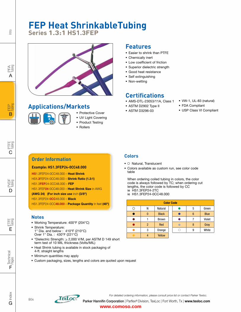
FEP Heat ShrinkableTubing Series 1.3:1 HS1.3FEP
Features � Easier to shrink than PTFE � Chemically inert � Low coefficient of friction � Superior dielectric strength � Good heat resistance � Self extinguishing � Non-wetting
Applications/Markets � Protective Cover � UV Light Covering � Product Testing � Rollers
Certifications � AMS-DTL-23053/11A, Class 1 � ASTM D2902 Type II � ASTM D3296-03
� VW-1, UL-83 (natural) � FDA Compliant � USP Class VI Compliant
Notes � Working Temperature: 400°F (204°C) � Shrink Temperature: 1" Dia. and below : 410°F (210°C) Over 1" Dia. : 430°F (221°C)
� *Dielectric Strength: > 2,000 V/M, per ASTM D 149 short term test of 10 MIL thickness (Volts/MIL)
� Heat Shrink tubing is available in stock packaging of 4-ft. straight lengths
� Minimum quantities may apply � Custom packaging, sizes, lengths and colors are quoted upon request
Order InformationExample: HS1.3FEP24-0CC48.000
HS1.3FEP24-0CC48.000 – Heat Shrink
HS1.3FEP24-0CC48.000 – Shrink Ratio (1.3:1)
HS1.3FEP24-0CC48.000 – FEP
HS1.3FEP24-0CC48.000 – Heat Shrink Size in AWG
(AWG 24) (For inch size use inch (3/8")
HS1.3FEP24-0CC48.000 – Black
HS1.3FEP24-0CC48.000 – Package Quantity in feet (48")
Colors � Natural, Translucent � Colors available as custom run, see color code table When ordering coiled tubing in colors, the color code is always followed by TC; when ordering cut lengths, the color code is followed by CC ie HS1.3FEP24-2TC ie HS1.3FEP24-0CC48.000
Color Code
N Natural 5 Green
0 Black 6 Blue
1 Brown 7 Violet
2 Red 8 Gray
3 Orange 9 White
4 Yellow
www.comoso.com
FLAT SIZE – 8.5" X 11" (11 x 17 spreads to be separated during final gather)CUT SIZE – 8.5" X 11"BLEED SIZE – 8.75” X 11.25”FINISHINGS – Drill holes
Intro
PFA
Tu
bing
A
FEP
Tu
bing
B
PVD
F
Tubi
ng
D
PTFE
Tu
bing
C
Index
G
Tech
nica
l Pa
ges
F
ETFE
Tu
bing
E
Parker Hannifin Corporation | Parflex® Division, TexLoc | Fort Worth, Tx | www.texloc.com
For detailed ordering information, please consult price list or contact Parker Texloc.
B05
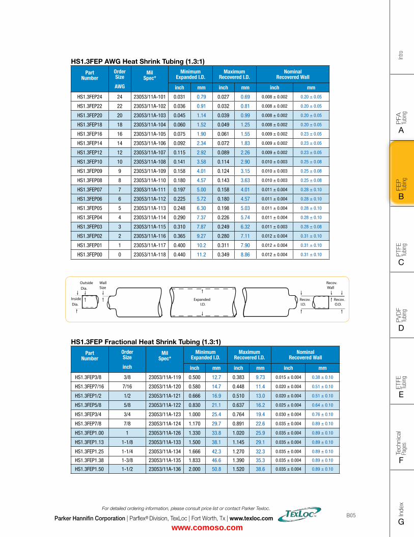
HS1.3FEP Fractional Heat Shrink Tubing (1.3:1)
Part Number
Order Size
inch
Mil Spec*
Minimum Expanded I.D.
MaximumRecovered I.D.
Nominal Recovered Wall
inch mm inch mm inch mm
HS1.3FEP3/8 3/8 23053/11A-119 0.500 12.7 0.383 9.73 0.015 ± 0.004 0.38 ± 0.10
HS1.3FEP7/16 7/16 23053/11A-120 0.580 14.7 0.448 11.4 0.020 ± 0.004 0.51 ± 0.10
HS1.3FEP1/2 1/2 23053/11A-121 0.666 16.9 0.510 13.0 0.020 ± 0.004 0.51 ± 0.10
HS1.3FEP5/8 5/8 23053/11A-122 0.830 21.1 0.637 16.2 0.025 ± 0.004 0.64 ± 0.10
HS1.3FEP3/4 3/4 23053/11A-123 1.000 25.4 0.764 19.4 0.030 ± 0.004 0.76 ± 0.10
HS1.3FEP7/8 7/8 23053/11A-124 1.170 29.7 0.891 22.6 0.035 ± 0.004 0.89 ± 0.10
HS1.3FEP1.00 1 23053/11A-126 1.330 33.8 1.020 25.9 0.035 ± 0.004 0.89 ± 0.10
HS1.3FEP1.13 1-1/8 23053/11A-133 1.500 38.1 1.145 29.1 0.035 ± 0.004 0.89 ± 0.10
HS1.3FEP1.25 1-1/4 23053/11A-134 1.666 42.3 1.270 32.3 0.035 ± 0.004 0.89 ± 0.10
HS1.3FEP1.38 1-3/8 23053/11A-135 1.833 46.6 1.390 35.3 0.035 ± 0.004 0.89 ± 0.10
HS1.3FEP1.50 1-1/2 23053/11A-136 2.000 50.8 1.520 38.6 0.035 ± 0.004 0.89 ± 0.10
Recov. Wall
Recov. O.D.
Outside Dia.
Inside Dia.
WallSize
Recov. I.D.
Expanded I.D.
HS1.3FEP AWG Heat Shrink Tubing (1.3:1)
Part Number
Order Size
AWG
Mil Spec*
Minimum Expanded I.D.
MaximumRecovered I.D.
Nominal Recovered Wall
inch mm inch mm inch mm
HS1.3FEP24 24 23053/11A-101 0.031 0.79 0.027 0.69 0.008 ± 0.002 0.20 ± 0.05
HS1.3FEP22 22 23053/11A-102 0.036 0.91 0.032 0.81 0.008 ± 0.002 0.20 ± 0.05
HS1.3FEP20 20 23053/11A-103 0.045 1.14 0.039 0.99 0.008 ± 0.002 0.20 ± 0.05
HS1.3FEP18 18 23053/11A-104 0.060 1.52 0.049 1.25 0.008 ± 0.002 0.20 ± 0.05
HS1.3FEP16 16 23053/11A-105 0.075 1.90 0.061 1.55 0.009 ± 0.002 0.23 ± 0.05
HS1.3FEP14 14 23053/11A-106 0.092 2.34 0.072 1.83 0.009 ± 0.002 0.23 ± 0.05
HS1.3FEP12 12 23053/11A-107 0.115 2.92 0.089 2.26 0.009 ± 0.002 0.23 ± 0.05
HS1.3FEP10 10 23053/11A-108 0.141 3.58 0.114 2.90 0.010 ± 0.003 0.25 ± 0.08
HS1.3FEP09 9 23053/11A-109 0.158 4.01 0.124 3.15 0.010 ± 0.003 0.25 ± 0.08
HS1.3FEP08 8 23053/11A-110 0.180 4.57 0.143 3.63 0.010 ± 0.003 0.25 ± 0.08
HS1.3FEP07 7 23053/11A-111 0.197 5.00 0.158 4.01 0.011 ± 0.004 0.28 ± 0.10
HS1.3FEP06 6 23053/11A-112 0.225 5.72 0.180 4.57 0.011 ± 0.004 0.28 ± 0.10
HS1.3FEP05 5 23053/11A-113 0.248 6.30 0.198 5.03 0.011 ± 0.004 0.28 ± 0.10
HS1.3FEP04 4 23053/11A-114 0.290 7.37 0.226 5.74 0.011 ± 0.004 0.28 ± 0.10
HS1.3FEP03 3 23053/11A-115 0.310 7.87 0.249 6.32 0.011 ± 0.003 0.28 ± 0.08
HS1.3FEP02 2 23053/11A-116 0.365 9.27 0.280 7.11 0.012 ± 0.004 0.31 ± 0.10
HS1.3FEP01 1 23053/11A-117 0.400 10.2 0.311 7.90 0.012 ± 0.004 0.31 ± 0.10
HS1.3FEP00 0 23053/11A-118 0.440 11.2 0.349 8.86 0.012 ± 0.004 0.31 ± 0.10
www.comoso.com
Intro
PFA
Tu
bing
A
FEP
Tu
bing
B
PVD
F
Tubi
ng
D
PTFE
Tu
bing
C
Index
G
Tech
nica
l Pa
ges
F
ETFE
Tu
bing
E
Parker Hannifin Corporation | Parflex® Division, TexLoc | Fort Worth, Tx | www.texloc.com
For detailed ordering information, please consult price list or contact Parker Texloc.
B06
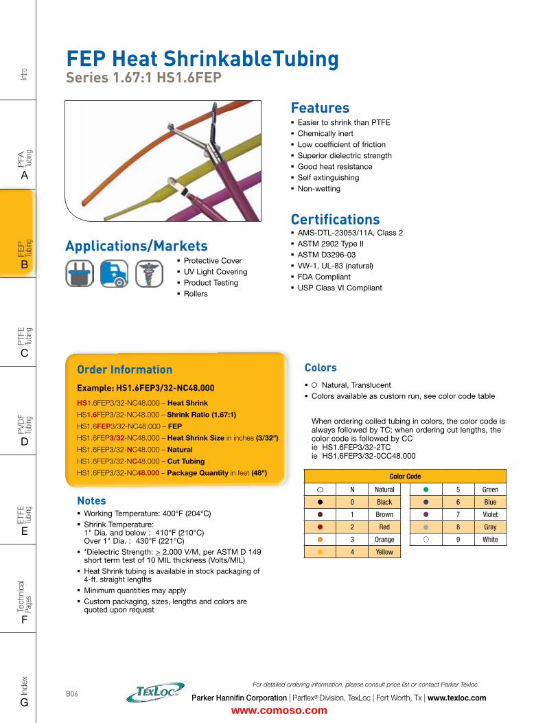
FEP Heat ShrinkableTubing Series 1.67:1 HS1.6FEP
Features � Easier to shrink than PTFE � Chemically inert � Low coefficient of friction � Superior dielectric strength � Good heat resistance � Self extinguishing � Non-wetting
Certifications � AMS-DTL-23053/11A, Class 2 � ASTM 2902 Type II � ASTM D3296-03 � VW-1, UL-83 (natural) � FDA Compliant � USP Class VI Compliant
Notes � Working Temperature: 400°F (204°C) � Shrink Temperature: 1" Dia. and below : 410°F (210°C) Over 1" Dia. : 430°F (221°C)
� *Dielectric Strength: > 2,000 V/M, per ASTM D 149 short term test of 10 MIL thickness (Volts/MIL)
� Heat Shrink tubing is available in stock packaging of 4-ft. straight lengths
� Minimum quantities may apply � Custom packaging, sizes, lengths and colors are quoted upon request
Order InformationExample: HS1.6FEP3/32-NC48.000
HS1.6FEP3/32-NC48.000 – Heat Shrink
HS1.6FEP3/32-NC48.000 – Shrink Ratio (1.67:1)
HS1.6FEP3/32-NC48.000 – FEP
HS1.6FEP3/32-NC48.000 – Heat Shrink Size in inches (3/32")
HS1.6FEP3/32-NC48.000 – Natural
HS1.6FEP3/32-NC48.000 – Cut Tubing
HS1.6FEP3/32-NC48.000 – Package Quantity in feet (48")
Colors � Natural, Translucent � Colors available as custom run, see color code table When ordering coiled tubing in colors, the color code is always followed by TC; when ordering cut lengths, the color code is followed by CC ie HS1.6FEP3/32-2TC ie HS1.6FEP3/32-0CC48.000
Color Code
N Natural 5 Green
0 Black 6 Blue
1 Brown 7 Violet
2 Red 8 Gray
3 Orange 9 White
4 Yellow
Applications/Markets � Protective Cover � UV Light Covering � Product Testing � Rollers
www.comoso.com
FLAT SIZE – 8.5" X 11" (11 x 17 spreads to be separated during final gather)CUT SIZE – 8.5" X 11"BLEED SIZE – 8.75” X 11.25”FINISHINGS – Drill holes
Intro
PFA
Tu
bing
A
FEP
Tu
bing
B
PVD
F
Tubi
ng
D
PTFE
Tu
bing
C
Index
G
Tech
nica
l Pa
ges
F
ETFE
Tu
bing
E
Parker Hannifin Corporation | Parflex® Division, TexLoc | Fort Worth, Tx | www.texloc.com
For detailed ordering information, please consult price list or contact Parker Texloc.
B07
Recov. Wall
Recov. O.D.
Outside Dia.
Inside Dia.
WallSize
Recov. I.D.
Expanded I.D.
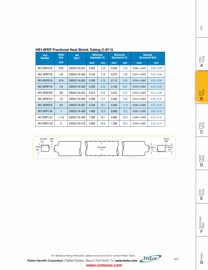
HS1.6FEP Fractional Heat Shrink Tubing (1.67:1)
Part Number
Order Size
inch
Mil Spec*
Minimum Expanded I.D.
MaximumRecovered I.D.
Nominal Recovered Wall
inch mm inch mm inch mm
HS1.6FEP3/32 3/32 23053/11A-201 0.093 2.36 0.056 1.42 0.008 ± 0.003 0.20 ± 0.08
HS1.6FEP1/8 1/8 23053/11A-202 0.125 3.18 0.075 1.90 0.010 ± 0.003 0.25 ± 0.08
HS1.6FEP3/16 3/16 23053/11A-203 0.188 4.78 0.115 2.92 0.010 ± 0.003 0.25 ± 0.08
HS1.6FEP1/4 1/4 23053/11A-204 0.250 6.35 0.150 3.81 0.010 ± 0.003 0.25 ± 0.08
HS1.6FEP3/8 3/8 23053/11A-205 0.375 9.52 0.225 5.72 0.012 ± 0.003 0.31 ± 0.08
HS1.6FEP1/2 1/2 23053/11A-206 0.500 12.7 0.300 7.62 0.015 ± 0.004 0.38 ± 0.10
HS1.6FEP3/4 3/4 23053/11A-207 0.750 19.1 0.450 11.4 0.020 ± 0.004 0.51 ± 0.10
HS1.6FEP1.00 1 23053/11A-208 1.000 25.4 0.600 15.2 0.025 ± 0.005 0.64 ± 0.13
HS1.6FEP1.25 1-1/2 23053/11A-209 1.500 38.1 0.900 22.9 0.030 ± 0.005 0.76 ± 0.13
HS1.6FEP1.50 2 23053/11A-210 2.000 50.8 1.200 30.5 0.030 ± 0.005 0.76 ± 0.13
www.comoso.com
Intro
PFA
Tu
bing
A
FEP
Tu
bing
B
PVD
F
Tubi
ng
D
PTFE
Tu
bing
C
Index
G
Tech
nica
l Pa
ges
F
ETFE
Tu
bing
E
Parker Hannifin Corporation | Parflex® Division, TexLoc | Fort Worth, Tx | www.texloc.com
For detailed ordering information, please consult price list or contact Parker Texloc.
B08
Notes � Working Temperature: 347°F (175°C) � Shrink Temperature: 347°F (175°C) for 10 minutes - For high tempera-tures 500°F (260°C), PFA roll covers are available
� Dielectric Strength: > 2,000 V/M, per ASTM D 149 short term test of 10 MIL thickness (Volts/MIL)
� Roll Cover is available in stock packaging of 4-ft. straight lengths
� Custom packaging, sizes, lengths and colors are quoted upon request
� For adhesion purposes, roll covers must be etched; Etching is available on the inside diameter, outside diameter or both
� Minimum quantities may apply
Colors � Natural, Translucent
Order InformationExample: HS1.25FEP3.50-NC48.000
HS1.25FEP3.50-NC48.000 – Heat Shrink
HS1.25FEP3.50-NC48.000 – Shrink Ratio (1.25:1)
HS1.25FEP3.50-NC48.000 – FEP
HS1.25FEP3.50-NC48.000 – Heat Shrink Expanded
Size inches (3 1/2 in)
HS1.25FEP3.50-NC48.000 – Natural
HS1.25FEP3.50-NC48.000 – Cut Tubing
HS1.25FEP3.50-NC48.000 – Package Quantity in feet (48")
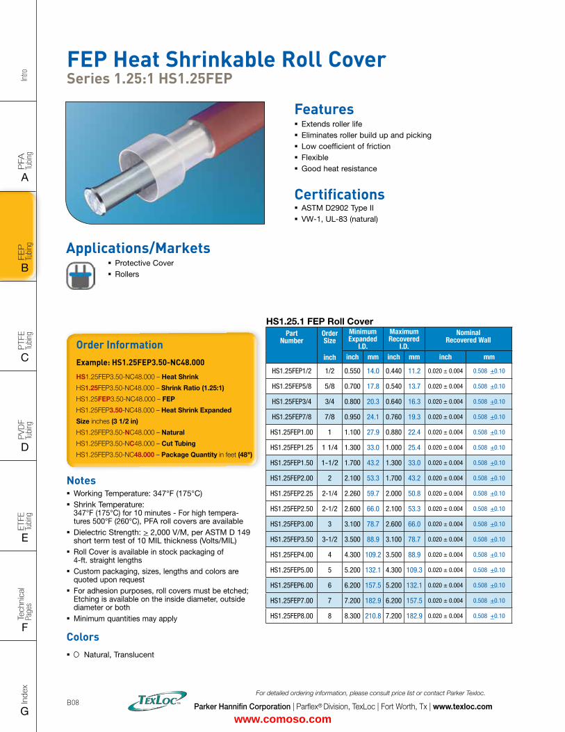
FEP Heat Shrinkable Roll Cover Series 1.25:1 HS1.25FEP
Features � Extends roller life � Eliminates roller build up and picking � Low coefficient of friction � Flexible � Good heat resistance
Certifications � ASTM D2902 Type II � VW-1, UL-83 (natural)
HS1.25.1 FEP Roll Cover Part
NumberOrder Size
inch
Minimum Expanded
I.D.
MaximumRecovered
I.D.
Nominal Recovered Wall
inch mm inch mm inch mm
HS1.25FEP1/2 1/2 0.550 14.0 0.440 11.2 0.020 ± 0.004 0.508 +0.10
HS1.25FEP5/8 5/8 0.700 17.8 0.540 13.7 0.020 ± 0.004 0.508 +0.10
HS1.25FEP3/4 3/4 0.800 20.3 0.640 16.3 0.020 ± 0.004 0.508 +0.10
HS1.25FEP7/8 7/8 0.950 24.1 0.760 19.3 0.020 ± 0.004 0.508 +0.10
HS1.25FEP1.00 1 1.100 27.9 0.880 22.4 0.020 ± 0.004 0.508 +0.10
HS1.25FEP1.25 1 1/4 1.300 33.0 1.000 25.4 0.020 ± 0.004 0.508 +0.10
HS1.25FEP1.50 1-1/2 1.700 43.2 1.300 33.0 0.020 ± 0.004 0.508 +0.10
HS1.25FEP2.00 2 2.100 53.3 1.700 43.2 0.020 ± 0.004 0.508 +0.10
HS1.25FEP2.25 2-1/4 2.260 59.7 2.000 50.8 0.020 ± 0.004 0.508 +0.10
HS1.25FEP2.50 2-1/2 2.600 66.0 2.100 53.3 0.020 ± 0.004 0.508 +0.10
HS1.25FEP3.00 3 3.100 78.7 2.600 66.0 0.020 ± 0.004 0.508 +0.10
HS1.25FEP3.50 3-1/2 3.500 88.9 3.100 78.7 0.020 ± 0.004 0.508 +0.10
HS1.25FEP4.00 4 4.300 109.2 3.500 88.9 0.020 ± 0.004 0.508 +0.10
HS1.25FEP5.00 5 5.200 132.1 4.300 109.3 0.020 ± 0.004 0.508 +0.10
HS1.25FEP6.00 6 6.200 157.5 5.200 132.1 0.020 ± 0.004 0.508 +0.10
HS1.25FEP7.00 7 7.200 182.9 6.200 157.5 0.020 ± 0.004 0.508 +0.10
HS1.25FEP8.00 8 8.300 210.8 7.200 182.9 0.020 ± 0.004 0.508 +0.10
Applications/Markets � Protective Cover � Rollers
www.comoso.com
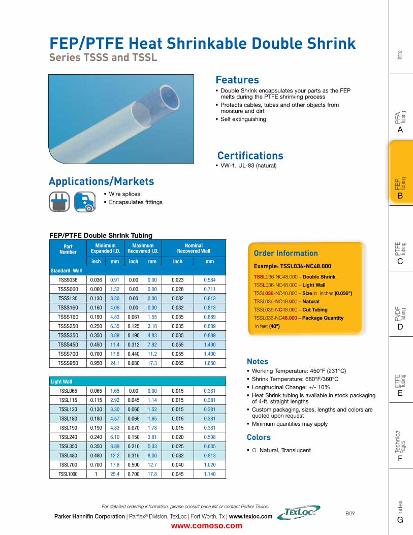
FLAT SIZE – 8.5" X 11" (11 x 17 spreads to be separated during final gather)CUT SIZE – 8.5" X 11"BLEED SIZE – 8.75” X 11.25”FINISHINGS – Drill holes
Intro
PFA
Tu
bing
A
FEP
Tu
bing
B
PVD
F
Tubi
ng
D
PTFE
Tu
bing
C
Index
G
Tech
nica
l Pa
ges
F
ETFE
Tu
bing
E
Parker Hannifin Corporation | Parflex® Division, TexLoc | Fort Worth, Tx | www.texloc.com
For detailed ordering information, please consult price list or contact Parker Texloc.
B09
FEP/PTFE Heat Shrinkable Double Shrink Series TSSS and TSSL
Features � Double Shrink encapsulates your parts as the FEP melts during the PTFE shrinking process
� Protects cables, tubes and other objects from moisture and dirt
� Self extinguishing
FEP/PTFE Double Shrink Tubing
Part Number
Minimum Expanded I.D.
MaximumRecovered I.D.
Nominal Recovered Wall
inch mm inch mm inch mm
Standard Wall
TSSS036 0.036 0.91 0.00 0.00 0.023 0.584
TSSS060 0.060 1.52 0.00 0.00 0.028 0.711
TSSS130 0.130 3.30 0.00 0.00 0.032 0.813
TSSS160 0.160 4.06 0.00 0.00 0.032 0.813
TSSS190 0.190 4.83 0.061 1.55 0.035 0.889
TSSS250 0.250 6.35 0.125 3.18 0.035 0.889
TSSS350 0.350 8.89 0.190 4.83 0.035 0.889
TSSS450 0.450 11.4 0.312 7.92 0.055 1.400
TSSS700 0.700 17.8 0.440 11.2 0.055 1.400
TSSS950 0.950 24.1 0.680 17.3 0.065 1.650
Light Wall
TSSL065 0.065 1.65 0.00 0.00 0.015 0.381
TSSL115 0.115 2.92 0.045 1.14 0.015 0.381
TSSL130 0.130 3.30 0.060 1.52 0.015 0.381
TSSL180 0.180 4.57 0.065 1.65 0.015 0.381
TSSL190 0.190 4.83 0.070 1.78 0.015 0.381
TSSL240 0.240 6.10 0.150 3.81 0.020 0.508
TSSL350 0.350 8.89 0.210 5.33 0.025 0.635
TSSL480 0.480 12.2 0.315 8.00 0.032 0.813
TSSL700 0.700 17.8 0.500 12.7 0.040 1.020
TSSL1000 1 25.4 0.700 17.8 0.045 1.140
Applications/Markets � Wire splices � Encapsulates fittings
Notes � Working Temperature: 450°F (231°C) � Shrink Temperature: 680°F/360°C � Longitudinal Change: +/- 10% � Heat Shrink tubing is available in stock packaging of 4-ft. straight lengths
� Custom packaging, sizes, lengths and colors are quoted upon request
� Minimum quantities may apply
Colors � Natural, Translucent
Order InformationExample: TSSL036-NC48.000
TSSL036-NC48.000 – Double Shrink
TSSL036-NC48.000 – Light Wall
TSSL036-NC48.000 – Size in inches (0.036")
TSSL036-NC48.000 – Natural
TSSL036-NC48.000 – Cut Tubing
TSSL036-NC48.000 – Package Quantity
in feet (48")
Certifications � VW-1, UL-83 (natural)
www.comoso.com
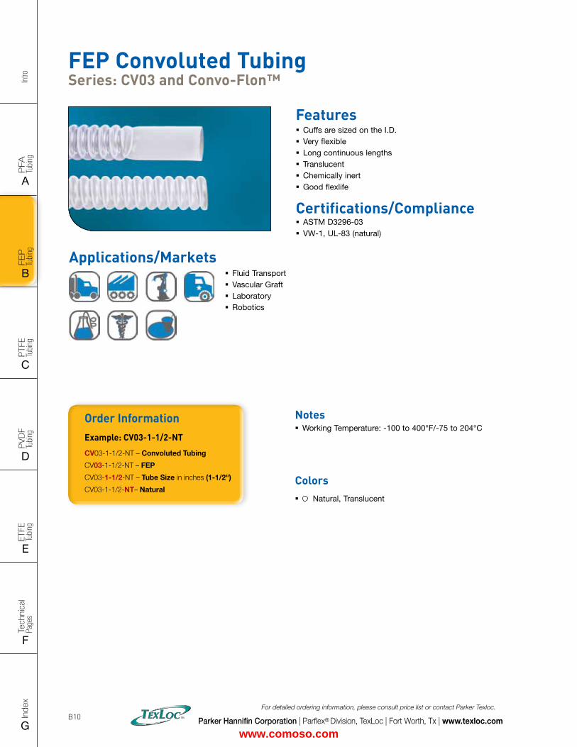
Intro
PFA
Tu
bing
A
FEP
Tu
bing
B
PVD
F
Tubi
ng
D
PTFE
Tu
bing
C
Index
G
Tech
nica
l Pa
ges
F
ETFE
Tu
bing
E
Parker Hannifin Corporation | Parflex® Division, TexLoc | Fort Worth, Tx | www.texloc.com
For detailed ordering information, please consult price list or contact Parker Texloc.
B10
Applications/Markets � Fluid Transport � Vascular Graft � Laboratory � Robotics
FEP Convoluted Tubing Series: CV03 and Convo-Flon™
Features � Cuffs are sized on the I.D. � Very flexible � Long continuous lengths � Translucent � Chemically inert � Good flexlife
Order InformationExample: CV03-1-1/2-NT
CV03-1-1/2-NT – Convoluted Tubing
CV03-1-1/2-NT – FEP
CV03-1-1/2-NT – Tube Size in inches (1-1/2")
CV03-1-1/2-NT– Natural
Certifications/Compliance � ASTM D3296-03 � VW-1, UL-83 (natural)
Notes � Working Temperature: -100 to 400°F/-75 to 204°C
Colors � Natural, Translucent
www.comoso.com
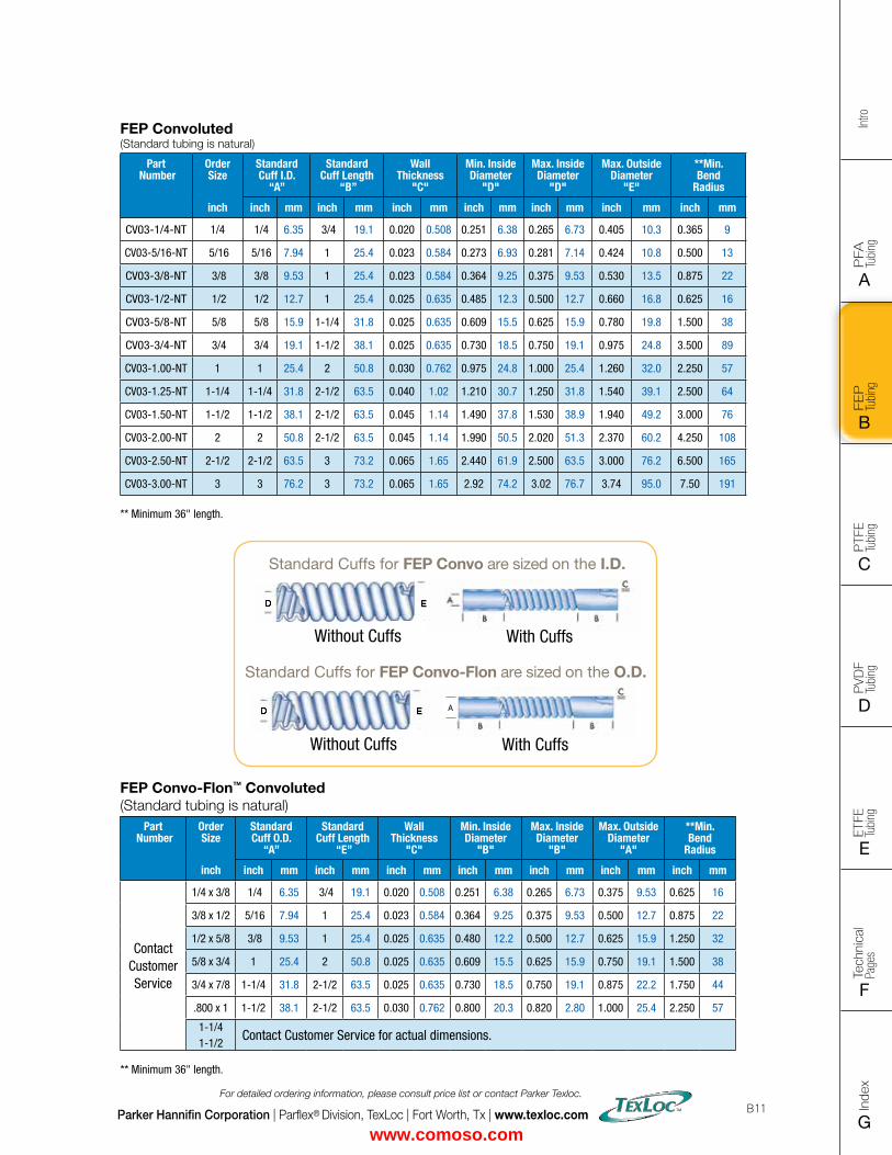
FLAT SIZE – 8.5" X 11" (11 x 17 spreads to be separated during final gather)CUT SIZE – 8.5" X 11"BLEED SIZE – 8.75” X 11.25”FINISHINGS – Drill holes
Intro
PFA
Tu
bing
A
FEP
Tu
bing
B
PVD
F
Tubi
ng
D
PTFE
Tu
bing
C
Index
G
Tech
nica
l Pa
ges
F
ETFE
Tu
bing
E
Parker Hannifin Corporation | Parflex® Division, TexLoc | Fort Worth, Tx | www.texloc.com
For detailed ordering information, please consult price list or contact Parker Texloc.
B11
FEP Convo-Flon™ Convoluted (Standard tubing is natural)
Part Number
Order Size
inch
Standard Cuff O.D.
“A”
Standard Cuff Length
“E”
Wall Thickness
"C"
Min. Inside Diameter
"B"
Max. Inside Diameter
"B"
Max. Outside Diameter
"A"
**Min. Bend
Radius
inch mm inch mm inch mm inch mm inch mm inch mm inch mm
Contact Customer Service
1/4 x 3/8 1/4 6.35 3/4 19.1 0.020 0.508 0.251 6.38 0.265 6.73 0.375 9.53 0.625 16
3/8 x 1/2 5/16 7.94 1 25.4 0.023 0.584 0.364 9.25 0.375 9.53 0.500 12.7 0.875 22
1/2 x 5/8 3/8 9.53 1 25.4 0.025 0.635 0.480 12.2 0.500 12.7 0.625 15.9 1.250 32
5/8 x 3/4 1 25.4 2 50.8 0.025 0.635 0.609 15.5 0.625 15.9 0.750 19.1 1.500 38
3/4 x 7/8 1-1/4 31.8 2-1/2 63.5 0.025 0.635 0.730 18.5 0.750 19.1 0.875 22.2 1.750 44
.800 x 1 1-1/2 38.1 2-1/2 63.5 0.030 0.762 0.800 20.3 0.820 2.80 1.000 25.4 2.250 57
1-1/41-1/2
Contact Customer Service for actual dimensions. ** Minimum 36" length.
FEP Convoluted(Standard tubing is natural)
Part Number
Order Size
inch
Standard Cuff I.D.
“A”
Standard Cuff Length
“B”
Wall Thickness
"C"
Min. Inside Diameter
"D"
Max. Inside Diameter
"D"
Max. Outside Diameter
"E"
**Min. Bend
Radius
inch mm inch mm inch mm inch mm inch mm inch mm inch mm
CV03-1/4-NT 1/4 1/4 6.35 3/4 19.1 0.020 0.508 0.251 6.38 0.265 6.73 0.405 10.3 0.365 9
CV03-5/16-NT 5/16 5/16 7.94 1 25.4 0.023 0.584 0.273 6.93 0.281 7.14 0.424 10.8 0.500 13
CV03-3/8-NT 3/8 3/8 9.53 1 25.4 0.023 0.584 0.364 9.25 0.375 9.53 0.530 13.5 0.875 22
CV03-1/2-NT 1/2 1/2 12.7 1 25.4 0.025 0.635 0.485 12.3 0.500 12.7 0.660 16.8 0.625 16
CV03-5/8-NT 5/8 5/8 15.9 1-1/4 31.8 0.025 0.635 0.609 15.5 0.625 15.9 0.780 19.8 1.500 38
CV03-3/4-NT 3/4 3/4 19.1 1-1/2 38.1 0.025 0.635 0.730 18.5 0.750 19.1 0.975 24.8 3.500 89
CV03-1.00-NT 1 1 25.4 2 50.8 0.030 0.762 0.975 24.8 1.000 25.4 1.260 32.0 2.250 57
CV03-1.25-NT 1-1/4 1-1/4 31.8 2-1/2 63.5 0.040 1.02 1.210 30.7 1.250 31.8 1.540 39.1 2.500 64
CV03-1.50-NT 1-1/2 1-1/2 38.1 2-1/2 63.5 0.045 1.14 1.490 37.8 1.530 38.9 1.940 49.2 3.000 76
CV03-2.00-NT 2 2 50.8 2-1/2 63.5 0.045 1.14 1.990 50.5 2.020 51.3 2.370 60.2 4.250 108
CV03-2.50-NT 2-1/2 2-1/2 63.5 3 73.2 0.065 1.65 2.440 61.9 2.500 63.5 3.000 76.2 6.500 165
CV03-3.00-NT 3 3 76.2 3 73.2 0.065 1.65 2.92 74.2 3.02 76.7 3.74 95.0 7.50 191 ** Minimum 36" length.
A
Standard Cuffs for FEP Convo-Flon are sized on the O.D.
With CuffsWithout Cuffs
Standard Cuffs for FEP Convo are sized on the I.D.
With CuffsWithout Cuffs
www.comoso.com
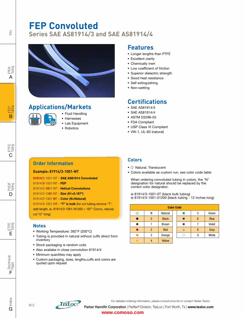
Intro
PFA
Tu
bing
A
FEP
Tu
bing
B
PVD
F
Tubi
ng
D
PTFE
Tu
bing
C
Index
G
Tech
nica
l Pa
ges
F
ETFE
Tu
bing
E
Parker Hannifin Corporation | Parflex® Division, TexLoc | Fort Worth, Tx | www.texloc.com
For detailed ordering information, please consult price list or contact Parker Texloc.
B12
FEP Convoluted Series SAE AS81914/3 and SAE AS81914/4
Features � Longer lengths than PTFE � Excellent clarity � Chemically inert � Low coefficient of friction � Superior dielectric strength � Good heat resistance � Self extinguishing � Non-wetting
Certifications � SAE AS81914/3 � SAE AS81914/4 � ASTM D3296-03 � FDA Compliant � USP Class VI Compliant � VW-1, UL-83 (natural)
Applications/Markets � Fluid Handling � Harnesses � Lab Equipment � Robotics
Order InformationExample: 81914/3-1001-NT
81914/3-1001-NT – SAE AS81914 Convoluted
81914/3-1001-NT – FEP
81914/3-1001-NT – Helical Convolutions
81914/3-1001-NT – Size (01=0.187")
81914/3-1001-NT – Color (N=Natural)
81914/3-1001-NT – "T" is bulk (for cut tubing remove "T",
add length, ie. 81914/3-1001-N1200 = 187" Convo, natural,
cut 12" long)
Notes � Working Temperature: 392°F (200°C) � Tubing is provided in natural without cuffs direct from inventory
� Stock packaging is random coils � Also availabe in close convolution 81914/4 � Minimum quantities may apply � Custom packaging, sizes, lengths,cuffs and colors are quoted upon request
Colors � Natural, Translucent � Colors available as custom run, see color code table When ordering convoluted tubing in colors, the "N" designation for natural should be replaced by the correct color designator; ie 81914/3-1001-0T (black bulk tubing) ie 81914/3-1001-01200 (black tubing - 12 inches long)
Color Code
N Natural 5 Green
0 Black 6 Blue
1 Brown 7 Violet
2 Red 8 Gray
3 Orange 9 White
4 Yellow
www.comoso.com
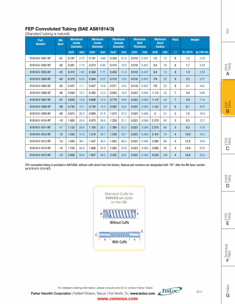
FLAT SIZE – 8.5" X 11" (11 x 17 spreads to be separated during final gather)CUT SIZE – 8.5" X 11"BLEED SIZE – 8.75” X 11.25”FINISHINGS – Drill holes
Intro
PFA
Tu
bing
A
FEP
Tu
bing
B
PVD
F
Tubi
ng
D
PTFE
Tu
bing
C
Index
G
Tech
nica
l Pa
ges
F
ETFE
Tu
bing
E
Parker Hannifin Corporation | Parflex® Division, TexLoc | Fort Worth, Tx | www.texloc.com
For detailed ordering information, please consult price list or contact Parker Texloc.
B13
Standard Cuffs for81914/3 are sized
on the I.D.
With Cuffs
Without Cuffs
FEP Convoluted Tubing (SAE AS81914/3) (Standard tubing is natural)
Part Number
MIL Spec
Maximum Inside
Diameter
Minimum Inside
Diameter
Maximum Outside
Diameter
Maximum Wall
Thickness
Minimum Bend
Radius
Pitch Weight
inch mm inch mm inch mm inch mm inch mm ±1 lb./100 ft. kg./100 mtr.
81914/3-1001-NT -01 0.187 4.75 0.181 4.60 0.320 8.13 0.018 0.457 1/2 13 8 1.5 2.23
81914/3-1002-NT -02 0.281 7.14 0.273 6.93 0.414 10.5 0.018 0.457 3/4 19 8 1.7 2.53
81914/3-1003-NT -03 0.312 7.93 0.306 7.77 0.450 11.4 0.018 0.457 3/4 19 8 1.9 2.83
81914/3-1004-NT -04 0.375 9.53 0.364 9.25 0.510 13.0 0.018 0.457 7/8 22 8 2.2 3.27
81914/3-1005-NT -05 0.437 11.1 0.427 10.9 0.571 14.5 0.018 0.457 7/8 22 8 3.1 4.61
81914/3-1006-NT -06 0.500 12.7 0.485 12.3 0.650 16.5 0.023 0.584 1-1/4 32 7 4.0 5.95
81914/3-1007-NT -07 0.625 15.9 0.608 15.4 0.770 19.6 0.023 0.584 1-1/2 38 7 4.8 7.14
81914/3-1008-NT -08 0.750 19.1 0.730 18.5 0.930 23.6 0.023 0.584 1-3/4 44 6 6.1 9.07
81914/3-1009-NT -09 0.875 22.2 0.860 21.8 1.073 27.3 0.023 0.584 2 51 5 7.0 10.4
81914/3-1010-NT -10 1.000 25.4 0.975 24.8 1.226 31.1 0.023 0.584 2.370 60 5 8.5 12.7
81914/3-1011-NT -11 1.125 28.6 1.105 28.1 1.390 35.3 0.023 0.584 2.370 60 5 9.3 13.8
81914/3-1012-NT -12 1.250 31.8 1.210 30.7 1.539 39.1 0.023 0.584 2-3/4 70 4 10.9 16.2
81914/3-1013-NT -13 1.500 38.1 1.437 36.5 1.832 46.5 0.023 0.584 3.380 86 4 12.6 18.8
81914/3-1014-NT -14 1.750 44.5 1.688 42.9 2.082 52.9 0.023 0.584 3.880 98 4 14.8 22.0
81914/3-1015-NT -15 2.000 50.8 1.937 49.2 2.332 59.2 0.023 0.584 4.250 108 4 16.8 25.0
FEP convoluted tubing is provided in NATURAL without cuffs direct from the factory. Natural part numbers are designated with “NT” after the Mil Spec number (ie 81914/3-1014-NT).
www.comoso.com
Intro
PFA
Tu
bing
A
FEP
Tu
bing
B
PVD
F
Tubi
ng
D
PTFE
Tu
bing
C
Index
G
Tech
nica
l Pa
ges
F
ETFE
Tu
bing
E
Parker Hannifin Corporation | Parflex® Division, TexLoc | Fort Worth, Tx | www.texloc.com
For detailed ordering information, please consult price list or contact Parker Texloc.
B14
Order InformationExample: CR03-3/4-NT
CR03-3/4-NT – Corrugated Tubing
CR03-3/4-NT – FEP
CR03-3/4-NT – Tube I.D. when cuffed in inches (3/4")
CR03-3/4-NT – Color (N=Natural)
CR03-3/4-NT – "T" is bulk - for cuffed tubing add length,
ie. CR03-3/4-N1200 = 1" Corr, natural, cut 12" long
Notes � Working Temperature: 200°F (93°C) @ 0 pressure - For higher temperatures, request PFA Corrugated 300°F (148°C) @ 0 pressure
� Vacuum Service: 29.9 IN. Hg (759M Hg) � Extension-Compression Length Ratio: Approximately 2:1 � Tubing is provided in natural without cuffs direct from inventory or with cuffs, as requested at time of order
� Stock packaging is random coils � Minimum quantities may apply � Corrugated tubing is also available in specialty configurations where corrugated and straight tubing run intermittently along the tube
� Custom packaging, sizes, lengths and colors are quoted upon request
FEP/PFA Corrugated Extra Flexible Fluoropolymer Tubing, Series CR03
Features � Capable of turning sharp corners without reducing the inside diameter of the tube
� Extremely flexible � Kink resistant � Non stick surface allows for easy cleaning � Excellent clarity � Chemically inert � Available in FEP, PFA and High Purity PFA
Applications/Markets � Vacuum Applications � Robotics � Instrumentation � DNA Sequencer � Fluid Transfer � Pharmaceutical � Wet Bench
Certifications � FEP - ASTM D3296-03 � PFA - ASTM D3307-10 � FDA Compliant
� USP Class VI Compliant � VW-1, UL-83 (natural)
Colors � Natural, Translucent
www.comoso.com
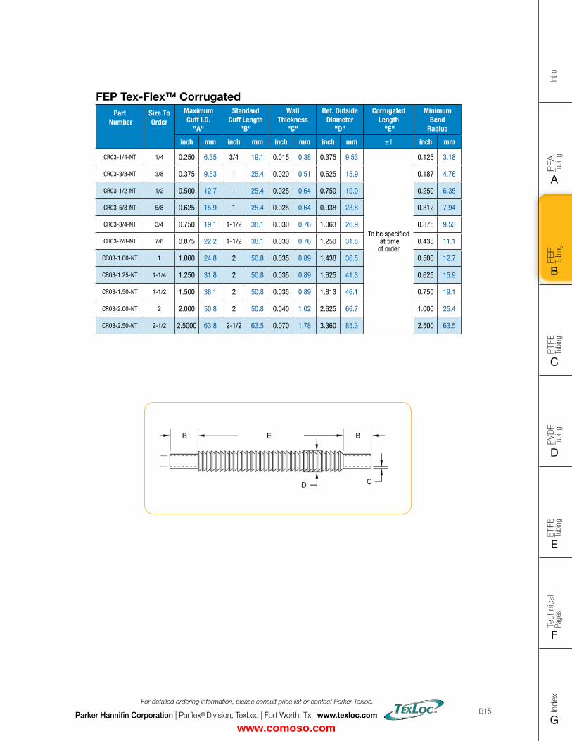
FLAT SIZE – 8.5" X 11" (11 x 17 spreads to be separated during final gather)CUT SIZE – 8.5" X 11"BLEED SIZE – 8.75” X 11.25”FINISHINGS – Drill holes
Intro
PFA
Tu
bing
A
FEP
Tu
bing
B
PVD
F
Tubi
ng
D
PTFE
Tu
bing
C
Index
G
Tech
nica
l Pa
ges
F
ETFE
Tu
bing
E
Parker Hannifin Corporation | Parflex® Division, TexLoc | Fort Worth, Tx | www.texloc.com
For detailed ordering information, please consult price list or contact Parker Texloc.
B15
FEP Tex-Flex™ CorrugatedPart
NumberSize To Order
Maximum Cuff I.D.
"A"
Standard Cuff Length
"B"
Wall Thickness
"C"
Ref. Outside Diameter
"D"
Corrugated Length
"E"
Minimum Bend
Radius
inch mm inch mm inch mm inch mm ±1 inch mm
CR03-1/4-NT 1/4 0.250 6.35 3/4 19.1 0.015 0.38 0.375 9.53
To be specified at time of order
0.125 3.18
CR03-3/8-NT 3/8 0.375 9.53 1 25.4 0.020 0.51 0.625 15.9 0.187 4.76
CR03-1/2-NT 1/2 0.500 12.7 1 25.4 0.025 0.64 0.750 19.0 0.250 6.35
CR03-5/8-NT 5/8 0.625 15.9 1 25.4 0.025 0.64 0.938 23.8 0.312 7.94
CR03-3/4-NT 3/4 0.750 19.1 1-1/2 38.1 0.030 0.76 1.063 26.9 0.375 9.53
CR03-7/8-NT 7/8 0.875 22.2 1-1/2 38.1 0.030 0.76 1.250 31.8 0.438 11.1
CR03-1.00-NT 1 1.000 24.8 2 50.8 0.035 0.89 1.438 36.5 0.500 12.7
CR03-1.25-NT 1-1/4 1.250 31.8 2 50.8 0.035 0.89 1.625 41.3 0.625 15.9
CR03-1.50-NT 1-1/2 1.500 38.1 2 50.8 0.035 0.89 1.813 46.1 0.750 19.1
CR03-2.00-NT 2 2.000 50.8 2 50.8 0.040 1.02 2.625 66.7 1.000 25.4
CR03-2.50-NT 2-1/2 2.5000 63.8 2-1/2 63.5 0.070 1.78 3.360 85.3 2.500 63.5
www.comoso.com
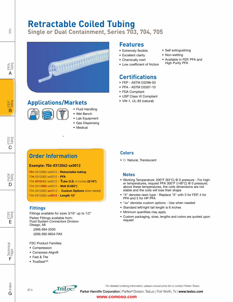
Intro
PFA
Tu
bing
A
FEP
Tu
bing
B
PVD
F
Tubi
ng
D
PTFE
Tu
bing
C
Index
G
Tech
nica
l Pa
ges
F
ETFE
Tu
bing
E
Parker Hannifin Corporation | Parflex® Division, TexLoc | Fort Worth, Tx | www.texloc.com
For detailed ordering information, please consult price list or contact Parker Texloc.
B16
Order InformationExample: 704-0312062-xx0012
704-0312062-xx0012 – Retractable tubing
704-0312062-xx0012 – PFA
704-0312062-xx0012 – Tube O.D. in inches (3/16")
704-0312062-xx0012 – Wall (0.062")
704-0312062-xx0012 – Custom Options (when needed)
704-0312062-xx0012 – Length 12"
Colors � Natural, Translucent
Notes
� Working Temperature: 200°F (93°C) @ 0 pressure - For high-er temperatures, request PFA 300°F (148°C) @ 0 pressure; above these temperatures, the coils dimensions are not stable and the coils will lose their shape
� "X" denotes resin type - Replace "X" with 3 for FEP, 4 for PFA and 5 for HP PFA
� "xx" denotes custom options - Use when needed � Standard left/right tail length is 6 inches � Minimum quantities may apply � Custom packaging, sizes, lengths and colors are quoted upon request
FittingsFittings available for sizes 3/16" up to 1/2"Parker Fittings available from: Fluid System Connectors Division Otsego, MI (269) 694-2550 (269) 692-6634 FAX
FSC Product Families: � Compression � Compress-Align® � Fast & Tite � TrueSeal™
Retractable Coiled Tubing Single or Dual Containment, Series 703, 704, 705
Certifications � FEP - ASTM D3296-03 � PFA - ASTM D3307-10 � FDA Compliant � USP Class VI Compliant � VW-1, UL-83 (natural) Applications/Markets
� Fluid Handling � Wet Bench � Lab Equipment � Gas Dispensing � Medical
Features � Extremely flexible � Excellent clarity � Chemically inert � Low coefficient of friction
� Self extinguishing � Non-wetting � Available in FEP, PFA and High Purity PFA
www.comoso.com
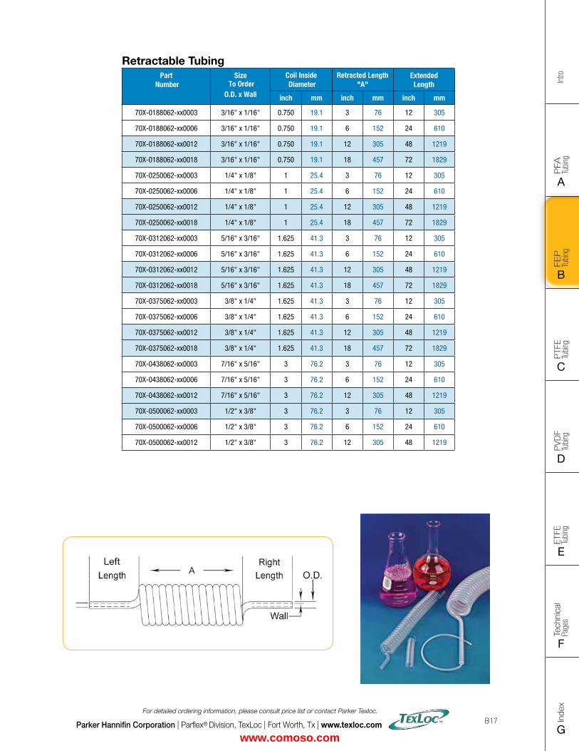
FLAT SIZE – 8.5" X 11" (11 x 17 spreads to be separated during final gather)CUT SIZE – 8.5" X 11"BLEED SIZE – 8.75” X 11.25”FINISHINGS – Drill holes
Intro
PFA
Tu
bing
A
FEP
Tu
bing
B
PVD
F
Tubi
ng
D
PTFE
Tu
bing
C
Index
G
Tech
nica
l Pa
ges
F
ETFE
Tu
bing
E
Parker Hannifin Corporation | Parflex® Division, TexLoc | Fort Worth, Tx | www.texloc.com
For detailed ordering information, please consult price list or contact Parker Texloc.
B17
Retractable TubingPart
NumberSize
To Order O.D. x Wall
Coil Inside Diameter
Retracted Length "A"
Extended Length
inch mm inch mm inch mm
70X-0188062-xx0003 3/16" x 1/16" 0.750 19.1 3 76 12 305
70X-0188062-xx0006 3/16" x 1/16" 0.750 19.1 6 152 24 610
70X-0188062-xx0012 3/16" x 1/16" 0.750 19.1 12 305 48 1219
70X-0188062-xx0018 3/16" x 1/16" 0.750 19.1 18 457 72 1829
70X-0250062-xx0003 1/4" x 1/8" 1 25.4 3 76 12 305
70X-0250062-xx0006 1/4" x 1/8" 1 25.4 6 152 24 610
70X-0250062-xx0012 1/4" x 1/8" 1 25.4 12 305 48 1219
70X-0250062-xx0018 1/4" x 1/8" 1 25.4 18 457 72 1829
70X-0312062-xx0003 5/16" x 3/16" 1.625 41.3 3 76 12 305
70X-0312062-xx0006 5/16" x 3/16" 1.625 41.3 6 152 24 610
70X-0312062-xx0012 5/16" x 3/16" 1.625 41.3 12 305 48 1219
70X-0312062-xx0018 5/16" x 3/16" 1.625 41.3 18 457 72 1829
70X-0375062-xx0003 3/8" x 1/4" 1.625 41.3 3 76 12 305
70X-0375062-xx0006 3/8" x 1/4" 1.625 41.3 6 152 24 610
70X-0375062-xx0012 3/8" x 1/4" 1.625 41.3 12 305 48 1219
70X-0375062-xx0018 3/8" x 1/4" 1.625 41.3 18 457 72 1829
70X-0438062-xx0003 7/16" x 5/16" 3 76.2 3 76 12 305
70X-0438062-xx0006 7/16" x 5/16" 3 76.2 6 152 24 610
70X-0438062-xx0012 7/16" x 5/16" 3 76.2 12 305 48 1219
70X-0500062-xx0003 1/2" x 3/8" 3 76.2 3 76 12 305
70X-0500062-xx0006 1/2" x 3/8" 3 76.2 6 152 24 610
70X-0500062-xx0012 1/2" x 3/8" 3 76.2 12 305 48 1219
www.comoso.com
Intro
PFA
Tu
bing
A
FEP
Tu
bing
B
PVD
F
Tubi
ng
D
PTFE
Tu
bing
C
Index
G
Tech
nica
l Pa
ges
F
ETFE
Tu
bing
E
Parker Hannifin Corporation | Parflex® Division, TexLoc | Fort Worth, Tx | www.texloc.com
For detailed ordering information, please consult price list or contact Parker Texloc.
B18
Notes
www.comoso.com
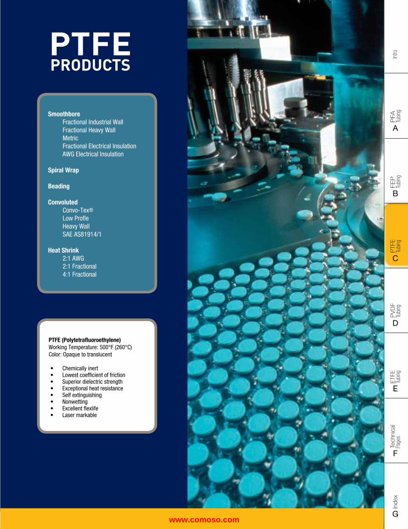
FLAT SIZE – 8.5" X 11" (11 x 17 spreads to be separated during final gather)CUT SIZE – 8.5" X 11"BLEED SIZE – 8.75” X 11.25”FINISHINGS – Drill holes
Intro
PFA
Tu
bing
A
FEP
Tu
bing
B
PVD
F
Tubi
ng
D
PTFE
Tu
bing
C
Index
G
Tech
nica
l Pa
ges
F
ETFE
Tu
bing
E
PFA PRODUCTS
PFA Smoothbore Industrial Wall Heavy Wall Metric High Purity Smoothbore Industrial Wall Heavy Wall Metric
Retractable Coils, Convoluted and Corrugated Tubing are located in the FEP Section
PFA PRODUCTS
PFA Smoothbore Industrial Wall Heavy Wall Metric High Purity Smoothbore Industrial Wall Heavy Wall Metric
Retractable Coils, Convoluted and Corrugated Tubing are located in the FEP Section
PTFE PRODUCTS
PTFE (Polytetrafluoroethylene)Working Temperature: 500°F (260°C) Color: Opaque to translucent
• Chemically inert• Lowest coefficient of friction• Superior dielectric strength• Exceptional heat resistance• Self extinguishing• Nonwetting• Excellent flexlife• Laser markable
Smoothbore Fractional Industrial Wall Fractional Heavy Wall Metric Fractional Electrical Insulation AWG Electrical Insulation Spiral Wrap Beading Convoluted Convo-Tex® Low Profle Heavy Wall SAE AS81914/1
Heat Shrink 2:1 AWG 2:1 Fractional 4:1 Fractional
www.comoso.com
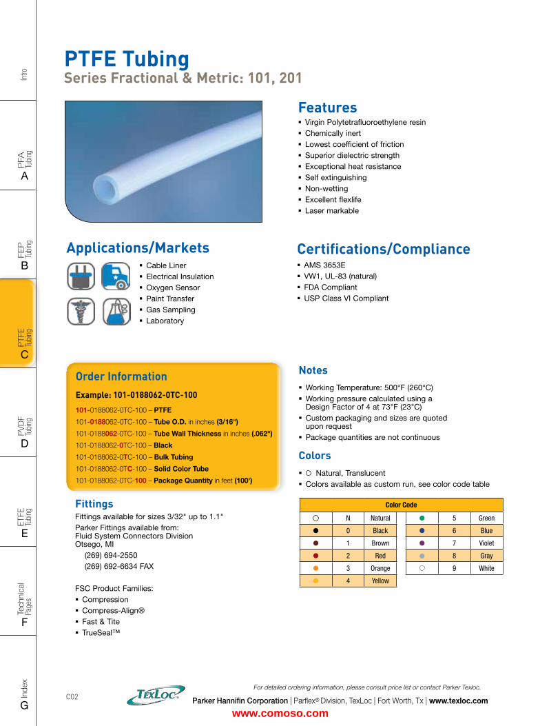
Intro
PFA
Tu
bing
A
FEP
Tu
bing
B
PVD
F
Tubi
ng
D
PTFE
Tu
bing
C
Index
G
Tech
nica
l Pa
ges
F
ETFE
Tu
bing
E
Parker Hannifin Corporation | Parflex® Division, TexLoc | Fort Worth, Tx | www.texloc.com
For detailed ordering information, please consult price list or contact Parker Texloc.
C02
PTFE Tubing Series Fractional & Metric: 101, 201
Features � Virgin Polytetrafluoroethylene resin � Chemically inert � Lowest coefficient of friction � Superior dielectric strength � Exceptional heat resistance � Self extinguishing � Non-wetting � Excellent flexlife � Laser markable
Certifications/Compliance � AMS 3653E � VW1, UL-83 (natural) � FDA Compliant � USP Class VI Compliant
Applications/Markets � Cable Liner � Electrical Insulation � Oxygen Sensor � Paint Transfer � Gas Sampling � Laboratory
FittingsFittings available for sizes 3/32" up to 1.1"Parker Fittings available from: Fluid System Connectors Division Otsego, MI (269) 694-2550 (269) 692-6634 FAX
FSC Product Families: � Compression � Compress-Align® � Fast & Tite � TrueSeal™
Order InformationExample: 101-0188062-0TC-100
101-0188062-0TC-100 – PTFE
101-0188062-0TC-100 – Tube O.D. in inches (3/16")
101-0188062-0TC-100 – Tube Wall Thickness in inches (.062")
101-0188062-0TC-100 – Black
101-0188062-0TC-100 – Bulk Tubing
101-0188062-0TC-100 – Solid Color Tube
101-0188062-0TC-100 – Package Quantity in feet (100')
Notes � Working Temperature: 500°F (260°C) � Working pressure calculated using a Design Factor of 4 at 73°F (23°C)
� Custom packaging and sizes are quoted upon request
� Package quantities are not continuous
Colors � Natural, Translucent � Colors available as custom run, see color code table
Color Code
N Natural 5 Green
0 Black 6 Blue
1 Brown 7 Violet
2 Red 8 Gray
3 Orange 9 White
4 Yellow
www.comoso.com
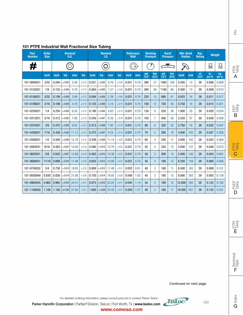
FLAT SIZE – 8.5" X 11" (11 x 17 spreads to be separated during final gather)CUT SIZE – 8.5" X 11"BLEED SIZE – 8.75” X 11.25”FINISHINGS – Drill holes
Intro
PFA
Tu
bing
A
FEP
Tu
bing
B
PVD
F
Tubi
ng
D
PTFE
Tu
bing
C
Index
G
Tech
nica
l Pa
ges
F
ETFE
Tu
bing
E
Parker Hannifin Corporation | Parflex® Division, TexLoc | Fort Worth, Tx | www.texloc.com
For detailed ordering information, please consult price list or contact Parker Texloc.
C03
101 PTFE Industrial Wall Fractional Size Tubing
Part Number
Order Size
Nominal O.D.
Nominal I.D.
Reference Wall
Working Pressure
Burst Pressure
Min. Bend Radius
Vac. Rating Weight
inch inch tol. mm tol. inch tol. mm tol. inch mm psi73˚F
bar23˚C
psi73˚F
bar23˚C inch mm at
73˚Flb.
per ft.kg.
per m.
101-0094031 3/32 0.094 ± 0.005 2.40 ± 0.13 0.031 ± 0.002 0.79 ± 0.05 0.031 0.79 390 27 1560 108 0.500 13 28 0.006 0.009
101-0125031 1/8 0.125 ± 0.005 3.18 ± 0.13 0.063 ± 0.003 1.57 ± 0.05 0.031 0.79 290 20 1160 80 0.500 13 28 0.009 0.013
101-0156031 5/32 0.156 ± 0.005 3.99 ± 0.13 0.094 ± 0.004 2.39 ± 0.08 0.031 0.79 220 15 880 61 0.625 16 28 0.011 0.017
101-0188031 3/16 0.188 ± 0.005 4.78 ± 0.13 0.125 ± 0.005 3.18 ± 0.13 0.031 0.79 180 12 720 50 0.750 19 28 0.014 0.021
101-0250031 1/4 0.250 ± 0.005 6.35 ± 0.13 0.190 ± 0.005 4.83 ± 0.13 0.031 0.79 130 9 520 36 1.000 25 28 0.020 0.030
101-0312031 5/16 0.312 ± 0.005 7.92 ± 0.13 0.250 ± 0.007 6.35 ± 0.18 0.031 0.79 100 7 400 28 2.250 57 28 0.026 0.038
101-0375031 3/8 0.375 ± 0.005 9.52 ± 0.13 0.312 ± 0.006 7.92 ± 0.15 0.031 0.79 80 6 320 22 2.750 70 28 0.032 0.047
101-0438031 7/16 0.438 ± 0.005 11.13 ± 0.13 0.375 ± 0.007 9.52 ± 0.18 0.031 0.79 70 5 280 19 4.000 102 28 0.037 0.056
101-0500031 1/2 0.500 ± 0.006 12.70 ± 0.15 0.438 ± 0.008 11.13 ± 0.20 0.031 0.79 60 4 240 17 4.000 102 28 0.043 0.064
101-0563031 9/16 0.563 ± 0.007 14.30 ± 0.18 0.500 ± 0.010 12.70 ± 0.25 0.031 0.79 55 4 220 15 5.000 127 28 0.049 0.073
101-0625031 5/8 0.625 ± 0.007 15.88 ± 0.18 0.563 ± 0.010 14.30 ± 0.25 0.031 0.79 50 3 200 14 5.500 140 28 0.054 0.081
101-0688031 11/16 0.688 ± 0.010 17.48 ± 0.25 0.625 ± 0.012 15.88 ± 0.31 0.031 0.79 45 3 180 12 6.250 159 28 0.060 0.090
101-0750032 3/4 0.750 ± 0.010 19.05 ± 0.25 0.688 ± 0.012 17.48 ± 0.31 0.032 0.81 40 3 160 11 6.500 165 28 0.068 0.101
101-0830040 0.830 0.830 ± 0.014 21.08 ± 0.36 0.750 ± 0.014 19.05 ± 0.36 0.040 1.02 45 3 180 12 8.000 203 28 0.093 0.139
101-0965045 0.965 0.965 ± 0.016 24.51 ± 0.41 0.875 ± 0.016 22.22 ± 0.41 0.045 1.14 45 3 180 12 12.000 305 28 0.122 0.182
101-1100050 1.100 1.100 ±0 .020 27.94 ± 0.51 1.000 ± 0.020 25.40 ± 0.51 0.050 1.27 40 3 160 11 18.000 457 28 0.155 0.231
Continued on next page
www.comoso.com
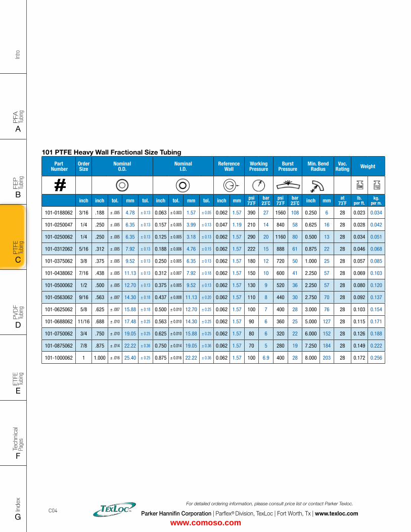
Intro
PFA
Tu
bing
A
FEP
Tu
bing
B
PVD
F
Tubi
ng
D
PTFE
Tu
bing
C
Index
G
Tech
nica
l Pa
ges
F
ETFE
Tu
bing
E
Parker Hannifin Corporation | Parflex® Division, TexLoc | Fort Worth, Tx | www.texloc.com
For detailed ordering information, please consult price list or contact Parker Texloc.
C04
101 PTFE Heavy Wall Fractional Size Tubing
Part Number
Order Size
Nominal O.D.
Nominal I.D.
Reference Wall
Working Pressure
Burst Pressure
Min. Bend Radius
Vac. Rating Weight
inch inch tol. mm tol. inch tol. mm tol. inch mm psi73˚F
bar23˚C
psi73˚F
bar23˚C inch mm at
73˚Flb.
per ft.kg.
per m.
101-0188062 3/16 .188 ± .005 4.78 ± 0.13 0.063 ± 0.003 1.57 ± 0.05 0.062 1.57 390 27 1560 108 0.250 6 28 0.023 0.034
101-0250047 1/4 .250 ± .005 6.35 ± 0.13 0.157 ± 0.005 3.99 ± 0.13 0.047 1.19 210 14 840 58 0.625 16 28 0.028 0.042
101-0250062 1/4 .250 ± .005 6.35 ± 0.13 0.125 ± 0.005 3.18 ± 0.13 0.062 1.57 290 20 1160 80 0.500 13 28 0.034 0.051
101-0312062 5/16 .312 ± .005 7.92 ± 0.13 0.188 ± 0.006 4.76 ± 0.15 0.062 1.57 222 15 888 61 0.875 22 28 0.046 0.068
101-0375062 3/8 .375 ± .005 9.52 ± 0.13 0.250 ± 0.005 6.35 ± 0.13 0.062 1.57 180 12 720 50 1.000 25 28 0.057 0.085
101-0438062 7/16 .438 ± .005 11.13 ± 0.13 0.312 ± 0.007 7.92 ± 0.18 0.062 1.57 150 10 600 41 2.250 57 28 0.069 0.103
101-0500062 1/2 .500 ± .005 12.70 ± 0.13 0.375 ± 0.005 9.52 ± 0.13 0.062 1.57 130 9 520 36 2.250 57 28 0.080 0.120
101-0563062 9/16 .563 ± .007 14.30 ± 0.18 0.437 ± 0.008 11.13 ± 0.20 0.062 1.57 110 8 440 30 2.750 70 28 0.092 0.137
101-0625062 5/8 .625 ± .007 15.88 ± 0.18 0.500 ± 0.010 12.70 ± 0.25 0.062 1.57 100 7 400 28 3.000 76 28 0.103 0.154
101-0688062 11/16 .688 ± .010 17.48 ± 0.25 0.563 ± 0.010 14.30 ± 0.25 0.062 1.57 90 6 360 25 5.000 127 28 0.115 0.171
101-0750062 3/4 .750 ± .010 19.05 ± 0.25 0.625 ± 0.010 15.88 ± 0.25 0.062 1.57 80 6 320 22 6.000 152 28 0.126 0.188
101-0875062 7/8 .875 ± .014 22.22 ± 0.36 0.750 ± 0.014 19.05 ± 0.36 0.062 1.57 70 5 280 19 7.250 184 28 0.149 0.222
101-1000062 1 1.000 ± .016 25.40 ± 0.25 0.875 ± 0.016 22.22 ± 0.36 0.062 1.57 100 6.9 400 28 8.000 203 28 0.172 0.256
www.comoso.com
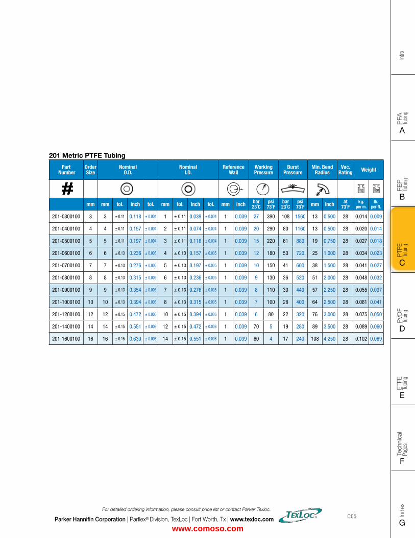
FLAT SIZE – 8.5" X 11" (11 x 17 spreads to be separated during final gather)CUT SIZE – 8.5" X 11"BLEED SIZE – 8.75” X 11.25”FINISHINGS – Drill holes
Intro
PFA
Tu
bing
A
FEP
Tu
bing
B
PVD
F
Tubi
ng
D
PTFE
Tu
bing
C
Index
G
Tech
nica
l Pa
ges
F
ETFE
Tu
bing
E
Parker Hannifin Corporation | Parflex® Division, TexLoc | Fort Worth, Tx | www.texloc.com
For detailed ordering information, please consult price list or contact Parker Texloc.
C05
201 Metric PTFE Tubing
Part Number
Order Size
Nominal O.D.
Nominal I.D.
Reference Wall
Working Pressure
Burst Pressure
Min. Bend Radius
Vac. Rating Weight
mm mm tol. inch tol. mm tol. inch tol. mm inch bar23˚C
psi73˚F
bar23˚C
psi73˚F mm inch at
73˚Fkg.
per m.lb.
per ft.
201-0300100 3 3 ± 0.11 0.118 ± 0.004 1 ± 0.11 0.039 ± 0.004 1 0.039 27 390 108 1560 13 0.500 28 0.014 0.009
201-0400100 4 4 ± 0.11 0.157 ± 0.004 2 ± 0.11 0.074 ± 0.004 1 0.039 20 290 80 1160 13 0.500 28 0.020 0.014
201-0500100 5 5 ± 0.11 0.197 ± 0.004 3 ± 0.11 0.118 ± 0.004 1 0.039 15 220 61 880 19 0.750 28 0.027 0.018
201-0600100 6 6 ± 0.13 0.236 ± 0.005 4 ± 0.13 0.157 ± 0.005 1 0.039 12 180 50 720 25 1.000 28 0.034 0.023
201-0700100 7 7 ± 0.13 0.276 ± 0.005 5 ± 0.13 0.197 ± 0.005 1 0.039 10 150 41 600 38 1.500 28 0.041 0.027
201-0800100 8 8 ± 0.13 0.315 ± 0.005 6 ± 0.13 0.236 ± 0.005 1 0.039 9 130 36 520 51 2.000 28 0.048 0.032
201-0900100 9 9 ± 0.13 0.354 ± 0.005 7 ± 0.13 0.276 ± 0.005 1 0.039 8 110 30 440 57 2.250 28 0.055 0.037
201-1000100 10 10 ± 0.13 0.394 ± 0.005 8 ± 0.13 0.315 ± 0.005 1 0.039 7 100 28 400 64 2.500 28 0.061 0.041
201-1200100 12 12 ± 0.15 0.472 ± 0.006 10 ± 0.15 0.394 ± 0.006 1 0.039 6 80 22 320 76 3.000 28 0.075 0.050
201-1400100 14 14 ± 0.15 0.551 ± 0.006 12 ± 0.15 0.472 ± 0.006 1 0.039 70 5 19 280 89 3.500 28 0.089 0.060
201-1600100 16 16 ± 0.15 0.630 ± 0.006 14 ± 0.15 0.551 ± 0.006 1 0.039 60 4 17 240 108 4.250 28 0.102 0.069
www.comoso.com
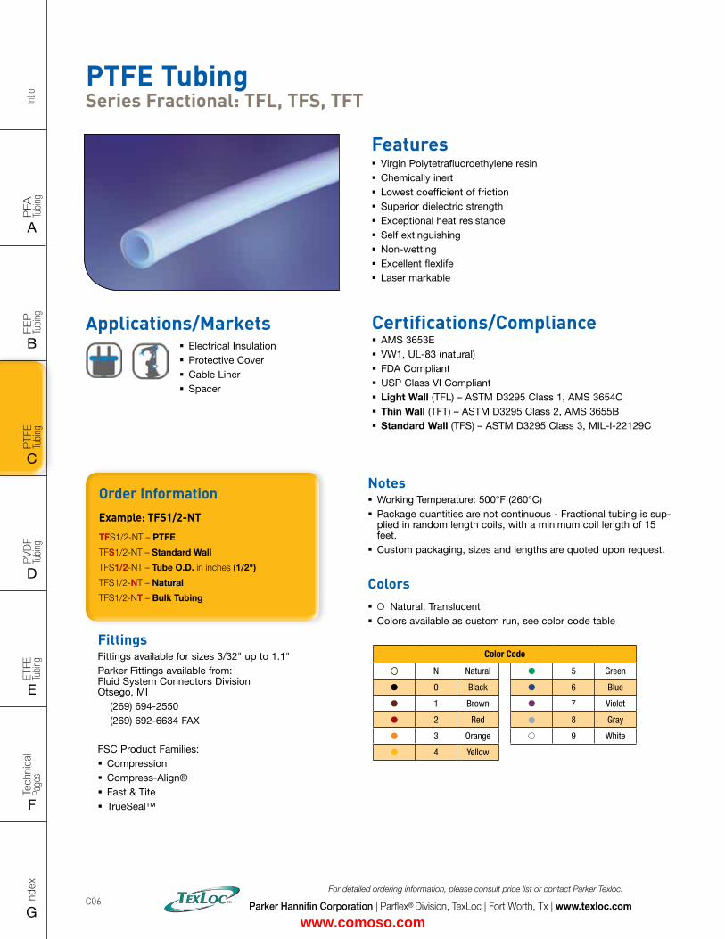
Intro
PFA
Tu
bing
A
FEP
Tu
bing
B
PVD
F
Tubi
ng
D
PTFE
Tu
bing
C
Index
G
Tech
nica
l Pa
ges
F
ETFE
Tu
bing
E
Parker Hannifin Corporation | Parflex® Division, TexLoc | Fort Worth, Tx | www.texloc.com
For detailed ordering information, please consult price list or contact Parker Texloc.
C06
PTFE Tubing Series Fractional: TFL, TFS, TFT
Features � Virgin Polytetrafluoroethylene resin � Chemically inert � Lowest coefficient of friction � Superior dielectric strength � Exceptional heat resistance � Self extinguishing � Non-wetting � Excellent flexlife � Laser markable
Certifications/Compliance � AMS 3653E � VW1, UL-83 (natural) � FDA Compliant � USP Class VI Compliant � Light Wall (TFL) – ASTM D3295 Class 1, AMS 3654C � Thin Wall (TFT) – ASTM D3295 Class 2, AMS 3655B � Standard Wall (TFS) – ASTM D3295 Class 3, MIL-I-22129C
Applications/Markets � Electrical Insulation � Protective Cover � Cable Liner � Spacer
FittingsFittings available for sizes 3/32" up to 1.1"Parker Fittings available from: Fluid System Connectors Division Otsego, MI (269) 694-2550 (269) 692-6634 FAX
FSC Product Families: � Compression � Compress-Align® � Fast & Tite � TrueSeal™
Order InformationExample: TFS1/2-NT
TFS1/2-NT – PTFE
TFS1/2-NT – Standard Wall
TFS1/2-NT – Tube O.D. in inches (1/2")
TFS1/2-NT – Natural
TFS1/2-NT – Bulk Tubing
Notes � Working Temperature: 500°F (260°C) � Package quantities are not continuous - Fractional tubing is sup-plied in random length coils, with a minimum coil length of 15 feet.
� Custom packaging, sizes and lengths are quoted upon request.
Colors � Natural, Translucent � Colors available as custom run, see color code table
Color Code
N Natural 5 Green
0 Black 6 Blue
1 Brown 7 Violet
2 Red 8 Gray
3 Orange 9 White
4 Yellow
www.comoso.com
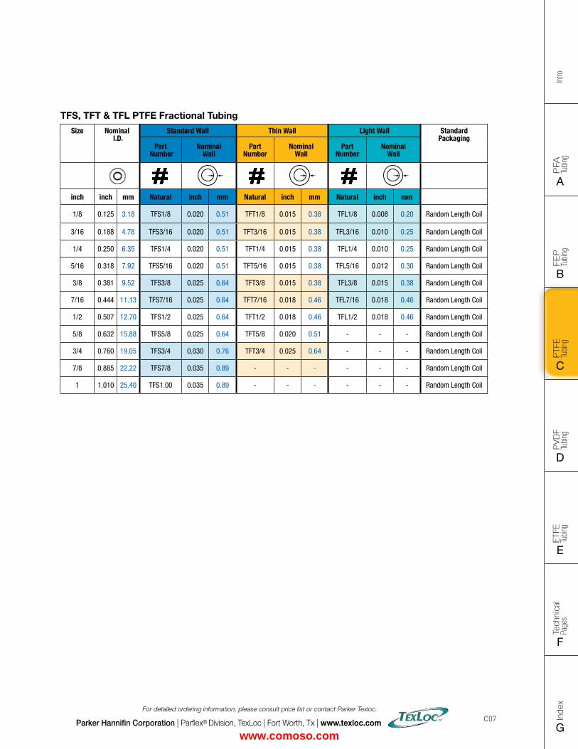
FLAT SIZE – 8.5" X 11" (11 x 17 spreads to be separated during final gather)CUT SIZE – 8.5" X 11"BLEED SIZE – 8.75” X 11.25”FINISHINGS – Drill holes
Intro
PFA
Tu
bing
A
FEP
Tu
bing
B
PVD
F
Tubi
ng
D
PTFE
Tu
bing
C
Index
G
Tech
nica
l Pa
ges
F
ETFE
Tu
bing
E
Parker Hannifin Corporation | Parflex® Division, TexLoc | Fort Worth, Tx | www.texloc.com
For detailed ordering information, please consult price list or contact Parker Texloc.
C07
TFS, TFT & TFL PTFE Fractional Tubing
Size Nominal I.D.
Standard Wall Thin Wall Light Wall Standard Packaging
Part Number
NominalWall
Part Number
NominalWall
Part Number
NominalWall
inch inch mm Natural inch mm Natural inch mm Natural inch mm
1/8 0.125 3.18 TFS1/8 0.020 0.51 TFT1/8 0.015 0.38 TFL1/8 0.008 0.20 Random Length Coil
3/16 0.188 4.78 TFS3/16 0.020 0.51 TFT3/16 0.015 0.38 TFL3/16 0.010 0.25 Random Length Coil
1/4 0.250 6.35 TFS1/4 0.020 0.51 TFT1/4 0.015 0.38 TFL1/4 0.010 0.25 Random Length Coil
5/16 0.318 7.92 TFS5/16 0.020 0.51 TFT5/16 0.015 0.38 TFL5/16 0.012 0.30 Random Length Coil
3/8 0.381 9.52 TFS3/8 0.025 0.64 TFT3/8 0.015 0.38 TFL3/8 0.015 0.38 Random Length Coil
7/16 0.444 11.13 TFS7/16 0.025 0.64 TFT7/16 0.018 0.46 TFL7/16 0.018 0.46 Random Length Coil
1/2 0.507 12.70 TFS1/2 0.025 0.64 TFT1/2 0.018 0.46 TFL1/2 0.018 0.46 Random Length Coil
5/8 0.632 15.88 TFS5/8 0.025 0.64 TFT5/8 0.020 0.51 - - - Random Length Coil
3/4 0.760 19.05 TFS3/4 0.030 0.76 TFT3/4 0.025 0.64 - - - Random Length Coil
7/8 0.885 22.22 TFS7/8 0.035 0.89 - - - - - - Random Length Coil
1 1.010 25.40 TFS1.00 0.035 0.89 - - - - - - Random Length Coil
www.comoso.com
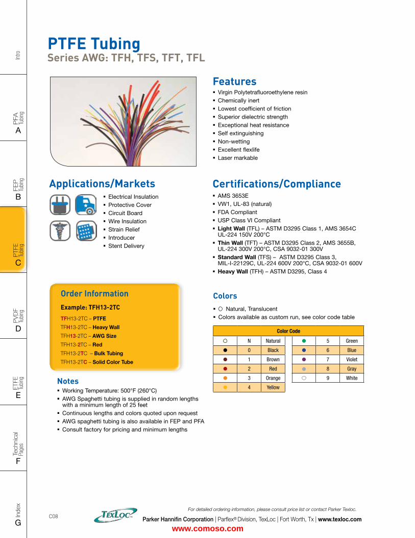
Intro
PFA
Tu
bing
A
FEP
Tu
bing
B
PVD
F
Tubi
ng
D
PTFE
Tu
bing
C
Index
G
Tech
nica
l Pa
ges
F
ETFE
Tu
bing
E
Parker Hannifin Corporation | Parflex® Division, TexLoc | Fort Worth, Tx | www.texloc.com
For detailed ordering information, please consult price list or contact Parker Texloc.
C08
Colors � Natural, Translucent � Colors available as custom run, see color code table
Order InformationExample: TFH13-2TC
TFH13-2TC – PTFE
TFH13-2TC – Heavy Wall
TFH13-2TC – AWG Size
TFH13-2TC – Red
TFH13-2TC – Bulk Tubing
TFH13-2TC – Solid Color Tube
PTFE Tubing Series AWG: TFH, TFS, TFT, TFL
Features � Virgin Polytetrafluoroethylene resin � Chemically inert � Lowest coefficient of friction � Superior dielectric strength � Exceptional heat resistance � Self extinguishing � Non-wetting � Excellent flexlife � Laser markable
Certifications/Compliance � AMS 3653E � VW1, UL-83 (natural) � FDA Compliant � USP Class VI Compliant � Light Wall (TFL) – ASTM D3295 Class 1, AMS 3654C UL-224 150V 200°C
� Thin Wall (TFT) – ASTM D3295 Class 2, AMS 3655B, UL-224 300V 200°C, CSA 9032-01 300V
� Standard Wall (TFS) – ASTM D3295 Class 3, MIL-I-22129C, UL-224 600V 200°C, CSA 9032-01 600V
� Heavy Wall (TFH) – ASTM D3295, Class 4
Color Code
N Natural 5 Green
0 Black 6 Blue
1 Brown 7 Violet
2 Red 8 Gray
3 Orange 9 White
4 YellowNotes � Working Temperature: 500°F (260°C) � AWG Spaghetti tubing is supplied in random lengths with a minimum length of 25 feet
� Continuous lengths and colors quoted upon request � AWG spaghetti tubing is also available in FEP and PFA � Consult factory for pricing and minimum lengths
Applications/Markets � Electrical Insulation � Protective Cover � Circuit Board � Wire Insulation � Strain Relief � Introducer � Stent Delivery
www.comoso.com
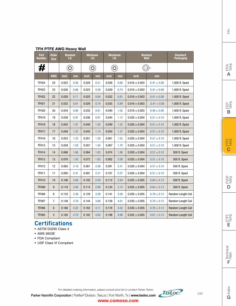
FLAT SIZE – 8.5" X 11" (11 x 17 spreads to be separated during final gather)CUT SIZE – 8.5" X 11"BLEED SIZE – 8.75” X 11.25”FINISHINGS – Drill holes
Intro
PFA
Tu
bing
A
FEP
Tu
bing
B
PVD
F
Tubi
ng
D
PTFE
Tu
bing
C
Index
G
Tech
nica
l Pa
ges
F
ETFE
Tu
bing
E
Parker Hannifin Corporation | Parflex® Division, TexLoc | Fort Worth, Tx | www.texloc.com
For detailed ordering information, please consult price list or contact Parker Texloc.
C09
TFH PTFE AWG Heavy Wall
Part Number
Order Size
Nominal I.D.
Minimum I.D.
Maximum I.D.
Nominal Wall
Standard Packaging
AWG inch mm inch mm inch mm inch mm
TFH24 24 0.022 0.56 0.020 0.51 0.026 0.66 0.016 ± 0.003 0.41 ± 0.08 1,000 ft. Spool
TFH23 23 0.026 0.66 0.023 0.58 0.029 0.74 0.016 ± 0.003 0.41 ± 0.08 1,000 ft. Spool
TFH22 22 0.028 0.71 0.025 0.64 0.032 0.81 0.016 ± 0.003 0.41 ± 0.08 1,000 ft. Spool
TFH21 21 0.032 0.81 0.029 0.74 0.035 0.89 0.016 ± 0.003 .0.41 ± 0.08 1,000 ft. Spool
TFH20 20 0.034 0.86 0.032 0.81 0.040 1.02 0.018 ± 0.003 0.46 ± 0.08 1,000 ft. Spool
TFH19 19 0.038 0.97 0.036 0.91 0.044 1.12 0.020 ± 0.004 0.51 ± 0.10 1,000 ft. Spool
TFH18 18 0.042 1.07 0.040 1.02 0.049 1.25 0.020 ± 0.004 0.51 ± 0.10 1,000 ft. Spool
TFH17 17 0.048 1.22 0.045 1.14 0.054 1.37 0.020 ± 0.004 0.51 ± 0.10 1,000 ft. Spool
TFH16 16 0.053 1.35 0.051 1.30 0.061 1.55 0.020 ± 0.004 0.51 ± 0.10 1,000 ft. Spool
TFH15 15 0.059 1.50 0.057 1.45 0.067 1.70 0.020 ± 0.004 0.51 ± 0.10 1,000 ft. Spool
TFH14 14 0.066 1.68 0.064 1.63 0.074 1.88 0.020 ± 0.004 0.51 ± 0.10 500 ft. Spool
TFH13 13 0.076 1.93 0.072 1.83 0.082 2.08 0.020 ± 0.004 0.51 ± 0.10 500 ft. Spool
TFH12 12 0.085 2.16 0.081 2.06 0.091 2.31 0.020 ± 0.004 0.51 ± 0.10 500 ft. Spool
TFH11 11 0.095 2.41 0.091 2.31 0.101 2.57 0.020 ± 0.004 0.51 ± 0.10 500 ft. Spool
TFH10 10 0.106 2.69 0.102 2.59 0.112 2.84 0.025 ± 0.005 0.64 ± 0.13 500 ft. Spool
TFH09 9 0.118 3.00 0.114 2.90 0.124 3.15 0.025 ± 0.005 0.64 ± 0.13 500 ft. Spool
TFH08 8 0.133 3.38 0.129 3.28 0.141 3.58 0.030 ± 0.005 0.76 ± 0.13 Random Length Coil
TFH07 7 0.148 3.76 0.144 3.66 0.158 4.01 0.030 ± 0.005 0.76 ± 0.13 Random Length Coil
TFH06 6 0.166 4.22 0.162 4.11 0.178 4.52 0.030 ± 0.005 0.76 ± 0.13 Random Length Coil
TFH05 5 0.185 4.70 0.182 4.62 0.196 4.98 0.032 ± 0.005 0.81 ± 0.13 Random Length Coil
Certifications � ASTM D3295 Class 4 � AMS 3653E � FDA Compliant � USP Class VI Compliant
www.comoso.com
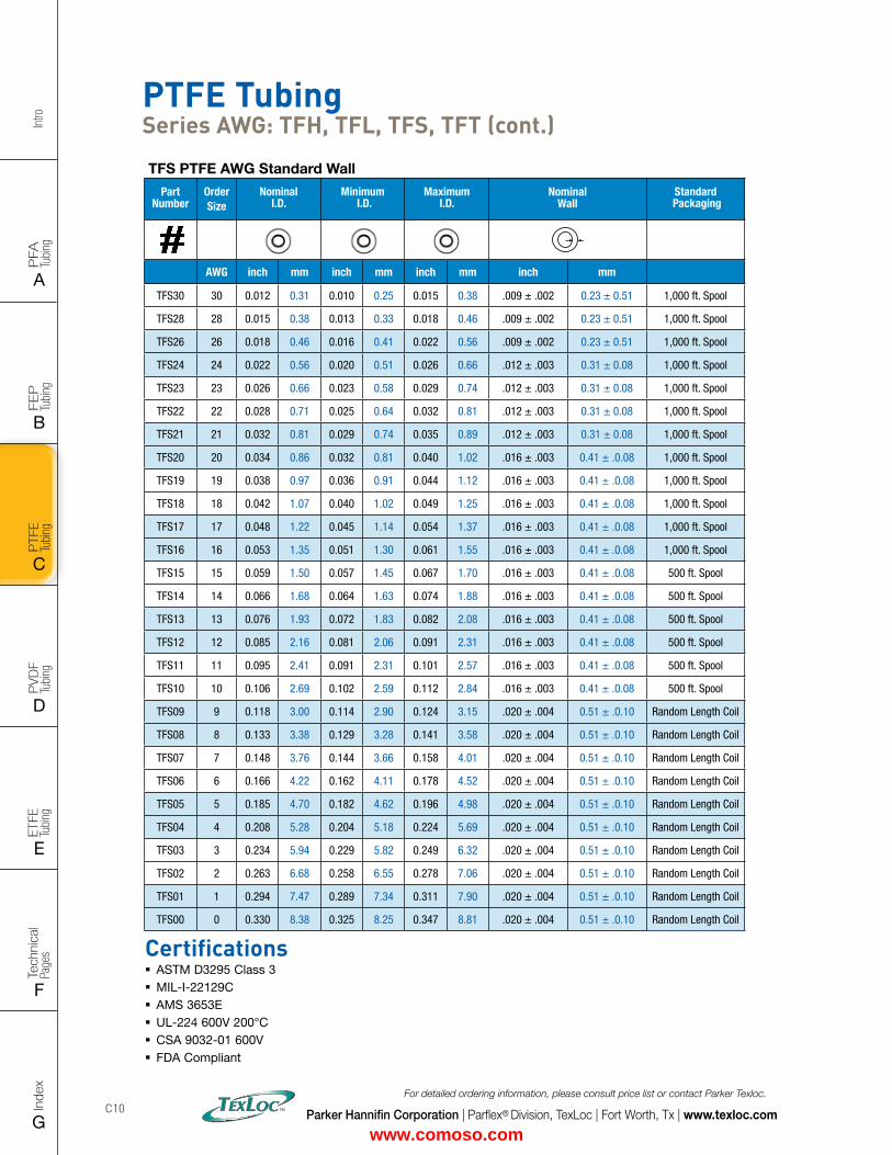
Intro
PFA
Tu
bing
A
FEP
Tu
bing
B
PVD
F
Tubi
ng
D
PTFE
Tu
bing
C
Index
G
Tech
nica
l Pa
ges
F
ETFE
Tu
bing
E
Parker Hannifin Corporation | Parflex® Division, TexLoc | Fort Worth, Tx | www.texloc.com
For detailed ordering information, please consult price list or contact Parker Texloc.
C10
TFS PTFE AWG Standard Wall
Part Number
Order Size
Nominal I.D.
Minimum I.D.
Maximum I.D.
Nominal Wall
Standard Packaging
AWG inch mm inch mm inch mm inch mm
TFS30 30 0.012 0.31 0.010 0.25 0.015 0.38 .009 ± .002 0.23 ± 0.51 1,000 ft. Spool
TFS28 28 0.015 0.38 0.013 0.33 0.018 0.46 .009 ± .002 0.23 ± 0.51 1,000 ft. Spool
TFS26 26 0.018 0.46 0.016 0.41 0.022 0.56 .009 ± .002 0.23 ± 0.51 1,000 ft. Spool
TFS24 24 0.022 0.56 0.020 0.51 0.026 0.66 .012 ± .003 0.31 ± 0.08 1,000 ft. Spool
TFS23 23 0.026 0.66 0.023 0.58 0.029 0.74 .012 ± .003 0.31 ± 0.08 1,000 ft. Spool
TFS22 22 0.028 0.71 0.025 0.64 0.032 0.81 .012 ± .003 0.31 ± 0.08 1,000 ft. Spool
TFS21 21 0.032 0.81 0.029 0.74 0.035 0.89 .012 ± .003 0.31 ± 0.08 1,000 ft. Spool
TFS20 20 0.034 0.86 0.032 0.81 0.040 1.02 .016 ± .003 0.41 ± .0.08 1,000 ft. Spool
TFS19 19 0.038 0.97 0.036 0.91 0.044 1.12 .016 ± .003 0.41 ± .0.08 1,000 ft. Spool
TFS18 18 0.042 1.07 0.040 1.02 0.049 1.25 .016 ± .003 0.41 ± .0.08 1,000 ft. Spool
TFS17 17 0.048 1.22 0.045 1.14 0.054 1.37 .016 ± .003 0.41 ± .0.08 1,000 ft. Spool
TFS16 16 0.053 1.35 0.051 1.30 0.061 1.55 .016 ± .003 0.41 ± .0.08 1,000 ft. Spool
TFS15 15 0.059 1.50 0.057 1.45 0.067 1.70 .016 ± .003 0.41 ± .0.08 500 ft. Spool
TFS14 14 0.066 1.68 0.064 1.63 0.074 1.88 .016 ± .003 0.41 ± .0.08 500 ft. Spool
TFS13 13 0.076 1.93 0.072 1.83 0.082 2.08 .016 ± .003 0.41 ± .0.08 500 ft. Spool
TFS12 12 0.085 2.16 0.081 2.06 0.091 2.31 .016 ± .003 0.41 ± .0.08 500 ft. Spool
TFS11 11 0.095 2.41 0.091 2.31 0.101 2.57 .016 ± .003 0.41 ± .0.08 500 ft. Spool
TFS10 10 0.106 2.69 0.102 2.59 0.112 2.84 .016 ± .003 0.41 ± .0.08 500 ft. Spool
TFS09 9 0.118 3.00 0.114 2.90 0.124 3.15 .020 ± .004 0.51 ± .0.10 Random Length Coil
TFS08 8 0.133 3.38 0.129 3.28 0.141 3.58 .020 ± .004 0.51 ± .0.10 Random Length Coil
TFS07 7 0.148 3.76 0.144 3.66 0.158 4.01 .020 ± .004 0.51 ± .0.10 Random Length Coil
TFS06 6 0.166 4.22 0.162 4.11 0.178 4.52 .020 ± .004 0.51 ± .0.10 Random Length Coil
TFS05 5 0.185 4.70 0.182 4.62 0.196 4.98 .020 ± .004 0.51 ± .0.10 Random Length Coil
TFS04 4 0.208 5.28 0.204 5.18 0.224 5.69 .020 ± .004 0.51 ± .0.10 Random Length Coil
TFS03 3 0.234 5.94 0.229 5.82 0.249 6.32 .020 ± .004 0.51 ± .0.10 Random Length Coil
TFS02 2 0.263 6.68 0.258 6.55 0.278 7.06 .020 ± .004 0.51 ± .0.10 Random Length Coil
TFS01 1 0.294 7.47 0.289 7.34 0.311 7.90 .020 ± .004 0.51 ± .0.10 Random Length Coil
TFS00 0 0.330 8.38 0.325 8.25 0.347 8.81 .020 ± .004 0.51 ± .0.10 Random Length Coil
Certifications � ASTM D3295 Class 3 � MIL-I-22129C � AMS 3653E � UL-224 600V 200°C � CSA 9032-01 600V � FDA Compliant
PTFE Tubing Series AWG: TFH, TFL, TFS, TFT (cont.)
www.comoso.com
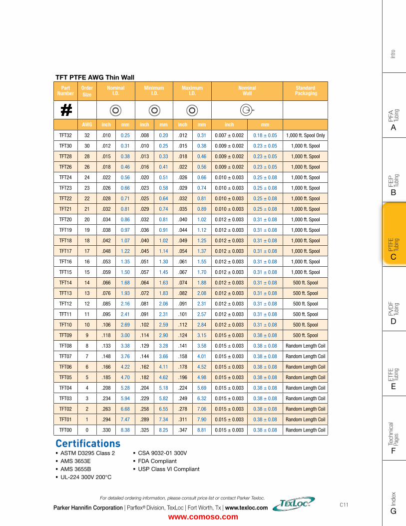
FLAT SIZE – 8.5" X 11" (11 x 17 spreads to be separated during final gather)CUT SIZE – 8.5" X 11"BLEED SIZE – 8.75” X 11.25”FINISHINGS – Drill holes
Intro
PFA
Tu
bing
A
FEP
Tu
bing
B
PVD
F
Tubi
ng
D
PTFE
Tu
bing
C
Index
G
Tech
nica
l Pa
ges
F
ETFE
Tu
bing
E
Parker Hannifin Corporation | Parflex® Division, TexLoc | Fort Worth, Tx | www.texloc.com
For detailed ordering information, please consult price list or contact Parker Texloc.
C11
TFT PTFE AWG Thin Wall
Part Number
Order Size
Nominal I.D.
Minimum I.D.
Maximum I.D.
Nominal Wall
Standard Packaging
AWG inch mm inch mm inch mm inch mm
TFT32 32 .010 0.25 .008 0.20 .012 0.31 0.007 ± 0.002 0.18 ± 0.05 1,000 ft. Spool Only
TFT30 30 .012 0.31 .010 0.25 .015 0.38 0.009 ± 0.002 0.23 ± 0.05 1,000 ft. Spool
TFT28 28 .015 0.38 .013 0.33 .018 0.46 0.009 ± 0.002 0.23 ± 0.05 1,000 ft. Spool
TFT26 26 .018 0.46 .016 0.41 .022 0.56 0.009 ± 0.002 0.23 ± 0.05 1,000 ft. Spool
TFT24 24 .022 0.56 .020 0.51 .026 0.66 0.010 ± 0.003 0.25 ± 0.08 1,000 ft. Spool
TFT23 23 .026 0.66 .023 0.58 .029 0.74 0.010 ± 0.003 0.25 ± 0.08 1,000 ft. Spool
TFT22 22 .028 0.71 .025 0.64 .032 0.81 0.010 ± 0.003 0.25 ± 0.08 1,000 ft. Spool
TFT21 21 .032 0.81 .029 0.74 .035 0.89 0.010 ± 0.003 0.25 ± 0.08 1,000 ft. Spool
TFT20 20 .034 0.86 .032 0.81 .040 1.02 0.012 ± 0.003 0.31 ± 0.08 1,000 ft. Spool
TFT19 19 .038 0.97 .036 0.91 .044 1.12 0.012 ± 0.003 0.31 ± 0.08 1,000 ft. Spool
TFT18 18 .042 1.07 .040 1.02 .049 1.25 0.012 ± 0.003 0.31 ± 0.08 1,000 ft. Spool
TFT17 17 .048 1.22 .045 1.14 .054 1.37 0.012 ± 0.003 0.31 ± 0.08 1,000 ft. Spool
TFT16 16 .053 1.35 .051 1.30 .061 1.55 0.012 ± 0.003 0.31 ± 0.08 1,000 ft. Spool
TFT15 15 .059 1.50 .057 1.45 .067 1.70 0.012 ± 0.003 0.31 ± 0.08 1,000 ft. Spool
TFT14 14 .066 1.68 .064 1.63 .074 1.88 0.012 ± 0.003 0.31 ± 0.08 500 ft. Spool
TFT13 13 .076 1.93 .072 1.83 .082 2.08 0.012 ± 0.003 0.31 ± 0.08 500 ft. Spool
TFT12 12 .085 2.16 .081 2.06 .091 2.31 0.012 ± 0.003 0.31 ± 0.08 500 ft. Spool
TFT11 11 .095 2.41 .091 2.31 .101 2.57 0.012 ± 0.003 0.31 ± 0.08 500 ft. Spool
TFT10 10 .106 2.69 .102 2.59 .112 2.84 0.012 ± 0.003 0.31 ± 0.08 500 ft. Spool
TFT09 9 .118 3.00 .114 2.90 .124 3.15 0.015 ± 0.003 0.38 ± 0.08 500 ft. Spool
TFT08 8 .133 3.38 .129 3.28 .141 3.58 0.015 ± 0.003 0.38 ± 0.08 Random Length Coil
TFT07 7 .148 3.76 .144 3.66 .158 4.01 0.015 ± 0.003 0.38 ± 0.08 Random Length Coil
TFT06 6 .166 4.22 .162 4.11 .178 4.52 0.015 ± 0.003 0.38 ± 0.08 Random Length Coil
TFT05 5 .185 4.70 .182 4.62 .196 4.98 0.015 ± 0.003 0.38 ± 0.08 Random Length Coil
TFT04 4 .208 5.28 .204 5.18 .224 5.69 0.015 ± 0.003 0.38 ± 0.08 Random Length Coil
TFT03 3 .234 5.94 .229 5.82 .249 6.32 0.015 ± 0.003 0.38 ± 0.08 Random Length Coil
TFT02 2 .263 6.68 .258 6.55 .278 7.06 0.015 ± 0.003 0.38 ± 0.08 Random Length Coil
TFT01 1 .294 7.47 .289 7.34 .311 7.90 0.015 ± 0.003 0.38 ± 0.08 Random Length Coil
TFT00 0 .330 8.38 .325 8.25 .347 8.81 0.015 ± 0.003 0.38 ± 0.08 Random Length Coil
Certifications � ASTM D3295 Class 2 � AMS 3653E � AMS 3655B � UL-224 300V 200°C
� CSA 9032-01 300V � FDA Compliant � USP Class VI Compliant
www.comoso.com
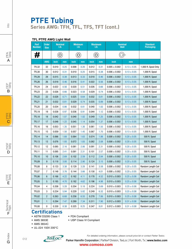
Intro
PFA
Tu
bing
A
FEP
Tu
bing
B
PVD
F
Tubi
ng
D
PTFE
Tu
bing
C
Index
G
Tech
nica
l Pa
ges
F
ETFE
Tu
bing
E
Parker Hannifin Corporation | Parflex® Division, TexLoc | Fort Worth, Tx | www.texloc.com
For detailed ordering information, please consult price list or contact Parker Texloc.
C12
TFL PTFE AWG Light Wall
Part Number
Order Size
Nominal I.D.
Minimum I.D.
Maximum I.D.
Nominal Wall
Standard Packaging
AWG inch mm inch mm inch mm inch mm
TFL32 32 0.010 0.25 0.008 0.20 0.012 0.31 0.005 ± 0.002 0.13 ± 0.05 1,000 ft. Spool Only
TFL30 30 0.012 0.31 0.010 0.25 0.015 0.38 0.006 ± 0.002 0.13 ± 0.05 1,000 ft. Spool
TFL28 28 0.015 0.38 0.013 0.33 0.018 0.46 0.006 ± 0.002 0.13 ± 0.05 1,000 ft. Spool
TFL26 26 0.018 0.46 0.016 0.41 0.022 0.56 0.006 ± 0.002 0.13 ± 0.05 1,000 ft. Spool
TFL24 24 0.022 0.56 0.020 0.51 0.026 0.66 0.006 ± 0.002 0.13 ± 0.05 1,000 ft. Spool
TFL23 23 0.026 0.66 0.023 0.58 0.029 0.74 0.006 ± 0.002 0.13 ± 0.05 1,000 ft. Spool
TFL22 22 0.028 0.71 0.025 0.64 0.032 0.81 0.006 ± 0.002 0.13 ± 0.05 1,000 ft. Spool
TFL21 21 0.032 0.81 0.029 0.74 0.035 0.89 0.006 ± 0.002 0.13 ± 0.05 1,000 ft. Spool
TFL20 20 0.034 0.86 0.032 0.81 0.040 1.02 0.006 ± 0.002 0.13 ± 0.05 1,000 ft. Spool
TFL19 19 0.038 0.97 0.036 0.91 0.044 1.12 0.006 ± 0.002 0.13 ± 0.05 1,000 ft. Spool
TFL18 18 0.042 1.07 0.040 1.02 0.049 1.25 0.006 ± 0.002 0.13 ± 0.05 1,000 ft. Spool
TFL17 17 0.048 1.22 0.045 1.14 0.054 1.37 0.006 ± 0.002 0.13 ± 0.05 1,000 ft. Spool
TFL16 16 0.053 1.35 0.051 1.30 0.061 1.55 0.006 ± 0.002 0.13 ± 0.05 1,000 ft. Spool
TFL15 15 0.059 1.50 0.057 1.45 0.067 1.70 0.006 ± 0.002 0.13 ± 0.05 1,000 ft. Spool
TFL14 14 0.066 1.68 0.064 1.63 0.074 1.88 0.008 ± 0.002 0.20 ± 0.05 500 ft. Spool
TFL13 13 0.076 1.93 0.072 1.83 0.082 2.08 0.008 ± 0.002 0.20 ± 0.05 500 ft. Spool
TFL12 12 0.085 2.16 0.081 2.06 0.091 2.31 0.008 ± 0.002 0.20 ± 0.05 500 ft. Spool
TFL11 11 0.095 2.41 0.091 2.31 0.101 2.57 0.008 ± 0.002 0.20 ± 0.05 500 ft. Spool
TFL10 10 0.106 2.69 0.102 2.59 0.112 2.84 0.008 ± 0.002 0.20 ± 0.05 500 ft. Spool
TFL09 9 0.118 3.00 0.114 2.90 0.124 3.15 0.008 ± 0.002 0.20 ± 0.05 500 ft. Spool
TFL08 8 0.133 3.38 0.129 3.28 0.141 3.58 0.008 ± 0.002 0.20 ± 0.05 Random Length Coil
TFL07 7 0.148 3.76 0.144 3.66 0.158 4.01 0.008 ± 0.002 0.20 ± 0.05 Random Length Coil
TFL06 6 0.166 4.22 0.162 4.11 0.178 4.52 0.010 ± 0.003 0.25 ± 0.08 Random Length Coil
TFL05 5 0.185 4.70 0.182 4.62 0.196 4.98 0.010 ± 0.003 0.25 ± 0.08 Random Length Coil
TFL04 4 0.208 5.28 0.204 5.18 0.224 5.69 0.010 ± 0.003 0.25 ± 0.08 Random Length Coil
TFL03 3 0.234 5.94 0.229 5.82 0.249 6.32 0.010 ± 0.003 0.25 ± 0.08 Random Length Coil
TFL02 2 0.263 6.68 0.258 6.55 0.278 7.06 0.010 ± 0.003 0.25 ± 0.08 Random Length Coil
TFL01 1 0.294 7.47 0.289 7.34 0.311 7.90 0.012 ± 0.003 0.31 ± 0.08 Random Length Coil
TFL00 0 0.330 8.38 0.325 8.25 0.347 8.81 0.012 ± 0.003 0.31 ± 0.08 Random Length Coil
PTFE Tubing Series AWG: TFH, TFL, TFS, TFT (cont.)
Certifications � ASTM D3295 Class 1 � AMS 3653E � AMS 3654C � UL-224 150V 200°C
� FDA Compliant � USP Class VI Compliant
www.comoso.com
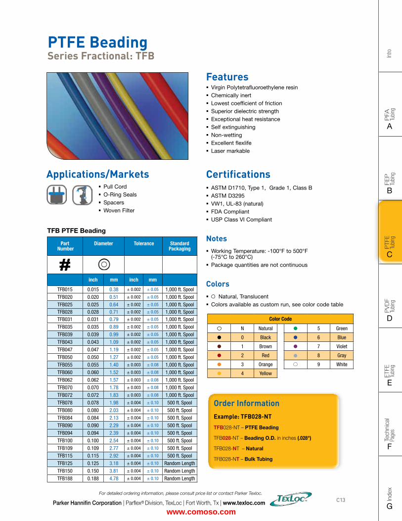
FLAT SIZE – 8.5" X 11" (11 x 17 spreads to be separated during final gather)CUT SIZE – 8.5" X 11"BLEED SIZE – 8.75” X 11.25”FINISHINGS – Drill holes
Intro
PFA
Tu
bing
A
FEP
Tu
bing
B
PVD
F
Tubi
ng
D
PTFE
Tu
bing
C
Index
G
Tech
nica
l Pa
ges
F
ETFE
Tu
bing
E
Parker Hannifin Corporation | Parflex® Division, TexLoc | Fort Worth, Tx | www.texloc.com
For detailed ordering information, please consult price list or contact Parker Texloc.
C13
PTFE Beading Series Fractional: TFB
Features � Virgin Polytetrafluoroethylene resin � Chemically inert � Lowest coefficient of friction � Superior dielectric strength � Exceptional heat resistance � Self extinguishing � Non-wetting � Excellent flexlife � Laser markable
Certifications � ASTM D1710, Type 1, Grade 1, Class B � ASTM D3295 � VW1, UL-83 (natural) � FDA Compliant � USP Class VI Compliant
Notes � Working Temperature: -100°F to 500°F (-75°C to 260°C)
� Package quantities are not continuous
Colors � Natural, Translucent � Colors available as custom run, see color code table
TFB PTFE Beading
Part Number
Diameter Tolerance StandardPackaging
inch mm inch mm
TFB015 0.015 0.38 ± 0.002 ± 0.05 1,000 ft. Spool
TFB020 0.020 0.51 ± 0.002 ± 0.05 1,000 ft. Spool
TFB025 0.025 0.64 ± 0.002 ± 0.05 1,000 ft. SpoolTFB028 0.028 0.71 ± 0.002 ± 0.05 1,000 ft. SpoolTFB031 0.031 0.79 ± 0.002 ± 0.05 1,000 ft. Spool
TFB035 0.035 0.89 ± 0.002 ± 0.05 1,000 ft. Spool
TFB039 0.039 0.99 ± 0.002 ± 0.05 1,000 ft. Spool
TFB043 0.043 1.09 ± 0.002 ± 0.05 1,000 ft. Spool
TFB047 0.047 1.19 ± 0.002 ± 0.05 1,000 ft. Spool
TFB050 0.050 1.27 ± 0.002 ± 0.05 1,000 ft. Spool
TFB055 0.055 1.40 ± 0.003 ± 0.08 1,000 ft. Spool
TFB060 0.060 1.52 ± 0.003 ± 0.08 1,000 ft. Spool
TFB062 0.062 1.57 ± 0.003 ± 0.08 1,000 ft. Spool
TFB070 0.070 1.78 ± 0.003 ± 0.08 1,000 ft. Spool
TFB072 0.072 1.83 ± 0.003 ± 0.08 1,000 ft. Spool
TFB078 0.078 1.98 ± 0.004 ± 0.10 500 ft. Spool
TFB080 0.080 2.03 ± 0.004 ± 0.10 500 ft. Spool
TFB084 0.084 2.13 ± 0.004 ± 0.10 500 ft. Spool
TFB090 0.090 2.29 ± 0.004 ± 0.10 500 ft. Spool
TFB094 0.094 2.39 ± 0.004 ± 0.10 500 ft. Spool
TFB100 0.100 2.54 ± 0.004 ± 0.10 500 ft. Spool
TFB109 0.109 2.77 ± 0.004 ± 0.10 500 ft. Spool
TFB115 0.115 2.92 ± 0.004 ± 0.10 500 ft. Spool
TFB125 0.125 3.18 ± 0.004 ± 0.10 Random Length
TFB150 0.150 3.81 ± 0.004 ± 0.10 Random Length
TFB188 0.188 4.78 ± 0.004 ± 0.10 Random Length
Order InformationExample: TFB028-NT
TFB028-NT – PTFE Beading
TFB028-NT – Beading O.D. in inches (.028")
TFB028-NT – Natural
TFB028-NT – Bulk Tubing
Color Code
N Natural 5 Green
0 Black 6 Blue
1 Brown 7 Violet
2 Red 8 Gray
3 Orange 9 White
4 Yellow
Applications/Markets � Pull Cord � O-Ring Seals � Spacers � Woven Filter
www.comoso.com
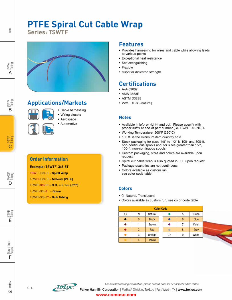
Intro
PFA
Tu
bing
A
FEP
Tu
bing
B
PVD
F
Tubi
ng
D
PTFE
Tu
bing
C
Index
G
Tech
nica
l Pa
ges
F
ETFE
Tu
bing
E
Parker Hannifin Corporation | Parflex® Division, TexLoc | Fort Worth, Tx | www.texloc.com
For detailed ordering information, please consult price list or contact Parker Texloc.
C14
PTFE Spiral Cut Cable Wrap Series: TSWTF
Features � Provides harnessing for wires and cable while allowing leads at various points
� Exceptional heat resistance � Self extinguishing � Flexible � Superior dielectric strength
Certifications � A-A-59602 � AMS 3653E � ASTM D3295 � VW1, UL-83 (natural)
Notes � Available in left- or right-hand cut. Please specify with proper suffix at end of part number (i.e. TSWTF-18-NT-R)
� Working Temperature: 500°F (260°C) � 100 ft. is the minimum item quantity sold � Stock packaging for sizes 1/8" to 1/2" is 100- and 500-ft. non-continuous spools and, for sizes greater than 1/2", 100-ft. non-continuous spools
� Custom packaging, sizes and colors are available upon request
� Spiral cut cable wrap is also quoted in FEP upon request � Package quantities are not continuous � Colors available as custom run, see color code table
Order InformationExample: TSWTF-3/8-5T
TSWTF-3/8-5T – Spiral Wrap
TSWTF-3/8-5T – Material (PTFE)
TSWTF-3/8-5T – O.D. in inches (.375")
TSWTF-3/8-5T – Green
TSWTF-3/8-5T – Bulk Tubing
Colors � Natural, Translucent � Colors available as custom run, see color code table
Color Code
N Natural 5 Green
0 Black 6 Blue
1 Brown 7 Violet
2 Red 8 Gray
3 Orange 9 White
4 Yellow
Applications/Markets � Cable harnessing � Wiring closets � Aerospace � Automotive
www.comoso.com
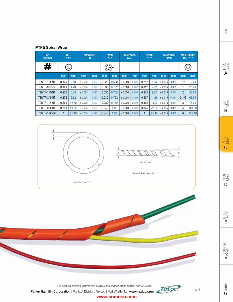
FLAT SIZE – 8.5" X 11" (11 x 17 spreads to be separated during final gather)CUT SIZE – 8.5" X 11"BLEED SIZE – 8.75” X 11.25”FINISHINGS – Drill holes
Intro
PFA
Tu
bing
A
FEP
Tu
bing
B
PVD
F
Tubi
ng
D
PTFE
Tu
bing
C
Index
G
Tech
nica
l Pa
ges
F
ETFE
Tu
bing
E
Parker Hannifin Corporation | Parflex® Division, TexLoc | Fort Worth, Tx | www.texloc.com
For detailed ordering information, please consult price list or contact Parker Texloc.
C15
Order InformationExample: 101-0188062-0TC-100
101-0188062-0TC-100 – PTFE
101-0188062-0TC-100 – Tube O.D. in inches (3/16")
101-0188062-0TC-100 – Tube Wall Thickness in inches (.062")
101-0188062-0TC-100 – Black
101-0188062-0TC-100 – Bulk Tubing
101-0188062-0TC-100 – Solid Color Tube
101-0188062-0TC-100 – Package Quantity in feet (100')
PTFE Spiral Wrap
Part Number
O.D. "A"
toleranceO.D.
Wall "B"
toleranceWall
Pitch "D"
tolerancePitch
Max Bundle O.D. “C”
inch mm inch mm inch mm inch mm inch mm inch mm inch mm
TSWTF-1/8-NT 0.125 3.18 ± 0.005 0.127 0.020 0.508 ± 0.008 0.203 0.212 5.38 ± 0.015 0.381 1/2 12.70
TSWTF-3/16-NT 0.188 4.78 ± 0.005 0.127 0.030 0.762 ± 0.008 0.203 0.312 7.92 ± 0.015 0.381 1 25.40
TSWTF-1/4-NT 0.250 6.35 ± 0.005 0.127 0.030 0.762 ± 0.008 0.203 0.375 9.52 ± 0.015 0.381 2 50.80
TSWTF-3/8-NT 0.375 9.52 ± 0.005 0.127 0.030 0.762 ± 0.008 0.203 0.437 11.10 ± 0.015 0.381 2-1/2 63.50
TSWTF-1/2-NT 0.500 12.70 ± 0.005 0.127 0.030 0.762 ± 0.008 0.203 0.562 14.27 ± 0.015 0.381 3 76.20
TSWTF-3/4-NT 0.750 19.05 ± 0.005 0.127 0.040 1.02 ± 0.008 0.203 0.875 22.22 ± 0.015 0.381 4 101.60
TSWTF-1.00-NT 1 25.40 ± 0.005 0.127 0.040 1.02 ± 0.008 0.203 1 25.40 ± 0.015 0.381 6 152.40
www.comoso.com
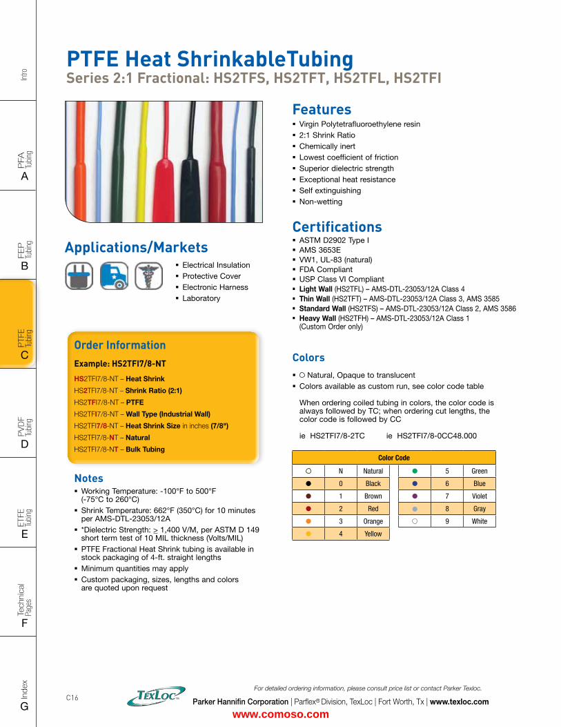
Intro
PFA
Tu
bing
A
FEP
Tu
bing
B
PVD
F
Tubi
ng
D
PTFE
Tu
bing
C
Index
G
Tech
nica
l Pa
ges
F
ETFE
Tu
bing
E
Parker Hannifin Corporation | Parflex® Division, TexLoc | Fort Worth, Tx | www.texloc.com
For detailed ordering information, please consult price list or contact Parker Texloc.
C16
PTFE Heat ShrinkableTubing Series 2:1 Fractional: HS2TFS, HS2TFT, HS2TFL, HS2TFI
Features � Virgin Polytetrafluoroethylene resin � 2:1 Shrink Ratio � Chemically inert � Lowest coefficient of friction � Superior dielectric strength � Exceptional heat resistance � Self extinguishing � Non-wetting
Certifications � ASTM D2902 Type I � AMS 3653E � VW1, UL-83 (natural) � FDA Compliant � USP Class VI Compliant � Light Wall (HS2TFL) – AMS-DTL-23053/12A Class 4 � Thin Wall (HS2TFT) – AMS-DTL-23053/12A Class 3, AMS 3585 � Standard Wall (HS2TFS) – AMS-DTL-23053/12A Class 2, AMS 3586 � Heavy Wall (HS2TFH) – AMS-DTL-23053/12A Class 1
(Custom Order only)
Applications/Markets � Electrical Insulation � Protective Cover � Electronic Harness � Laboratory
Notes � Working Temperature: -100°F to 500°F (-75°C to 260°C)
� Shrink Temperature: 662°F (350°C) for 10 minutes per AMS-DTL-23053/12A
� *Dielectric Strength: > 1,400 V/M, per ASTM D 149 short term test of 10 MIL thickness (Volts/MIL)
� PTFE Fractional Heat Shrink tubing is available in stock packaging of 4-ft. straight lengths
� Minimum quantities may apply � Custom packaging, sizes, lengths and colors are quoted upon request
Order InformationExample: HS2TFI7/8-NT
HS2TFI7/8-NT – Heat Shrink
HS2TFI7/8-NT – Shrink Ratio (2:1)
HS2TFI7/8-NT – PTFE
HS2TFI7/8-NT – Wall Type (Industrial Wall)
HS2TFI7/8-NT – Heat Shrink Size in inches (7/8")
HS2TFI7/8-NT – Natural
HS2TFI7/8-NT – Bulk Tubing
Colors � Natural, Opaque to translucent � Colors available as custom run, see color code table When ordering coiled tubing in colors, the color code is always followed by TC; when ordering cut lengths, the color code is followed by CC ie HS2TFI7/8-2TC ie HS2TFI7/8-0CC48.000
Color Code
N Natural 5 Green
0 Black 6 Blue
1 Brown 7 Violet
2 Red 8 Gray
3 Orange 9 White
4 Yellow
www.comoso.com
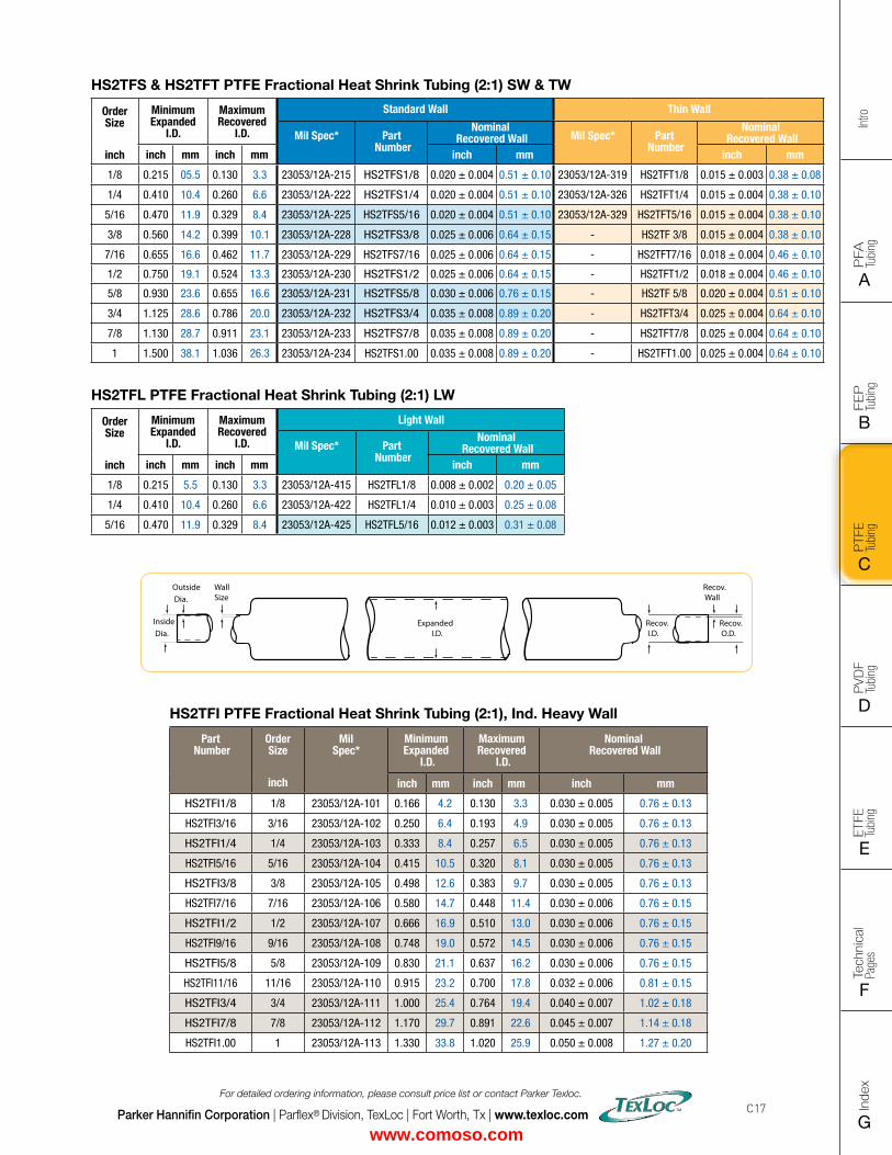
FLAT SIZE – 8.5" X 11" (11 x 17 spreads to be separated during final gather)CUT SIZE – 8.5" X 11"BLEED SIZE – 8.75” X 11.25”FINISHINGS – Drill holes
Intro
PFA
Tu
bing
A
FEP
Tu
bing
B
PVD
F
Tubi
ng
D
PTFE
Tu
bing
C
Index
G
Tech
nica
l Pa
ges
F
ETFE
Tu
bing
E
Parker Hannifin Corporation | Parflex® Division, TexLoc | Fort Worth, Tx | www.texloc.com
For detailed ordering information, please consult price list or contact Parker Texloc.
C17
HS2TFL PTFE Fractional Heat Shrink Tubing (2:1) LW
Order Size
inch
Minimum Expanded
I.D.
Maximum Recovered
I.D.
Light Wall
Mil Spec* Part Number
Nominal Recovered Wall
inch mm inch mm inch mm
1/8 0.215 5.5 0.130 3.3 23053/12A-415 HS2TFL1/8 0.008 ± 0.002 0.20 ± 0.05
1/4 0.410 10.4 0.260 6.6 23053/12A-422 HS2TFL1/4 0.010 ± 0.003 0.25 ± 0.08
5/16 0.470 11.9 0.329 8.4 23053/12A-425 HS2TFL5/16 0.012 ± 0.003 0.31 ± 0.08
HS2TFS & HS2TFT PTFE Fractional Heat Shrink Tubing (2:1) SW & TW
Order Size
inch
Minimum Expanded
I.D.
Maximum Recovered
I.D.
Standard Wall Thin Wall
Mil Spec* Part Number
Nominal Recovered Wall Mil Spec* Part
Number
Nominal Recovered Wall
inch mm inch mm inch mm inch mm
1/8 0.215 05.5 0.130 3.3 23053/12A-215 HS2TFS1/8 0.020 ± 0.004 0.51 ± 0.10 23053/12A-319 HS2TFT1/8 0.015 ± 0.003 0.38 ± 0.08
1/4 0.410 10.4 0.260 6.6 23053/12A-222 HS2TFS1/4 0.020 ± 0.004 0.51 ± 0.10 23053/12A-326 HS2TFT1/4 0.015 ± 0.004 0.38 ± 0.10
5/16 0.470 11.9 0.329 8.4 23053/12A-225 HS2TFS5/16 0.020 ± 0.004 0.51 ± 0.10 23053/12A-329 HS2TFT5/16 0.015 ± 0.004 0.38 ± 0.10
3/8 0.560 14.2 0.399 10.1 23053/12A-228 HS2TFS3/8 0.025 ± 0.006 0.64 ± 0.15 - HS2TF 3/8 0.015 ± 0.004 0.38 ± 0.10
7/16 0.655 16.6 0.462 11.7 23053/12A-229 HS2TFS7/16 0.025 ± 0.006 0.64 ± 0.15 - HS2TFT7/16 0.018 ± 0.004 0.46 ± 0.10
1/2 0.750 19.1 0.524 13.3 23053/12A-230 HS2TFS1/2 0.025 ± 0.006 0.64 ± 0.15 - HS2TFT1/2 0.018 ± 0.004 0.46 ± 0.10
5/8 0.930 23.6 0.655 16.6 23053/12A-231 HS2TFS5/8 0.030 ± 0.006 0.76 ± 0.15 - HS2TF 5/8 0.020 ± 0.004 0.51 ± 0.10
3/4 1.125 28.6 0.786 20.0 23053/12A-232 HS2TFS3/4 0.035 ± 0.008 0.89 ± 0.20 - HS2TFT3/4 0.025 ± 0.004 0.64 ± 0.10
7/8 1.130 28.7 0.911 23.1 23053/12A-233 HS2TFS7/8 0.035 ± 0.008 0.89 ± 0.20 - HS2TFT7/8 0.025 ± 0.004 0.64 ± 0.10
1 1.500 38.1 1.036 26.3 23053/12A-234 HS2TFS1.00 0.035 ± 0.008 0.89 ± 0.20 - HS2TFT1.00 0.025 ± 0.004 0.64 ± 0.10
HS2TFI PTFE Fractional Heat Shrink Tubing (2:1), Ind. Heavy Wall
Part Number
Order Size
inch
Mil Spec*
Minimum Expanded
I.D.
Maximum Recovered
I.D.
Nominal Recovered Wall
inch mm inch mm inch mm
HS2TFI1/8 1/8 23053/12A-101 0.166 4.2 0.130 3.3 0.030 ± 0.005 0.76 ± 0.13
HS2TFI3/16 3/16 23053/12A-102 0.250 6.4 0.193 4.9 0.030 ± 0.005 0.76 ± 0.13
HS2TFI1/4 1/4 23053/12A-103 0.333 8.4 0.257 6.5 0.030 ± 0.005 0.76 ± 0.13
HS2TFI5/16 5/16 23053/12A-104 0.415 10.5 0.320 8.1 0.030 ± 0.005 0.76 ± 0.13
HS2TFI3/8 3/8 23053/12A-105 0.498 12.6 0.383 9.7 0.030 ± 0.005 0.76 ± 0.13
HS2TFI7/16 7/16 23053/12A-106 0.580 14.7 0.448 11.4 0.030 ± 0.006 0.76 ± 0.15
HS2TFI1/2 1/2 23053/12A-107 0.666 16.9 0.510 13.0 0.030 ± 0.006 0.76 ± 0.15
HS2TFI9/16 9/16 23053/12A-108 0.748 19.0 0.572 14.5 0.030 ± 0.006 0.76 ± 0.15
HS2TFI5/8 5/8 23053/12A-109 0.830 21.1 0.637 16.2 0.030 ± 0.006 0.76 ± 0.15
HS2TFI11/16 11/16 23053/12A-110 0.915 23.2 0.700 17.8 0.032 ± 0.006 0.81 ± 0.15
HS2TFI3/4 3/4 23053/12A-111 1.000 25.4 0.764 19.4 0.040 ± 0.007 1.02 ± 0.18
HS2TFI7/8 7/8 23053/12A-112 1.170 29.7 0.891 22.6 0.045 ± 0.007 1.14 ± 0.18
HS2TFI1.00 1 23053/12A-113 1.330 33.8 1.020 25.9 0.050 ± 0.008 1.27 ± 0.20
Recov. Wall
Recov. O.D.
Outside Dia.
Inside Dia.
WallSize
Recov. I.D.
Expanded I.D.
www.comoso.com
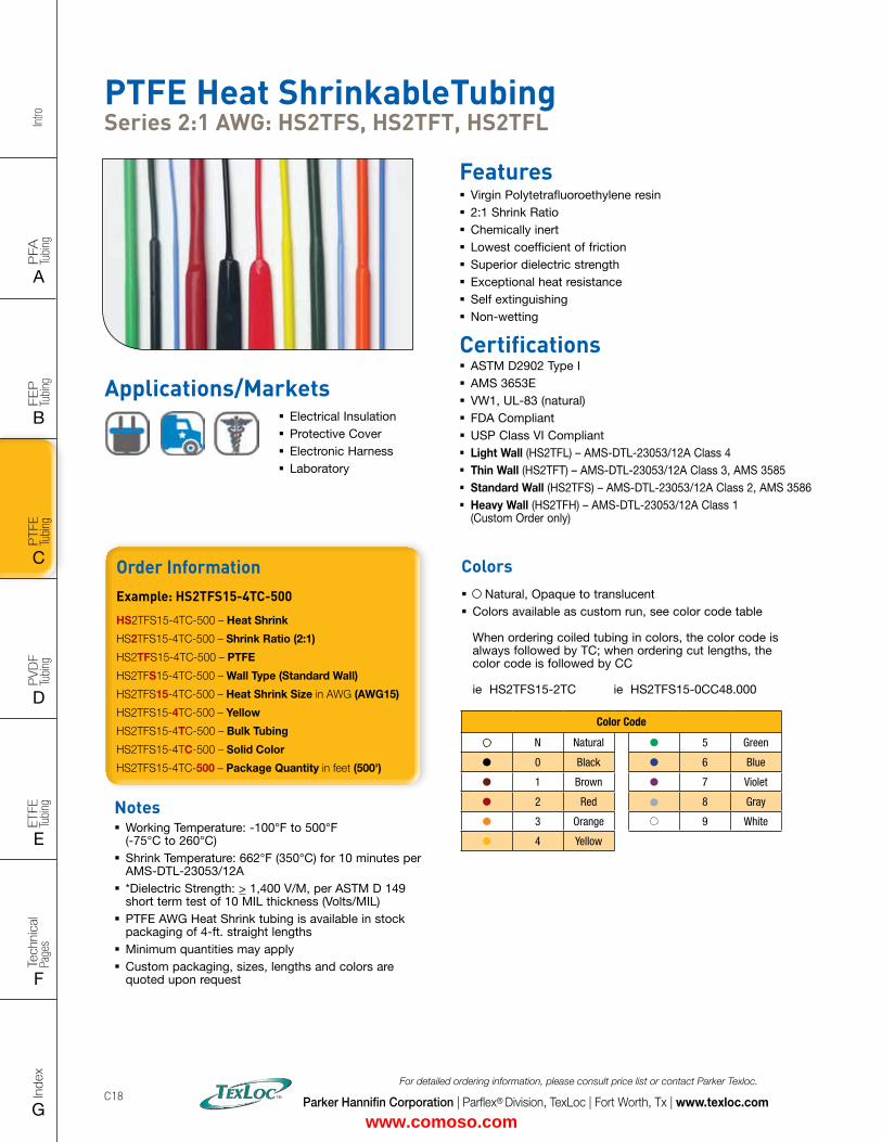
Intro
PFA
Tu
bing
A
FEP
Tu
bing
B
PVD
F
Tubi
ng
D
PTFE
Tu
bing
C
Index
G
Tech
nica
l Pa
ges
F
ETFE
Tu
bing
E
Parker Hannifin Corporation | Parflex® Division, TexLoc | Fort Worth, Tx | www.texloc.com
For detailed ordering information, please consult price list or contact Parker Texloc.
C18
PTFE Heat ShrinkableTubing Series 2:1 AWG: HS2TFS, HS2TFT, HS2TFL
Features � Virgin Polytetrafluoroethylene resin � 2:1 Shrink Ratio � Chemically inert � Lowest coefficient of friction � Superior dielectric strength � Exceptional heat resistance � Self extinguishing � Non-wetting
Certifications � ASTM D2902 Type I � AMS 3653E � VW1, UL-83 (natural) � FDA Compliant � USP Class VI Compliant � Light Wall (HS2TFL) – AMS-DTL-23053/12A Class 4 � Thin Wall (HS2TFT) – AMS-DTL-23053/12A Class 3, AMS 3585 � Standard Wall (HS2TFS) – AMS-DTL-23053/12A Class 2, AMS 3586 � Heavy Wall (HS2TFH) – AMS-DTL-23053/12A Class 1
(Custom Order only)
Order InformationExample: HS2TFS15-4TC-500
HS2TFS15-4TC-500 – Heat Shrink
HS2TFS15-4TC-500 – Shrink Ratio (2:1)
HS2TFS15-4TC-500 – PTFE
HS2TFS15-4TC-500 – Wall Type (Standard Wall)
HS2TFS15-4TC-500 – Heat Shrink Size in AWG (AWG15)
HS2TFS15-4TC-500 – Yellow
HS2TFS15-4TC-500 – Bulk Tubing
HS2TFS15-4TC-500 – Solid Color
HS2TFS15-4TC-500 – Package Quantity in feet (500')
Notes � Working Temperature: -100°F to 500°F (-75°C to 260°C)
� Shrink Temperature: 662°F (350°C) for 10 minutes per AMS-DTL-23053/12A
� *Dielectric Strength: > 1,400 V/M, per ASTM D 149 short term test of 10 MIL thickness (Volts/MIL)
� PTFE AWG Heat Shrink tubing is available in stock packaging of 4-ft. straight lengths
� Minimum quantities may apply � Custom packaging, sizes, lengths and colors are quoted upon request
Colors � Natural, Opaque to translucent � Colors available as custom run, see color code table When ordering coiled tubing in colors, the color code is always followed by TC; when ordering cut lengths, the color code is followed by CC ie HS2TFS15-2TC ie HS2TFS15-0CC48.000
Color Code
N Natural 5 Green
0 Black 6 Blue
1 Brown 7 Violet
2 Red 8 Gray
3 Orange 9 White
4 Yellow
Applications/Markets � Electrical Insulation � Protective Cover � Electronic Harness � Laboratory
www.comoso.com
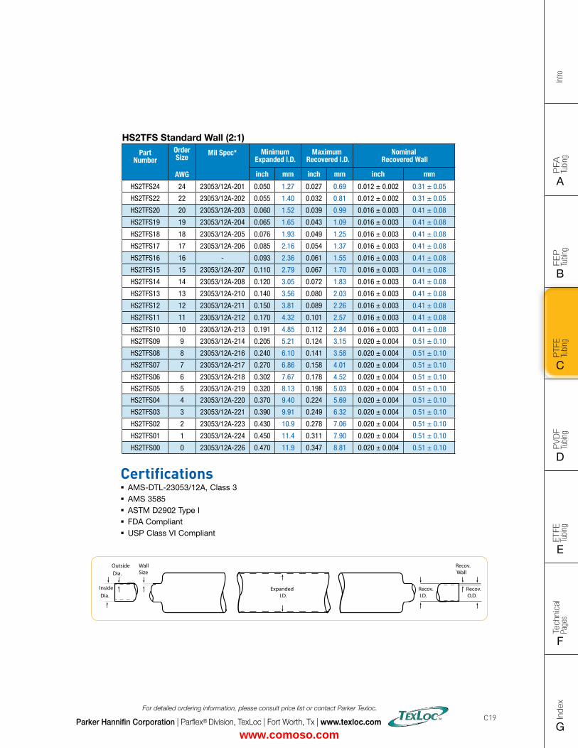
FLAT SIZE – 8.5" X 11" (11 x 17 spreads to be separated during final gather)CUT SIZE – 8.5" X 11"BLEED SIZE – 8.75” X 11.25”FINISHINGS – Drill holes
Intro
PFA
Tu
bing
A
FEP
Tu
bing
B
PVD
F
Tubi
ng
D
PTFE
Tu
bing
C
Index
G
Tech
nica
l Pa
ges
F
ETFE
Tu
bing
E
Parker Hannifin Corporation | Parflex® Division, TexLoc | Fort Worth, Tx | www.texloc.com
For detailed ordering information, please consult price list or contact Parker Texloc.
C19
HS2TFS Standard Wall (2:1)
Part Number
Order Size
AWG
Mil Spec* Minimum Expanded I.D.
Maximum Recovered I.D.
Nominal Recovered Wall
inch mm inch mm inch mm
HS2TFS24 24 23053/12A-201 0.050 1.27 0.027 0.69 0.012 ± 0.002 0.31 ± 0.05
HS2TFS22 22 23053/12A-202 0.055 1.40 0.032 0.81 0.012 ± 0.002 0.31 ± 0.05
HS2TFS20 20 23053/12A-203 0.060 1.52 0.039 0.99 0.016 ± 0.003 0.41 ± 0.08
HS2TFS19 19 23053/12A-204 0.065 1.65 0.043 1.09 0.016 ± 0.003 0.41 ± 0.08
HS2TFS18 18 23053/12A-205 0.076 1.93 0.049 1.25 0.016 ± 0.003 0.41 ± 0.08
HS2TFS17 17 23053/12A-206 0.085 2.16 0.054 1.37 0.016 ± 0.003 0.41 ± 0.08
HS2TFS16 16 - 0.093 2.36 0.061 1.55 0.016 ± 0.003 0.41 ± 0.08
HS2TFS15 15 23053/12A-207 0.110 2.79 0.067 1.70 0.016 ± 0.003 0.41 ± 0.08
HS2TFS14 14 23053/12A-208 0.120 3.05 0.072 1.83 0.016 ± 0.003 0.41 ± 0.08
HS2TFS13 13 23053/12A-210 0.140 3.56 0.080 2.03 0.016 ± 0.003 0.41 ± 0.08
HS2TFS12 12 23053/12A-211 0.150 3.81 0.089 2.26 0.016 ± 0.003 0.41 ± 0.08
HS2TFS11 11 23053/12A-212 0.170 4.32 0.101 2.57 0.016 ± 0.003 0.41 ± 0.08
HS2TFS10 10 23053/12A-213 0.191 4.85 0.112 2.84 0.016 ± 0.003 0.41 ± 0.08
HS2TFS09 9 23053/12A-214 0.205 5.21 0.124 3.15 0.020 ± 0.004 0.51 ± 0.10
HS2TFS08 8 23053/12A-216 0.240 6.10 0.141 3.58 0.020 ± 0.004 0.51 ± 0.10
HS2TFS07 7 23053/12A-217 0.270 6.86 0.158 4.01 0.020 ± 0.004 0.51 ± 0.10
HS2TFS06 6 23053/12A-218 0.302 7.67 0.178 4.52 0.020 ± 0.004 0.51 ± 0.10
HS2TFS05 5 23053/12A-219 0.320 8.13 0.198 5.03 0.020 ± 0.004 0.51 ± 0.10
HS2TFS04 4 23053/12A-220 0.370 9.40 0.224 5.69 0.020 ± 0.004 0.51 ± 0.10
HS2TFS03 3 23053/12A-221 0.390 9.91 0.249 6.32 0.020 ± 0.004 0.51 ± 0.10
HS2TFS02 2 23053/12A-223 0.430 10.9 0.278 7.06 0.020 ± 0.004 0.51 ± 0.10
HS2TFS01 1 23053/12A-224 0.450 11.4 0.311 7.90 0.020 ± 0.004 0.51 ± 0.10
HS2TFS00 0 23053/12A-226 0.470 11.9 0.347 8.81 0.020 ± 0.004 0.51 ± 0.10
Certifications � AMS-DTL-23053/12A, Class 3 � AMS 3585 � ASTM D2902 Type I � FDA Compliant � USP Class VI Compliant
Recov. Wall
Recov. O.D.
Outside Dia.
Inside Dia.
WallSize
Recov. I.D.
Expanded I.D.
www.comoso.com
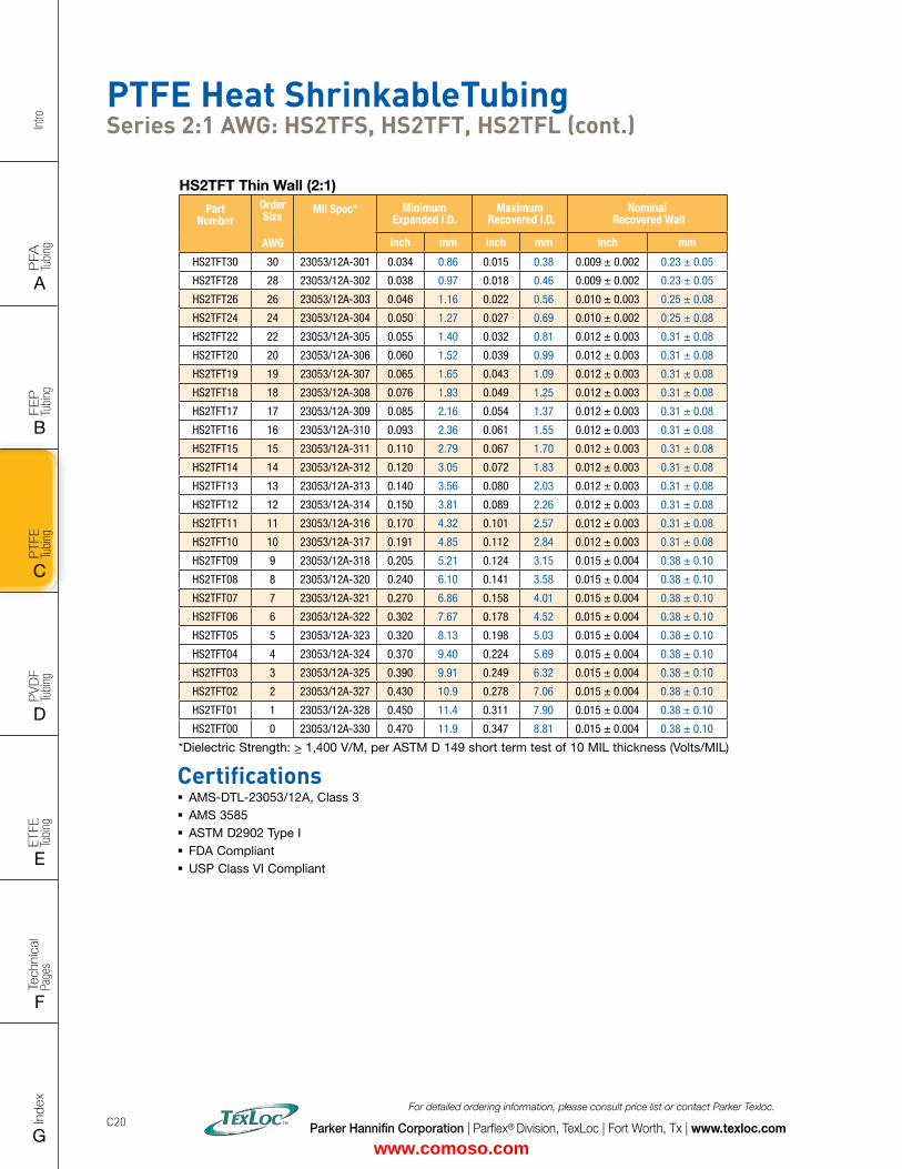
Intro
PFA
Tu
bing
A
FEP
Tu
bing
B
PVD
F
Tubi
ng
D
PTFE
Tu
bing
C
Index
G
Tech
nica
l Pa
ges
F
ETFE
Tu
bing
E
Parker Hannifin Corporation | Parflex® Division, TexLoc | Fort Worth, Tx | www.texloc.com
For detailed ordering information, please consult price list or contact Parker Texloc.
C20
PTFE Heat ShrinkableTubing Series 2:1 AWG: HS2TFS, HS2TFT, HS2TFL (cont.)
HS2TFT Thin Wall (2:1)
Part Number
Order Size
AWG
Mil Spec* Minimum Expanded I.D.
Maximum Recovered I.D.
Nominal Recovered Wall
inch mm inch mm inch mm
HS2TFT30 30 23053/12A-301 0.034 0.86 0.015 0.38 0.009 ± 0.002 0.23 ± 0.05
HS2TFT28 28 23053/12A-302 0.038 0.97 0.018 0.46 0.009 ± 0.002 0.23 ± 0.05
HS2TFT26 26 23053/12A-303 0.046 1.16 0.022 0.56 0.010 ± 0.003 0.25 ± 0.08
HS2TFT24 24 23053/12A-304 0.050 1.27 0.027 0.69 0.010 ± 0.002 0.25 ± 0.08
HS2TFT22 22 23053/12A-305 0.055 1.40 0.032 0.81 0.012 ± 0.003 0.31 ± 0.08
HS2TFT20 20 23053/12A-306 0.060 1.52 0.039 0.99 0.012 ± 0.003 0.31 ± 0.08
HS2TFT19 19 23053/12A-307 0.065 1.65 0.043 1.09 0.012 ± 0.003 0.31 ± 0.08
HS2TFT18 18 23053/12A-308 0.076 1.93 0.049 1.25 0.012 ± 0.003 0.31 ± 0.08
HS2TFT17 17 23053/12A-309 0.085 2.16 0.054 1.37 0.012 ± 0.003 0.31 ± 0.08
HS2TFT16 16 23053/12A-310 0.093 2.36 0.061 1.55 0.012 ± 0.003 0.31 ± 0.08
HS2TFT15 15 23053/12A-311 0.110 2.79 0.067 1.70 0.012 ± 0.003 0.31 ± 0.08
HS2TFT14 14 23053/12A-312 0.120 3.05 0.072 1.83 0.012 ± 0.003 0.31 ± 0.08
HS2TFT13 13 23053/12A-313 0.140 3.56 0.080 2.03 0.012 ± 0.003 0.31 ± 0.08
HS2TFT12 12 23053/12A-314 0.150 3.81 0.089 2.26 0.012 ± 0.003 0.31 ± 0.08
HS2TFT11 11 23053/12A-316 0.170 4.32 0.101 2.57 0.012 ± 0.003 0.31 ± 0.08
HS2TFT10 10 23053/12A-317 0.191 4.85 0.112 2.84 0.012 ± 0.003 0.31 ± 0.08
HS2TFT09 9 23053/12A-318 0.205 5.21 0.124 3.15 0.015 ± 0.004 0.38 ± 0.10
HS2TFT08 8 23053/12A-320 0.240 6.10 0.141 3.58 0.015 ± 0.004 0.38 ± 0.10
HS2TFT07 7 23053/12A-321 0.270 6.86 0.158 4.01 0.015 ± 0.004 0.38 ± 0.10
HS2TFT06 6 23053/12A-322 0.302 7.67 0.178 4.52 0.015 ± 0.004 0.38 ± 0.10
HS2TFT05 5 23053/12A-323 0.320 8.13 0.198 5.03 0.015 ± 0.004 0.38 ± 0.10
HS2TFT04 4 23053/12A-324 0.370 9.40 0.224 5.69 0.015 ± 0.004 0.38 ± 0.10
HS2TFT03 3 23053/12A-325 0.390 9.91 0.249 6.32 0.015 ± 0.004 0.38 ± 0.10
HS2TFT02 2 23053/12A-327 0.430 10.9 0.278 7.06 0.015 ± 0.004 0.38 ± 0.10
HS2TFT01 1 23053/12A-328 0.450 11.4 0.311 7.90 0.015 ± 0.004 0.38 ± 0.10
HS2TFT00 0 23053/12A-330 0.470 11.9 0.347 8.81 0.015 ± 0.004 0.38 ± 0.10
Certifications � AMS-DTL-23053/12A, Class 3 � AMS 3585 � ASTM D2902 Type I � FDA Compliant � USP Class VI Compliant
*Dielectric Strength: > 1,400 V/M, per ASTM D 149 short term test of 10 MIL thickness (Volts/MIL)
www.comoso.com
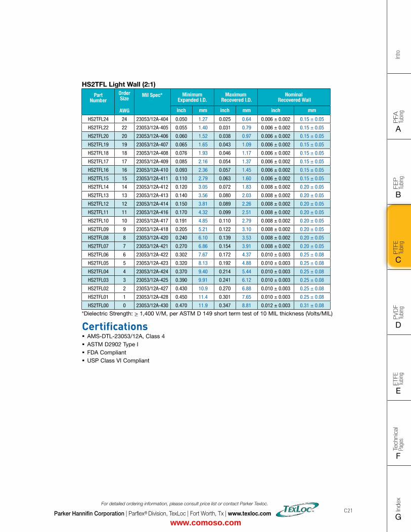
FLAT SIZE – 8.5" X 11" (11 x 17 spreads to be separated during final gather)CUT SIZE – 8.5" X 11"BLEED SIZE – 8.75” X 11.25”FINISHINGS – Drill holes
Intro
PFA
Tu
bing
A
FEP
Tu
bing
B
PVD
F
Tubi
ng
D
PTFE
Tu
bing
C
Index
G
Tech
nica
l Pa
ges
F
ETFE
Tu
bing
E
Parker Hannifin Corporation | Parflex® Division, TexLoc | Fort Worth, Tx | www.texloc.com
For detailed ordering information, please consult price list or contact Parker Texloc.
C21
HS2TFL Light Wall (2:1)
Part Number
Order Size
AWG
Mil Spec* Minimum Expanded I.D.
Maximum Recovered I.D.
Nominal Recovered Wall
inch mm inch mm inch mm
HS2TFL24 24 23053/12A-404 0.050 1.27 0.025 0.64 0.006 ± 0.002 0.15 ± 0.05
HS2TFL22 22 23053/12A-405 0.055 1.40 0.031 0.79 0.006 ± 0.002 0.15 ± 0.05
HS2TFL20 20 23053/12A-406 0.060 1.52 0.038 0.97 0.006 ± 0.002 0.15 ± 0.05
HS2TFL19 19 23053/12A-407 0.065 1.65 0.043 1.09 0.006 ± 0.002 0.15 ± 0.05
HS2TFL18 18 23053/12A-408 0.076 1.93 0.046 1.17 0.006 ± 0.002 0.15 ± 0.05
HS2TFL17 17 23053/12A-409 0.085 2.16 0.054 1.37 0.006 ± 0.002 0.15 ± 0.05
HS2TFL16 16 23053/12A-410 0.093 2.36 0.057 1.45 0.006 ± 0.002 0.15 ± 0.05
HS2TFL15 15 23053/12A-411 0.110 2.79 0.063 1.60 0.006 ± 0.002 0.15 ± 0.05
HS2TFL14 14 23053/12A-412 0.120 3.05 0.072 1.83 0.008 ± 0.002 0.20 ± 0.05
HS2TFL13 13 23053/12A-413 0.140 3.56 0.080 2.03 0.008 ± 0.002 0.20 ± 0.05
HS2TFL12 12 23053/12A-414 0.150 3.81 0.089 2.26 0.008 ± 0.002 0.20 ± 0.05
HS2TFL11 11 23053/12A-416 0.170 4.32 0.099 2.51 0.008 ± 0.002 0.20 ± 0.05
HS2TFL10 10 23053/12A-417 0.191 4.85 0.110 2.79 0.008 ± 0.002 0.20 ± 0.05
HS2TFL09 9 23053/12A-418 0.205 5.21 0.122 3.10 0.008 ± 0.002 0.20 ± 0.05
HS2TFL08 8 23053/12A-420 0.240 6.10 0.139 3.53 0.008 ± 0.002 0.20 ± 0.05
HS2TFL07 7 23053/12A-421 0.270 6.86 0.154 3.91 0.008 ± 0.002 0.20 ± 0.05
HS2TFL06 6 23053/12A-422 0.302 7.67 0.172 4.37 0.010 ± 0.003 0.25 ± 0.08
HS2TFL05 5 23053/12A-423 0.320 8.13 0.192 4.88 0.010 ± 0.003 0.25 ± 0.08
HS2TFL04 4 23053/12A-424 0.370 9.40 0.214 5.44 0.010 ± 0.003 0.25 ± 0.08
HS2TFL03 3 23053/12A-425 0.390 9.91 0.241 6.12 0.010 ± 0.003 0.25 ± 0.08
HS2TFL02 2 23053/12A-427 0.430 10.9 0.270 6.88 0.010 ± 0.003 0.25 ± 0.08
HS2TFL01 1 23053/12A-428 0.450 11.4 0.301 7.65 0.010 ± 0.003 0.25 ± 0.08
HS2TFL00 0 23053/12A-430 0.470 11.9 0.347 8.81 0.012 ± 0.003 0.31 ± 0.08
Certifications � AMS-DTL-23053/12A, Class 4 � ASTM D2902 Type I � FDA Compliant � USP Class VI Compliant
*Dielectric Strength: > 1,400 V/M, per ASTM D 149 short term test of 10 MIL thickness (Volts/MIL)
www.comoso.com
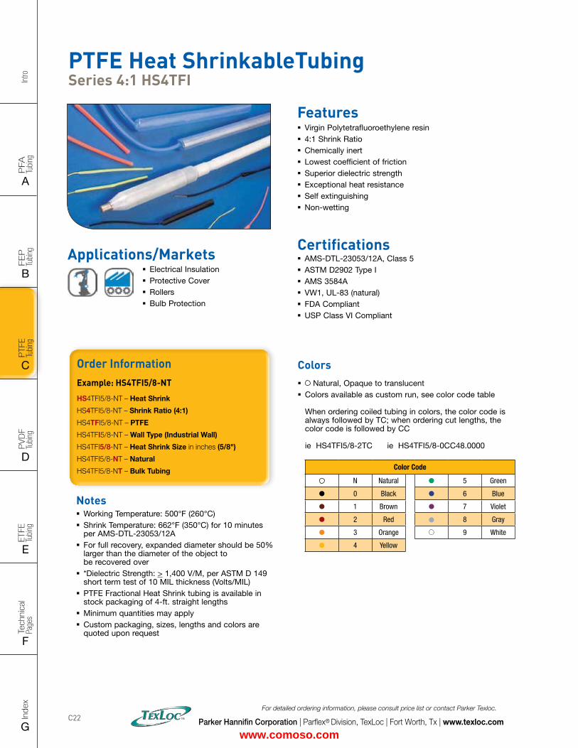
Intro
PFA
Tu
bing
A
FEP
Tu
bing
B
PVD
F
Tubi
ng
D
PTFE
Tu
bing
C
Index
G
Tech
nica
l Pa
ges
F
ETFE
Tu
bing
E
Parker Hannifin Corporation | Parflex® Division, TexLoc | Fort Worth, Tx | www.texloc.com
For detailed ordering information, please consult price list or contact Parker Texloc.
C22
PTFE Heat ShrinkableTubing Series 4:1 HS4TFI
Features � Virgin Polytetrafluoroethylene resin � 4:1 Shrink Ratio � Chemically inert � Lowest coefficient of friction � Superior dielectric strength � Exceptional heat resistance � Self extinguishing � Non-wetting
Certifications � AMS-DTL-23053/12A, Class 5 � ASTM D2902 Type I � AMS 3584A � VW1, UL-83 (natural) � FDA Compliant � USP Class VI Compliant
Applications/Markets � Electrical Insulation � Protective Cover � Rollers � Bulb Protection
Notes � Working Temperature: 500°F (260°C) � Shrink Temperature: 662°F (350°C) for 10 minutes per AMS-DTL-23053/12A
� For full recovery, expanded diameter should be 50% larger than the diameter of the object to be recovered over
� *Dielectric Strength: > 1,400 V/M, per ASTM D 149 short term test of 10 MIL thickness (Volts/MIL)
� PTFE Fractional Heat Shrink tubing is available in stock packaging of 4-ft. straight lengths
� Minimum quantities may apply � Custom packaging, sizes, lengths and colors are quoted upon request
Order InformationExample: HS4TFI5/8-NT
HS4TFI5/8-NT – Heat Shrink
HS4TFI5/8-NT – Shrink Ratio (4:1)
HS4TFI5/8-NT – PTFE
HS4TFI5/8-NT – Wall Type (Industrial Wall)
HS4TFI5/8-NT – Heat Shrink Size in inches (5/8")
HS4TFI5/8-NT – Natural
HS4TFI5/8-NT – Bulk Tubing
Colors � Natural, Opaque to translucent � Colors available as custom run, see color code table When ordering coiled tubing in colors, the color code is always followed by TC; when ordering cut lengths, the color code is followed by CC ie HS4TFI5/8-2TC ie HS4TFI5/8-0CC48.0000
Color Code
N Natural 5 Green
0 Black 6 Blue
1 Brown 7 Violet
2 Red 8 Gray
3 Orange 9 White
4 Yellow
www.comoso.com
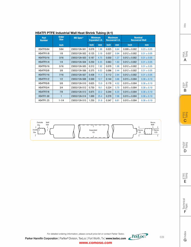
FLAT SIZE – 8.5" X 11" (11 x 17 spreads to be separated during final gather)CUT SIZE – 8.5" X 11"BLEED SIZE – 8.75” X 11.25”FINISHINGS – Drill holes
Intro
PFA
Tu
bing
A
FEP
Tu
bing
B
PVD
F
Tubi
ng
D
PTFE
Tu
bing
C
Index
G
Tech
nica
l Pa
ges
F
ETFE
Tu
bing
E
Parker Hannifin Corporation | Parflex® Division, TexLoc | Fort Worth, Tx | www.texloc.com
For detailed ordering information, please consult price list or contact Parker Texloc.
C23
HS4TFI PTFE Industrial Wall Heat Shrink Tubing (4:1)
Part Number
Order Size
inch
Mil Spec* Minimum Expanded I.D.
Maximum Recovered I.D.
Nominal Recovered Wall
inch mm inch mm inch mm
HS4TFI5/64 5/64 23053/12A-501 0.078 1.98 0.025 0.64 0.009 ± 0.002 0.23 ± 0.05
HS4TFI1/8 1/8 23053/12A-502 0.125 3.18 0.037 0.94 0.012 ± 0.002 0.31 ± 0.05
HS4TFI3/16 3/16 23053/12A-503 0.187 4.75 0.050 1.27 0.012 ± 0.002 0.31 ± 0.05
HS4TFI1/4 1/4 23053/12A-504 0.250 6.35 0.063 1.60 0.012 ± 0.002 0.31 ± 0.05
HS4TFI5/16 5/16 23053/12A-505 0.312 7.92 0.078 1.98 0.012 ± 0.002 0.31 ± 0.05
HS4TFI3/8 3/8 23053/12A-506 0.375 9.52 0.096 2.44 0.012 ± 0.002 0.31 ± 0.05
HS4TFI7/16 7/16 23053/12A-507 0.438 11.1 0.112 2.84 0.012 ± 0.002 0.31 ± 0.05
HS4TFI1/2 1/2 23053/12A-508 0.500 12.7 0.144 3.66 0.015 ± 0.004 0.38 ± 0.10
HS4TFI5/8 5/8 23053/12A-510 0.625 15.9 0.178 4.52 0.015 ± 0.004 0.38 ± 0.10
HS4TFI3/4 3/4 23053/12A-512 0.750 19.1 0.224 5.70 0.015 ± 0.004 0.38 ± 0.10
HS4TFI7/8 7/8 23053/12A-513 0.875 22.2 0.244 6.20 0.015 ± 0.004 0.38 ± 0.10
HS4TFI1.00 1 23053/12A-514 1.000 25.4 0.278 7.06 0.015 ± 0.004 0.38 ± 0.10
HS4TFI1.25 1-1/4 23053/12A-515 1.250 31.8 0.347 8.81 0.015 ± 0.004 0.38 ± 0.10
Recov. Wall
Recov. O.D.
Outside Dia.
Inside Dia.
WallSize
Recov. I.D.
Expanded I.D.
www.comoso.com
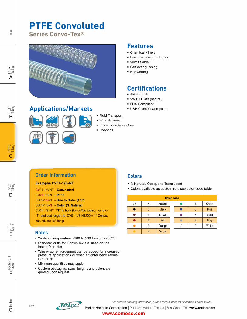
Intro
PFA
Tu
bing
A
FEP
Tu
bing
B
PVD
F
Tubi
ng
D
PTFE
Tu
bing
C
Index
G
Tech
nica
l Pa
ges
F
ETFE
Tu
bing
E
Parker Hannifin Corporation | Parflex® Division, TexLoc | Fort Worth, Tx | www.texloc.com
For detailed ordering information, please consult price list or contact Parker Texloc.
C24
PTFE Convoluted Series Convo-Tex®
Features � Chemically inert � Low coefficient of friction � Very flexible � Self extinguishing � Nonwetting
Certifications � AMS 3653E � VW1, UL-83 (natural) � FDA Compliant � USP Class VI Compliant
Order InformationExample: CV01-1/8-NT
CV01-1/8-NT – Convoluted
CV01-1/8-NT – PTFE
CV01-1/8-NT – Size to Order (1/8")
CV01-1/8-NT – Color (N=Natural)
CV01-1/8-NT– "T" is bulk (for cuffed tubing, remove
"T" and add length, ie. CV01-1/8-N1200 = 1" Convo,
natural, cut 12" long)
Notes � Working Temperature: -100 to 500°F/-75 to 260°C � Standard cuffs for Convo-Tex are sized on the Inside Diameter
� Wire wrap reinforcement can be added for increased pressure applications or when a tighter bend radius is needed
� Minimum quantities may apply � Custom packaging, sizes, lengths and colors are quoted upon request
Colors � Natural, Opaque to Translucent � Colors available as custom run, see color code table
Color Code
N Natural 5 Green
0 Black 6 Blue
1 Brown 7 Violet
2 Red 8 Gray
3 Orange 9 White
4 Yellow
Applications/Markets � Fluid Transport � Wire Harness � Protection/Cable Core � Robotics
www.comoso.com
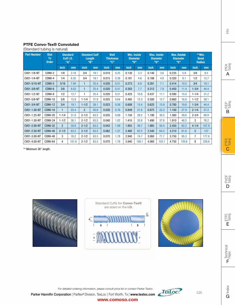
FLAT SIZE – 8.5" X 11" (11 x 17 spreads to be separated during final gather)CUT SIZE – 8.5" X 11"BLEED SIZE – 8.75” X 11.25”FINISHINGS – Drill holes
Intro
PFA
Tu
bing
A
FEP
Tu
bing
B
PVD
F
Tubi
ng
D
PTFE
Tu
bing
C
Index
G
Tech
nica
l Pa
ges
F
ETFE
Tu
bing
E
Parker Hannifin Corporation | Parflex® Division, TexLoc | Fort Worth, Tx | www.texloc.com
For detailed ordering information, please consult price list or contact Parker Texloc.
C25
PTFE Convo-Tex® Convoluted (Standard tubing is natural)
Part Number SizeTo
Order
Standard Cuff I.D.
“A”
Standard Cuff Length
“B”
Wall Thickness
"C"
Min. Inside Diameter
"D"
Max. Inside Diameter
"D"
Max. Outside Diameter
"E"
**Min. Bend
Radius
inch mm inch mm inch mm inch mm inch mm inch mm inch mm
CV01-1/8-NT CONV-2 1/8 3.18 3/4 19.1 0.010 0.25 0.130 3.3 0.140 3.6 0.235 5.9 3/8 9.5
CV01-1/4-NT CONV-4 1/4 6.35 3/4 19.1 0.015 0.38 0.181 4.6 0.188 4.8 0.320 8.1 1/2 12.7
CV01-5/16-NT CONV-5 5/16 7.94 1 25.4 0.020 0.51 0.273 6.9 0.281 7.1 0.414 10.5 3/4 19.1
CV01-3/8-NT CONV-6 3/8 9.53 1 25.4 0.020 0.51 0.303 7.7 0.312 7.9 0.450 11.4 1-3/4 44.4
CV01-1/2-NT CONV-8 1/2 12.7 1 25.4 0.020 0.51 0.425 10.8 0.437 11.1 0.590 15.0 1-1/4 31.2
CV01-5/8-NT CONV-10 5/8 15.9 1-1/4 31.8 0.025 0.64 0.485 12.3 0.500 12.7 0.660 16.8 1-1/2 38.1
CV01-3/4-NT CONV-12 3/4 19.1 1-1/2 38.1 0.023 0.58 0.608 15.4 0.625 15.9 0.780 19.8 1-3/4 44.4
CV01-1.00-NT CONV-16 1 25.4 2 50.8 0.030 0.76 0.849 21.6 0.875 22.2 1.100 27.9 2-1/4 57.2
CV01-1.25-NT CONV-20 1-1/4 31.8 2-1/2 63.5 0.035 0.89 1.150 29.2 1.190 30.2 1.560 39.6 2-3/4 69.9
CV01-1.50-NT CONV-24 1-1/2 38.1 2-1/2 63.5 0.040 1.02 1.410 35.8 1.490 37.8 1.910 48.5 3 76.2
CV01-2.00-NT CONV-32 2 50.8 2-1/2 63.5 0.043 1.09 1.955 49.7 1.985 50.4 2.450 62.2 4-1/4 107.9
CV01-2.50-NT CONV-40 2-1/2 63.5 2-1/2 63.5 0.062 1.57 2.460 62.5 2.540 64.5 3.210 81.6 5 127
CV01-3.00-NT CONV-48 3 76.2 2-1/2 63.5 0.070 1.78 2.940 74.7 3.060 77.7 3.750 95.3 7 177.8
CV01-4.00-NT CONV-64 4 101.6 2-1/2 63.5 0.070 1.78 3.940 100.1 4.060 103.1 4.750 120.6 9 228.6 ** Minimum 36" length.
Standard Cuffs for Convo-Tex® are sized on the I.D.
www.comoso.com
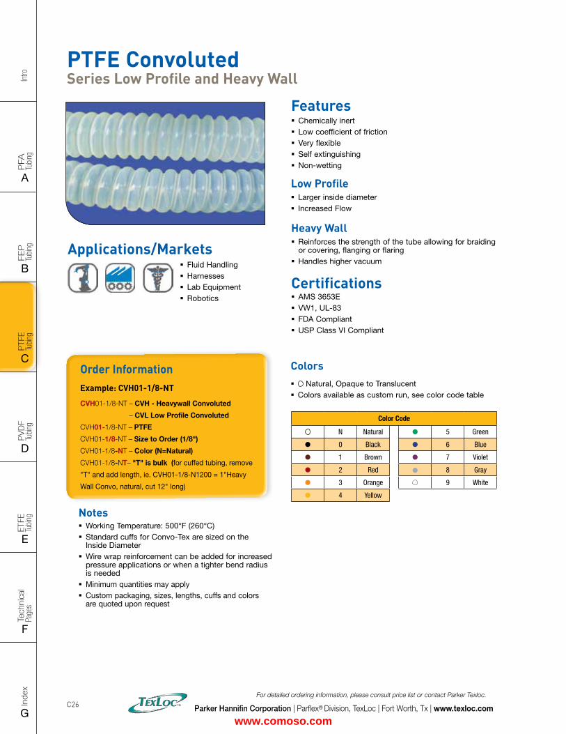
Intro
PFA
Tu
bing
A
FEP
Tu
bing
B
PVD
F
Tubi
ng
D
PTFE
Tu
bing
C
Index
G
Tech
nica
l Pa
ges
F
ETFE
Tu
bing
E
Parker Hannifin Corporation | Parflex® Division, TexLoc | Fort Worth, Tx | www.texloc.com
For detailed ordering information, please consult price list or contact Parker Texloc.
C26
PTFE Convoluted Series Low Profile and Heavy Wall
Features � Chemically inert � Low coefficient of friction � Very flexible � Self extinguishing � Non-wetting
Low Profile � Larger inside diameter � Increased Flow
Heavy Wall � Reinforces the strength of the tube allowing for braiding or covering, flanging or flaring
� Handles higher vacuum
Certifications � AMS 3653E � VW1, UL-83 � FDA Compliant � USP Class VI Compliant
Order InformationExample: CVH01-1/8-NT
CVH01-1/8-NT – CVH - Heavywall Convoluted
– CVL Low Profile Convoluted
CVH01-1/8-NT – PTFE
CVH01-1/8-NT – Size to Order (1/8")
CVH01-1/8-NT – Color (N=Natural)
CVH01-1/8-NT– "T" is bulk (for cuffed tubing, remove
"T" and add length, ie. CVH01-1/8-N1200 = 1"Heavy
Wall Convo, natural, cut 12" long)
Notes � Working Temperature: 500°F (260°C) � Standard cuffs for Convo-Tex are sized on the Inside Diameter
� Wire wrap reinforcement can be added for increased pressure applications or when a tighter bend radius is needed
� Minimum quantities may apply � Custom packaging, sizes, lengths, cuffs and colors are quoted upon request
Colors � Natural, Opaque to Translucent � Colors available as custom run, see color code table
Color Code
N Natural 5 Green
0 Black 6 Blue
1 Brown 7 Violet
2 Red 8 Gray
3 Orange 9 White
4 Yellow
Applications/Markets � Fluid Handling � Harnesses � Lab Equipment � Robotics
www.comoso.com
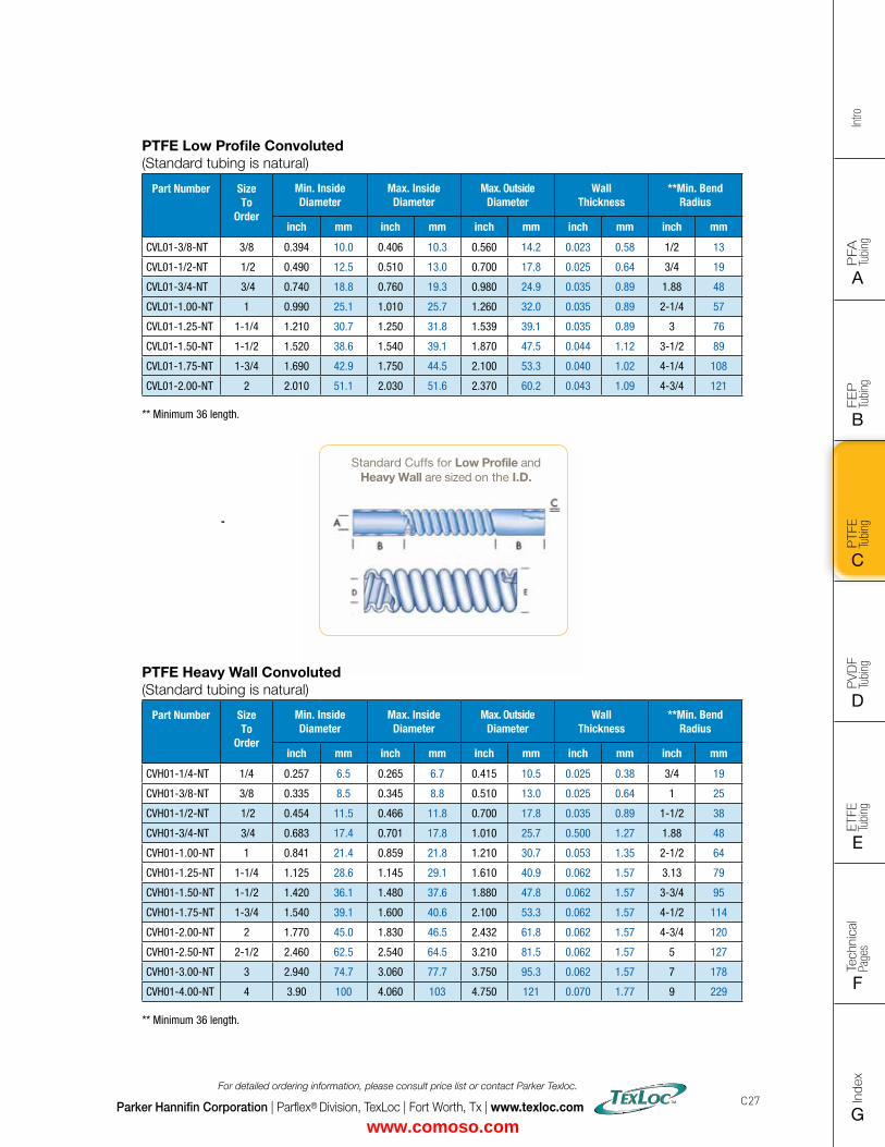
FLAT SIZE – 8.5" X 11" (11 x 17 spreads to be separated during final gather)CUT SIZE – 8.5" X 11"BLEED SIZE – 8.75” X 11.25”FINISHINGS – Drill holes
Intro
PFA
Tu
bing
A
FEP
Tu
bing
B
PVD
F
Tubi
ng
D
PTFE
Tu
bing
C
Index
G
Tech
nica
l Pa
ges
F
ETFE
Tu
bing
E
Parker Hannifin Corporation | Parflex® Division, TexLoc | Fort Worth, Tx | www.texloc.com
For detailed ordering information, please consult price list or contact Parker Texloc.
C27
PTFE Low Profile Convoluted (Standard tubing is natural)
Part Number SizeTo
Order
Min. Inside Diameter
Max. Inside Diameter
Max. Outside Diameter
Wall Thickness
**Min. Bend Radius
inch mm inch mm inch mm inch mm inch mm
CVL01-3/8-NT 3/8 0.394 10.0 0.406 10.3 0.560 14.2 0.023 0.58 1/2 13
CVL01-1/2-NT 1/2 0.490 12.5 0.510 13.0 0.700 17.8 0.025 0.64 3/4 19
CVL01-3/4-NT 3/4 0.740 18.8 0.760 19.3 0.980 24.9 0.035 0.89 1.88 48
CVL01-1.00-NT 1 0.990 25.1 1.010 25.7 1.260 32.0 0.035 0.89 2-1/4 57
CVL01-1.25-NT 1-1/4 1.210 30.7 1.250 31.8 1.539 39.1 0.035 0.89 3 76
CVL01-1.50-NT 1-1/2 1.520 38.6 1.540 39.1 1.870 47.5 0.044 1.12 3-1/2 89
CVL01-1.75-NT 1-3/4 1.690 42.9 1.750 44.5 2.100 53.3 0.040 1.02 4-1/4 108
CVL01-2.00-NT 2 2.010 51.1 2.030 51.6 2.370 60.2 0.043 1.09 4-3/4 121 ** Minimum 36 length.
Standard Cuffs for Low Profile and Heavy Wall are sized on the I.D.
PTFE Heavy Wall Convoluted (Standard tubing is natural)
Part Number SizeTo
Order
Min. Inside Diameter
Max. Inside Diameter
Max. Outside Diameter
Wall Thickness
**Min. Bend Radius
inch mm inch mm inch mm inch mm inch mm
CVH01-1/4-NT 1/4 0.257 6.5 0.265 6.7 0.415 10.5 0.025 0.38 3/4 19
CVH01-3/8-NT 3/8 0.335 8.5 0.345 8.8 0.510 13.0 0.025 0.64 1 25
CVH01-1/2-NT 1/2 0.454 11.5 0.466 11.8 0.700 17.8 0.035 0.89 1-1/2 38
CVH01-3/4-NT 3/4 0.683 17.4 0.701 17.8 1.010 25.7 0.500 1.27 1.88 48
CVH01-1.00-NT 1 0.841 21.4 0.859 21.8 1.210 30.7 0.053 1.35 2-1/2 64
CVH01-1.25-NT 1-1/4 1.125 28.6 1.145 29.1 1.610 40.9 0.062 1.57 3.13 79
CVH01-1.50-NT 1-1/2 1.420 36.1 1.480 37.6 1.880 47.8 0.062 1.57 3-3/4 95
CVH01-1.75-NT 1-3/4 1.540 39.1 1.600 40.6 2.100 53.3 0.062 1.57 4-1/2 114
CVH01-2.00-NT 2 1.770 45.0 1.830 46.5 2.432 61.8 0.062 1.57 4-3/4 120
CVH01-2.50-NT 2-1/2 2.460 62.5 2.540 64.5 3.210 81.5 0.062 1.57 5 127
CVH01-3.00-NT 3 2.940 74.7 3.060 77.7 3.750 95.3 0.062 1.57 7 178
CVH01-4.00-NT 4 3.90 100 4.060 103 4.750 121 0.070 1.77 9 229 ** Minimum 36 length.
www.comoso.com
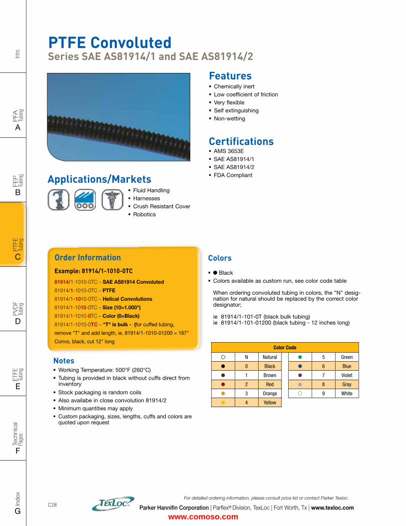
Intro
PFA
Tu
bing
A
FEP
Tu
bing
B
PVD
F
Tubi
ng
D
PTFE
Tu
bing
C
Index
G
Tech
nica
l Pa
ges
F
ETFE
Tu
bing
E
Parker Hannifin Corporation | Parflex® Division, TexLoc | Fort Worth, Tx | www.texloc.com
For detailed ordering information, please consult price list or contact Parker Texloc.
C28
PTFE Convoluted Series SAE AS81914/1 and SAE AS81914/2
Features � Chemically inert � Low coefficient of friction � Very flexible � Self extinguishing � Non-wetting
Certifications � AMS 3653E � SAE AS81914/1 � SAE AS81914/2 � FDA Compliant
Order InformationExample: 81914/1-1010-0TC
81914/1-1010-0TC – SAE AS81914 Convoluted
81914/1-1010-0TC – PTFE
81914/1-1010-0TC – Helical Convolutions
81914/1-1010-0TC – Size (10=1.000")
81914/1-1010-0TC – Color (0=Black)
81914/1-1010-0TC – "T" is bulk - (for cuffed tubing,
remove "T" and add length, ie. 81914/1-1010-01200 = 187"
Convo, black, cut 12" long
Notes � Working Temperature: 500°F (260°C) � Tubing is provided in black without cuffs direct from inventory
� Stock packaging is random coils � Also availabe in close convolution 81914/2 � Minimum quantities may apply � Custom packaging, sizes, lengths, cuffs and colors are quoted upon request
Colors
� Black � Colors available as custom run, see color code table When ordering convoluted tubing in colors, the "N" desig-nation for natural should be replaced by the correct color designator; ie 81914/1-101-0T (black bulk tubing) ie 81914/1-101-01200 (black tubing - 12 inches long)
Color Code
N Natural 5 Green
0 Black 6 Blue
1 Brown 7 Violet
2 Red 8 Gray
3 Orange 9 White
4 Yellow
Applications/Markets � Fluid Handling � Harnesses � Crush Resistant Cover � Robotics
www.comoso.com
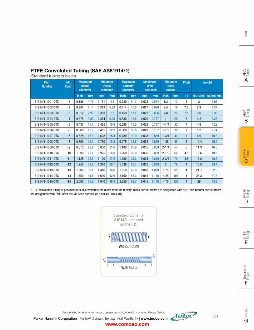
FLAT SIZE – 8.5" X 11" (11 x 17 spreads to be separated during final gather)CUT SIZE – 8.5" X 11"BLEED SIZE – 8.75” X 11.25”FINISHINGS – Drill holes
Intro
PFA
Tu
bing
A
FEP
Tu
bing
B
PVD
F
Tubi
ng
D
PTFE
Tu
bing
C
Index
G
Tech
nica
l Pa
ges
F
ETFE
Tu
bing
E
Parker Hannifin Corporation | Parflex® Division, TexLoc | Fort Worth, Tx | www.texloc.com
For detailed ordering information, please consult price list or contact Parker Texloc.
C29
PTFE Convoluted Tubing (SAE AS81914/1) (Standard tubing is black)
Part Number
MIL Spec*
Maximum Inside
Diameter
Minimum Inside
Diameter
Maximum Outside
Diameter
Maximum Wall
Thickness
Minimum Bend
Radius
Pitch Weight
inch mm inch mm inch mm inch mm inch mm ±1 lb./100 ft. kg./100 mtr.
81914/1-1001-0TC -1 0.188 4.78 0.181 4.6 0.320 8.13 0.023 0.584 1/2 13 8 2 2.98
81914/1-1002-0TC -2 0.281 7.14 0.273 6.93 0.414 10.5 0.027 0.686 3/4 19 7.5 2.9 4.31
81914/1-1003-0TC -3 0.312 7.93 0.303 7.7 0.450 11.4 0.027 0.686 7/8 22 7.5 3.6 5.36
81914/1-1004-0TC -4 0.375 9.53 0.364 9.25 0.530 13.5 0.029 0.737 1 25 7 4.2 6.25
81914/1-1005-0TC -5 0.437 11.1 0.425 10.8 0.590 15.0 0.029 0.737 1-1/4 32 7 4.9 7.29
81914/1-1006-0TC -6 0.500 12.7 0.485 12.3 0.660 16.8 0.029 0.737 1-1/2 38 7 5.2 7.74
81914/1-1007-0TC -7 0.625 15.9 0.608 15.4 0.780 19.9 0.035 0.889 1-3/4 44 7 6.9 10.3
81914/1-1008-0TC -8 0.750 19.1 0.730 18.5 0.975 24.8 0.035 0.889 1.88 48 6 10.4 15.5
81914/1-1009-0TC -9 0.875 22.2 0.850 21.6 1.100 27.9 0.035 0.889 2-1/4 57 6 11.3 16.8
81914/1-1010-0TC -10 1.000 25.4 0.975 24.8 1.260 32.0 0.035 0.889 2-1/2 64 4.5 12.6 18.8
81914/1-1011-0TC -11 1.125 28.6 1.100 27.9 1.390 35.3 0.035 0.889 2-3/4 70 4.5 13.8 20.5
81914/1-1012-0TC -12 1.250 31.8 1.210 30.7 1.539 39.1 0.035 0.889 3 76 4 15.5 23.1
81914/1-1013-0TC -13 1.500 38.1 1.440 36.6 1.810 46.0 0.040 1.020 3.75 95 4 21.7 32.3
81914/1-1014-0TC -14 1.750 44.5 1.690 42.9 2.100 53.3 0.045 1.140 4.25 108 4 25.3 37.6
81914/1-1015-0TC -15 2.000 50.8 1.940 49.3 2.350 59.7 0.045 1.140 4.75 121 4 29 43.2
*PTFE convoluted tubing is provided in BLACK without cuffs direct from the factory. Black part numbers are designated with “0T” and Natural part numbers are designated with "NT" after the Mil Spec number (ie 81914/1-1014-0T).
Standard Cuffs for81914/1 are sized
on the I.D.
With Cuffs
Without Cuffs
www.comoso.com
Intro
PFA
Tu
bing
A
FEP
Tu
bing
B
PVD
F
Tubi
ng
D
PTFE
Tu
bing
C
Index
G
Tech
nica
l Pa
ges
F
ETFE
Tu
bing
E
Parker Hannifin Corporation | Parflex® Division, TexLoc | Fort Worth, Tx | www.texloc.com
For detailed ordering information, please consult price list or contact Parker Texloc.
C30
Notes
www.comoso.com
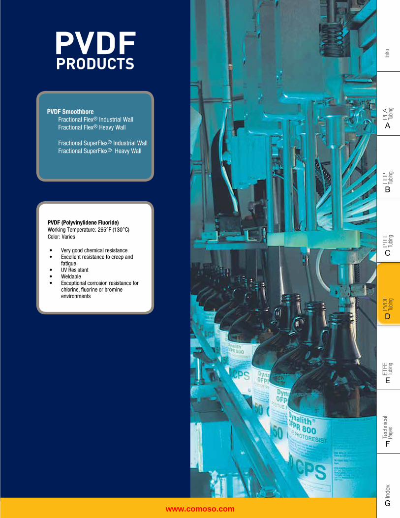
FLAT SIZE – 8.5" X 11" (11 x 17 spreads to be separated during final gather)CUT SIZE – 8.5" X 11"BLEED SIZE – 8.75” X 11.25”FINISHINGS – Drill holes
Intro
PFA
Tu
bing
A
FEP
Tu
bing
B
PVD
F
Tubi
ng
D
PTFE
Tu
bing
C
Index
G
Tech
nica
l Pa
ges
F
ETFE
Tu
bing
E
PFA PRODUCTS
PFA Smoothbore Industrial Wall Heavy Wall Metric High Purity Smoothbore Industrial Wall Heavy Wall Metric
Retractable Coils, Convoluted and Corrugated Tubing are located in the FEP Section
PFA PRODUCTS
PFA Smoothbore Industrial Wall Heavy Wall Metric High Purity Smoothbore Industrial Wall Heavy Wall Metric
Retractable Coils, Convoluted and Corrugated Tubing are located in the FEP Section
PVDF PRODUCTS
PVDF (Polyvinylidene Fluoride)Working Temperature: 265°F (130°C) Color: Varies
• Very good chemical resistance• Excellent resistance to creep and
fatigue• UV Resistant• Weldable• Exceptional corrosion resistance for
chlorine, fluorine or bromine environments
PVDF Smoothbore Fractional Flex® Industrial Wall Fractional Flex® Heavy Wall
Fractional SuperFlex® Industrial Wall Fractional SuperFlex® Heavy Wall
www.comoso.com
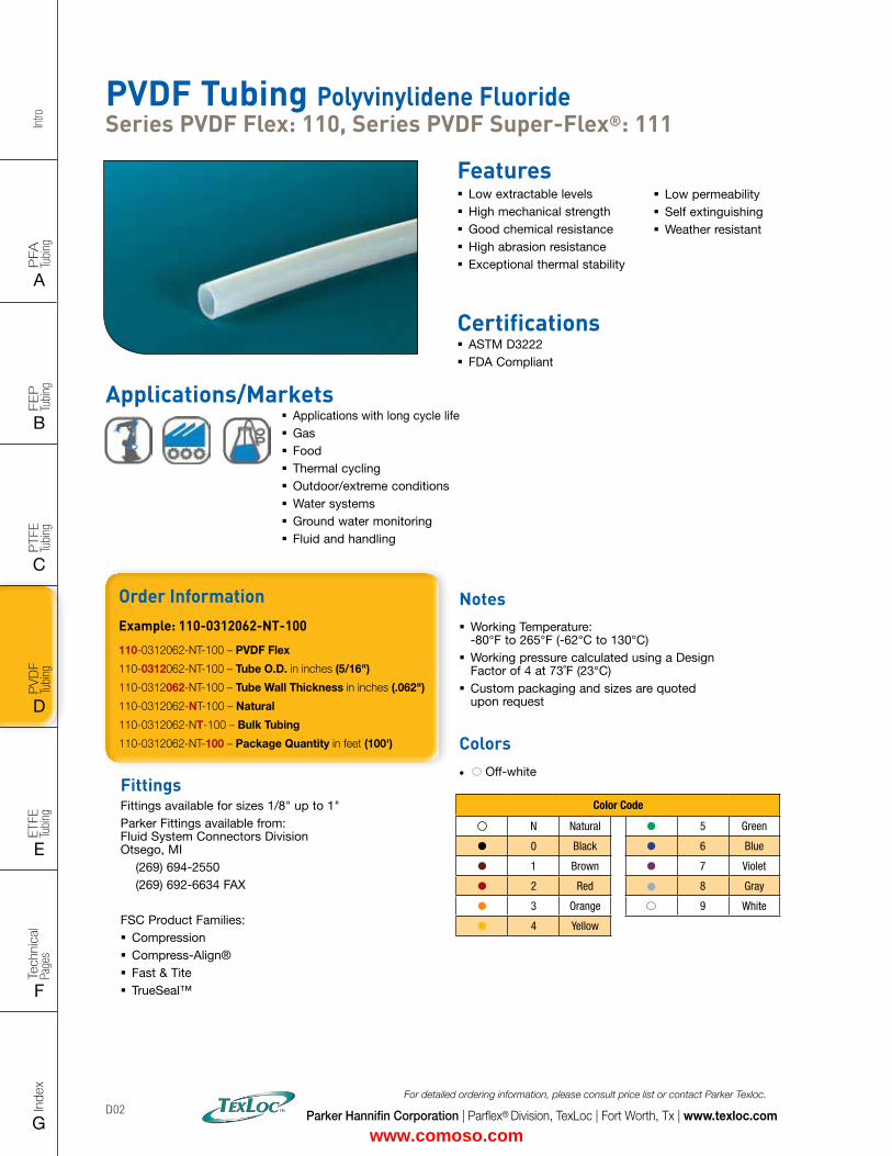
Intro
PFA
Tu
bing
A
FEP
Tu
bing
B
PVD
F
Tubi
ng
D
PTFE
Tu
bing
C
Index
G
Tech
nica
l Pa
ges
F
ETFE
Tu
bing
E
Parker Hannifin Corporation | Parflex® Division, TexLoc | Fort Worth, Tx | www.texloc.com
For detailed ordering information, please consult price list or contact Parker Texloc.
D02
PVDF Tubing Polyvinylidene Fluoride Series PVDF Flex: 110, Series PVDF Super-Flex®: 111
Features � Low extractable levels � High mechanical strength � Good chemical resistance � High abrasion resistance � Exceptional thermal stability
Certifications � ASTM D3222 � FDA Compliant
� Low permeability � Self extinguishing � Weather resistant
FittingsFittings available for sizes 1/8" up to 1"Parker Fittings available from: Fluid System Connectors Division Otsego, MI (269) 694-2550 (269) 692-6634 FAX
FSC Product Families: � Compression � Compress-Align® � Fast & Tite � TrueSeal™
Order InformationExample: 110-0312062-NT-100
110-0312062-NT-100 – PVDF Flex
110-0312062-NT-100 – Tube O.D. in inches (5/16")
110-0312062-NT-100 – Tube Wall Thickness in inches (.062")
110-0312062-NT-100 – Natural
110-0312062-NT-100 – Bulk Tubing
110-0312062-NT-100 – Package Quantity in feet (100')
Notes � Working Temperature: -80°F to 265°F (-62°C to 130°C)
� Working pressure calculated using a Design Factor of 4 at 73˚F (23°C)
� Custom packaging and sizes are quoted upon request
Colors• Off-white
Color Code
N Natural 5 Green
0 Black 6 Blue
1 Brown 7 Violet
2 Red 8 Gray
3 Orange 9 White
4 Yellow
Applications/Markets � Applications with long cycle life � Gas � Food � Thermal cycling � Outdoor/extreme conditions � Water systems � Ground water monitoring � Fluid and handling
www.comoso.com
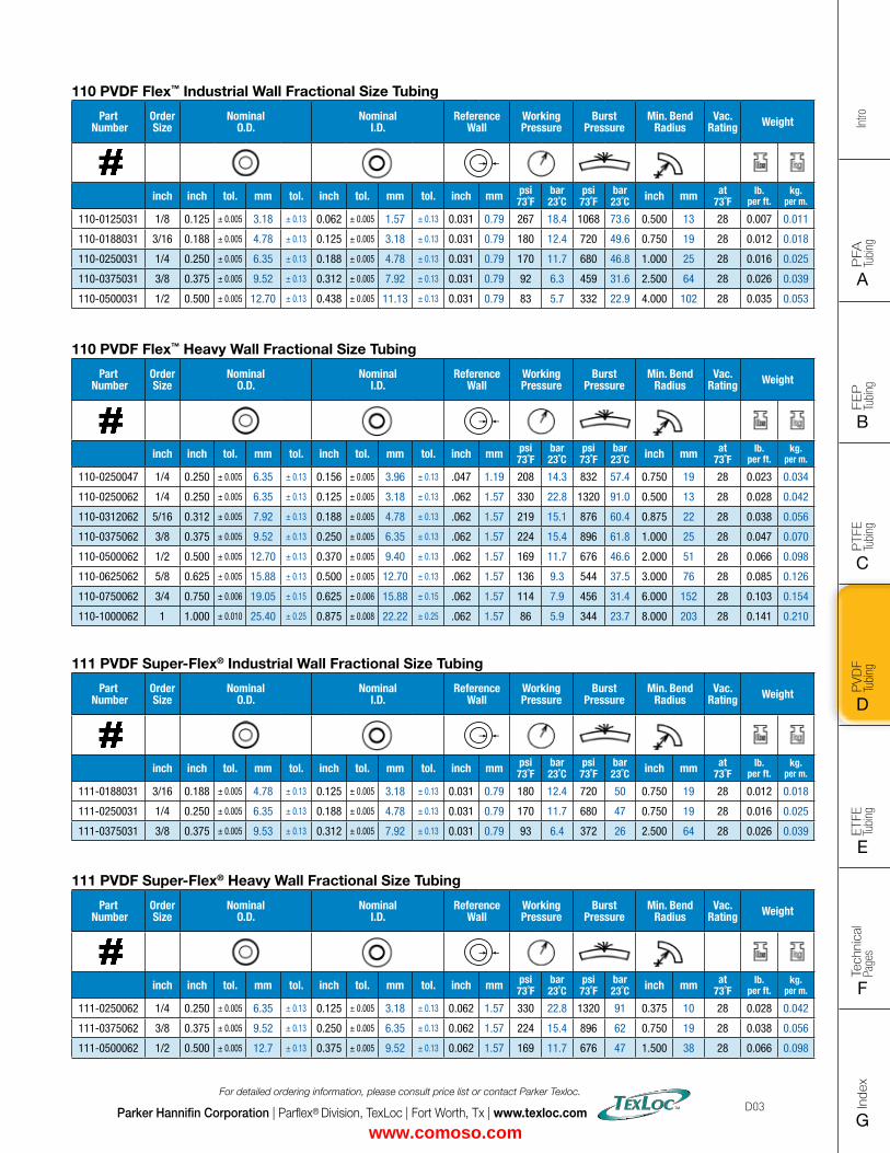
FLAT SIZE – 8.5" X 11" (11 x 17 spreads to be separated during final gather)CUT SIZE – 8.5" X 11"BLEED SIZE – 8.75” X 11.25”FINISHINGS – Drill holes
Intro
PFA
Tu
bing
A
FEP
Tu
bing
B
PVD
F
Tubi
ng
D
PTFE
Tu
bing
C
Index
G
Tech
nica
l Pa
ges
F
ETFE
Tu
bing
E
Parker Hannifin Corporation | Parflex® Division, TexLoc | Fort Worth, Tx | www.texloc.com
For detailed ordering information, please consult price list or contact Parker Texloc.
D03
110 PVDF Flex™ Industrial Wall Fractional Size Tubing
Part Number
Order Size
Nominal O.D.
Nominal I.D.
Reference Wall
Working Pressure
Burst Pressure
Min. Bend Radius
Vac. Rating Weight
inch inch tol. mm tol. inch tol. mm tol. inch mm psi73˚F
bar23˚C
psi73˚F
bar23˚C inch mm at
73˚Flb.
per ft.kg.
per m.
110-0125031 1/8 0.125 ± 0.005 3.18 ± 0.13 0.062 ± 0.005 1.57 ± 0.13 0.031 0.79 267 18.4 1068 73.6 0.500 13 28 0.007 0.011
110-0188031 3/16 0.188 ± 0.005 4.78 ± 0.13 0.125 ± 0.005 3.18 ± 0.13 0.031 0.79 180 12.4 720 49.6 0.750 19 28 0.012 0.018
110-0250031 1/4 0.250 ± 0.005 6.35 ± 0.13 0.188 ± 0.005 4.78 ± 0.13 0.031 0.79 170 11.7 680 46.8 1.000 25 28 0.016 0.025
110-0375031 3/8 0.375 ± 0.005 9.52 ± 0.13 0.312 ± 0.005 7.92 ± 0.13 0.031 0.79 92 6.3 459 31.6 2.500 64 28 0.026 0.039
110-0500031 1/2 0.500 ± 0.005 12.70 ± 0.13 0.438 ± 0.005 11.13 ± 0.13 0.031 0.79 83 5.7 332 22.9 4.000 102 28 0.035 0.053
110 PVDF Flex™ Heavy Wall Fractional Size Tubing
Part Number
Order Size
Nominal O.D.
Nominal I.D.
Reference Wall
Working Pressure
Burst Pressure
Min. Bend Radius
Vac. Rating Weight
inch inch tol. mm tol. inch tol. mm tol. inch mm psi73˚F
bar23˚C
psi73˚F
bar23˚C inch mm at
73˚Flb.
per ft.kg.
per m.
110-0250047 1/4 0.250 ± 0.005 6.35 ± 0.13 0.156 ± 0.005 3.96 ± 0.13 .047 1.19 208 14.3 832 57.4 0.750 19 28 0.023 0.034
110-0250062 1/4 0.250 ± 0.005 6.35 ± 0.13 0.125 ± 0.005 3.18 ± 0.13 .062 1.57 330 22.8 1320 91.0 0.500 13 28 0.028 0.042
110-0312062 5/16 0.312 ± 0.005 7.92 ± 0.13 0.188 ± 0.005 4.78 ± 0.13 .062 1.57 219 15.1 876 60.4 0.875 22 28 0.038 0.056
110-0375062 3/8 0.375 ± 0.005 9.52 ± 0.13 0.250 ± 0.005 6.35 ± 0.13 .062 1.57 224 15.4 896 61.8 1.000 25 28 0.047 0.070
110-0500062 1/2 0.500 ± 0.005 12.70 ± 0.13 0.370 ± 0.005 9.40 ± 0.13 .062 1.57 169 11.7 676 46.6 2.000 51 28 0.066 0.098
110-0625062 5/8 0.625 ± 0.005 15.88 ± 0.13 0.500 ± 0.005 12.70 ± 0.13 .062 1.57 136 9.3 544 37.5 3.000 76 28 0.085 0.126
110-0750062 3/4 0.750 ± 0.006 19.05 ± 0.15 0.625 ± 0.006 15.88 ± 0.15 .062 1.57 114 7.9 456 31.4 6.000 152 28 0.103 0.154
110-1000062 1 1.000 ± 0.010 25.40 ± 0.25 0.875 ± 0.008 22.22 ± 0.25 .062 1.57 86 5.9 344 23.7 8.000 203 28 0.141 0.210
111 PVDF Super-Flex® Industrial Wall Fractional Size Tubing
Part Number
Order Size
Nominal O.D.
Nominal I.D.
Reference Wall
Working Pressure
Burst Pressure
Min. Bend Radius
Vac. Rating Weight
inch inch tol. mm tol. inch tol. mm tol. inch mm psi73˚F
bar23˚C
psi73˚F
bar23˚C inch mm at
73˚Flb.
per ft.kg.
per m.
111-0188031 3/16 0.188 ± 0.005 4.78 ± 0.13 0.125 ± 0.005 3.18 ± 0.13 0.031 0.79 180 12.4 720 50 0.750 19 28 0.012 0.018
111-0250031 1/4 0.250 ± 0.005 6.35 ± 0.13 0.188 ± 0.005 4.78 ± 0.13 0.031 0.79 170 11.7 680 47 0.750 19 28 0.016 0.025
111-0375031 3/8 0.375 ± 0.005 9.53 ± 0.13 0.312 ± 0.005 7.92 ± 0.13 0.031 0.79 93 6.4 372 26 2.500 64 28 0.026 0.039
111 PVDF Super-Flex® Heavy Wall Fractional Size Tubing
Part Number
Order Size
Nominal O.D.
Nominal I.D.
Reference Wall
Working Pressure
Burst Pressure
Min. Bend Radius
Vac. Rating Weight
inch inch tol. mm tol. inch tol. mm tol. inch mm psi73˚F
bar23˚C
psi73˚F
bar23˚C inch mm at
73˚Flb.
per ft.kg.
per m.
111-0250062 1/4 0.250 ± 0.005 6.35 ± 0.13 0.125 ± 0.005 3.18 ± 0.13 0.062 1.57 330 22.8 1320 91 0.375 10 28 0.028 0.042
111-0375062 3/8 0.375 ± 0.005 9.52 ± 0.13 0.250 ± 0.005 6.35 ± 0.13 0.062 1.57 224 15.4 896 62 0.750 19 28 0.038 0.056
111-0500062 1/2 0.500 ± 0.005 12.7 ± 0.13 0.375 ± 0.005 9.52 ± 0.13 0.062 1.57 169 11.7 676 47 1.500 38 28 0.066 0.098
www.comoso.com
Intro
PFA
Tu
bing
A
FEP
Tu
bing
B
PVD
F
Tubi
ng
D
PTFE
Tu
bing
C
Index
G
Tech
nica
l Pa
ges
F
ETFE
Tu
bing
E
Parker Hannifin Corporation | Parflex® Division, TexLoc | Fort Worth, Tx | www.texloc.com
For detailed ordering information, please consult price list or contact Parker Texloc.
D04
Notes
www.comoso.com
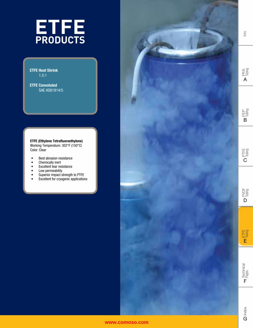
FLAT SIZE – 8.5" X 11" (11 x 17 spreads to be separated during final gather)CUT SIZE – 8.5" X 11"BLEED SIZE – 8.75” X 11.25”FINISHINGS – Drill holes
Intro
PFA
Tu
bing
A
FEP
Tu
bing
B
PVD
F
Tubi
ng
D
PTFE
Tu
bing
C
Index
G
Tech
nica
l Pa
ges
F
ETFE
Tu
bing
E
PFA PRODUCTS
PFA Smoothbore Industrial Wall Heavy Wall Metric High Purity Smoothbore Industrial Wall Heavy Wall Metric
Retractable Coils, Convoluted and Corrugated Tubing are located in the FEP Section
PFA PRODUCTS
PFA Smoothbore Industrial Wall Heavy Wall Metric High Purity Smoothbore Industrial Wall Heavy Wall Metric
Retractable Coils, Convoluted and Corrugated Tubing are located in the FEP Section
ETFE PRODUCTS
ETFE (Ethylene Tetrafluoroethylene)Working Temperature: 302°F (150°C) Color: Clear
• Best abrasion resistance• Chemically inert• Excellent tear resistance• Low permeability• Superior impact strength to PTFE• Excellent for cryogenic applications
ETFE Heat Shrink 1.5:1
ETFE Convoluted SAE AS81914/5
www.comoso.com
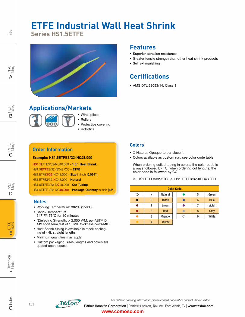
Intro
PFA
Tu
bing
A
FEP
Tu
bing
B
PVD
F
Tubi
ng
D
PTFE
Tu
bing
C
Index
G
Tech
nica
l Pa
ges
F
ETFE
Tu
bing
E
Parker Hannifin Corporation | Parflex® Division, TexLoc | Fort Worth, Tx | www.texloc.com
For detailed ordering information, please consult price list or contact Parker Texloc.
E02
Order InformationExample: HS1.5ETFE3/32-NC48.000
HS1.5ETFE3/32-NC48.000 – 1.5:1 Heat Shrink
HS1.5ETFE3/32-NC48.000 – ETFE
HS1.ETFE3/32-NC48.000 – Size in inch (0.094")
HS1.ETFE3/32-NC48.000 – Natural
HS1.5ETFE3/32-NC48.000 – Cut Tubing
HS1.5ETFE3/32-NC48.000 – Package Quantity in inch (48")
Notes � Working Temperature: 302°F (150°C) � Shrink Temperature 347°F/175°C for 10 minutes
� *Dielectric Strength: > 2,000 V/M, per ASTM D 149 short term test of 10 MIL thickness (Volts/MIL)
� Heat Shrink tubing is available in stock packag-ing of 4-ft. straight lengths
� Minimum quantities may apply � Custom packaging, sizes, lengths and colors are quoted upon request
ETFE Industrial Wall Heat Shrink Series HS1.5ETFE
Features � Superior abrasion resistance � Greater tensile strength than other heat shrink products � Self extinguishing
Certifications � AMS DTL 23053/14, Class 1
Colors � Natural, Opaque to translucent � Colors available as custom run, see color code table When ordering coiled tubing in colors, the color code is always followed by TC; when ordering cut lengths, the color code is followed by CC ie HS1.ETFE3/32-2TC ie HS1.ETFE3/32-0CC48.0000
Color Code
N Natural 5 Green
0 Black 6 Blue
1 Brown 7 Violet
2 Red 8 Gray
3 Orange 9 White
4 Yellow
Applications/Markets � Wire splices � Rollers � Protective covering � Robotics
www.comoso.com
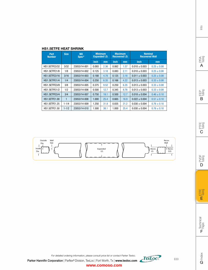
FLAT SIZE – 8.5" X 11" (11 x 17 spreads to be separated during final gather)CUT SIZE – 8.5" X 11"BLEED SIZE – 8.75” X 11.25”FINISHINGS – Drill holes
Intro
PFA
Tu
bing
A
FEP
Tu
bing
B
PVD
F
Tubi
ng
D
PTFE
Tu
bing
C
Index
G
Tech
nica
l Pa
ges
F
ETFE
Tu
bing
E
Parker Hannifin Corporation | Parflex® Division, TexLoc | Fort Worth, Tx | www.texloc.com
For detailed ordering information, please consult price list or contact Parker Texloc.
E03
Recov. Wall
Recov. O.D.
Outside Dia.
Inside Dia.
WallSize
Recov. I.D.
Expanded I.D.
HS1.5ETFE HEAT SHRINK
Part Number
Size Mil Spec*
Minimum Expanded I.D.
MaximumRecovered I.D.
Nominal Recovered Wall
inch mm inch mm inch mm
HS1.5ETFE3/32 3/32 23053/14-001 0.093 2.36 0.062 1.57 0.010 ± 0.003 0.25 ± 0.08
HS1.5ETFE1/8 1/8 23053/14-002 0.125 3.18 0.083 2.11 0.010 ± 0.003 0.25 ± 0.08
HS1.5ETFE3/16 3/16 23053/14-003 0.188 4.78 0.125 3.18 0.011 ± 0.003 0.25 ± 0.08
HS1.5ETFE1/4 1/4 23053/14-004 0.250 6.35 0.166 4.22 0.013 ± 0.003 0.33 ± 0.08
HS1.5ETFE3/8 3/8 23053/14-005 0.375 9.52 0.250 6.35 0.013 ± 0.003 0.33 ± 0.08
HS1.5ETFE1/2 1/2 23053/14-006 0.500 12.7 0.345 8.76 0.013 ± 0.003 0.33 ± 0.08
HS1.5ETFE3/4 3/4 23053/14-007 0.750 19.1 0.500 12.7 0.018 ± 0.004 0.46 ± 0.10
HS1.5ETFE1.00 1 23053/14-008 1.000 25.4 0.665 16.9 0.022 ± 0.004 0.51 ± 0.10
HS1.5ETFE1.25 1-1/4 23053/14-009 1.250 31.8 0.835 21.2 0.030 ± 0.004 0.76 ± 0.10
HS1.5ETFE1.50 1-1/2 23053/14-010 1.500 38.1 1.000 25.4 0.030 ± 0.004 0.76 ± 0.10
www.comoso.com
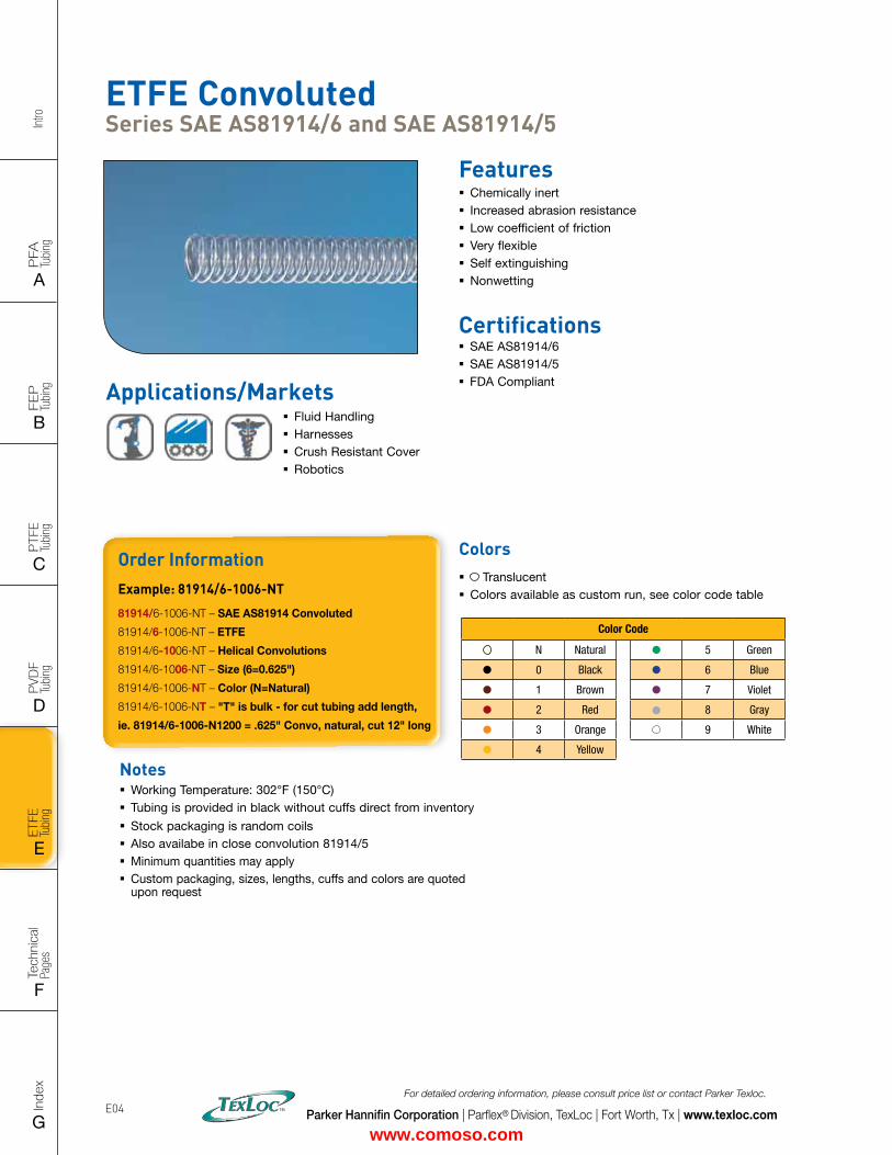
Intro
PFA
Tu
bing
A
FEP
Tu
bing
B
PVD
F
Tubi
ng
D
PTFE
Tu
bing
C
Index
G
Tech
nica
l Pa
ges
F
ETFE
Tu
bing
E
Parker Hannifin Corporation | Parflex® Division, TexLoc | Fort Worth, Tx | www.texloc.com
For detailed ordering information, please consult price list or contact Parker Texloc.
E04
Order InformationExample: 81914/6-1006-NT
81914/6-1006-NT – SAE AS81914 Convoluted
81914/6-1006-NT – ETFE
81914/6-1006-NT – Helical Convolutions
81914/6-1006-NT – Size (6=0.625")
81914/6-1006-NT – Color (N=Natural)
81914/6-1006-NT – "T" is bulk - for cut tubing add length,
ie. 81914/6-1006-N1200 = .625" Convo, natural, cut 12" long
Notes � Working Temperature: 302°F (150°C) � Tubing is provided in black without cuffs direct from inventory
� Stock packaging is random coils � Also availabe in close convolution 81914/5 � Minimum quantities may apply � Custom packaging, sizes, lengths, cuffs and colors are quoted upon request
ETFE Convoluted Series SAE AS81914/6 and SAE AS81914/5
Features � Chemically inert � Increased abrasion resistance � Low coefficient of friction � Very flexible � Self extinguishing � Nonwetting
Certifications � SAE AS81914/6 � SAE AS81914/5 � FDA Compliant
Colors � Translucent � Colors available as custom run, see color code table
Color Code
N Natural 5 Green
0 Black 6 Blue
1 Brown 7 Violet
2 Red 8 Gray
3 Orange 9 White
4 Yellow
Applications/Markets � Fluid Handling � Harnesses � Crush Resistant Cover � Robotics
www.comoso.com
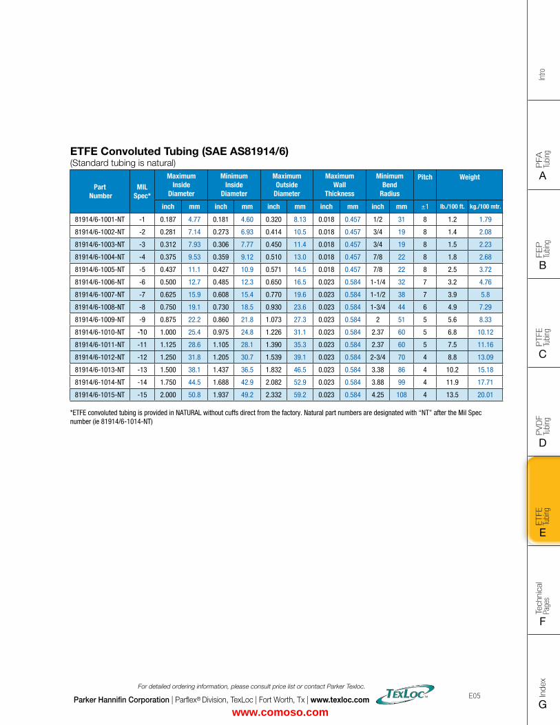
FLAT SIZE – 8.5" X 11" (11 x 17 spreads to be separated during final gather)CUT SIZE – 8.5" X 11"BLEED SIZE – 8.75” X 11.25”FINISHINGS – Drill holes
Intro
PFA
Tu
bing
A
FEP
Tu
bing
B
PVD
F
Tubi
ng
D
PTFE
Tu
bing
C
Index
G
Tech
nica
l Pa
ges
F
ETFE
Tu
bing
E
Parker Hannifin Corporation | Parflex® Division, TexLoc | Fort Worth, Tx | www.texloc.com
For detailed ordering information, please consult price list or contact Parker Texloc.
E05
ETFE Convoluted Tubing (SAE AS81914/6) (Standard tubing is natural)
Part Number
MIL Spec*
Maximum Inside
Diameter
Minimum Inside
Diameter
Maximum Outside
Diameter
Maximum Wall
Thickness
Minimum Bend
Radius
Pitch Weight
inch mm inch mm inch mm inch mm inch mm ±1 lb./100 ft. kg./100 mtr.
81914/6-1001-NT -1 0.187 4.77 0.181 4.60 0.320 8.13 0.018 0.457 1/2 31 8 1.2 1.79
81914/6-1002-NT -2 0.281 7.14 0.273 6.93 0.414 10.5 0.018 0.457 3/4 19 8 1.4 2.08
81914/6-1003-NT -3 0.312 7.93 0.306 7.77 0.450 11.4 0.018 0.457 3/4 19 8 1.5 2.23
81914/6-1004-NT -4 0.375 9.53 0.359 9.12 0.510 13.0 0.018 0.457 7/8 22 8 1.8 2.68
81914/6-1005-NT -5 0.437 11.1 0.427 10.9 0.571 14.5 0.018 0.457 7/8 22 8 2.5 3.72
81914/6-1006-NT -6 0.500 12.7 0.485 12.3 0.650 16.5 0.023 0.584 1-1/4 32 7 3.2 4.76
81914/6-1007-NT -7 0.625 15.9 0.608 15.4 0.770 19.6 0.023 0.584 1-1/2 38 7 3.9 5.8
81914/6-1008-NT -8 0.750 19.1 0.730 18.5 0.930 23.6 0.023 0.584 1-3/4 44 6 4.9 7.29
81914/6-1009-NT -9 0.875 22.2 0.860 21.8 1.073 27.3 0.023 0.584 2 51 5 5.6 8.33
81914/6-1010-NT -10 1.000 25.4 0.975 24.8 1.226 31.1 0.023 0.584 2.37 60 5 6.8 10.12
81914/6-1011-NT -11 1.125 28.6 1.105 28.1 1.390 35.3 0.023 0.584 2.37 60 5 7.5 11.16
81914/6-1012-NT -12 1.250 31.8 1.205 30.7 1.539 39.1 0.023 0.584 2-3/4 70 4 8.8 13.09
81914/6-1013-NT -13 1.500 38.1 1.437 36.5 1.832 46.5 0.023 0.584 3.38 86 4 10.2 15.18
81914/6-1014-NT -14 1.750 44.5 1.688 42.9 2.082 52.9 0.023 0.584 3.88 99 4 11.9 17.71
81914/6-1015-NT -15 2.000 50.8 1.937 49.2 2.332 59.2 0.023 0.584 4.25 108 4 13.5 20.01
*ETFE convoluted tubing is provided in NATURAL without cuffs direct from the factory. Natural part numbers are designated with “NT” after the Mil Spec number (ie 81914/6-1014-NT)
www.comoso.com
Intro
PFA
Tu
bing
A
FEP
Tu
bing
B
PVD
F
Tubi
ng
D
PTFE
Tu
bing
C
Index
G
Tech
nica
l Pa
ges
F
ETFE
Tu
bing
E
Intro
PFA
Tu
bing
A
FEP
Tu
bing
B
PVD
F
Tubi
ng
D
PTFE
Tu
bing
C
Tech
nica
l Pa
ges
F
ETFE
Tu
bing
E
Parker Hannifin Corporation | Parflex® Division, TexLoc | Fort Worth, Tx | www.texloc.com
For detailed ordering information, please consult price list or contact Parker Texloc.
E06
Notes
www.comoso.com
FLAT SIZE – 8.5" X 11" (11 x 17 spreads to be separated during final gather)CUT SIZE – 8.5" X 11"BLEED SIZE – 8.75” X 11.25”FINISHINGS – Drill holes
Intro
PFA
Tu
bing
A
FEP
Tu
bing
B
PVD
F
Tubi
ng
D
PTFE
Tu
bing
C
Index
G
Tech
nica
l Pa
ges
F
ETFE
Tu
bing
E
PFA PRODUCTS
PFA Smoothbore Industrial Wall Heavy Wall Metric High Purity Smoothbore Industrial Wall Heavy Wall Metric
Retractable Coils, Convoluted and Corrugated Tubing are located in the FEP Section
PFA PRODUCTS
PFA Smoothbore Industrial Wall Heavy Wall Metric High Purity Smoothbore Industrial Wall Heavy Wall Metric
Retractable Coils, Convoluted and Corrugated Tubing are located in the FEP Section
Technical INFO
Property Quick Reference Property Comparison Chart
Chemical Resistance Guide
Parker Safety Guide
Parker Offer of Sale
Parker Hannifin Corporation | Parflex® Division, TexLoc | Fort Worth, Tx | www.texloc.com F01
www.comoso.com
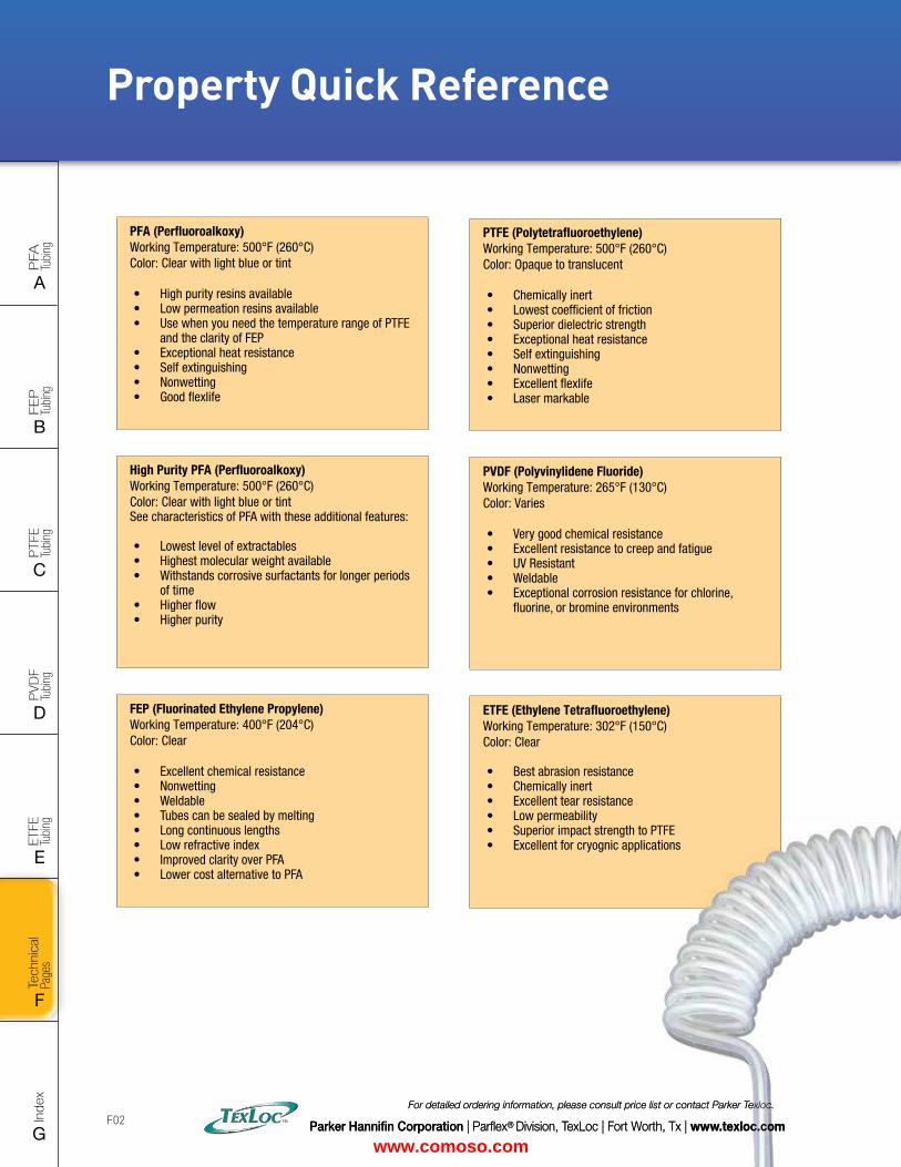
Intro
PFA
Tu
bing
A
FEP
Tu
bing
B
PVD
F
Tubi
ng
D
PTFE
Tu
bing
C
Index
G
Tech
nica
l Pa
ges
F
ETFE
Tu
bing
E
Parker Hannifin Corporation | Parflex® Division, TexLoc | Fort Worth, Tx | www.texloc.com
For detailed ordering information, please consult price list or contact Parker Texloc.
F02
PFA (Perfluoroalkoxy)Working Temperature: 500°F (260°C) Color: Clear with light blue or tint
• High purity resins available• Low permeation resins available• Use when you need the temperature range of PTFE
and the clarity of FEP• Exceptional heat resistance• Self extinguishing• Nonwetting• Good flexlife
High Purity PFA (Perfluoroalkoxy)Working Temperature: 500°F (260°C) Color: Clear with light blue or tint See characteristics of PFA with these additional features:
• Lowest level of extractables• Highest molecular weight available• Withstands corrosive surfactants for longer periods
of time• Higher flow• Higher purity
FEP (Fluorinated Ethylene Propylene)Working Temperature: 400°F (204°C) Color: Clear
• Excellent chemical resistance• Nonwetting• Weldable• Tubes can be sealed by melting• Long continuous lengths• Low refractive index• Improved clarity over PFA• Lower cost alternative to PFA
Property Quick Reference
PTFE (Polytetrafluoroethylene)Working Temperature: 500°F (260°C) Color: Opaque to translucent
• Chemically inert• Lowest coefficient of friction• Superior dielectric strength• Exceptional heat resistance• Self extinguishing• Nonwetting• Excellent flexlife• Laser markable
PVDF (Polyvinylidene Fluoride)Working Temperature: 265°F (130°C) Color: Varies
• Very good chemical resistance• Excellent resistance to creep and fatigue• UV Resistant• Weldable• Exceptional corrosion resistance for chlorine,
fluorine, or bromine environments
ETFE (Ethylene Tetrafluoroethylene)Working Temperature: 302°F (150°C) Color: Clear
• Best abrasion resistance• Chemically inert• Excellent tear resistance• Low permeability• Superior impact strength to PTFE• Excellent for cryognic applications
Parker Hannifin Corporation | Parflex® Division, TexLoc | Fort Worth, Tx | www.texloc.com
For detailed ordering information, please consult price list or contact Parker Texloc.
www.comoso.com
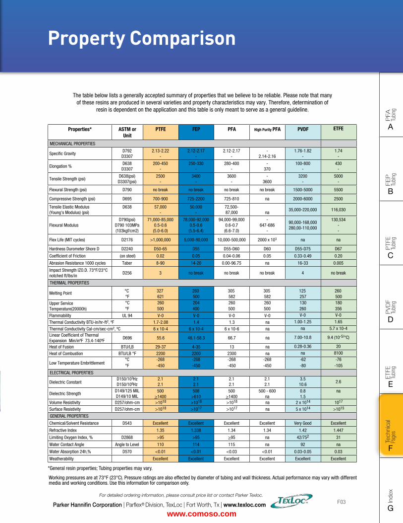
FLAT SIZE – 8.5" X 11" (11 x 17 spreads to be separated during final gather)CUT SIZE – 8.5" X 11"BLEED SIZE – 8.75” X 11.25”FINISHINGS – Drill holes
Intro
PFA
Tu
bing
A
FEP
Tu
bing
B
PVD
F
Tubi
ng
D
PTFE
Tu
bing
C
Index
G
Tech
nica
l Pa
ges
F
ETFE
Tu
bing
E
Parker Hannifin Corporation | Parflex® Division, TexLoc | Fort Worth, Tx | www.texloc.com
For detailed ordering information, please consult price list or contact Parker Texloc.
F03
Property Comparison
Working pressures are at 73°F (23°C). Pressure ratings are also effected by diameter of tubing and wall thickness. Actual performance may vary with different media and working conditions. Use this information for comparison only.
The table below lists a generally accepted summary of properties that we believe to be reliable. Please note that manyof these resins are produced in several varieties and property characteristics may vary. Therefore, determination of
resin is dependent on the application and this table is only meant to serve as a general guideline.
Properties* ASTM or Unit
PTFE FEP PFA High Purity PFA PVDF ETFE
MECHANICAL PROPERTIES
Specific GravityD792 D3307
2.13-2.22 -
2.12-2.17 -
2.12-2.17 -
- 2.14-2.16
1.76-1.82 -
1.74 -
Elongation %D638D3307
200-450 -
250-330 -
280-400 -
- 370
100-800 -
430 -
Tensile Strength (psi)D638(psi) D3307(psi)
2500-
3400 -
3600 -
- 3600
3200 -
5000-
Flexural Strength (psi) D790 no break no break no break no break 1500-5000 5500
Compressive Strength (psi) D695 700-900 725-2200 725-810 na 2000-6000 2500
Tensile Elastic Modulus (Young's Modulus) (psi)
D638 57,000 -
50,000 -
72,500- 87,000
na
35,000-220,000 116,030
Flexural Modulus D790(psi)
D790 103MPa (103kgf/cm2)
71,000-85,0000.5-0.6
(5.0-6.0)
78,000-92,0000.5-0.6
(5.5-6.4)
94,000-99,0000.6-0.7
(6.6-7.0)
- 647-686
-
90,000-168,000280,00-110,000
130,534 - -
Flex Life (MIT cycles) D2176 >1,000,000 5,000-80,000 10,000-500,000 2000 x 103 na na
Hardness Durometer Shore D D2240 D50-65 D55 D55-D60 D60 D55-D75 D67
Coefficient of Friction (on steel) 0.02 0.05 0.04-0.06 0.05 0.33-0.49 0.20
Abrasion Resistance 1000 cycles Taber 8-90 14-20 0.00-96.75 na 16-33 0.005
Impact Strength IZO.D. 73°F/23°C notched ft/lbs/in
D256 3 no break no break no break 4 no break
THERMAL PROPERTIES
Melting Point °C 327 260 305 305 125 260°F 621 500 582 582 257 500
Upper ServiceTemperature(20000h)
°C 260 204 260 260 130 180°F 500 400 500 500 260 356
Flammability UL 94 V-0 V-0 V-0 V-0 V-0 V-0
Thermal Conductivity BTU-in/hr-ft2, ºF 1.7-2.08 1.4 1.3 na 1.00-1.25 1.65
Thermal Conductivity Cal-cm/sec-cm2, ºC 6 x 10⁻⁴ 6 x 10⁻⁴ 6 x 10⁻⁶ na na 5.7 x 10⁻⁴
Linear Coefficient of Thermal Expansion Min/inºF 73.4-140ºF
D696 55.6 46.1-58.3 66.7 na 7.00-10.8 9.4 (10-5/°C)
Heat of Fusion BTU/LB 29-37 4-35 13 na 0.28-0.36 20
Heat of Combustion BTU/LB °F 2200 2200 2300 na na 8100
Low Temperature Embrittlement°C -268 -268 -268 -268 -62 -76°F -450 -450 -450 -450 -80 -105
ELECTRICAL PROPERTIES
Dielectric ConstantD150/103HzD150/106Hz
2.12.1
2.12.1
2.12.1
2.12.1
3.510.6
2.6
Dielectric StrengthD149/125 MIL D149/10 MIL
500 508 500 500 - 600 0.8 na>1400 >610 >1400 na 1.5
Volume Resistivity D257/ohm-cm >1018 >1018 >1018 na 2 x 10¹⁴ 1017
Surface Resistivity D257/ohm-cm >1018 >1017 >1017 na 5 x 10¹⁴ >1015
GENERAL PROPERTIES
Chemical/Solvent Resistance D543 Excellent Excellent Excellent Excellent Very Good Excellent
Refractive Index 1.35 1.338 1.34 1.34 1.42 1.447
Limiting Oxygen Index, % D2868 >95 >95 >95 na 42/752 31
Water Contact Angle Angle to Level 110 114 115 na 92 na
Water Absorption 24h,% D570 <0.01 <0.01 <0.03 <0.01 0.03-0.05 0.03
Weatherability Excellent Excellent Excellent Excellent Excellent Excellent
*General resin properties; Tubing properties may vary.
PFA (Perfluoroalkoxy)Working Temperature: 500°F (260°C) Color: Clear with light blue or tint
• High purity resins available• Low permeation resins available• Use when you need the temperature range of PTFE
and the clarity of FEP• Exceptional heat resistance• Self extinguishing• Nonwetting• Good flexlife
High Purity PFA (Perfluoroalkoxy)Working Temperature: 500°F (260°C) Color: Clear with light blue or tint See characteristics of PFA with these additional features:
• Lowest level of extractables• Highest molecular weight available• Withstands corrosive surfactants for longer periods
of time• Higher flow• Higher purity
FEP (Fluorinated Ethylene Propylene)Working Temperature: 400°F (204°C) Color: Clear
• Excellent chemical resistance• Nonwetting• Weldable• Tubes can be sealed by melting• Long continuous lengths• Low refractive index• Improved clarity over PFA• Lower cost alternative to PFA
www.comoso.com
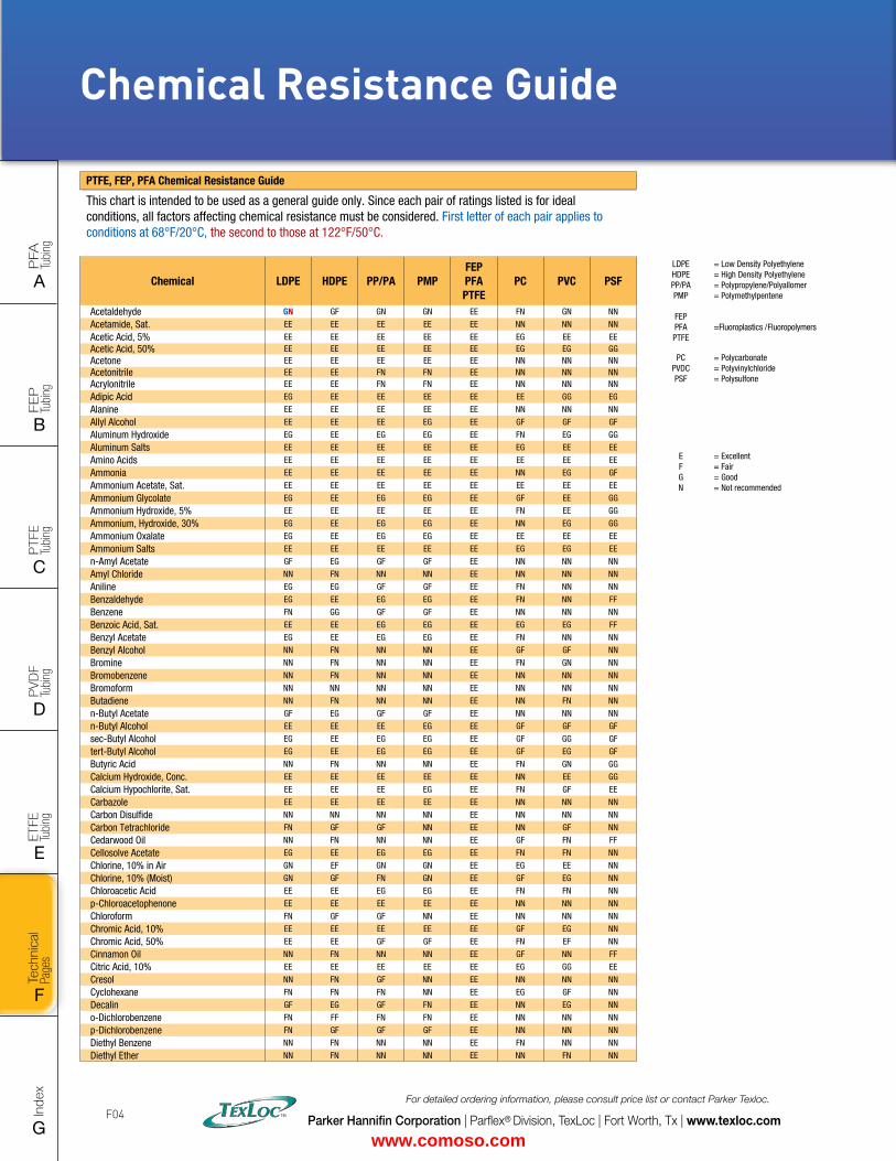
Intro
PFA
Tu
bing
A
FEP
Tu
bing
B
PVD
F
Tubi
ng
D
PTFE
Tu
bing
C
Index
G
Tech
nica
l Pa
ges
F
ETFE
Tu
bing
E
Parker Hannifin Corporation | Parflex® Division, TexLoc | Fort Worth, Tx | www.texloc.com
For detailed ordering information, please consult price list or contact Parker Texloc.
F04
LDPE HDPEPP/PAPMP
= Low Density Polyethylene = High Density Polyethylene = Polypropylene/Polyallomer = Polymethylpentene
FEP PFA PTFE
=Fluoroplastics /Fluoropolymers
PC PVDC PSF
= Polycarbonate = Polyvinylchloride = Polysulfone
E FGN
= Excellent = Fair = Good = Not recommended
Chemical Resistance Guide
PTFE, FEP, PFA Chemical Resistance Guide
This chart is intended to be used as a general guide only. Since each pair of ratings listed is for ideal conditions, all factors affecting chemical resistance must be considered. First letter of each pair applies to conditions at 68°F/20°C, the second to those at 122°F/50°C.
Chemical LDPE HDPE PP/PA PMPFEPPFAPTFE
PC PVC PSF
Acetaldehyde GN GF GN GN EE FN GN NN
Acetamide, Sat. EE EE EE EE EE NN NN NN
Acetic Acid, 5% EE EE EE EE EE EG EE EEAcetic Acid, 50% EE EE EE EE EE EG EG GGAcetone EE EE EE EE EE NN NN NNAcetonitrile EE EE FN FN EE NN NN NNAcrylonitrile EE EE FN FN EE NN NN NN
Adipic Acid EG EE EE EE EE EE GG EG
Alanine EE EE EE EE EE NN NN NN
Allyl Alcohol EE EE EE EG EE GF GF GF
Aluminum Hydroxide EG EE EG EG EE FN EG GG
Aluminum Salts EE EE EE EE EE EG EE EE
Amino Acids EE EE EE EE EE EE EE EE
Ammonia EE EE EE EE EE NN EG GF
Ammonium Acetate, Sat. EE EE EE EE EE EE EE EE
Ammonium Glycolate EG EE EG EG EE GF EE GG
Ammonium Hydroxide, 5% EE EE EE EE EE FN EE GG
Ammonium, Hydroxide, 30% EG EE EG EG EE NN EG GG
Ammonium Oxalate EG EE EG EG EE EE EE EE
Ammonium Salts EE EE EE EE EE EG EG EE
n-Amyl Acetate GF EG GF GF EE NN NN NN
Amyl Chloride NN FN NN NN EE NN NN NN
Aniline EG EG GF GF EE FN NN NN
Benzaldehyde EG EE EG EG EE FN NN FF
Benzene FN GG GF GF EE NN NN NN
Benzoic Acid, Sat. EE EE EG EG EE EG EG FF
Benzyl Acetate EG EE EG EG EE FN NN NN
Benzyl Alcohol NN FN NN NN EE GF GF NN
Bromine NN FN NN NN EE FN GN NN
Bromobenzene NN FN NN NN EE NN NN NN
Bromoform NN NN NN NN EE NN NN NN
Butadiene NN FN NN NN EE NN FN NN
n-Butyl Acetate GF EG GF GF EE NN NN NN
n-Butyl Alcohol EE EE EE EG EE GF GF GF
sec-Butyl Alcohol EG EE EG EG EE GF GG GF
tert-Butyl Alcohol EG EE EG EG EE GF EG GF
Butyric Acid NN FN NN NN EE FN GN GG
Calcium Hydroxide, Conc. EE EE EE EE EE NN EE GG
Calcium Hypochlorite, Sat. EE EE EE EG EE FN GF EE
Carbazole EE EE EE EE EE NN NN NN
Carbon Disulfide NN NN NN NN EE NN NN NN
Carbon Tetrachloride FN GF GF NN EE NN GF NN
Cedarwood Oil NN FN NN NN EE GF FN FF
Cellosolve Acetate EG EE EG EG EE FN FN NN
Chlorine, 10% in Air GN EF GN GN EE EG EE NN
Chlorine, 10% (Moist) GN GF FN GN EE GF EG NN
Chloroacetic Acid EE EE EG EG EE FN FN NN
p-Chloroacetophenone EE EE EE EE EE NN NN NN
Chloroform FN GF GF NN EE NN NN NN
Chromic Acid, 10% EE EE EE EE EE GF EG NN
Chromic Acid, 50% EE EE GF GF EE FN EF NN
Cinnamon Oil NN FN NN NN EE GF NN FF
Citric Acid, 10% EE EE EE EE EE EG GG EE
Cresol NN FN GF NN EE NN NN NN
Cyclohexane FN FN FN NN EE EG GF NN
Decalin GF EG GF FN EE NN EG NN
o-Dichlorobenzene FN FF FN FN EE NN NN NN
p-Dichlorobenzene FN GF GF GF EE NN NN NN
Diethyl Benzene NN FN NN NN EE FN NN NN
Diethyl Ether NN FN NN NN EE NN FN NN
www.comoso.com
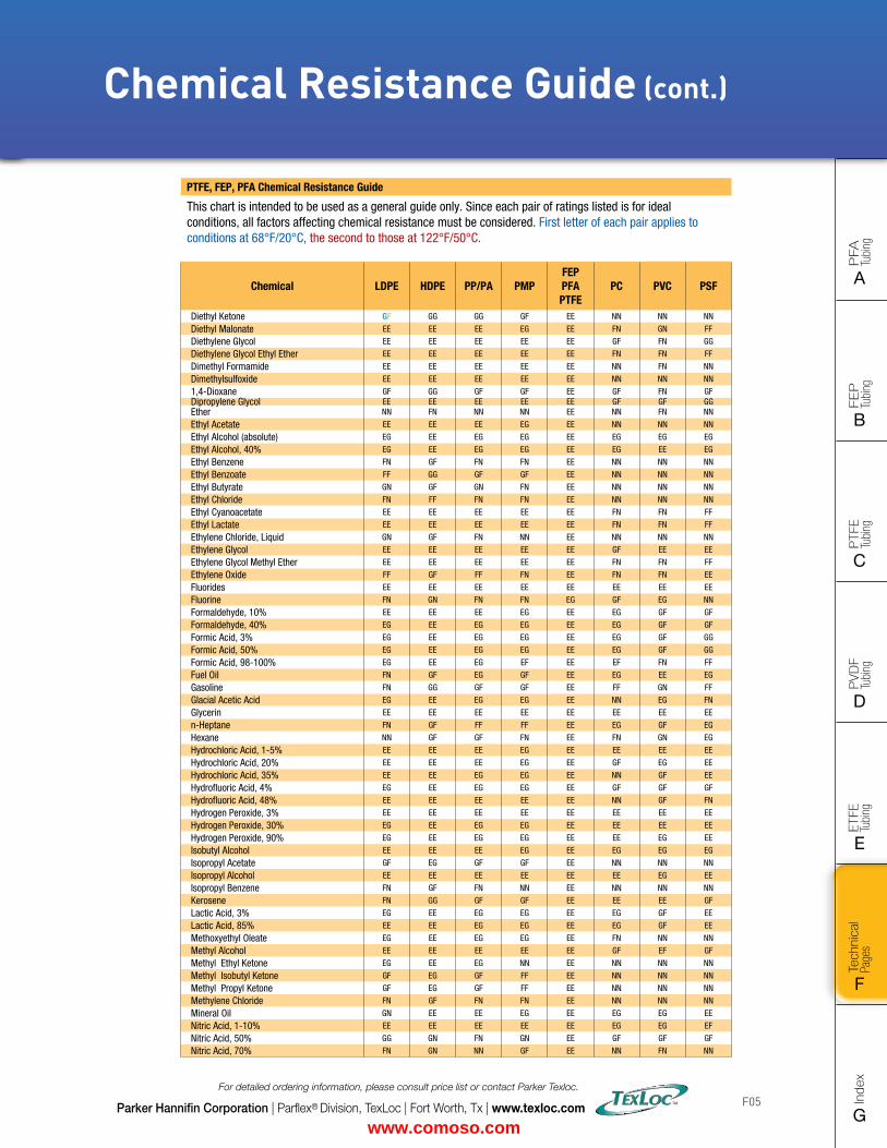
FLAT SIZE – 8.5" X 11" (11 x 17 spreads to be separated during final gather)CUT SIZE – 8.5" X 11"BLEED SIZE – 8.75” X 11.25”FINISHINGS – Drill holes
Intro
PFA
Tu
bing
A
FEP
Tu
bing
B
PVD
F
Tubi
ng
D
PTFE
Tu
bing
C
Index
G
Tech
nica
l Pa
ges
F
ETFE
Tu
bing
E
Parker Hannifin Corporation | Parflex® Division, TexLoc | Fort Worth, Tx | www.texloc.com
For detailed ordering information, please consult price list or contact Parker Texloc.
F05
Chemical Resistance Guide (cont.)
PTFE, FEP, PFA Chemical Resistance Guide
This chart is intended to be used as a general guide only. Since each pair of ratings listed is for ideal conditions, all factors affecting chemical resistance must be considered. First letter of each pair applies to conditions at 68°F/20°C, the second to those at 122°F/50°C.
Chemical LDPE HDPE PP/PA PMPFEPPFAPTFE
PC PVC PSF
Diethyl Ketone GF GG GG GF EE NN NN NN
Diethyl Malonate EE EE EE EG EE FN GN FF
Diethylene Glycol EE EE EE EE EE GF FN GG
Diethylene Glycol Ethyl Ether EE EE EE EE EE FN FN FF
Dimethyl Formamide EE EE EE EE EE NN FN NN
Dimethylsulfoxide EE EE EE EE EE NN NN NN
1,4-Dioxane GF GG GF GF EE GF FN GFDipropylene Glycol EE EE EE EE EE GF GF GGEther NN FN NN NN EE NN FN NN
Ethyl Acetate EE EE EE EG EE NN NN NN
Ethyl Alcohol (absolute) EG EE EG EG EE EG EG EG
Ethyl Alcohol, 40% EG EE EG EG EE EG EE EG
Ethyl Benzene FN GF FN FN EE NN NN NN
Ethyl Benzoate FF GG GF GF EE NN NN NN
Ethyl Butyrate GN GF GN FN EE NN NN NN
Ethyl Chloride FN FF FN FN EE NN NN NN
Ethyl Cyanoacetate EE EE EE EE EE FN FN FF
Ethyl Lactate EE EE EE EE EE FN FN FF
Ethylene Chloride, Liquid GN GF FN NN EE NN NN NN
Ethylene Glycol EE EE EE EE EE GF EE EE
Ethylene Glycol Methyl Ether EE EE EE EE EE FN FN FF
Ethylene Oxide FF GF FF FN EE FN FN EE
Fluorides EE EE EE EE EE EE EE EE
Fluorine FN GN FN FN EG GF EG NN
Formaldehyde, 10% EE EE EE EG EE EG GF GF
Formaldehyde, 40% EG EE EG EG EE EG GF GF
Formic Acid, 3% EG EE EG EG EE EG GF GG
Formic Acid, 50% EG EE EG EG EE EG GF GG
Formic Acid, 98-100% EG EE EG EF EE EF FN FF
Fuel Oil FN GF EG GF EE EG EE EG
Gasoline FN GG GF GF EE FF GN FF
Glacial Acetic Acid EG EE EG EG EE NN EG FN
Glycerin EE EE EE EE EE EE EE EE
n-Heptane FN GF FF FF EE EG GF EG
Hexane NN GF GF FN EE FN GN EG
Hydrochloric Acid, 1-5% EE EE EE EG EE EE EE EE
Hydrochloric Acid, 20% EE EE EE EG EE GF EG EE
Hydrochloric Acid, 35% EE EE EG EG EE NN GF EE
Hydrofluoric Acid, 4% EG EE EG EG EE GF GF GF
Hydrofluoric Acid, 48% EE EE EE EE EE NN GF FN
Hydrogen Peroxide, 3% EE EE EE EE EE EE EE EE
Hydrogen Peroxide, 30% EG EE EG EG EE EE EE EE
Hydrogen Peroxide, 90% EG EE EG EG EE EE EG EE
Isobutyl Alcohol EE EE EE EG EE EG EG EG
Isopropyl Acetate GF EG GF GF EE NN NN NN
Isopropyl Alcohol EE EE EE EE EE EE EG EE
Isopropyl Benzene FN GF FN NN EE NN NN NN
Kerosene FN GG GF GF EE EE EE GF
Lactic Acid, 3% EG EE EG EG EE EG GF EE
Lactic Acid, 85% EE EE EG EG EE EG GF EE
Methoxyethyl Oleate EG EE EG EG EE FN NN NN
Methyl Alcohol EE EE EE EE EE GF EF GF
Methyl Ethyl Ketone EG EE EG NN EE NN NN NN
Methyl Isobutyl Ketone GF EG GF FF EE NN NN NN
Methyl Propyl Ketone GF EG GF FF EE NN NN NN
Methylene Chloride FN GF FN FN EE NN NN NN
Mineral Oil GN EE EE EG EE EG EG EE
Nitric Acid, 1-10% EE EE EE EE EE EG EG EF
Nitric Acid, 50% GG GN FN GN EE GF GF GF
Nitric Acid, 70% FN GN NN GF EE NN FN NN
www.comoso.com
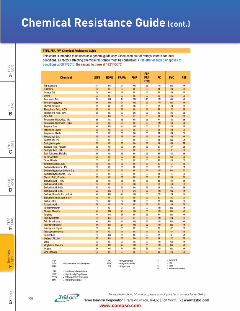
Intro
PFA
Tu
bing
A
FEP
Tu
bing
B
PVD
F
Tubi
ng
D
PTFE
Tu
bing
C
Index
G
Tech
nica
l Pa
ges
F
ETFE
Tu
bing
E
FEP PFA PTFE
=Fluoroplastics /Fluoropolymers
LDPE HDPEPP/PAPMP
= Low Density Polyethylene = High Density Polyethylene = Polypropylene/Polyallomer = Polymethylpentene
PC PVDC PSF
= Polycarbonate = Polyvinylchloride = Polysulfone
Parker Hannifin Corporation | Parflex® Division, TexLoc | Fort Worth, Tx | www.texloc.com
For detailed ordering information, please consult price list or contact Parker Texloc.
F06
Chemical Resistance Guide (cont.)
PTFE, FEP, PFA Chemical Resistance Guide
This chart is intended to be used as a general guide only. Since each pair of ratings listed is for ideal conditions, all factors affecting chemical resistance must be considered. First letter of each pair applies to conditions at 68°F/20°C, the second to those at 122°F/50°C.
Chemical LDPE HDPE PP/PA PMPFEPPFAPTFE
PC PVC PSF
Nitrobenzene NN FN NN NN EE NN NN NN
n-Octane EE EE EE EE EE GF FN GF
Orange Oil FN GF GF FF EE FF FN FF
Ozone EG EE EG EE EE EG EG EE
Perchloric Acid GN GN GN GN GF NN GN NN
Perchloroethylene NN NN NN NN EE NN NN NN
Phenol, Crystals GN GF GN FG EE EN FN FF
Phosphoric Acid, 1-5% EE EE EE EE EE EE EE EE
Phosphoric Acid, 85% EE EE EG EG EE EG EG EE
Pine Oil GN EG EG GF EE GF FN FF
Potassium Hydroxide, 1% EE EE EE EE EE FN EE EE
Potassium Hydroxide, Conc. EE EE EE EE EE NN EG EE
Propane Gas NN FN NN NN EE FN EG FF
Propylene Glycol EE EE EE EE EE GF FN GG
Propylene Oxide EG EE EG EG EE GF FN GG
Resorcinol, Sat. EE EE EE EE EE GF FN NN
Resorcinol, 5% EE EE EE EE EE GF GN NN
Salicylaldehyde EG EE EG EG EE GF FN FF
Salicylic Acid, Powder EE EE EE EG EE EG GF EE
Salicylic Acid, Sat. EE EE EE EE EE EG GF EE
Salt Solutions, Metallic EE EE EE EE EE EE EE EE
Silver Acetate EE EE EE EE EE EG GG EE
Silver Nitrate EG EE EG EE EE EE EG EE
Sodium Acetate, Sat. EE EE EE EE EE EG GF EE
Sodium Hydroxide, 1% EE EE EE EE EE FN EE EE
Sodium Hydroxide,50% to Sat. GG EE EE EE EE NN NN EG
Sodium Hypochlorite, 15% EE EE EE EE EE GF EE EE
Stearic Acid, Crystals EE EE EE EE EE EG EG GG
Sulfuric Acid, 1-6% EE EE EE EE EE EE EG EE
Sulfuric Acid, 20% EE EE EG EG EE EG EG EE
Sulfuric Acid, 60% EG EE EG EG EE GF EG EE
Sulfuric Acid, 98% GG GG FN GG EE NN GN NN
Sulfuric Dioxide, Liq., 46psi NN FN NN NN EE GN FN GG
Sulfuric Dioxide, wet or dry EE EE EE EE EE EG EG GG
Sulfur Salts FN GF FN FN EE FN NN GG
Tartaric Acid EE EE EE EE EE EG EG EE
Tetrahydrofuran FN GF GF FF EE NN NN NN
Thionyl Chloride NN NN NN NN EE NN NN NN
Toluene FN GG GF FF EE FN NN NN
Tributyl Citrate GF EG GF GF EE NN FN FF
Trichloroethane NN FN NN NN EE NN NN NN
Trichloroethylene NN FN NN NN EE NN NN NN
Triethylene Glycol EE EE EE EE EE EG GF EE
Tripropylene Glycol EE EE EE EE EE EG GF EE
Turpentine FN GG GF FF EE FN GF NN
Undecyl Alcohol EF EG EG EG EE GF EF FF
Urea EE EE EE EG EE NN GN NN
Vinylidene Chloride NN FN NN NN EE NN NN NN
Xylene GN GF FN FN EE NN NN NN
Zinc Stearate EE EE EE EE EE EE EG EE
E FGN
= Excellent = Fair = Good = Not recommended
www.comoso.com
Intro
PFA
Tu
bing
A
FEP
Tu
bing
B
PVD
F
Tubi
ng
D
PTFE
Tu
bing
C
Index
G
Tech
nica
l Pa
ges
F
ETFE
Tu
bing
E
Parker Hannifin Corporation | Parflex® Division, TexLoc | Fort Worth, Tx | www.texloc.com
For detailed ordering information, please consult price list or contact Parker Texloc.
F08
Parker Safety GuideFor selecting and using Hose, Tubing, Fittings, and Related Accessories
! Parker Safety Guide for Selecting and Using Hose, Tubing, Fittings and Related AccessoriesPublication No. 4400-B.1 Revised: November 2007
WARNING: Failure or improper selection or improper use of hose, tubing, fittings, assemblies or related accessories (“Products”) can cause death, personal injury and property damage. Possible consequences of failure or im-proper selection or improper use of these Products include but are not limited to:
• Fittings thrown off at high speed.• High velocity fluid discharge.• Explosion or burning of the conveyed fluid.• Electrocution from high voltage electric powerlines.• Contact with suddenly moving or falling objects that are controlled by
the conveyed fluid.
• Injections by high-pressure fluid discharge.• Dangerously whipping Hose.• Contact with conveyed fluids that may be hot, cold, toxic or otherwise
injurious.• Sparking or explosion caused by static electricity buildup or other
sources of electricity.• Sparking or explosion while spraying paint or flammable liquids.• Injuries resulting from inhalation, ingestion or exposure to fluids.
Before selecting or using any of these Products, it is important that you read and follow the instructions below. Only Hose from Parker’s Stratoflex Products Division is approved for in flight aerospace applications.
1.0 GENERAL INSTRUCTIONS1.1 Scope: This safety guide provides instructions for selecting and using (including assembling, installing, and maintaining) these Products. For convenience, all rubber and/or thermoplastic products commonly called “hose” or “tubing” are called “Hose” in this safety guide. All as-semblies made with Hose are called “Hose Assemblies”. All products commonly called “fittings”, “couplings” or “adapters” are called “Fittings”. All related accessories (including crimping and swaging machines and tooling) are called “Related Accessories”. This safety guide is a supple-ment to and is to be used with the specific Parker publications for the specific Hose, Fittings and Related Accessories that are being considered for use. Parker publications are available at www.parker.com. SAE J1273 (www.sae.org) and ISO 17165 2 (www.ans i .org) a lso pro -vide recommended practices for hydraul ic Hose Assemblies.
1.2 Fail-Safe: Hose, Hose Assemblies and Fittings can and do fail without warning for many reasons. Design all systems and equipment in a fail safe mode, so that failure of the Hose, Hose Assembly or Fi t t ing wi l l not endanger persons or property.
1.3 Distribution: Provide a copy of this safety guide to each person re-sponsible for selecting or using Hose and Fitting products. Do not select or use Parker Hose or Fittings without thoroughly reading and understanding this safety guide as well as the specific Parker publications for the Products. 1.4 User Responsibility: Due to the wide variety of operating conditions and applications for Hose and Fittings, Parker does not represent or warrant that any particular Hose or Fitting is suitable for any specific end use system. This safety guide does not analyze all technical parameters that must be considered in selecting a product. The user, through its own analysis and testing, is solely responsible for: • Making the final selection of the Products. • Assuring that the user’s requirements are met and that the application
presents no health or safety hazards. • Providing all appropriate health and safety warnings on the equipment
on which the Products are used. • Assuring compliance with all applicable government and industry standards.
1.5 Additional Questions: Call the appropriate Parker technical service department if you have any questions or require any additional information. See the Parker publication for the Products being considered or used, or call 1 800 CPARKER, or go to www.parker.com, for telephone numbers of the appropriate technical service department.
2.0 HOSE AND FITTING SELECTION INSTRUCTIONS2.1 Electrical Conductivity: Certain applications require that the Hose be nonconductive to prevent electrical current flow. Other applications require the Hose and the Fittings and the Hose/Fitting interface to be sufficiently conductive to drain off static electricity. Extreme care must be exercised
when selecting Hose and Fittings for these or any other applications in which electrical conductivity or nonconductivity is a factor.The electrical conductivity or nonconductivity of Hose and Fittings is depen-dent upon many factors and may be susceptible to change. These factors include but are not limited to the various materials used to make the Hose and the Fittings, Fitting finish (some Fitting finishes are electrically conductive while others are nonconductive), manufacturing methods (including moisture control), how the Fittings contact the Hose, age and amount of deterioration or damage or other changes, moisture content of the Hose at any particular time, and other factors.The following are considerations for electrically nonconductive and conductive Hose. For other applications consult the individual catalog pages and the appropriate industry or regulatory standards for proper selection.
2.1.1 Electrically Nonconductive Hose: Certain applications require that the Hose be nonconductive to prevent electrical current flow or to maintain electrical isolation. For applications that require Hose to be electrically nonconductive, including but not limited to applications near high voltage electric lines, only special nonconductive Hose can be used. The manufac-turer of the equipment in which the nonconductive Hose is to be used must be consulted to be certain that the Hose and Fittings that are selected are proper for the application. Do not use any Parker Hose or Fittings for any such application requiring nonconductive Hose, including but not limited to applications near high voltage electric lines, unless (i) the application is expressly approved in the Parker technical publication for the product, (ii) the Hose is marked “nonconductive”, and (iii) the manufacturer of the equipment on which the Hose is to be used specifically approves the particular Parker Hose and Fittings for such use.
2.1.2 Electrically Conductive Hose: Parker manufactures special Hose for certain applications that require electrically conductive Hose.Parker manufactures special Hose for conveying paint in airless paint spray-ing applications. This Hose is labeled “Electrically Conductive Airless Paint Spray Hose” on its layline and packaging. This Hose must be properly con-nected to the appropriate Parker Fittings and properly grounded in order to dissipate dangerous static charge buildup, which occurs in all airless paint spraying applications. Do not use any other Hose for airless paint spraying, even if electrically conductive. Use of any other Hose or failure to properly connect the Hose can cause a fire or an explosion resulting in death, personal injury, and property damage.Parker manufactures a special Hose for certain compressed natural gas (“CNG”) applications where static electricity buildup may occur. Parker CNG Hose assemblies comply with the requirements of ANSI/IAS NGV 4.2-1999; CSA 12.52-M99, “Hoses for Natural Gas Vehicles and Dispensing Systems” (www.ansi.org). This Hose is labeled “Electrically Conductive for CNG Use” on its layline and packaging. This Hose must be properly connected to the appropriate Parker Fittings and properly grounded in order to dissipate dangerous static charge buildup, which occurs in, for example, high velocity
www.comoso.com
FLAT SIZE – 8.5" X 11" (11 x 17 spreads to be separated during final gather)CUT SIZE – 8.5" X 11"BLEED SIZE – 8.75” X 11.25”FINISHINGS – Drill holes
Intro
PFA
Tu
bing
A
FEP
Tu
bing
B
PVD
F
Tubi
ng
D
PTFE
Tu
bing
C
Index
G
Tech
nica
l Pa
ges
F
ETFE
Tu
bing
E
Parker Hannifin Corporation | Parflex® Division, TexLoc | Fort Worth, Tx | www.texloc.com
For detailed ordering information, please consult price list or contact Parker Texloc.
F09
2.2 Pressure: Hose selection must be made so that the published maximum working pressure of the Hose and Fittings are equal to or greater than the maximum system pressure. The maximum working pressure of a Hose Assembly is the lower of the respective published maximum working pres-sures of the Hose and the Fittings used. Surge pressures or peak transient pressures in the system must be below the published maximum working pressure for the Hose. Surge pressures and peak pressures can usually only be determined by sensitive electrical instrumentation that measures and indicates pressures at millisecond intervals. Mechanical pressure gauges indicate only average pressures and cannot be used to determine surge pressures or peak transient pressures. Published burst pressure ratings for Hose is for manufacturing test purposes only and is no indica-tion that the Product can be used in applications at the burst pressure or otherwise above the published maximum recommended working pressure.
2.3 Suction: Hoses used for suction applications must be selected to insure that the Hose will withstand the vacuum and pressure of the system. Improperly selected Hose may collapse in suction application.
2.4 Temperature: Be certain that fluid and ambient temperatures, both steady and transient, do not exceed the limitations of the Hose. Tempera-tures below and above the recommended limit can degrade Hose to a point where a failure may occur and release fluid. Properly insulate and protect the Hose Assembly when routing near hot objects (e.g. manifolds). Do not use any Hose in any application where failure of the Hose could result in the conveyed fluids (or vapors or mist from the conveyed fluids) contact-ing any open flame, molten metal, or other potential fire ignition source that could cause burning or explosion of the conveyed fluids or vapors.
2.5 Fluid Compatibility: Hose Assembly selection must assure com-patibility of the Hose tube, cover, reinforcement, and Fittings with the fluid media used. See the fluid compatibility chart in the Parker pub-lication for the product being considered or used. This information is offered only as a guide. Actual service life can only be determined by the end user by testing under all extreme conditions and other analysis. Hose that is chemically compatible with a particular fluid must be as-sembled using Fittings and adapters containing likewise compatible seals.
2.6 Permeation: Permeation (that is, seepage through the Hose) will occur from inside the Hose to outside when Hose is used with gases, liquid and gas fuels, and refrigerants (including but not limited to such materials as helium, diesel fuel, gasoline, natural gas, or LPG). This permeation may result in high concentrations of vapors which are potentially flammable, explosive, or toxic, and in loss of fluid. Dangerous explosions, fires, and other hazards can result when using the wrong Hose for such applications. The system designer must take into account the fact that this permeation will take place and must not use Hose if this permeation could be hazardous. The system designer must take into account all legal, government, insurance, or any other special regulations which govern the use of fuels and refrigerants. Never use a Hose even though the fluid compatibility is acceptable without considering the potential hazardous effects that can result from permeation through the Hose Assembly.
Permeation of moisture from outside the Hose to inside the Hose will also occur in Hose assemblies, regardless of internal pressure. If this moisture perme-ation would have detrimental effects (particularly, but not limited to refrigeration and air conditioning systems), incorporation of sufficient drying capacity in the system or other appropriate system safeguards should be selected and used.
2.7 Size: Transmission of power by means of pressurized flu-id varies with pressure and rate of flow. The size of the compo-nents must be adequate to keep pressure losses to a minimum and avoid damage due to heat generation or excessive fluid velocity.
2.8 Routing: Attention must be given to optimum routing to minimize inherent problems (kinking or flow restriction due to Hose collapse, twisting of the Hose, proximity to hot objects or heat sources). For additional rout-ing recommendations see SAE J1273 and ISO 17165-2. Hose Assemblies have a finite life and if possible, should be installed in a manner that allows for ease of inspection and future replacement. Rubber Hose because of its relative short life, should not be used in residential and commercial buildings for HVAC (heating, ventilating and air conditioning) applications.
2.9 Environment: Care must be taken to insure that the Hose and Fittings are either compatible with or protected from the environment (that is, surrounding conditions) to which they are exposed. Environmental conditions including but not limited to ultraviolet radiation, sunlight, heat, ozone, moisture, water, salt wa-ter, chemicals and air pollutants can cause degradation and premature failure. 2.10 Mechanical Loads: External forces can significantly reduce Hose life or cause failure. Mechanical loads which must be considered include excessive flexing, twist, kinking, tensile or side loads, bend radius, and vibration. Use of swivel type Fittings or adapters may be required to insure no twist is put into the Hose. Unusual applications may require special testing prior to Hose selection.
2.11 Physical Damage: Care must be taken to protect Hose from wear, snag-ging, kinking, bending smaller that minimum bend radius and cutting, any of which can cause premature Hose failure. Any Hose that has been kinked or bent to a radius smaller than the minimum bend radius, and any Hose that has been cut or is cracked or is otherwise damaged should be removed and discarded.
2.12 Proper End Fitting: See instructions 3.2 through 3.5. These recom-mendations may be substantiated by testing to industry standards such as SAE J517 for hydraulic applications, or MIL-A-5070, AS1339, or AS3517 for Hoses from Parker’s Stratoflex Products Division for aerospace applications.
2.13 Length: When establishing a proper Hose length, motion absorp-tion, Hose length changes due to pressure, and Hose and machine toler-ances and movement must be considered.
2.14 Specifications and Standards: When selecting Hose and Fittings, government, industry, and Parker specifications and recommendations must be reviewed and followed as applicable.
2.15 Hose Cleanliness: Hose components may vary in cleanliness levels. Care must be taken to insure that the Hose Assembly selected has an adequate level of cleanliness for the application.
2.16 Fire Resistant Fluids: Some fire resistant fluids that are to be conveyed by Hose require use of the same type of Hose as used with petroleum base fluids. Some such fluids require a special Hose, while a few fluids will not work with any Hose at all. See instructions 2.5 and 1.5. The wrong Hose may fail af-ter a very short service. In addition, all liquids but pure water may burn fiercely under certain conditions, and even pure water leakage may be hazardous.
2.17 Radiant Heat: Hose can be heated to destruction without contact by such nearby items as hot manifolds or molten metal. The same heat source may then initiate a fire. This can occur despite the presence of cool air around the Hose.
2.18 Welding or Brazing: When using a torch or arc welder in close proxim-ity to hydraulic lines, the hydraulic lines should be removed or shielded with appropriate fire resistant materials. Flame or weld spatter could burn through the Hose and possibly ignite escaping fluid resulting in a catastrophic failure. Heating of plated parts, including Hose Fittings and adapters, above 450°F (232°C) such as during welding, brazing or soldering may emit deadly gases.
Safety GuideCNG dispensing or transfer. Do not use any other Hose for CNG applications where static charge buildup may occur, even if electrically conductive. Use of other Hoses in CNG applications or failure to properly connect or ground this Hose can cause a fire or an explosion resulting in death, personal injury, and property damage. Care must also be taken to protect against CNG permeation through the Hose wall. See section 2.6, Permeation, for more information. Parker CNG Hose is intended for dispenser and vehicle use at a maximum temperature of 180°F (82°C). Parker CNG Hose should not be used in confined spaces or unventilated areas or areas exceeding 180°F (82°C). Final assemblies must be tested for leaks. CNG Hose Assemblies should be tested on a monthly basis for conductivity per ANSI/IAS NGV 4.2-1999; CSA 12.52-M99.Parker manufactures special Hose for aerospace in flight applications. Aerospace in flight applications employing Hose to transmit fuel, lubricating fluids and hydraulic fluids require a special Hose with a conductive inner tube. This Hose for in flight applications is available only from Parker’s Stratoflex Products Division. Do not use any other Parker Hose for in flight applications, even if electrically conductive. Use of other Hoses for in flight applications or failure to properly connect or ground this Hose can cause a fire or an explosion resulting in death, personal injury and property damage. These Hose assemblies for in flight applications must meet all applicable aerospace industry, aircraft engine and aircraft requirements.
www.comoso.com
Intro
PFA
Tu
bing
A
FEP
Tu
bing
B
PVD
F
Tubi
ng
D
PTFE
Tu
bing
C
Index
G
Tech
nica
l Pa
ges
F
ETFE
Tu
bing
E
Parker Hannifin Corporation | Parflex® Division, TexLoc | Fort Worth, Tx | www.texloc.com
For detailed ordering information, please consult price list or contact Parker Texloc.
F10
2.19 Atomic Radiation: Atomic radiation affects all materials used in Hose assemblies. Since the long-term effects may be unknown, do not expose Hose assemblies to atomic radiation. 2.20 Aerospace Applications: The only Hose and Fittings that may be used for in flight aerospace applications are those available from Parker’s Stratoflex Products Division. Do not use any other Hose or Fittings for in flight applications. Do not use any Hose or Fittings from Parker’s Strato-flex Products Division with any other Hose or Fittings, unless expressly approved in writing by the engineering manager or chief engineer of Stratoflex Products Division and verified by the user’s own testing and inspection to aerospace industry standards.
2.21 Unlocking Couplings: Ball locking couplings or other Fittings with quick disconnect ability can unintentionally disconnect if they are dragged over obstructions, or if the sleeve or other disconnect member, is bumped or moved enough to cause disconnect. Threaded Fittings should be considered where there is a potential for accidental uncoupling.
3.0 HOSE AND FITTING ASSEMBLY AND INSTALLATION INSTRUCTIONS3.1 Component Inspection: Prior to assembly, a careful examination of the Hose and Fittings must be performed. All components must be checked for correct style, size, catalog number, and length. The Hose must be examined for cleanliness, obstructions, blisters, cover looseness, kinks, cracks, cuts or any other visible defects. Inspect the Fitting and sealing surfaces for burrs, nicks, corrosion or other imperfections. Do NOT use any component that displays any signs of nonconformance.3.2 Hose and Fitting Assembly: Do not assemble a Parker Fitting on a Parker Hose that is not specifically listed by Parker for that Fitting, unless authorized in writing by the engineering manager or chief engineer of the appropriate Parker division. Do not assemble a Parker Fitting on another manufacturer’s Hose or a Parker Hose on another manufacturer’s Fitting unless (i) the engineering manager or chief engineer of the appropriate Parker division approves the Assembly in writing or that combination is expressly approved in the appropriate Parker literature for the specific Parker product, and (ii) the user verifies the Assembly and the application through analysis and testing. For Parker Hose that does not specify a Parker Fitting, the user is solely responsible for the selection of the proper Fitting and Hose Assembly procedures. See instruction 1.4.To prevent the possibility of problems such as leakage at the Fitting or sys-tem contamination, it is important to completely remove all debris from the cutting operation before installation of the Fittings. The Parker published instructions must be followed for assembling the Fittings on the Hose. These instructions are provided in the Parker Fitting catalog for the specific Parker Fitting being used, or by calling 1 800 CPARKER, or at www.parker.com.
3.3 Related Accessories: Do not crimp or swage any Parker Hose or Fitting with anything but the listed swage or crimp machine and dies in accordance with Parker published instructions. Do not crimp or swage another manufac-turer’s Fitting with a Parker crimp or swage die unless authorized in writing by the engineering manager or chief engineer of the appropriate Parker division.
3.4 Parts: Do not use any Parker Fitting part (including but not limited to socket, shell, nipple, or insert) except with the correct Parker mating parts, in accordance with Parker published instructions, unless authorized in writing by the engineering manager or chief engineer of the appropriate Parker division.
3.5 Field Attachable/Permanent: Do not reuse any field attachable Hose Fitting that has blown or pulled off a Hose. Do not reuse a Parker permanent Hose Fitting (crimped or swaged) or any part thereof. Com-plete Hose Assemblies may only be reused after proper inspection under section 4.0. Do not assemble Fittings to any previously used hydraulic Hose that was in service, for use in a fluid power application.
3.6 Pre-Installation Inspection: Prior to installation, a careful examina-tion of the Hose Assembly must be performed. Inspect the Hose As-sembly for any damage or defects. DO NOT use any Hose Assembly that displays any signs of nonconformance.
3.7 Minimum Bend Radius: Installation of a Hose at less than the mini-mum listed bend radius may significantly reduce the Hose life. Particular
attention must be given to preclude sharp bending at the Hose to Fitting juncture. Any bending during installation at less than the minimum bend radius must be avoided. If any Hose is kinked during installation, the Hose must be discarded. 3.8 Twist Angle and Orientation: Hose Assembly installation must be such that relative motion of machine components does not produce twisting. 3.9 Securement: In many applications, it may be necessary to restrain, protect, or guide the Hose to protect it from damage by unnecessary flex-ing, pressure surges, and contact with other mechanical components. Care must be taken to insure such restraints do not introduce additional stress or wear points. 3.10 Proper Connection of Ports: Proper physical installation of the Hose Assembly requires a correctly installed port connection insuring that no twist or torque is transferred to the Hose when the Fittings are being tightened or otherwise during use.. 3.11 External Damage: Proper installation is not complete without insuring that tensile loads, side loads, kinking, flattening, potential abrasion, thread damage or damage to sealing surfaces are corrected or eliminated. See instruction 2.10. 3.12 System Checkout: All air entrapment must be eliminated and the system pressurized to the maximum system pressure (at or below the Hose maximum working pressure) and checked for proper function and freedom from leaks. Personnel must stay out of potential hazardous areas while testing and using. 3.13 Routing: The Hose Assembly should be routed in such a manner so if a failure does occur, the escaping media will not cause personal injury or property damage. In addition, if fluid media comes in contact with hot sur-faces, open flame or sparks, a fire or explosion may occur. See section 2.4. 3.14 Ground Fault Equipment Protection Devices (GFEPDs): WARNING! Fire and Shock Hazard: To minimize the danger of fire if the heating cable of a Multitube bundle is damaged or improperly installed, use a Ground Fault Equipment Protection Device. Electrical fault currents may be insufficient to trip a conventional circuit breaker.For ground fault protection, the IEEE 515:1989 (www.ansi.org) standard for heating cables recommends the use of GFEPDs with a nominal 30 milliam-pere trip level for “piping systems in classified areas, those areas requiring a high degree of maintenance, or which may be exposed to physical abuse or corrosive atmospheres”.
4.0 HOSE AND FITTING MAINTENANCE AND REPLACEMENT INSTRUCTIONS4.1 Even with proper selection and installation, Hose life may be significantly reduced without a continuing maintenance program. The severity of the ap-plication, risk potential from a possible Hose failure, and experience with any Hose failures in the application or in similar applications should determine the frequency of the inspection and the replacement for the Products so that Products are replaced before any failure occurs. A maintenance program must be established and followed by the user and, at minimum, must include instructions 4.2 through 4.7. 4.2 Visual Inspection Hose/Fitting: Any of the following conditions require immediate shut down and replacement of the Hose Assembly: • Fitting slippage on Hose; • Damaged, cracked, cut or abraded cover (any reinforcement exposed); • Hard, stiff, heat cracked, or charred Hose; • Cracked, damaged, or badly corroded Fittings; • Leaks at Fitting or in Hose; • Kinked, crushed, flattened or twisted Hose; and • Blistered, soft, degraded, or loose cover. 4.3 Visual Inspection All Other: The following items must be tightened, repaired, corrected or replaced as required: • Leaking port conditions; • Excess dirt buildup; • Worn clamps, guards or shields; and
Safety Guide
www.comoso.com
FLAT SIZE – 8.5" X 11" (11 x 17 spreads to be separated during final gather)CUT SIZE – 8.5" X 11"BLEED SIZE – 8.75” X 11.25”FINISHINGS – Drill holes
Intro
PFA
Tu
bing
A
FEP
Tu
bing
B
PVD
F
Tubi
ng
D
PTFE
Tu
bing
C
Index
G
Tech
nica
l Pa
ges
F
ETFE
Tu
bing
E
Parker Hannifin Corporation | Parflex® Division, TexLoc | Fort Worth, Tx | www.texloc.com
For detailed ordering information, please consult price list or contact Parker Texloc.
F11
Safety Guide • System fluid level, fluid type, and any air entrapment. 4.4 Functional Test: Operate the system at maximum operating pressure and check for possible malfunctions and leaks. Personnel must avoid po-tential hazardous areas while testing and using the system. See section 2.2. 4.5 Replacement Intervals: Hose assemblies and elastomeric seals used on Hose Fittings and adapters will eventually age, harden, wear and deteriorate under thermal cycling and compression set. Hose Assemblies and elastomeric seals should be inspected and replaced at specific re-placement intervals, based on previous service life, government or industry recommendations, or when failures could result in unacceptable downtime, damage, or injury risk. See section 1.2. Hose and Fittings may be subjected to internal mechanical and/or chemical wear from the conveying fluid and may fail without warning. The user must determine the product life under such circumstances by testing. Also see section 2.5. See section 1.2.4.6 Hose Inspection and Failure: Hydraulic power is accomplished by utiliz-ing high pressure fluids to transfer energy and do work. Hoses, Fittings and Hose Assemblies all contribute to this by transmitting fluids at high pressures. Fluids under pressure can be dangerous and potentially lethal and, therefore, extreme caution must be exercised when working with fluids under pressure and handling the Hoses transporting the fluids. From time to time, Hose Assemblies will fail if they are not replaced at proper time intervals. Usually these failures are the result of some form of misapplication, abuse, wear or failure to perform proper maintenance. When Hoses fail, generally the high pressure fluids inside escape in a stream which may or may not be visible to the user. Under no circumstances should the user attempt to locate the leak by “feeling” with their hands or any other part of their body. High pressure fluids can and will penetrate the skin and cause severe tissue damage and possibly loss of limb. Even seemingly minor hydraulic fluid injection injuries must be treated immediately by a physician with knowledge of the tissue damaging properties of hydraulic fluid.If a Hose failure occurs, immediately shut down the equipment and leave the area until pressure has been completely released from the Hose Assembly. Simply shutting down the hydraulic pump may or may not eliminate the pres-sure in the Hose Assembly. Many times check valves, etc., are employed in a system and can cause pressure to remain in a Hose Assembly even when pumps or equipment are not operating. Tiny holes in the Hose, commonly known as pinholes, can eject small, dangerously powerful but hard to see streams of hydraulic fluid. It may take several minutes or even hours for the pressure to be relieved so that the Hose Assembly may be examined safely.Once the pressure has been reduced to zero, the Hose Assembly may be taken off the equipment and examined. It must always be replaced if a failure has occurred. Never attempt to patch or repair a Hose Assembly that has failed. Consult the nearest Parker distributor or the appropriate Parker division for Hose Assembly replacement information.Never touch or examine a failed Hose Assembly unless it is obvious that the Hose no longer contains fluid under pressure. The high pressure fluid is extremely dangerous and can cause serious and potentially fatal injury.
4.7 Elastomeric seals: Elastomeric seals will eventually age, harden, wear and deteriorate under thermal cycling and compression set. Elastomeric seals should be inspected and replaced. 4.8 Refrigerant gases: Special care should be taken when working with refrigeration systems. Sudden escape of refrigerant gases can cause blind-ness if the escaping gases contact the eye and can cause freezing or other severe injuries if it contacts any other portion of the body. 4.9 Compressed natural gas (CNG): Parker CNG Hose Assemblies should be tested after installation and before use, and at least on a monthly basis per ANSI/IAS NGV 4.2-1999; CSA 12.52-M99 Section 4.2 “Visual Inspection Hose/Fitting”. The recommended procedure is to pressurize the Hose and check for leaks and to visually inspect the Hose for damage.Caution: Matches, candles, open flame or other sources of ignition shall not be used for Hose inspection. Leak check solutions should be rinsed off after use.5.0 HOSE STORAGE5.1 Age Control: Hose and Hose Assemblies must be stored in a manner that facilitates age control and first-in and first-out usage based on manu-facturing date of the Hose and Hose Assemblies. The shelf life of rubber Hose or Hose Assemblies that have passed visual inspection and a proof test is 10 years (40 quarters) from the date of manufacture. The shelf life of thermoplastic and polytetrafluoroethylene Hose or Hose Assemblies is considered to be unlimited. 5.2 Storage: Stored Hose and Hose Assemblies must not be subjected to damage that could reduce their expected service life and must be placed in a cool, dark and dry area with the ends capped. Stored Hose and Hose Assemblies must not be exposed to temperature extremes, ozone, oils, cor-rosive liquids or fumes, solvents, high humidity, rodents, insects, ultraviolet light, electromagnetic fields or radioactive materials.
www.comoso.com
Intro
PFA
Tu
bing
A
FEP
Tu
bing
B
PVD
F
Tubi
ng
D
PTFE
Tu
bing
C
Index
G
Tech
nica
l Pa
ges
F
ETFE
Tu
bing
E
Parker Hannifin Corporation | Parflex® Division, TexLoc | Fort Worth, Tx | www.texloc.com
For detailed ordering information, please consult price list or contact Parker Texloc.
F12
Offer of SaleThe items described in this document and other documents or descriptions provided by Parker Hannifin Corporation, as subsidiaries and its authorized distributors are hereby offered for sale at prices to be established by Parker Hannifin Corporation, its subsidiaries and its authorized distributors. This offer and its acceptance by any customer (“Buyer”) shall be governed by all of the following Terms and Conditions. Buyer’s order for any such item, when communicated to Parker Hannifin Corporation, its subsidiary or an authorized distributor (“Seller”) verbally or in writing, shall constitute acceptance of this offer.
1. Terms and Conditions of Sale: All descriptions, quotations, proposals, offers, acknowledgments, acceptances and sales of Seller’s products are subject to and shall be governed exclusively by the terms and conditions stated herein. Buyer’s acceptance of any offer to sell is limited to these terms and conditions. Any terms or conditions in addition to, or inconsistent with those stated herein, proposed by Buyer in any acceptance of an offer by Seller, are hereby objected to. No such additional, different or inconsistent terms and conditions shall become part of the contract between Buyer and Seller unless expressly accepted in writing by Seller. Seller’s acceptance of any offer to purchase by Buyer is expressly conditional upon Buyer’s assent to all the terms and conditions stated herein, including any terms in addition to, or inconsistent with those contained in Buyer’s offer. Acceptance of Seller’s products shall in all events constitute such assent.
2. Payment: Payment shall be made by Buyer net 30 days from the date of delivery of the items purchased hereunder. Any claims by Buyer for omissions or shortages in a shipment shall be waived unless Seller receives notice thereof within 30 days after Buyer’s receipt of the shipment.
3. Delivery: Unless otherwise provided on the face hereof, delivery shall be made F.O.B. Seller’s plant. Regardless of the method of delivery, however, risk of loss shall pass to Buyer upon Seller’s delivery to a carrier. Any delivery dates shown are approximate only and Seller shall have no liability for any delays in delivery.
4. Warranty: Seller warrants that the items sold thereunder shall be free from defects in material or workmanship for a period of 365 days from the date of shipment to Buyer, or 2,000 hours of use, whichever expires first. THIS WARRANTY COMPRISES THE SOLE AND ENTIRE WARRANTY PERTAINING TO ITEMS PROVIDED HEREUNDER. SELLER MAKES NO OTHER WARRANTY, GAURANTEE, OR REPRESENTATION OF ANY KIND WHATSOEVER. ALL OTHER WARRANTIES, INCLUDING BUT NOT LIMITED TO, MERCHANTIBILITY AND FITNESS FOR PURPOSE, WHETHER EXPRESS, IMPLIED, OR ARISING BY OPERATION OF LAW, TRADE USAGE, OR COURSE OF DEALING ARE HEREBY DISCLAIMED.
NOTWITHSTANDING THE FOREGOING, THERE ARE NO WARRANTIES WHATSOEVER ON ITEMS BUILT OR ACQUIRED WHOLELY OR PARTIALLY, TO BUYER’S DESIGNS OR SPECIFICATIONS.
5. Limitation Of Remedy: SELLER’S LIABILITY ARISING FROM OR IN ANY WAY CONNECTED WITH THE ITEMS SOLD OR THIS CONTRACT SHALL BE LIMITED EXCLUSIVELY TO REPAIR OR REPLACEMENT OF THE ITEMS SOLD OR REFUND OF THE PURCHASE PRICE PAID BY BUYER, AT SELLER’S SOLE OPTION. IN NO EVENT SHALL SELLER BE LIABLE FOR ANY INCIDENTAL, CONSEQUENTIAL OR SPECIAL DAMAGES OF ANY KIND OR NATURE WHATSOEVER, INCLUDING BUT NOT LIMITED TO LOST PROFITS ARISING FROM OR IN ANY WAY CONNECTED WITH THIS AGREEMENT OR ITEMS SOLD HEREUNDER, WHETHER ALLEGED TO ARISE FROM BREACH OF CONTRACT, EXPRESS OR IMPLIED WARRANTY, OR IN TORT, INCLUDING WITHOUT LIMITATION, NEGLIGENCE, FAILURE TO WARN OR STRICT LIABILITY.
6. Changes, Reschedules and Cancellations: Buyer may request to modify the designs or specifications for the items sold herunder as well as the quantities and delivery dates thereof, or may request to cancel all or part of this order, however, no such requested modification or cancellation shall become part of the contract between Buyer and Seller unless accepted by Seller in a written amendment to this Agreement. Acceptance of any such requested modification or cancellation shall be at Seller’s discretion, and shall be upon such terms and conditions as Seller may require.
7. Special Tooling: A tooling charge may be imposed for any special tooling, including without limitation, dies, fixtures, molds and patterns, acquired to manufacture items sold pursuant to this contract. Such special tooling shall be and remain Seller’s property notwithstanding payment of any charges by
Buyer. In no event will Buyer acquire any interest in apparatus belonging to Seller which is utilized in the manufacture of the items sold hereunder, even if such apparatus has been specially converted or adapted for such manufacture and notwithstanding any charges paid by Buyer. Unless otherwise agreed, Seller shall have the right to alter, discard or otherwise dispose of any special tooling or other property in its sole discretion at any time.
8. Buyer’s Property: Any designs, tools, patterns, materials, drawings, confidential information or equipment furnished by Buyer or any other items which become Buyer’s property, may be considered obsolete and may be destroyed by Seller after two (2) consecutive years have elapsed without Buyer placing an order for the items which are manufactured using such property. Seller shall not be responsible for any loss or damage to such property while it is in Seller’s possession or control.
9. Taxes: Unless otherwise indicated on the face hereof, all prices and charges are exclusive of excise, sales, use, property, occupational or like taxes which may be imposed by any taxing authority upon the manufacture, sale or delivery of the items sold hereunder. If any such taxes must be paid by Seller of if Seller is liable for the collection of such tax, the amount thereof shall be in additon to the amounts for the items sold. Buyer agrees to pay all such taxes or to reimburse Seller therefore upon receipt of its invoice. If Buyer claims exemption from any sales, use or other tax imposed by any taxing authority, Buyer shall save Seller harmless from and against any such tax, together with any interest or penalties thereon which may be assessed if the items are held to be taxable.
10. Indemnity For Infringement of Intellectual Property Rights: Seller shall have no liability for infringement of any patents, trademarks, copyrights, trade dress, trade secrets or similar rights except as provided in this Part 10. Seller will defend and indemnify Buyer against allegations of infringement of U.S. patents, U.S. trademarks, copyrights, trade dress and trade secrets (hereinafter “Intellectual Property Rights”). Seller will defend at its expense and will pay the cost of any settlement or damages awarded in an action brought against Buyer based on an allegation that an item sold pursuant to this contract infringes in the Intellectual Property Rights of a third party. Seller’s obligation to defend and indemnify Buyer is contingent on Buyer notifying Seller within ten (10) days after Buyer becomes aware of such allegations of infringement, and Seller having sole control over the defense of any allegations or actions including all negotiations for settlement or compromise. If an item sold hereunder is subject to a claim that it infringes the Intellectual Property Rights of a third party, Seller may, at its sole expense and options, procure for Buyer the right to continue using said item, replace or modify said item so as to make it noninfringing, or offer to accept return of said item and return the purchase price less a reasonable allowance for depreciation. Notwithstanding the foregoing, Seller shall have no liability for claims of infringement based on information provided by Buyer, or directed to items delivered hereunder for which the designs are specified in whole or part by Buyer, or infringements resulting from the modification, combination or use in a system of any item sold hereunder. The foregoing provisions of this Part 10 shall constitute Seller’s sole and exclusive liability and Buyer’s sole and exclusive remedy for infringement of Intellectual Property Rights.
If a claim is based on information provided by Buyer or if the design for an item delivered hereunder is specified in whole or in part by Buyer, Buyer shall defend and indemnify Seller for all costs, expenses or judgments resulting from any claim that such item infriges any patent, trademark, copyright, trade dress, trade secret or any similiar right.
11. Force Majeure: Seller does not assume the risk of and shall not be liable for delay or failure to perform any of Seller’s obligations by reason of circumstances beyond the reasonable control of Seller (hereinafter “Events of Force Majeure”). Events of Force Majeure shall include without limitation, accidents, acts of God, strikes or labor disputes, acts, laws, rules or regulations of any government or government agency, fires, floods, delays or failures in delivery of carriers or suppliers, shortages of materials and any other cause beyond Seller’s control.
12. Entire Agreement/Governing Law: The terms and conditions set forth herein, together with any amendments, modifications and any different terms or conditions expressly accepted by Seller in writing, shall constitute the entire Agreement concerning the items sold, and there are no oral or other representations or agreements which pertain thereto. This Agreement shall be governed in all respects by the law of the State of Ohio. No actions arising out of the sale of the items sold hereunder or this Agreement may be brought by either party more than two (2) years after the cause of action accrues.
5/14
www.comoso.com
Index by Part Number 101- ..........................................C02-C03103- ..........................................B02-B03104- .......................................... A04-A05105- .......................................... A02-A03110- ..........................................D02-D03111- ..........................................D02-D03
201- ..................................................C05203- ..................................................B03204- ..................................................A05205- ..................................................A03
703- ..................................................B16704- ..................................................B16 705- ..................................................B16
81914/1 ............................................C2881914/2 ............................................C2881914/3 ............................................B1281914/4 ............................................B1281914/5 ............................................ E0481914/6 ............................................ E04
CR03 ................................................B15 CV01 .................................................C25CV03 .................................................B11CVH01 ..............................................C27CVL01 ...............................................C27
HS1.25 ..............................................B08HS1.3 ................................................B04HS1.5 ................................................ E02HS1.67 ..............................................B06HS2TFI ..............................................C17HS2TFL ................................... C17, C21HS2TFS ................................... C17, C19HS2TFT ................................... C17, C20HS4TFI ..............................................C22
TFB ...................................................C13TFH ...................................................C09TFL ...................................................C12TFS ...................................................C10TFT ...................................................C11
TSSL .................................................B09TSSS ................................................B09TSWTF ..............................................C15
Intro
PFA
Tu
bing
A
FEP
Tu
bing
B
PVD
F
Tubi
ng
D
PTFE
Tu
bing
C
Index
G
Tech
nica
l Pa
ges
F
ETFE
Tu
bing
E
For detailed ordering information, please consult price list or contact Parker Texloc.
iParker Hannifin Corporation | Parflex® Division, TexLoc | Fort Worth, Tx | www.texloc.com
Technical Index
Chemical Resistance Summary ......... 13Chemical Resistance Guide ............. F04
Heat Shrink Temperatures ................... 9
Icon Identification ................................. 3
Material Feature Overview .................... 4
Offer of Sale ..................................... F11
Nomenclature - Smoothbore .............. 14Nomenclature - Convo/Corr ............... 14
Nomenclature - Heatshrink, Beading, Electrical Insulation ............................ 15
Property Comparison Convoluted ....... 7Property Comparison Resin ............. F03Property Comparison - Quick Ref ... F02
Safety Guide ..................................... F07Value Added Services......................... 11
We make Custom Tubing to your specifications
everyday.
Contact Customer Service for more information. 800.423.6551
Index by Keyword1.25:1 Heatshrink .................................9, B081.3:1 Heatshrink ...................................9, B041.67:1 Heatshrink .................................9, B06
AWG Heatshrink .......................................C18AWG Tubing..............................................C08Beading, PTFE ......................................5, C13
Cable Wrap ...............................................C14 Coiled Tubing .....................................10, B16Colortrax ....................................................... 5Conductive Tubing ....................................... 8Convoluted Tubing ...................6-7, B10-B13,
C24-C29, E04Convo-Flon ...........................................6, B10Convo-Tex® .........................................6, C24 Corrugated Tubing ..............................10, B14
Double Shrink ...........................................B09 ETFE ..................................4, 9, E01-E05, F02 Etching ....................................................... 11
FEP .......................................4, B01-B17, F02Flaring ......................................................... 11Flanging ...................................................... 11 Flex® Tubing .............................................D02Forming ...................................................... 11
Heat Shrink .......... 9, B04-B09, C16-C23, E02Heavy Wall Convoluted ........................6, C26Heavy Wall Heat Shrink ....................C16-C17Heavy Wall Tubing ...........A03, A05, B03, C04
C09, D03High Purity PFA .................... 4, A02-A03, F02
Industrial Wall Heat Shrink ............ C-22-C23, E02-E03
Industrial Wall Tubing ......A03, A05, B03, C03 D03
Light Wall Heatshrink ...... B09, C17, C18, C21Light Wall Tubing ..................... C06-C08, C12 Low Profile Convo ................................6, C26Metric Tubing ...................A03, A05, B03, C05
Paratubing .................................................. 10PFA ....................................... 4, A04-A05, F02 PFA, High Purity ................... 4, A02-A03, F02PTFE .....................................4, C01-C29, F02PVDF ....................................4, D01-D03, F02
Retractable Tubing .............................10, B16Rod, PTFE ............................................4, C13Roll Cover .............................................9, B08
Slitting ........................................................ 11Spaghetti Tubing ..............................C08-C12Spiral Wrap ...............................................C14Standard Wall Heat Shrink ...... B09, C16-C19Standard Wall Tubing .............. C06-C08, C10Superflex™ ..............................................D02
Thin Wall Heat Shrink .............. C16-C18, C20Thin Wall Tubing ...................... C06-C08, C11
Applications ................................................ 12
www.comoso.com

AerospaceKey MarketsAftermarket services Commercial transportsEnginesGeneral & business aviationHelicoptersLaunch vehiclesMilitary aircraftMissilesPower generation Regional transportsUnmanned aerial vehicles
Key ProductsControl systems & actuation productsEngine systems & componentsFluid conveyance systems& componentsFluid metering, delivery & atomization devicesFuel systems & componentsFuel tank inerting systemsHydraulic systems & componentsThermal managementWheels & brakes
AutomationKey Markets Alternative energyConveyor & material handlingFactory automationFood & beverageLife sciences & medicalMachine toolsPackaging machineryPaper machineryPlastics machinery Primary metalsSafety & securitySemiconductor & electronicsTransportation & automotive
Key Products AC/DC drives & systems Air preparationElectric actuators, gantryrobots & slidesHuman machine interfacesInvertersManifoldsMiniature fluidicsPneumatic actuators & grippersPneumatic valves & controlsRotary actuatorsStepper motors, servo motors,drives & controlsStructural extrusionsVacuum generators, cups & sensors
Fluid ConnectorsKey Markets Aerial liftAgricultureBulk chemical handlingConstruction machineryFood & beverageFuel & gas deliveryIndustrial machineryLife sciences MarineMiningMobileOil & gasRenewable energyTransportation
Key Products Check valves Connectors for low pressure fluid conveyanceDeep sea umbilicalsDiagnostic equipment Hose couplingsIndustrial hoseMooring systems & power cablesPTFE hose & tubing Quick couplingsRubber & thermoplastic hose Tube fittings & adaptersTubing & plastic fittings
HydraulicsKey Markets Aerial liftAgricultureAlternative energyConstruction machineryForestryIndustrial machineryMachine toolsMarineMaterial handlingMiningOil & gasPower generationRefuse vehiclesRenewable energyTruck hydraulicsTurf equipment
Key Products AccumulatorsCartridge valvesElectrohydraulic actuatorsHuman machine interfacesHybrid drivesHydraulic cylinders Hydraulic motors & pumpsHydraulic systemsHydraulic valves & controlsHydrostatic steeringIntegrated hydraulic circuitsPower take-offs Power unitsRotary actuatorsSensors
InstrumentationKey Markets Alternative fuelsBiopharmaceuticalsChemical & refiningFood & beverageMarine & shipbuildingMedical & dentalMicroelectronicsNuclear PowerOffshore oil explorationOil & gasPharmaceuticalsPower generationPulp & paperSteelWater/wastewater
Key ProductsAnalytical Instruments Analytical sample conditioningproducts & systemsChemical injection fittings& valvesFluoropolymer chemicaldelivery fittings, valves & pumpsHigh purity gas delivery fittings, valves, regulators& digital flow controllersIndustrial mass flow meters/controllersPermanent no-weld tube fittingsPrecision industrial regulators& flow controllersProcess control double block & bleedsProcess control fittings, valves, regulators & manifold valves
SealKey Markets AerospaceChemical processingConsumerFluid powerGeneral industrialInformation technologyLife sciencesMicroelectronicsMilitaryOil & gasPower generationRenewable energyTelecommunicationsTransportation
Key Products Dynamic sealsElastomeric o-ringsElectro-medical instrumentdesign & assembly EMI shieldingExtruded & precision-cut,fabricated elastomeric sealsHigh temperature metal sealsHomogeneous & insertedelastomeric shapesMedical device fabrication & assembly Metal & plastic retainedcomposite sealsShielded optical windowsSilicone tubing & extrusionsThermal managementVibration dampening
Parker’s Motion & Control Product GroupsAt Parker, we’re guided by a relentless drive to help our customers become more productive and achieve higher levels of profitabil-ity by engineering the best systems for their require-ments. It means looking at customer applications from many angles to find new ways to create value. What-ever the motion and control technology need, Parker has the experience, breadth of product and global reach to consistently deliver. No company knows more about motion and control technol-ogy than Parker. For further info call 1 800 C-Parker(1 800 272 7537).
Climate & Industrial ControlsKey Markets AgricultureAir conditioningConstruction MachineryFood & beverageIndustrial machineryLife sciencesOil & gasPrecision coolingProcessRefrigerationTransportation
Key Products AccumulatorsAdvanced actuatorsCO
2 controls
Electronic controllersFilter driersHand shut-off valvesHeat exchangers Hose & fittingsPressure regulating valvesRefrigerant distributorsSafety relief valvesSmart pumpsSolenoid valvesThermostatic expansion valves
FiltrationKey MarketsAerospaceFood & beverageIndustrial plant & equipmentLife sciencesMarineMobile equipmentOil & gasPower generation & renewable energyProcessTransportation Water Purification
Key Products Analytical gas generatorsCompressed air filters & dryersEngine air, coolant, fuel & oil filtration systemsFluid condition monitoring systemsHydraulic & lubrication filtersHydrogen, nitrogen & zero air generatorsInstrumentation filtersMembrane & fiber filtersMicrofiltrationSterile air filtrationWater desalination & purification filters & systems
www.comoso.com
Parker Hannifin CorporationParflex Division/TexLoc 4700 Lone Star Blvd.Fort Worth, TX 76106phone 817.625.5081 800.423.6551 fax 817.624.9095 800.438.9562 email: [email protected]
Your complete source for quality tube fittings, hose & hose fittings, brass & composite fittings, quick-disconnect couplings, valves and assembly tools, locally available from a worldwide network of authorized distributors.
Fittings:Available in inch and metric sizes covering SAE, BSP, DIN, GAZ, JIS and ISO thread configurations, manufactured from steel, stainless steel, brass, aluminum, nylon and thermoplastic.
Hose, Tubing and Bundles:Available in a wide variety of sizes and materials including rubber, wire-reinforced, thermoplastic, hybrid and custom compounds.
Worldwide Availability:Parker operates Fluid Connectors manufacturing locations and sales offices throughout North America, South America, Europe and Asia-Pacific.
For information, call toll free...
1-800-C-PARKER(1-800-272-7537)
Parker Fluid Connectors GroupNorth American Divisions & Distribution Service Centers
North American Divisions
Energy Products DivisionStafford, TXphone 281 566 4500fax 281 530 5353
Fluid System Connectors DivisionOtsego, MIphone 269 694 9411fax 269 694 4614
Hose Products DivisionWickliffe, OHphone 440 943 5700fax 440 943 3129
Industrial Hose DivisionStrongsville, OHphone 440 268 2120fax 440 268 2230
Parflex DivisionRavenna, OHphone 330 296 2871fax 330 296 8433
Quick Coupling DivisionMinneapolis, MNphone 763 544 7781fax 763 544 3418
Tube Fittings DivisionColumbus, OHphone 614 279 7070fax 614 279 7685
Distribution Service Centers
Buena Park, CAphone 714 522 8840fax 714 994 1183
Conyers, GAphone 770 929 0330fax 770 929 0230
Louisville, KYphone 502 937 1322fax 502 937 4180
Portland, ORphone 503 283 1020fax 503 283 2201
Toledo, OHphone 419 878 7000fax 419 878 7001fax 419 878 7420 (FCG Kit Operations)
CanadaGrimsby, ONTphone 905 945 2274fax 905 945 3945(Contact Grimsby for other Service Center locations.)
© 2014 Parker Hannifin Corporation - all rights reserved CAT 4150-55 GL 6/14
www.comoso.com