Embed Size (px)
Citation preview

FLUORESCENTNA MIKROSKOPIJA
Dr Milica MarkelićBiološki fakultet, Univerzitet u Beogradu

KONCEPT PREDAVANJA
Fluorescenca i fluorofore
Osnovni principi fluorescentne mikroskopije
Konfokalna VS. Konvencionalna Widefield fluorescentna mikroskopija
Principi konfokalne mikroskopije
Osnovni tipovi konfokalne mikroskopije
Laserska skenirajuća konfokalna mikroskopija (LSCM)
Modalitet dobijanja slike na konfokalnom mikroskopu
Biološke aplikacije konfokalne i fluorescentne mikroskopije
Fluorofore i tehnike fluorescentnog obeležavanja u mikroskopiji

Sir George Stokes, 1852.
ŠTA JE FLUORESCENCA?
FOTOLUMINISCENCIJA – apsorpcija i potom reradijacija (emisija)
svetlosti
• FOSFORESCENCIJA – ukoliko emisija svetlosti traje i do nekoliko
sekundi po prekidu ekscitacione energije (svetlosti)
• FLUORESCENCIJA – ukoliko emisija svetlosti traje samo tokom
apsorpcije ekscitacijskog (svetlosnog) zračenja

Vidljiva svetlost
Spektar elektromagnetnog zračenja
Što je talasna dužina veća to je energija zračenja niža.
Što je talasna dužina manja to je energija zračenja viša
Npr. opekotine od sunca izaziva UV zračenje a ne crvena vidljiva svetlost.
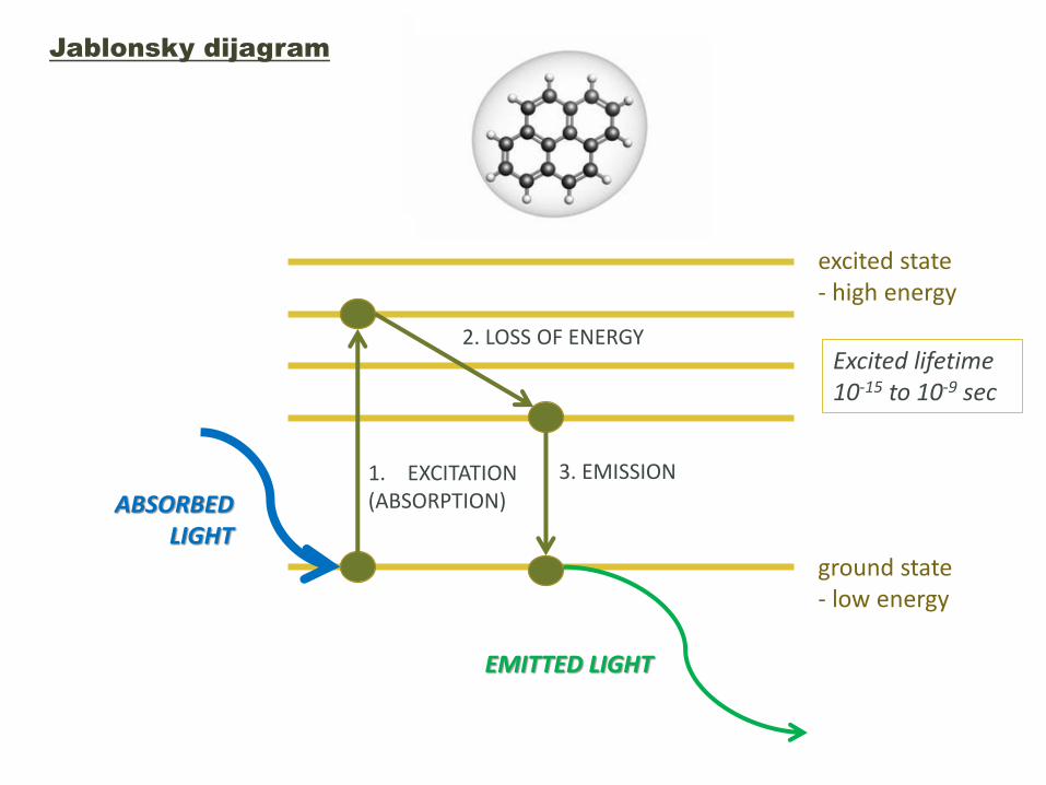
ground state- low energy
excited state- high energy
1. EXCITATION(ABSORPTION)
2. LOSS OF ENERGY
3. EMISSION
Excited lifetime10-15 to 10-9 sec
ABSORBED LIGHT
EMITTED LIGHT
Jablonsky dijagram

Single-photon ekscitacija Multi-photon ekscitacija
• KONVENCIONALNA FLUORESCENTNA
MIKROSKOPIJA
• KONVENCIONALNA KONFOKALNA
MIKROSKOPIJA
• MULTIFOTONSKA
MIKROSKOPIJA

SVOJSTVA FLUORESCENTNIH MOLEKULA (FLUOROFORA)
• Kvantni prinos – efikasnost fluorescentnog molekula da konvertuje apsorbovanu svetlost u emitovanu
Emisioni spektar NE zavisi od talasne dužine ekscitacijske svetlosti ali intenzitet emisije zavisi.
Štoksov pomeraj
Ekscitacijski spektarEmisioni spektar

Fotostabilna fluorofora Fotoizbeljena fluorofora
Definiše se kao ireverzibilna destrukcija pobuđene fluorofore
Kako izbeći/smanjiti fotoizbeljivanje?
Kraće osvetljivanje/skeniranje
Veće uveličanje i objektiv veće NA
Primena emisionih filtera sa širim opsegom propuštanja
Minimalni intenzitet ekscitacije
Primena “antifade” reagensa (ne na živim ćelijama!) – antioksidansi
– propil galat, hidrokvinon, p-fenilenediamin.
SVOJSTVA FLUOROFORA
Photobleaching

Lampa
Filter cube
Objektiv
uzorak
Kamera
OSNOVNI PRINCIPI FLUORESCENTNE MIKROSKOPIJE
WIDEFIELD EPI-FLUORESCENTNI MIKROSKOP
TRANS-ILUMINACIJA (dijaskopska iluminacija)
EPI-ILUMINACIJA(episkopska iluminacija)

CILJ - razdvajanje ekscitacijske od emitovane svetlosti
Objektiv je istovremeno i kondenzor
OSNOVNI PRINCIPI FLUORESCENTNE MIKROSKOPIJE
WIDEFIELD EPI-FLUORESCENTNI MIKROSKOP

FLUO LAMPA:
Hg, Xn, molibden-
halogenska, LED
EKSCITACIJSKI FILTER
EMISIONI FILTER
DIHROIČKO OGLEDALO
- Selekcija opsega ex. svetlosti
-razdvajanje pravog
signala od
background emisije
OSNOVNI PRINCIPI FLUORESCENTNE MIKROSKOPIJE
WIDEFIELD EPI-FLUORESCENTNI MIKROSKOP

FILTERI – „srce“ fluorescentnog mikroskopa
• long-pass filteri – propuštaju svu svetlost čija je talasna dužina
većaod određene a blokiraju sve ispod iste.
• short-pass filteri – suprotno od LP filtera • bandpass filteri – prpouštaju svetlost u okviru određenog opsega
• Dihroičko ogledalo (beam splitter) – reflektuje svetlost kraćih a
propušta svetlost većih talasnih dužina (od određene) – razdvajanje
ex. od em.svetlosti
Excitacijski filteri: X
Emisioni filteri: M
Beamsplitter: bs, dc, FT ("farb teiler“ – color splitter)
480/30 = centralna talasna dužina 450nm /opseg 30 nm [+/- 15]
BP, KP = bandpass, (BP 450-490)
LP = longpass filter- propušta sve iznad prikazane vrednosti (LP 500)
SP = shortpass filter - propušta sve ispod prikazane vrednosti

Transmisija
(%)
wave length (nm)
Ekscitacioni filter
Emisioni filter
Dihroičko ogl.
lampa
uzorak
kamera
Emisioni filter
Dihroičko ogledalo
Ekscitacioni filter
FILTERI – su spakovani u FILTER CUBES

Ekscitacija / emisija – izbor fluorofora
excitation and emission spectra of EGFP (green) and Cy5 (blue)
excitation and emission spectra of EGFP (green) and Cy2 (blue)
Nema filtera koji
može da razdvoji ove
talasne dužine!
Ex1 Ex2Em1 Em2

KONFOKALNA VS. WIDEFIELD FLUORESCENTNA MIKROSKOPIJA
KONFOKALNA MIKROSKOPIJA- Upotreba specifičnih talasnih dužina svetlosti (laser=- Eliminacija svetlosti van fokusa (pinhole)
Značajno povećana moć razlučivanja i kolokalizacije malih struktura i molekula uz visoku kontrastnost
FM ima brojne predosti zbog čega je u širokoj upotrebi ali i
nekoliko nedostataka:
Zamućenje
Bleed-through Photobleaching
- Biološke strukture su trodimenzionalne
- Widefield FM mikrografije debelih uzoraka imaju zamućen
izgled usled svetlosti sakupljene sa objekata iznad i ispod
fokalne ravni (van fokusa) – smanjenje kvaliteta slike

Widefield FM KM
MONOCHROMATIC
LIGHT
Kod KM osvetljava se samo mali deo uzorka, znatno manji nego kod konvencionalne FM.
- Kod KM ekscitacioni pinhole, fokalna ravan u uzorku i detektorski (emisioni) pinhole su u konjugovanim fokalnim ravnima –“konfokalni”- Zahvaljujući pinhole-u osvetljava se samo jedna tačka uzorka (u datom trenutku) umesto celog polja , što omogućava nastanak slika bez zamućenja


Patent Number: US003013467
PRINCIPI KONFOKALNE MIKROSKOPIJE
Marvin Minsky, 1955• Tipična widefield iluminacija se zamenjuje tačkastom iluminacijom
(zahvaljujući ekscitacijskom pinhole-u)• U put emitovane svetlosti umeće se apertura emisionog pinhole-a koja
omogućava prolazak i detekciju samo one svetlosti koja potiče iz fokalne tačke
• Svetlost koja se emituje iz osvetljene tačke se putem sočiva objektiva fokusira na malu tačku u ravni slike.
• Tačkasti izvor svetlosti je u konjugovanom fokusu na uzorku i u ravni slike – konfokalan (“u istom fokusu”)
• Uzorak se skenira tačkastim osvetljivanjem a informacija slike se sakuplja sekvencionalno – tačku po tačku (orig. pomeranjem postolja, danas –pomeranjem laserskog zraka)
• Slika uzorka se snima (orig. osciloskopski, danas – kompjuterski)
Moderni KM koriste sočivo objektiva i za fokusiranje osvetljenja i za fokusiranje slike –automatski to znači istu fokalnu ravan tj. konfokalnost.

KM su ušli u široku istraživačku upotrebu krajem 80-ih godina XX veka Tehnološka dostignuća koja su omogućila primenu Minskijevog konfokalnog dizajna:
1. Dovoljno jaki i stabilni laseri
2. Efikasno reflektujuća dihr.ogledala i precizniji filteri
3. Unapređenje metoda skeniranja i elektronike za detekciju slike
4.Fotodetektori visoke kvantne efikasnosti i niskog šuma
5. Unapređenje metoda pripreme uzoraka
6. Brzi računari sa mogućnošću obrade slike
7. Jednostavna software rešenja za analizu slike
8. Visoka rezolucija ekrana računara
9. Bioinformatičke tehnike manipulacije slikom
10. Mogućnost čuvanja velike količine elektronsih podataka
11. Sinteza fluorofora koje su bolje usklađene sa ekscitacijskom linijom lasera

Pošto se uzorak osvetljava tačku-po-tačku, a slika takođe dobija tačku-po-tačku, u datom trenutku se dobija samo slika jedne tačke uzorka. Da bi sedetektovala kompletna slika, potrebno je da se uzorak ili snop pomera.Moderni konfokalni mikroskopi – beam scanning mikroskopi
Point scanning CM – LSCM (Laser Scanning Confocal Microscope)
Multipoint (Area) scanning CM – Nipkow (spinning) Disk Confocal Microscope

Kako se formira slika?
Point Scanning Principle:
Scanning mirrors control
beam movement in X/Y
raster pattern - the image is
built up point by point in
each frame - RASTER SCAN
Each frame corresponds to a plane in the z-axis
– “OPTICAL SECTIONS” – no need to physically
slice up the specimen to reconstruct it in three
dimensions. Because light is used to image each
optical section, these will be in perfect register
and so can be reconstructed into a three-
dimensional model with ease.
Optical section Z-series
Beam diameter is limited by a pinhole aperture
>> field of illumination and detected signal are pointed
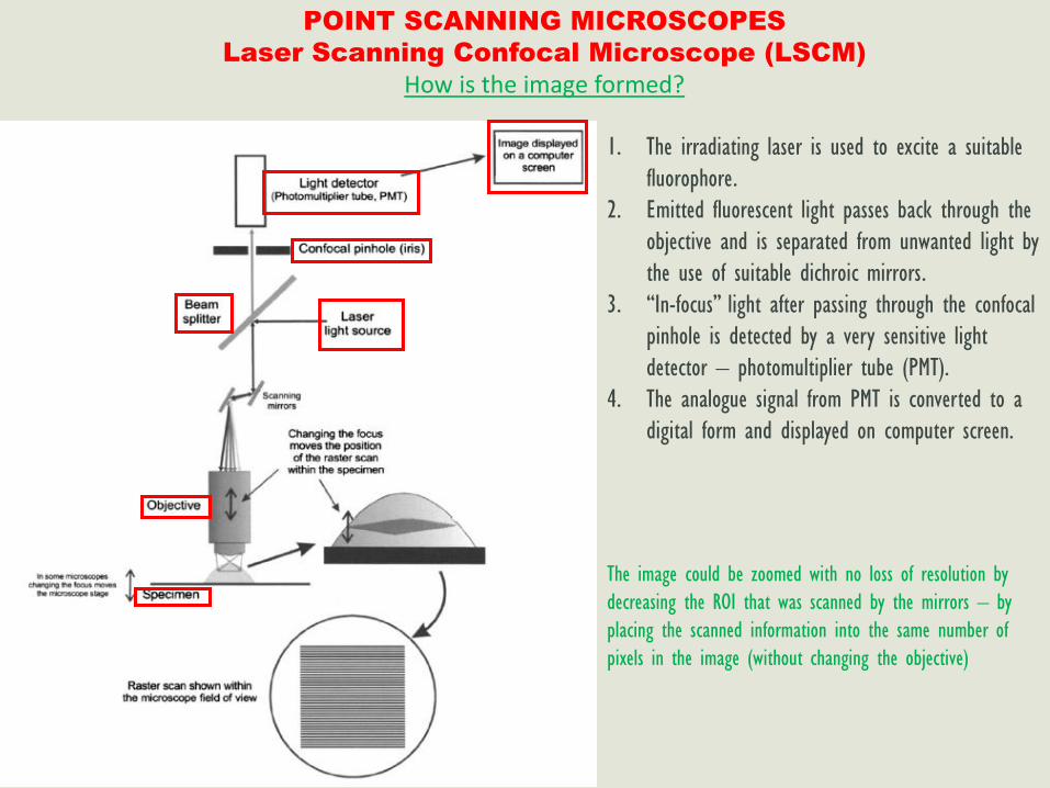
POINT SCANNING MICROSCOPES
Laser Scanning Confocal Microscope (LSCM)
How is the image formed?
1. The irradiating laser is used to excite a suitable
fluorophore.
2. Emitted fluorescent light passes back through the
objective and is separated from unwanted light by
the use of suitable dichroic mirrors.
3. “In-focus” light after passing through the confocal
pinhole is detected by a very sensitive light
detector – photomultiplier tube (PMT).
4. The analogue signal from PMT is converted to a
digital form and displayed on computer screen.
The image could be zoomed with no loss of resolution by
decreasing the ROI that was scanned by the mirrors – by
placing the scanned information into the same number of
pixels in the image (without changing the objective)

The thickness of the optical section could be adjusted simply by changing the diameter of a pinhole.
0.5 - 1.5 µm

POINT SCANNING MICROSCOPES
Laser Scanning Confocal Microscope (LSCM)
Optical Slicing
Optical section Z-series
At the heart of confocal microscopy is the ability to take
thin "optical slices" through the cell or tissue of interest.
- Great improvement of the image quality
- Great deal of information on:
• 3D structure of the object
• Subcellular location of the fluorescence
3D reconstruction
http://www.olympusfluoview.com/java/confocalvswidefield/index.html

POINT SCANNING MICROSCOPES
Laser Scanning Confocal Microscope (LSCM)
Components
Beam diameter is limited by a pinhole aperture
>> field of illumination and detected signal are pointed

POINT SCANNING MICROSCOPES
Laser Scanning Confocal Microscope (LSCM)
Components
1. LASERS – confocal light source
Fluo lamps are too weak for point confocal systems.
Strong bundled light is generated by LASERs (Light
Amplification by Stimulated Emission of Radiation).
There are different types of LASERs, gas lasers are
predominantly used:
• Argon ion
• Argon-Krypton
• Helium-Neon
LASER produces monochromatic light of a discrete
wavelength (“laser line”).
For the spectral range different LASERs are needed.
Depending on the microscope hardware, some of the
following lines might be available:

LSCM has many components including a
way for several different lasers to provide
excitation wavelengths and several
separate detectors for various emission
wavelengths
• Argon UV ArUV 351-364 nm
• Solid State Violet 405 nm
• Argon Ar 488-514 nm
• Krypton-Ar ArKr 488-568-648 nm
• Helium-Cad HeCd 442 nm
• Helium-Neon GreNe 543 nm
• Helium-Neon HeNe 633 nm


POINT SCANNING MICROSCOPES
Laser Scanning Confocal Microscope (LSCM)
Components
2. FILTERS – determine the spectral detection
CONVENTIONAL: COLORED GLASS FILTERS AND
DICHROIC MIRRORS
- Inexpensive
- Long useful lives
- Relatively insensitive to incidence light
- Low transmittance
- High autofluorescence at longer wavelenghts
MODERN: ACOUSTO-OPTICAL DEVICES – the adjustable
cristal filters
- AOTF (“excitation filter”)
- AOBS (“beam splitter”)


POINT SCANNING MICROSCOPES
Laser Scanning Confocal Microscope (LSCM)
Components
3. IMAGE DETECTORS – photomultiplier tubes (PMTs)
In confocal microscopy, fluorescence emission
is directed through a pinhole aperture
positioned near the image plane to exclude
light from fluorescent structures located
away from the objective focal plane, thus
reducing the amount of light available for
image formation.
As a result, the exceedingly low light levels
most often encountered in confocal
microscopy necessitate the use of highly
sensitive photon detectors that do not
require spatial discrimination, but instead
respond very quickly with a high level of
sensitivity to a continuous flux of varying
light intensity.PMTs contain a photosensitive surface that captures incident
photons and convert them into electrons which are then
multiplied – signal amplification
PMTs measure intensity without spectral information resulting in
the grayscale images

512x512
1024x1024
2048x2048
More pixels:
• smoother looking image - more xy information
• more light exposure of specimen
• larger file size
• slower imaging (less temporal resolution)

LUT
– Look Up Table


PMT1 – Channel 1
PMT2 – Channel 2
PMT3 – Channel 3
Merge

The detector signals are adjusted by gain and offset such that maximum number of grey level is included in the
resulting image (output).
•Gain: Amplifies the input signal by multiplication which results in a higher gray level value; bright features are
brought closer to saturation, general image brightness is increased.
•Offset: sets the gray level of a selected background to zero volts; adjust the darkest features in the image to black.
37
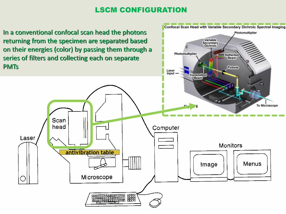
CLSM microscope
antivibration table
LSCM CONFIGURATION
In a conventional confocal scan head the photons returning from the specimen are separated based on their energies (color) by passing them through a series of filters and collecting each on separate PMTs

LSCM CONFIGURATION
Completely integrated electronic system

Svetlost iluminatora prolazi kroz seriju pinhole-a uređene distribucije na disku. Rotiranjem diska vrši se rasterizacija i emitovana svetlost koja se vraća kroz otvore na disku će biti konfokalna. Otvori na disku (pinhole-i) služe i kao tačkasti izvori svetlosti i kao konfokalne aperture – tj. i kao ekscitacijski i kao emisioni pinhole.
MULTIPOINT SCANNING MIKROSKOPI
Nipkow (spinning) disk konfokalni mikroskop

PREDNOSTI:1) Brzina – više tačaka se osvetljuje
istovremeno.2) Fotonska efikasnost CCD kamere3) Pogodno za žive uzorke – manja snaga
lasera4) Različiti izvori svetlosti mogući5) Može da se ugradi na već postojeći FM
NEDOSTACI:1) Mala efikasnost – potrebna jaka
iluminacija i jak fluorescentni signal2) Malo vidno polje3) Crosstalk između susednih pinhola –
ograničava debljinu uzorka4) Nije moguća upotreba visoko-osetljivih
detektora poput PMT5) Kompromis između rezolucije i
ukupnog signala
MULTIPOINT SCANNING MIKROSKOPI
Nipkow (spinning) disk konfokalni mikroskop

CONFOCAL IMAGING MODES
• FLUORESCENCE IMAGING MODES
o SINGLE OPTICAL SECTIONS
o Z-SERIES AND 3-D IMAGING
o TIME-LAPSE AND LIVE CELL IMAGING
o MULTIDIMENSIONAL IMAGING
o X-Z IMAGING
o SPECTRAL IMAGING
• REFLECTED LIGHT IMAGING MODE
• TRANSMITED LIGHT IMAGING MODE
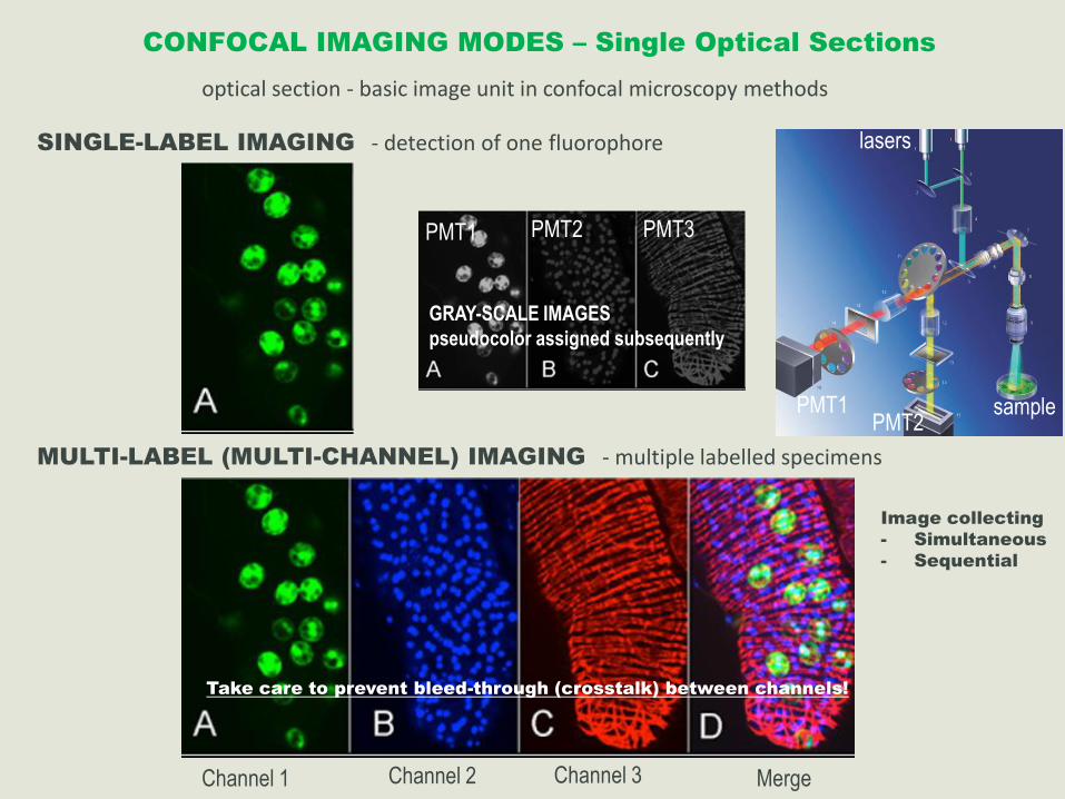
CONFOCAL IMAGING MODES – Single Optical Sections
optical section - basic image unit in confocal microscopy methods
SINGLE-LABEL IMAGING - detection of one fluorophore
MULTI-LABEL (MULTI-CHANNEL) IMAGING - multiple labelled specimens
Channel 1 Channel 2 Channel 3 Merge
Image collecting
- Simultaneous
- Sequential
GRAY-SCALE IMAGES
pseudocolor assigned subsequently
PMT1 PMT2 PMT3
Take care to prevent bleed-through (crosstalk) between channels!
PMT2PMT1
lasers
sample
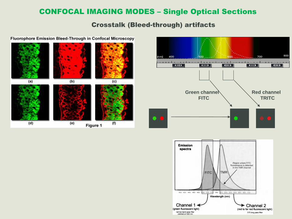
CONFOCAL IMAGING MODES – Single Optical Sections
Crosstalk (Bleed-through) artifacts
Green channel
FITC
Red channel
TRITC

Crosstalk
How to reduce:
• Use better separated fluorochromes
• Put the weak signal in the ‘left-handed’ channel
• Sequential imaging rather than simultaneous imaging
How to test:
• Turn off laser line for the ‘left-handed’ fluorochrome
Crosstalk (Bleed-through) artifacts
CONFOCAL IMAGING MODES – Single Optical Sections

Spectral properties of the available dyes limit the experimental freedom.
Often it is even difficult to clearly separate two fluorescence markers.
With more markers, the problem grows increasingly complex.
Cross-talk between the FP variants at the excitation and emisson level
Crosstalk (Bleed-through) artifacts
CONFOCAL IMAGING MODES – Single Optical Sections

CONFOCAL IMAGING MODES – Z-series and 3-D reconstruction
Z-series (Z-stack) – series of optical sections taken along the
z-axis
- collected by coordinating step-by-step changes in the fine
focus of the microscope with sequential image acquisition
at each step
- computer-controlled stepping motor that changes focus by
predetermined increments
Important parameters for Z-series acquisition:
• Specimen preparation – 3-D distortions
• Image registration – specimen movements,
misaligned filter sets
• Pixel resolution (“voxel”) – too few or too many
optical sections
• Image storage – large storage space

CONFOCAL IMAGING MODES – Z-series and 3-D reconstruction
y
x
z
x-y
x-z
y-z
X-Z and Y-Z imaging

CONFOCAL IMAGING MODES – Time-lapse and Live Samples Imaging
Live imaging principal benefit – ability to observe events in cells or
tissue as they happen.
Live samples are usually examined in a time-lapse mode: image
selection at pre-selected time intervals, images are placed into a
single file, usually viewed as a movie.
Imaging living samples with the LSCM is substantially more difficult
than imaging fixed specimens, and is not always a practical option
because the specimen may not tolerate the conditions involved.
Extreme care must be taken to keep your sample alive and
healthy
Schmitz M. et al. Nature Cell Biology 12, 886–93 (2010)

CONFOCAL IMAGING MODES – Multidimensional Imaging
Z-series of the same living sample are taken at periodic intervals over time and reconstructed 3-dimensionally - 4-D imaging
(3-D stereo movies or projections over time)
Collection of multichannel images as Z-series over time – 5-D imaging
Applications:
- Analysis of embryonic development
- Tracing cell lineages
- Imaging rapid cellular processes (signal pathways, ion fluctuations…)
t

CONFOCAL IMAGING MODES – Spectral Imaging
(spectral fingerprinting, lambda stack, lambda scan)
http://www.microscopyu.com/tutorials/flash/spectralimaging/lambdastack/index.html
- a region of interest in the x-y dimension (optical section) is examined along the wavelength axis to determine how pixel intensity and/or color changes due to signal level variations at different emission bands (λ planes)
- A series of images within a user-defined wavelength range is recorded – each image will be recorded at a
specific emission wavelength
- Applications:
- Measurement of the emission spectrum of new fluorophores,
- Determination of the emission maximum of a fluorophore in a specific sample to optimize detection,
- Detection of autofluorescence(s) where the spectrum can be unknown

CONFOCAL IMAGING MODES – Reflected and Transmitted Light Imaging
Reflected (Backscattered) Light Imaging Transmitted Light Imaging
RL imaging DF imaging BF imaging
- Probes that reflect light (nanogold, silver particles)
- collagen
- Bright field
- Phase contrast,
- Differential interference contrast (DIC),
- Dark field
A transmitted light detector is used to collect light passing
through the specimen, and a fiber optic light guide transmits the
signal to one of the PMTs in the microscope system's scan head
The transmitted light images and confocal epifluorescence
images can be acquired simultaneously using the same
illumination beam, ensuring that all of the images are in
registration. When the images are combined or merged using
image processing software, the precise location of labeled cells
within the tissues can be mapped.
Bright field
Dark field
Phase contrast
DIC

LSCM MEASURING TECHNIQUES
• DEPTH AND THICKNESS MEASUREMENTS
• FLUORESCENCE INTENSITY MEASUREMENTS
- CLSM software, Image J, FIJI…
- calibration is necessary!
- controls are necessary!
• CO-LOCALIZATION MEASUREMENTS
• SPECIAL MEASURING TECHNIQUES
• FRET
• FLIM
• FRAP
• …

CLSM MEASURING TECHNIQUES – Co-localization
Co-localization - presence of two or more different
molecules residing at the same physical location in a
specimen.
- Widely used to determine the relationships between
various macromolecules and subcellular structures
- In the context of digital imaging, the term refers to
colors emitted by fluorescent molecules sharing the
same pixel (voxel) in the image.
- Accurate c-olocalization analysis is only possible if
the fluorescence emission spectra are sufficiently
well separated between fluorophores and the correct
filter sets (or spectral slit widths) are using during the
acquisition sequence.
The ability to determine co-localization in a confocal microscope is
limited by the resolution of the optical system and the wavelength of
light used to illuminate the specimen.
- theoretical resolution of approximately 200 nm,
- in practice, this number drops to a value between 400 and 600
nm for a variety of reasons (misalignment of the microscope,
refractive index fluctuations, optical aberrations, and improper
specimen preparation).
- Co-localization is difficult to interpret
In almost all cases, however, the optical resolution limit of a
perfectly tuned confocal microscope is not sufficient to determine
whether two fluorescent molecules are attached to a single target,
or whether they even reside within the same organelle.
Software Analysis of Colocalization
The degree of fluorophore colocalization in a specimen is measured
by comparing color values for the equivalent pixel position in each
of the acquired images – scatterplot (fluorogram)
microtubules/mitochondria/nuclei co-localization maskscatterplot merge
ROI - indicates threshold levels of signal to be included
in the analysis
Co-localization does not mean interaction!

SPECIAL MEASURING TECHNIQUES – FRET
Förster (Fluorescence) Resonance Energy Transfer
- Measurements of protein-protein interactions inside cells
- Two fluorophores: emission of the first one (the donor) serves as the excitation
source for the second one (the acceptor) – resonance energy transfer
- FRET only occurs when the donor and the acceptor molecules are extremely close to one another, at a distance less than 100 Å or (preferable 20-50 Å)
- In this way, sub-resolution molecular measurements are made

SPECIAL MEASURING TECHNIQUES – FLIM, FRAP, FLIP
FRAP: Fluorescence Recovery After Photobleaching
- This technique uses the high light flux from a laser tolocally destroy fluorophores labeling specificmacromolecules to create a photobleached zone.- The observation and recording of the subsequentmovement of undamaged fluorophores into the bleachedzone using confocal microscopy gives a measure ofmolecular mobility.

Confocal Microscopy Applications

CONFOCAL MICROSCOPE IS (NOT) JUST A MICROSCOPE !
- CONFOCAL MICROSCOPY – EXCITING, BUT EASILY MISSLEADING TECHNOLOGY
- REQUIRES A WIDE RANGE OF SKILLS:
SYSTEM BIOLOGY
LIGHT MICROSCOPY
IMAGE ANALYSIS
DIGITAL IMAGING
SOFTWARE
FLUORESCENCE
BIOCHEMISTRY
IMMUNOLOGY
LASERS
LIGHT PHYSICS
As you gain a better understanding of the various technologies that are involved in confocal microscopy you will not onlyproduce more reliable data, but you will find that the confocal microscope is capable of gathering a great deal moreinformation from your sample than just a "pretty picture" .

FLUOROFORE(FLUOROHROMI)

Fluorofore su molekuli koji imaju sposobnost fluoresciranjaGeneralno, poseduju aromatični prstenNpr. kod proteina veći deo fluorescence potiče od indolskog prstena triptofana

Klasifikacija:
Fluorofore prisutne u uzorku
Fluorofore dodate u uzorak –
fluorescentne probe
http://www.lifetechnologies.com/rs/en/home/references/molecular-probes-the-handbook.html

FLUOROFORE PRISUTNE U UZORKU
AUTOFLUORESCENCA
B vitamins,
Fatty acids
Lipofuscin
Serotonin
Cateholamins
Macrophages
Neurons
Sperms
Aldehyde fixation
(glutaraldehyde)
PARAFORMALDEHIDFiksativ izbora za FM!!!

FLUORESCENTNE PROBE
- Dodavanje sintetskih boja ili modifikovanih jedinjenja u uzorak sa ciljem produkcije fluorescence specifičnih spektralnih karakteristika.
FLUORESCENTNE PROBE – tehnike ugradnje fluorescence u specifične molekulske strukture unutar ćelija i tkiva. - Direktno bojenje specifičnih struktura- Fluorescentno obeležavanje nefluorescirajućih proba
“Idealna fluorofora”:
• Adekvatna ekscitacijska talasna dužina – u skladu sa
lampama/laserima FM/KM
• Visok kvantni prinos
• Uzak emisioni spektar (pri upotrebi više fluorofora)
• Emisioni spektar u skladu sa dostupnim optičkim filterima
• Minimalna podložnost fotoizbeljivanju
• Minimalan uticaj na ćelijske procese (kod live cell imaging-a)
• Visoka specifičnost obeležavanja

KLASIFIKACIJA
FLUORESCENTNIH PROBA:
• Fluorescentne boje• Quantum dots i nanopartikule (Ag, Au)• Fluorescentni proteini
METODE APLIKACIJE FLUORESCENTNIH PROBA:
• Direktno bojenje ćelijskih struktura• Fluorescentno obeležavanje nefluorescentnih proba
• Obeležavanje antitela - Imunofluorescenca• Obeležavanje nukleinskih kiselina - Fluorescentna In Situ Hibridizacija (FISH)• Praćenje ćelijskih linija - Cell tracing• Obeležavanje receptora• Citohemijske aplikacije• Detekcija bioloških struktura, procesa i interakcija
• Ekspresija fluorescentnih proteina

FLUORESCENTNE BOJE
- Direktno bojenje ćelijskih struktura (DNK, organele…)
- Obeležavanje nefluorescentnih proba (antitela, proteini, lipidi, ugljeni hidrati, nukleinske kiseline…)
• Boje koje ne prodiru u žive ćelije
• Boje koje prodiru u žive ćelije (vitalne boje)

FLUORESCENTNE BOJE
Bojenje nukleinskih kiselina
Brojne DNK-specifične probe:
PROBA Ex. (nm) Em. (nm) NOTES
Boje koje ne prodiru u žive ćelije
DAPI 358 461 (blue) UV laser
Propidium iodide 536 617 (red)
Ethidium bromide 518 605 (red)
TOTO dyes (cyanine dimers) range Blue to red YOYO, BOBO, POPO, LOLO…
Cyanine monomers range Blue to red TO-PRO, LO-PRO, BO-PRO
SYTOX range blue- to orange
Vitalne boje
Hoechst 33258 352 461 (blue) UV laser
Acridine orange 500 (DNA)460 (RNA)
526 (DNA)650 (RNA)
Dihydroethidium 518 605
SYTO dyes range Blue to red
DAPI
Hoechst
Propidium iodide
Acridine orangeEthidium bromide
/Acridine orange

FLUORESCENTNE BOJE
Detekcija organela
PROBA Ex. (nm) Em. (nm) NOTES
Mitochondrial probes
MitoTrackers:- MT green- MT red- MT orange
490578551
516599576
- Aldehyde fixable dyes- MT Green accumulates in mitochondria regardless of membrane potential,- MT Red and Orange in active mitochondria
Golgi specific probes
BODIPY FL C5-ceramide 505 511 (green)620 (red)
Lysosomes – red
BODIPY TR C5-ceramide 589 617 (red)
ER specific probes
ER-Tracker 374 430-640 UV laserBroad emission spectrum (influenced by the polarity of the environment)
DiOC7 482 504 ER of plants
DilC6 549 565 (red) General membrane stain
Lysosomal probes
LysoTracker dyes various various
LysoSensor dyes various various pH indicator, specific for lysosomes
- Raznovrsne fluorescentne probe specifične za određene organele
- Nakon obeležavanja mogu se fiksirati in situ nakon čega se može izvršiti dodatno fluorescentno
obeležavanje, npr. IF
BODIPY FL C5-ceramide
ER tracker
Lyso trackerHoechstYFP

TubulinTracker™
FLUORESCENTNE BOJE
Ostale ćelijske probe
PROBA Ex. (nm) Em. (nm) NOTES
Membrane probes – hydrophobic molecules
DiOC7 482 504
DilC6 549 565 (red)
BODIPY FL C5-ceramide 505 511 (green) Bound to phospholipids
BODIPY TR C5-ceramide 589 617 (red)
BODIPY C9 505 515
Cell tracers
CellTracker dyes various various Aldehyde fixable
Fluorescin diacetate 488 520 (green)
Lucifer Yellow 488 500-560 Neuronal tracer, aldehyde fixable
Cell integrity probes – determining the permeability of cellular membranes
Calcein 494 517 (green)
Cytoskeletal probes
ActinGreenActinRed
495555
518565
Phalloidins various various AF-conjugates with phalloidin
TubulinTracker 494 522 Taxol conjugates
Lipid probes
LIPOtox
BODIPY 505/515
LIPOtox+DAPI+CellTracker
Calcein

FLUORESCENTNE BOJE
Jonski indikatori
Brojne fluorescentne probe koje menjaju spektralni odgovor prilikom vezivanja specifičnog liganda.
- NEDOSTATAK - naelektrisani – ne mogu da prođu kroz
membrane
Rešenja:
- Elektroporacija
- Mikroinjektiranje
- Transfekcija
- Lipid-rastvorne boje
- ...
Kalcijumski indikatori
Indikatori drugih metalnih jona
pH indikatori
Probe membranskog potencijala

QUANTUM DOTS
fluorescentni semikonduktorski nanokristali

Prednosti:
Visok kvantni prinos – veoma jaka fluorescenca
Izuzetna fotostabilnost – malo fotoizbeljivanja Promena veličine istog kristala – ražličit emisioni spektar
Apsorbuju širok spektar talasnih dužina – mogućnost
ekscitacije većeg broja fluorofora istom laserskom linijom
Uzak emisioni spektar – pogodne za multikolorno
obeležavanje
QUANTUM DOTS
Nedostaci: Krupne – usled dodatnih slojeva koji ih čine
vodorastvornim – preko 10 nm Citotoksičnost– ekscitacija može dovesti do
oslobađanja toksičnog Cd
Veličina i hidrofilnost fluorescentnih proba
otežava njihov transport kroz membrane ćelije.
Rešenje – sinteza fluorofora u ćeliji

2008-Nobel price in chemistry
Shimomura O., Chaltfie M., Tsien R.Y.
FLUORESCENTNI PROTEINI
GFP- Prirodni fluorescentni protein prvi put
izolovan iz meduze Aquorea victoria- Gen za GFP lako se može zakačiti za bilo
koji gen od interesa putem genske fuzije - Marker unutarćelijske lokacije i kretanja
proteina - Kompaktna struktura – zaštita od
fotoizbeljivanja i od promena uslova sredine

FLUORESCENTNI PROTEINI
The Fluorescent Protein Palette

APPLICATIONS OF FLUORESCENT PROTEINS
• Reporter gene
• Fusion Tag - determination of subcellular location and dynamics of protein
• Gene Transfer - efficacy of gene transfer for the development of human gene therapy
• Cell lineage tracer - to trace cell lineage
• pH indicator - the fluorescence of particular mutants is pH sensitive
• Molecular proximity - FRET pairs can be created by using GFP and a longer wavelength derivative or related
• FRET based protease assay - FRET pair that will change in fluorescence emission on being cleaved (the FRET pair
separated) by intracellular proteases.
• FRAP - to study the dynamics of protein of interest
• Calcium concentration - calcium sensitive GFP-calcium chelator fusions have been developed
• Embryogenesis - cell lineage during embryogenesis can be followed using GFP fusion proteins
• Whole animal studies - whole animals can be grown with a GFP fusion present
• Protein degradation in vivo - fusion proteins eontaining GFP as areporter protein and the protein under study.
• Organelle tagging
• Cellular dynamics – following the dynamics of cellular processes in real time.

Relativno krupni
Mogućnost uticaja na funkciju proteina za koji su vezani
Vreme maturacije
Detekcioni limit – nije moguća amplifikacija signala
pH zavisnost
Moguće loše savijanje pri fuziji sa drugim proteinom
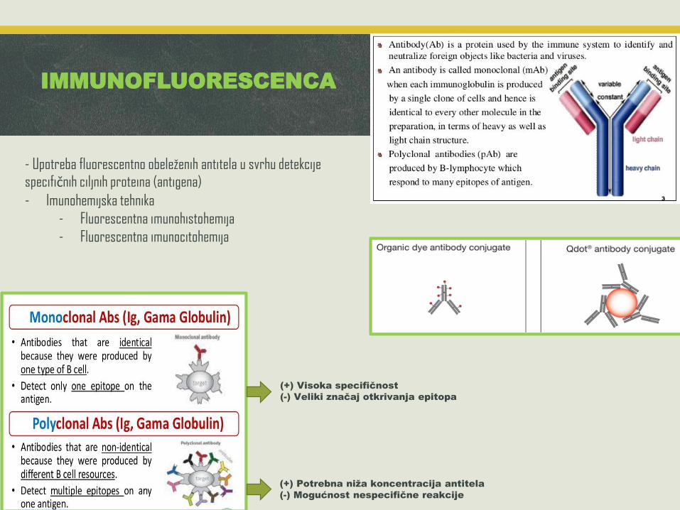
IMMUNOFLUORESCENCA
- Upotreba fluorescentno obeleženih antitela u svrhu detekcije specifičnih ciljnih proteina (antigena)
- Imunohemijska tehnika
- Fluorescentna imunohistohemija
- Fluorescentna imunocitohemija
(+) Potrebna niža koncentracija antitela
(-) Mogućnost nespecifične reakcije
(+) Visoka specifičnost
(-) Veliki značaj otkrivanja epitopa
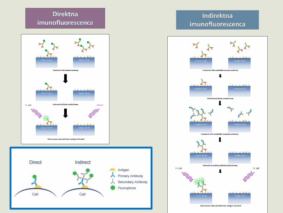
FLUORESCENTNA IMUNOHISTO/CITOHEMIJA(IMUNOFLUORESCENCA)

Opšti IF protokol
Priprema uzoraka: ĆELIJE: fiksacija/permeabilizacija
TKIVA: fiksacija/kalupljenje/sečenje
1. TKIVA: Deparafinizacija i rehidracija
2. Otkrivanje epitopa (antigen retrieval)
3. Ispiranje (PBS, TBS, PB)
4. Blokiranje nespecifičnog vezivanja antitela
5. Inkubacija - primarno anititelo
6. Ispiranje
7. Inkubacija – fluorescentno obeleženo sekundarno antitelo
8. Ispiranje
9. Montiranje (u antifading medijum – medijum koji umanjuje fotoizbeljivanje)
10. Mikroskopska analiza
Od ovog koraka u MRAKU!

FLUORESCENTNA IN SITU
HIBRIDIZACIJA
(FISH)
- Primena fluorescentno obeležene DNK/RNK sekvence u cilju identifikovanja položaja DNK/RNK sekvence in situ
- DNK FISH proba- RNK FISH proba
• Mapiranje gena – identifikacija položaja gena • Karyotyping – dijagnostika hromozomskih
aberacija• Spektralni karyotyping – mFISH• Analiza interfaznih hromozoma• Komparativna genomska hibridizacija
DNK FISH probe
RNK FISH proba
• Determinacija tipa ćelije• Determinacija stadijuma u diferencijaciji ćelije• Detekcija abnormalne/izmenjene ekspresije iRNA• Tkivna lokalizacija ekspresije određene iRNA
expression

Combination of different fluorescent techniques

We just scratched the surface…
REFERENCES
http://www.microscopyu.com http://www.olympusmicro.com http://micro.magnet.fsu.edu
Pawley J, Ed. “Handbook of Biological Confocal Microscopy”, 3rd ed. White J, Paddock SW, Eds. “Confocal Microscopy Methods and Protocols”, 2nd
ed. Robert L, Price W, Gray (Jay) J, “Basic Confocal Microscopy”
The Molecular Probes® Handbook—A Guide to Fluorescent Probes and Labeling Technologies: https://www.lifetechnologies.com/rs/en/home/references/molecular-probes-the-handbook.html
Fluorescence SpectraViewer: https://www.lifetechnologies.com/rs/en/home/life-science/cell-analysis/labeling-chemistry/fluorescence-spectraviewer.html

“Prilikom mikroskopiranja, zaboravite očekivanja, ne gajite predubeđenja, jer u suprotnom lako ćete napraviti grešku i videti ono što želite da vidite“.
“Ne zaboravite da tragate za istinom, i ukoliko napravite grešku, ne dozvolite da vas sujeta zavede da u njoj i istrajete.“
Henry Baker, The Microscope Made Easy, 1742.