Embed Size (px)
Citation preview

FLUIDS AND LUBRICANTS
Introduction
Used fluids such as engine oil, transmission fluid, antifreeze and brake fluid are hazardous wastes and must be disposed of properly. Before draining any fluid, consult your local authorities; in many areas, waste oil, etc. is being accepted as a part of recycling programs. A number of service stations and auto parts stores are also accepting waste fluids for recycling.
Be sure of the recycling center's policies before draining any fluids, as many will not accept different fluids that have been mixed together, such as oil and antifreeze.
Fuel and Engine Oil Recommendations
FUEL RECOMMENDATIONS
Some fuel additives contain chemicals that can damage the catalytic converter and/or oxygen sensor. Read all of the labels carefully before using any additive in the engine or fuel system.
All vehicles covered by this manual are designed to run on unleaded fuel. The used of a leaded fuel in a car requiring unleaded fuel will plug the catalytic converter and render it inoperative. It will also increase exhaust backpressure to the point where engine output will be severely reduced. The minimum octane rating of the unleaded fuel being used must be at least 87, which usually means regular unleaded, but some high performance engines may require higher ratings. Fuel should be selected for the brand and octane which performs best with your engine. Judge a gasoline by its ability to prevent pinging, its engine starting capabilities (cold and hot) and general all-weather performance.
For information regarding vehicles equipped with the Flexible Fuel (FF) system, refer to your owner's manual for fuel recommendations.
As far as the octane rating is concerned, refer to the General Engine Specifications Chart in Section 3 of this manual to find your engine and its compression ratio. If the compression ration is 9.0:1 or lower, in most cases a regular unleaded grade of gasoline can be used. If the compression ratio is 9.0:1-9.3:1, use a premium grade of unleaded fuel.
The use of a fuel too low in octane (a measurement of antiknock quality) will result in spark knock. Since many factors such as altitude, terrain, air temperature and humidity affect operating efficiency, knocking may result even though the recommended fuel is being used. If persistent knocking occurs, it may be necessary to switch to a higher grade of fuel. Continuous or heavy knocking may result in engine damage.
Your engine's fuel requirement can change with time, mainly due to carbon buildup, which will in turn change the compression ratio. If your
Стр. 1 из 34FLUIDS AND LUBRICANTS
18.11.2005http://www.chiltondiy.com/content/8687/8687_1_7.html

engine pings, knocks, or diesels (runs with the ignition off) switch to a higher grade of fuel. Sometimes just changing brands will cure the problem. If it becomes necessary to retard the timing from the specifications, don't change it more than a few degrees.
Retarded timing will reduce power output and fuel mileage, in addition to making the engine run hotter.
OIL RECOMMENDATIONS
The SAE (Society of Automotive Engineers) grade number indicates the viscosity of the engine oil and, thus, its ability to lubricate at a given temperature. The lower the SAE grade number, the lighter the oil; the lower the viscosity, the easier it is to crank the engine in cold weather. Oil viscosities should be chosen from those oils recommended for the lowest anticipated temperatures during the oil change interval. With the proper viscosity you will be assured of easy cold starting and sufficient engine protection.
Multi-viscosity oils (5W-30, 10W-30, etc.) offer the important advantage of being adaptable to temperature extremes. They allow easy starting at low temperatures, yet they give good protection at high speeds and engine temperatures. This is a decided advantage in changeable climates or in long distance driving.
The API (American Petroleum Institute) designation indicates the classification of engine oil used under certain given operating conditions. Only oils designated for use Service SG, or the latest superceding oil grade, should be used. Oils of the SG type perform a variety of functions inside the engine in addition to their basic function as a lubricant. Through a balanced system of metallic detergents and polymeric dispersants, the oil prevents the formation of high and low temperature deposits and also keeps sludge and dirt particles in suspension. Acids, particularly sulfuric acid, as well as other byproducts of combustion, are neutralized. Both the SAE grade number and the API designation can be found of the side of the oil bottle. Oil meeting API classification SG, SG/CC or SG/CD is recommended for use in your vehicle. Ford has filled your crankcase with SAE 5W-30 and recommends that you continue to use this as long as the outside temperatures don't exceed 100°F (38°C). There are other options, however, such as SAE 10W-30; refer to the accompanying oil viscosity/ambient temperature chart.
Click to enlarge
Engine oil viscosity recommendations
Стр. 2 из 34FLUIDS AND LUBRICANTS
18.11.2005http://www.chiltondiy.com/content/8687/8687_1_7.html

Synthetic Oil
There are excellent synthetic and fuel-efficient oils available that, under the right circumstances, can help provide better fuel mileage and better engine protection. However, these advantages come at a price, which can be three or four times the price per quart of conventional motor oils.
Before pouring any synthetic oils into your car's engine, you should consider the condition of the engine and the type of driving you do. It is also wise to check the vehicle manufacturer's position on synthetic oils.
Generally, it is best to avoid the use of synthetic oil in both brand new and older, high mileage engines. New engines require a proper break-in, and the synthetics are so slippery that they can impede this; most manufacturers recommend that you wait at least 5,000 miles (8,000 km) before switching to a synthetic oil. Conversely, older engines are looser and tend to use more oil; synthetics will slip past worn parts more readily than regular oil, and will be used up faster. If your car already leaks and/or uses oil (due to worn parts or bad seals/gaskets), it may leak and use more with a synthetic inside.
Consider your type of driving. If most of your accumulated mileage is on the highway at higher, steadier speed, a synthetic oil will reduce friction and probably help deliver better fuel mileage. If you choose to use synthetic oil in this case, synthetic oils which are certified and have the preferred viscosity may be used in your engine; however, the oil and filter must still be changed according to the maintenance schedule. Cars used under harder, stop-and-go, short hop circumstances should always be serviced more frequently, and for these cars, synthetic oil may not be a wise investment.
Engine
OIL LEVEL CHECK
Every time you stop for fuel, check the engine oil, making sure the engine has fully warmed and the vehicle is parked on a level surface. Because it takes a few minutes for all the oil to drain back to the oil pan, you should wait a few minutes before checking your oil. If you are doing this at a fuel stop, first fill the fuel tank, then open the hood and check the oil, (but don't get so carried away as to forget to pay for the fuel. Most station attendants won't believe that you forgot.)
1. Be sure your car is parked on level ground.
2. Shut off the engine. When checking the oil level, it is best for the engine to be at normal operating temperature, although checking the oil immediately after stopping will lead to a false reading. Wait a few minutes after turning off the engine to allow the oil to drain back into the crankcase.
3. Open the hood and locate the dipstick in a guide tube at the left-center, front of the engine. Pull the dipstick from its tube, wipe it clean with a lint-free rag, then reinsert it. Push it down firmly to assure that it is firmly seated in the tube.
Стр. 3 из 34FLUIDS AND LUBRICANTS
18.11.2005http://www.chiltondiy.com/content/8687/8687_1_7.html

4. Pull the dipstick out again and, holding it horizontally, read the oil level. The oil should be between the MAX and ADD marks on the dipstick. If the oil is below the ADD mark, add oil of the proper viscosity through the capped opening in the top of the cylinder head cover or filler tube, as applicable.
5. Reinsert the dipstick and check the oil level again after adding any oil. Approximately one quart of oil will raise the level from the ADD mark to the MAX mark. Be sure not to overfill the crankcase and waste the oil. Excess oil will generally be consumed at an accelerated rate.
OIL AND FILTER CHANGE
Change the engine oil and oil filter every 6 months or 5,000 miles (8,000 km). If the car is used in severe service or dusty conditions, change the engine oil and oil filter every 3 months or 3,000 miles (4,800 km). Following these recommended
Remove the dipstick from the engine
Wipe the dipstick with a clean, lint-free rag
Стр. 4 из 34FLUIDS AND LUBRICANTS
18.11.2005http://www.chiltondiy.com/content/8687/8687_1_7.html

intervals will help keep you car engine in good condition. Dirty oil loses its lubricating qualities and can cause premature wear in your engine.
1. Make sure the engine is at normal operating temperature (this promotes complete draining of the old oil).
2. Apply the parking brake and block the wheels, or raise and safely support the car evenly on jackstands.
3. Place a drain pan of about 6 quart capacity under the engine oil pan drain plug. Wipe the drain plug and surrounding area clean using an old rag.
4. Loosen the drain plug using the proper size box or socket wrench. Turn the plug out by hand, using a rag to shield your fingers from the hot oil. By keeping an inward pressure on the plug as you unscrew it, oil won't escape past the threads and you can remove it without being burned by the hot oil.
5. Quickly withdraw the plug and move your hands out of the way, but be careful not to drop the plug into the drain pan, as fishing it out can be an unpleasant mess. Allow all the old oil to drain completely into the pan, then inspect the drain plug gasket and replace it if necessary.
6. Install and carefully tighten the drain plug. Be careful not to overtighten the drain plug, otherwise you'll be buying a new pan or a trick replacement plug for stripped threads.
CAUTIONThe EPA warns that prolonged contact with used engine oil may cause a number of skin disorders, including cancer! You should make every effort to minimize your exposure to used engine oil. Protective gloves should be worn when changing the oil. Wash your hands and any other exposed skin areas as soon as possible after exposure to used engine oil. Soap and water, or waterless hand cleaner should be used.
Loosen and remove the oil drain plug
Стр. 5 из 34FLUIDS AND LUBRICANTS
18.11.2005http://www.chiltondiy.com/content/8687/8687_1_7.html

7. Move the drain pan under the engine oil filter. Use a strap-type or cap-type filter wrench to loosen the oil filter. Cover your hand with a rag and spin the filter off by hand; turn it slowly. Keep in mind that it's holding about one quart of dirty, hot oil.
8. Empty the oil filter into the drain pan and properly dispose of the filter.
9. Wipe the engine filter mount clean with a lint-free rag. Coat the rubber gasket on the new oil filter with clean engine oil, applying it with a finger. Carefully start the filter onto the threaded engine mount, by hand. When the filter touches the adapter surface, give it another 1/2-1 turn (no more, or you'll squash the gasket and it will leak).
10. Lower the vehicle to the ground. Refill the crankcase to specification with the proper grade and type motor oil. Install the filler cap and start the engine. Allow the engine to idle and check for oil leaks. Shut off the engine, wait several minutes,
Having the engine at normal operating temperature will promote complete draining of the engine oil
Remove the oil filter using a strap-type filter wrench
Стр. 6 из 34FLUIDS AND LUBRICANTS
18.11.2005http://www.chiltondiy.com/content/8687/8687_1_7.html

then check the oil level with the dipstick. The oil level will drop as the filter fills up with oil. Add oil to the proper dipstick level.
When you have finished this job, you will notice that you now possess four or five quarts of dirty oil. Pour it into plastic jugs, such as clean milk or antifreeze containers. Then, locate a service station or automotive parts store where you can pour it into their used oil tank for recycling.
Remove the oil filler cap located on the valve cover
Refill the crankcase with the proper grade and capacity of engine oil
WARNINGPouring used motor oil into a storm drain not only pollutes the environment, it violates Federal law. Dispose of waste oil properly.
Стр. 7 из 34FLUIDS AND LUBRICANTS
18.11.2005http://www.chiltondiy.com/content/8687/8687_1_7.html
Manual Transaxle
FLUID RECOMMENDATIONS AND LEVEL CHECK
Each time the engine oil is changed, the fluid level of the transaxle should be checked. The car must be resting on level ground or supported on jackstands (front and back) evenly. To check the fluid, remove the filler plug, located on the
upper front (driver's side) of the transaxle with a 3/8 in. (10mm) extension and ratchet.
The filler plug has a hex head; do not mistake any other bolts for the filler plug. Do not overfill the transaxle. The oil level should be even with the edge of the
filler hole or within 1/4 in. (6mm) of the hole. If the oil is low, add Motorcraft Type F or Dexron®II automatic transmission fluid.
Automatic Transaxle
FLUID RECOMMENDATIONS AND LEVEL CHECK
A dipstick is provided in the engine compartment to check the level of the automatic transaxle. Check the Maintenance Component Location charts at the end of this section for the dipstick location on your vehicle. Be sure the car is on level ground and that the car's engine and transaxle have reached normal operating temperatures.
1. Start the engine, set the parking brake, and put the transaxle selector lever in the PARK position.
2. Move the selector lever through all the positions and return to the PARK position. DO NOT TURN OFF THE ENGINE DURING THE FLUID LEVEL CHECK.
3. Clean all dirt from the dipstick cap before removing the dipstick. Remove the dipstick and wipe clean.
4. Reinsert the dipstick making sure it is fully seated. Pull the dipstick out of the tube
Checking the manual transaxle fluid-early model 2.5L shown
Стр. 8 из 34FLUIDS AND LUBRICANTS
18.11.2005http://www.chiltondiy.com/content/8687/8687_1_7.html

and check the fluid level. The fluid level should be between the FULL and ADD marks.
5. If necessary, add enough fluid through the dipstick tube/filler to bring the level to the FULL mark on the dipstick. Use Dexron®II or Mercon® fluid in the ATX 3-speed transaxle, AXOD and AXOD-E overdrive transaxles.
Do NOT overfill the transaxle. Doing so can cause damage to the transaxle. Make sure the dipstick is fully seated. If by chance you overfill the transaxle, thread a small piece of rubber vacuum hose into the dipstick tube until it hits the bottom, then withdraw the excess fluid using a large, clean turkey baster or equivalent.
DRAIN AND REFILL
In normal service it should not be necessary or required to drain and refill the automatic transaxle. However, under severe operation or dusty conditions, the fluid should be changed every 20 months or 20,000 miles (32,000 km).
1. Raise the car and safely support it on jackstands. If the pan is equipped with a drain plug, drain the fluid into a suitable container.
2. If the pan does not have a drain plug, place a suitable drain pan underneath the transaxle oil pan. Loosen the oil pan mounting bolts and allow the fluid to drain until it reaches the level of the pan flange. Remove the attaching bolts, leaving one end attached so that the pan will tip and the rest of the fluid will drain.
3. Remove the oil pan and thoroughly clean it. Remove the old gasket. Make sure that the gasket mounting surfaces are clean.
4. Unfasten the transaxle filter screen retaining bolt and remove the screen.
5. Install a new filter screen and O-ring. Place a new gasket on the pan and install the pan to the transaxle. Torque the transaxle pan to 15-19 ft. lbs. (20-26 Nm).
6. Fill the transaxle to the correct level. Remove the jackstands and lower the car to the ground.
Cooling System
On vehicles equipped with a coolant recovery reservoir, removal of theradiator cap is normally not required, except for when draining the system orinspecting the radiator and cap.
Servicing the cooling system can be a dangerous matter unless the proper precautions are observed. It is best to check the coolant level in the radiator
CAUTIONNEVER remove the radiator cap under any conditions while the engine is hot! Failure to follow these instructions could result in damage to the coolingsystem and engine, as well as personal injury. To avoid having scalding hotcoolant or steam blow out of the radiator, use extreme care whenever you areremoving the radiator cap. Wait until the engine has cooled, then wrap a thickcloth around the radiator cap and turn it slowly to the first stop. Step backwhile the pressure is released from the cooling system. When you are sure thepressure has been released, press down on the radiator cap (still holding the cloth in position), then turn and remove the radiator cap.
Стр. 9 из 34FLUIDS AND LUBRICANTS
18.11.2005http://www.chiltondiy.com/content/8687/8687_1_7.html

when the engine is cold. All vehicles covered by this manual should be equipped with a coolant recovery reservoir. If the coolant level is at or near the FULL COLD line (engine cold) or the FULL HOT line (engine hot), the level is satisfactory. Always be certain that the filler caps on both the radiator and the recovery reservoir are closed tightly.
If the coolant level is found to be low, add a 50/50 mixture of coolant that meets Ford specifications, such as Ford Cooling System Fluid, Prestone® II or other approved coolant and clean water. Coolant may be added either through the filler neck on the radiator or directly into the recovery reservoir.
It is wise to pressure check the cooling system at least once a year. If the coolant level is chronically low or rusty, the system should be thoroughly checked for leaks.
At least once every two years or 30,000 miles (48,000 km), the engine and radiator should be inspected, flushed and refilled with fresh coolant. If the coolant is left in the system too long, it loses its ability to prevent rust corrosion. If the coolant has too much water, it won't protect against freezing.
The pressure cap should be examined for signs of age or deterioration. The fan belt and other drive belts should be inspected and adjusted to the proper tension.
Hose clamps should be tightened, and soft or cracked hoses replaced. Damp spots, or accumulations of rust or dye near the hoses, water pump or other areas indicate possible leakage, which must be corrected before filling the system with fresh coolant.
FLUID RECOMMENDATIONS
This engine has an aluminum cylinder head and requires a corrosion inhibiting coolant formulation to avoid radiator damage. Use only a permanent type coolant that meets Ford Specifications such as Ford Cooling System Fluid, Prestone® II, or other approved coolants. Mix the coolant with clean water until a 50/50 solution is attained.
LEVEL CHECK
The cooling system of your car contains, among other items, a radiator and an expansion tank/recovery reservoir. When the engine is running heat is generated. The rise in temperature causes the coolant, in the radiator, to expand and builds up internal pressure. When a certain pressure is reached, a pressure relief valve in the radiator filler cap (pressure cap) is lifted from its seat and allows coolant to flow through the radiator filler neck, down a hose, and into the expansion reservoir.
When the system temperature and pressure are reduced in the radiator, the water in the expansion reservoir is siphoned back into the radiator.
On systems with a coolant recovery tank, maintain the coolant level between the
CAUTIONNEVER add coolant to a hot engine unless it is running. If the engine is notrunning, you run the risk of cracking the engine block.
Стр. 10 из 34FLUIDS AND LUBRICANTS
18.11.2005http://www.chiltondiy.com/content/8687/8687_1_7.html

marks on the recovery reservoir.
If, for some reason, the vehicle does not have a coolant recovery tank,maintain the coolant level 1-2 in. (25-51mm) below the bottom of the radiatorfiller neck when the engine is cold and 1 in. (25mm) below the bottom of thefiller neck when the engine is hot.
DRAIN AND REFILL
For best protection against freezing and overheating, maintain an approximate 50% water and 50% ethylene glycol (or other suitable) antifreeze mixture in the cooling system. Do not mix different brands of antifreeze to avoid possible chemical damage to the cooling system.
Avoid using water that is known to have a high alkaline content or is very hard, except in emergency situations. Drain and flush the cooling system as soon as possible after using such water.
NEVER add cold water to an overheated engine while the engine is notrunning.
After filling the radiator, run the engine until it reaches normal operating temperature, to make sure that the thermostat has opened and all the air is bled from the system.
Draining Coolant
To drain the coolant, connect a hose approximately 18 in. (46cm) long, with an
inside diameter of 3/8 in. (9.5mm), to the nipple on the drain valve located on the
CAUTIONCover the radiator cap with a thick cloth before removing it from a radiatorin a vehicle that is hot. Turn the cap counterclockwise slowly until pressurecan be heard escaping. Allow all pressure to escape from the radiator beforecompletely removing the radiator cap. It is best to allow the engine to cool,if possible, before removing the radiator cap.
CAUTIONThe cooling fan motor is controlled by a temperature switch. The fan maycome on and run even when the engine is off and will continue to run until theengine has cooled to a predetermined level. Take care not to get your fingers,etc. close to the fan blades.
CAUTIONWhen draining the coolant, keep in mind that cats and dogs are attracted byethylene glycol antifreeze, and are quite likely to drink any that is left inan uncovered container or in puddles on the ground. This will prove fatal insufficient quantity. Always drain the coolant into a sealable container.Coolant should be reused unless it is contaminated or several years old.
Стр. 11 из 34FLUIDS AND LUBRICANTS
18.11.2005http://www.chiltondiy.com/content/8687/8687_1_7.html

bottom of the radiator. With the engine cool, set the heater control to the maximum heat position. Remove the radiator cap and open the drain valve or
loosen the Allen® head plug 3/16 in. (5mm), allowing the coolant to drain into a suitable container. When all of the coolant is drained, remove the hose and close the drain valve or Allen® head plug.
Replacing Coolant
If there is any evidence of rust or scaling in the cooling system, the system should be flushed thoroughly before refilling. Refer to the flushing/cleaning procedure, later in this section. With the engine OFF and COOL:
1. Using a funnel, add the designated quantity of a 50% coolant and 50% water solution to the radiator.
Open the drain valve located on the bottom of the radiator
Attaching a small hose to the draincock will help direct the flow of coolant into the drain pan, thereby reducing the mess
Стр. 12 из 34FLUIDS AND LUBRICANTS
18.11.2005http://www.chiltondiy.com/content/8687/8687_1_7.html

2. Reinstall the radiator cap to the fully installed position, then back it off to the first stop.
3. Start and idle the engine until the upper radiator hose is warm.
4. Immediately shut off the engine. Cautiously remove the radiator cap and add water until the radiator is full. Reinstall the radiator cap securely.
5. Add coolant to the ADD mark on the reservoir, then fill to the FULL HOT mark with water.
All vehicles covered by this manual should be equipped with a coolant reservoir
Add coolant to the correct marks on the reservoir
Стр. 13 из 34FLUIDS AND LUBRICANTS
18.11.2005http://www.chiltondiy.com/content/8687/8687_1_7.html

6. Check the system for leaks and return the heater temperature control to its normal position.
RADIATOR CAP INSPECTION
Allow the engine to cool sufficiently before attempting to remove the radiator cap. Use a rag to cover the cap, then remove by pressing down and turning counterclockwise to the first stop. If any hissing is noted (indicating the release of pressure), wait until the hissing stops completely, then press down again and turn counterclockwise until the cap can be removed.
Check the coolant level to make sure it is sufficient
Allow the engine to cool before attempting to remove the radiator cap. DO NOT remove the cap while the engine is hot!
CAUTION
Стр. 14 из 34FLUIDS AND LUBRICANTS
18.11.2005http://www.chiltondiy.com/content/8687/8687_1_7.html
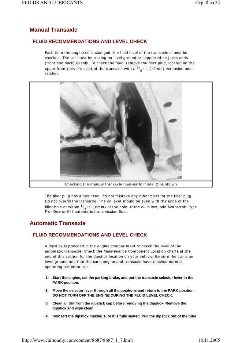
Check the condition of the radiator cap gasket and seal inside the cap. The radiator cap is designed to seal the cooling system under normal operating conditions which allow the buildup of a certain amount of pressure (this pressure rating is stamped or printed on the cap). The pressure in the system raises the boiling point of the coolant to help prevent overheating. If the radiator cap does not seal properly, the boiling point of the coolant is lowered and overheating will likely occur. If the cap must be replaced, purchase a new cap according to the pressure rating which is specified for your vehicle.
Prior to installing the radiator cap, inspect and clean the filler neck. If you are reusing the old cap, clean it thoroughly with clear water. After installing the cap, make sure the arrows align with the overflow hose.
FLUSHING AND CLEANING THE SYSTEM
1. Drain the cooling system, including the radiator and engine block. Close the drain valve/plugs, then refill the system with water at the radiator fill neck.
2. Allow the engine to idle for about 5 minutes. Turn the engine off. Drain the cooling system again.
3. Repeat the above steps until nearly clear water is drained from the radiator. Allow the remaining water to drain and then close the draincock.
4. Disconnect the overflow hose from the radiator filler neck. Remove the coolant recovery reservoir from the fender apron and empty the fluid.
5. Flush the reservoir with clean water. Reinstall the reservoir.
6. Fill the radiator and cooling system with the proper concentration of coolant and water. Don't forget to also fill the reservoir to its proper level.
Brake Master Cylinder
FLUID RECOMMENDATIONS
When adding to or refilling the master cylinder, be sure to use Heavy Duty (H. D.)
DO NOT attempt to remove the radiator cap while the engine is hot. Severepersonal injury from steam burns can result.
Check the condition of the radiator cap gasket, and the seal inside of the cap
Стр. 15 из 34FLUIDS AND LUBRICANTS
18.11.2005http://www.chiltondiy.com/content/8687/8687_1_7.html

brake fluid that meets or exceeds Ford Motor Company specification ESA-M6C25-A, such as Motorcraft C6AZ-19542-AA or BA or equivalent.
Click to enlarge
Click to enlarge
LEVEL CHECK
It should be obvious how important the brake system is to the safe operation of your vehicle. Maintaining the correct level of clean brake fluid is critical for the
CAUTIONBrake fluid damages paint. It also absorbs moisture from the air; never leave a container or the master cylinder uncovered any longer than necessary. All parts in contact with the brake fluid (master cylinder, hoses, plunger assemblies, etc.) must be kept clean, since any contamination of the brake fluid can adversely affect braking performance.
Brake master cylinder components-sedan
Brake master cylinder components-station wagon
Стр. 16 из 34FLUIDS AND LUBRICANTS
18.11.2005http://www.chiltondiy.com/content/8687/8687_1_7.html

proper operation of your vehicle. A low fluid level indicates a need for service (there may be a leak in the system or the brake pads may just be worn and in need of replacement). In any case, the brake fluid level should be inspected at least during every oil change, but more often is desirable. Every time you open the hood is a good time to glance at the master cylinder reservoir.
The brake master cylinder is located under the hood, on the left side (driver's side) of the firewall. Check the Maintenance Component Location charts, at the end of this section, for the exact location on your vehicle. Before removing the master cylinder reservoir cap, make sure the vehicle is resting on level ground and clean all the dirt away from the top of the master cylinder. Remove the master cylinder cap.
Before taking the cap off of the master cylinder, make sure all dirt and/or debris is cleaned off
When adding brake fluid to the master cylinder, use only clean, fresh fluid from a sealed container
Стр. 17 из 34FLUIDS AND LUBRICANTS
18.11.2005http://www.chiltondiy.com/content/8687/8687_1_7.html

Some vehicles covered by this manual are equipped with and Anti-lock Brake System (ABS). To check the fluid level in the master cylinder reservoir of a vehicle equipped with ABS:
1. Turn the ignition OFF.
2. Pump the brake pedal at least 20 times or until the pedal feel becomes hard, then turn the ignition key to the ON position.
3. Wait at least 60 seconds to be sure that the fluid level is stabilized.
4. The fluid level should be at the MAX line as indicated on the side of the reservoir.
The fluid level will lower somewhat due to normal brake lining wear. However, if the level is less than half the volume of the reservoir, check the brake system for leaks. Leaks in the brake hydraulic system most commonly occur at the rear wheel cylinders or at the front calipers. Leaks at the brake lines or the master cylinder can also be the cause of lost brake fluid. If a leak is detected, repair it and bleed the system, as described in Section 9 .
5. If the level is low, remove the cap and add Heavy Duty Brake Fluid (Dot 3) until the MAX line is reached. The level of the brake fluid should be at the MAX line embossed on the translucent plastic reservoir of the master cylinder.
If the master cylinder reservoir has a cap with an expanding rubber diaphragm, be sure to push the diaphragm up into the cap before installing the cap.
Power Steering Pump
FLUID RECOMMENDATIONS
Use Ford Motor Company's premium power steering fluid E6AZ-19582-AA (ESW-M2C33-F) or equivalent.
LEVEL CHECK
You should check the level of the power steering fluid at least twice a year. You may check the fluid when the engine is either hot or cold.
To check the fluid when the engine is hot:
1. Start the engine and let it run until it reaches normal operating temperature.
2. While the engine is idling, turn the steering wheel all the way to the right and then to the left several times. Turn the engine OFF.
3. Open the hood and remove the power steering pump dipstick located on the right side (passenger side) near the front of the engine.
4. Wipe the dipstick clean and reinsert it into the pump reservoir. Withdraw the dipstick and note the fluid level. The level must show in the FULL HOT range on the dipstick.
5. If the power steering fluid is low, add the proper fluid in small amounts, continuously checking the level, until you reach the FULL HOT range, but do not overfill. Remove any excess fluid with a clean suction bulb or equivalent.
Стр. 18 из 34FLUIDS AND LUBRICANTS
18.11.2005http://www.chiltondiy.com/content/8687/8687_1_7.html

Make sure the cap is clean before removing it; this will prevent dirt from contaminating the system
If checking the fluid when the engine is hot, it should be within the proper marks of the FULL HOT side of the dipstick
Стр. 19 из 34FLUIDS AND LUBRICANTS
18.11.2005http://www.chiltondiy.com/content/8687/8687_1_7.html

If you check the power steering fluid when the engine is cold, make sure that the fluid level reaches the FULL COLD range on the dipstick. However, the reading will only be accurate if the fluid temperature is approximately 50-85°F (10-30°C).
Steering Rack
FLUID RECOMMENDATIONS
Use Ford Motor Company's premium power steering fluid E6AZ-19582-AA (ESW-M2C33-F) or equivalent.
Windshield Washer Pump
Power steering dipstick fluid level marks for checking the fluid when the engine is cold
Add power steering fluid in small amounts, but do not overfill
Стр. 20 из 34FLUIDS AND LUBRICANTS
18.11.2005http://www.chiltondiy.com/content/8687/8687_1_7.html

FLUID RECOMMENDATIONS AND LEVEL CHECK
The windshield washer pump fluid reservoir is a plastic container usually found on the right (passenger) side of the engine compartment. If equipped, the rear window washer pump fluid reservoir is located under the rear right-hand quarter panel and the fill cap is found outside, near the liftgate opening. The reservoir should be filled to the top of the container using a washer fluid solution that can be found at most auto parts stores. Do NOT further dilute the solution (unless it is sold as a concentrate; if so, follow the manufacturer's instructions), as this will adversely affect its ability to keep from freezing at low temperatures. Also, never place another fluid, such as ethylene glycol antifreeze in the reservoir, as other fluids could damage pump seals.
Click to enlarge
Click to enlarge
Body Maintenance
Regular body maintenance preserves the vehicle's appearance during the life of the vehicle. When washing or waxing the exterior of the vehicle, be sure to use
Windshield washer reservoir location and components-late model sedan shown; early model similar
Windshield washer reservoir location and components-station wagon shown
Стр. 21 из 34FLUIDS AND LUBRICANTS
18.11.2005http://www.chiltondiy.com/content/8687/8687_1_7.html

products that meet or exceed Ford Motor Company's specifications. Replace all damaged weatherstrips as needed. Replace all chipped or cracked glass as needed. Drain holes are located under each rocker panel, quarter panel and door; these holes should be kept open to allow water to drain.
Rear Wheel Bearings
These procedures are for rear wheel bearings only. For informationregarding front wheel bearings, please refer to Section7 of this manual.
Once every 30,000 miles (48,000 km), clean and repack the rear wheel bearings using Long-Life Lubricant, Ford part no. C1AZ-19590-B, or equivalent.
Click to enlarge
Sodium-based grease is not compatible with lithium-based grease. Read thepackage labels and be careful not to mix the two types. If there is any doubt asto the type of grease used, completely clean the old grease from the bearingand hub before repacking.
Before handling the bearings, there are a few things that you should remember to do and not to do.
Remember to DO the following:
Remove all outside dirt from the housing before exposing the bearing.
Treat a used bearing as gently as you would a new one.
Work with clean tools in clean surroundings.
Use clean, dry canvas gloves, or at least clean, dry hands.
Use clean solvents and flushing fluids.
Use clean paper when laying out the bearings to dry.
CAUTIONWhen servicing the rear wheel bearings, use caution because brake shoes maycontain asbestos, which has been determined to be a cancer causing agent. NEVERclean the brake surfaces with compressed air! Avoid inhaling any dust from anybrake surface! When cleaning brake surfaces, use a commercially available brakecleaning fluid.
Exploded view of rear wheel assembly-1989 vehicle shown
Стр. 22 из 34FLUIDS AND LUBRICANTS
18.11.2005http://www.chiltondiy.com/content/8687/8687_1_7.html

Protect disassembled bearings from rust and dirt by covering them up.
Use clean rags to wipe bearings.
Keep the bearings in oil-proof paper when they are to be stored or are not in use.
Clean the inside of the housing before replacing the bearing.
Also observe the following:
Do NOT work in dirty surroundings.
Do NOT use dirty, chipped or damaged tools.
Do NOT work on wooden work benches or use wooden mallets.
Do NOT handle bearings with dirty or moist hands.
Do NOT use gasoline for cleaning; use a safe solvent.
Do NOT spin-dry bearings with compressed air as they will be damaged.
Do NOT spin dirty bearings.
Do NOT use cotton waste or dirty cloths to wipe bearings.
Do NOT scratch or nick bearing surfaces.
Do NOT allow the bearing to come in contact with dirt or rust at any time.
ADJUSTMENT
The following procedure applies only to 1986-89 vehicles. Adjustment is not possible on 1990-95 vehicles. This procedure should be performed whenever the wheel is excessively loose on the spindle or it does not rotate freely.
The rear wheel uses a tapered roller bearing which may feel loose whenproperly adjusted; this condition should be considered normal.
1. Remove the wheel cover or ornament/nut cover. Loosen the lug nuts if the wheel must be removed.
If the vehicle is equipped with styled steel or aluminumwheels, the wheel/tire assembly must be removed to access the dust cover forremoval.
2. Raise and safely support the rear of the vehicle until the tires clear the floor.
3. If necessary, remove the wheel.
4. Remove the hub grease cap, taking care not to damage it.
5. Remove the cotter pin and the nut retainer. Discard the cotter pin.
6. Back off the hub nut one full turn.
Стр. 23 из 34FLUIDS AND LUBRICANTS
18.11.2005http://www.chiltondiy.com/content/8687/8687_1_7.html
Click to enlarge
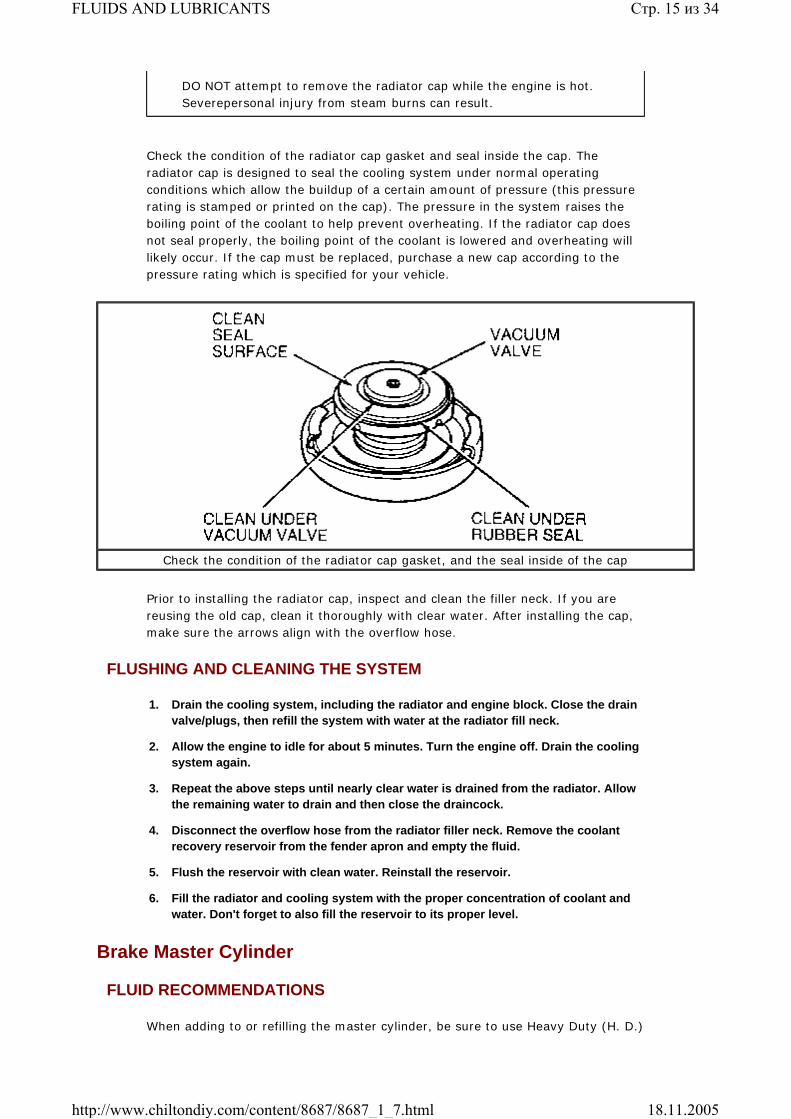
7. Tighten the adjusting nut to 17-25 ft. lbs. (23-24 Nm) while rotating the hub and drum assembly to seat the bearings. Back off the adjusting nut 1/2 turn, then retighten it to 24-28 inch lbs. (2.7-3.2 Nm).
8. Position the nut retainer over the adjusting nut so the slots are in line with the cotter pin hole, without rotating the adjusting nut.
9. Install a new cotter pin and bend the ends around the retainer flange.
10. Check the hub rotation. If the hub rotates freely, install the grease cap. If not, check the bearings for damage and replace, as necessary.
11. If applicable, install the wheel and tire assembly, as well as the wheel cover/ornament, then lower the vehicle.
REMOVAL, PACKING & INSTALLATION
With Drum Brakes
1986-89 VEHICLES
1. Raise the vehicle and support it safely on jackstands. Remove the wheel from the
Wheel bearing adjustment-1986-89 vehicles ONLY
Стр. 24 из 34FLUIDS AND LUBRICANTS
18.11.2005http://www.chiltondiy.com/content/8687/8687_1_7.html

hub and drum.
2. Remove the grease cap from the hub. Remove the cotter pin, nut retainer, adjusting nut and keyed flat washer from the spindle. Discard the cotter pin.
Pry the grease cap from the hub. Be careful not to distort or damage the flange
After removing the grease cap, unbend the cotter pin
Стр. 25 из 34FLUIDS AND LUBRICANTS
18.11.2005http://www.chiltondiy.com/content/8687/8687_1_7.html

Grasp the cotter pin with needle-nose pliers and pull or pry it free of the spindle. Discard the cotter pin and replace it with a new one during installation
Remove the adjusting nut from the spindle
Стр. 26 из 34FLUIDS AND LUBRICANTS
18.11.2005http://www.chiltondiy.com/content/8687/8687_1_7.html

3. Pull the hub and drum assembly off the spindle, being careful not to drop the outer bearing assembly.
4. Remove the outer bearing assembly.
Remove the keyed washer from the spindle
Remove the outer bearing assembly. Note that this can be done with the hub and drum on or off the vehicle
Стр. 27 из 34FLUIDS AND LUBRICANTS
18.11.2005http://www.chiltondiy.com/content/8687/8687_1_7.html

5. Using seal remover tool 1175-AC or equivalent, remove and discard the grease seal. Remove the inner bearing assembly from the hub.
Remove the hub and drum assembly from the spindle
Removing the grease seal; discard the seal after removing. Note that the preferred method for removing the seal is with a proper seal remover tool
Стр. 28 из 34FLUIDS AND LUBRICANTS
18.11.2005http://www.chiltondiy.com/content/8687/8687_1_7.html

6. Wipe all the lubricant from the spindle and inside of the hub. Cover the spindle with a clean cloth, then vacuum all loose dust and dirt from the brake assembly. Carefully remove the cloth to prevent dirt from falling on the spindle.
7. Clean both bearing assemblies and cups using a suitable solvent. Inspect the bearing assemblies and cups for excessive wear, scratches, pits or other damage and replace as necessary.
8. If the cups are to be replaced, remove them with impact slide hammer T50T-100-A and bearing cup puller T77F-1102-A, or equivalent.
To install:
9. If the inner and outer bearing cups were removed, install the replacement cups using driver handle T80T-4000-W as well as bearing cup replacers T73T-1217-A and T77F-1217-A, or equivalent. Support the drum hub on a block of wood to prevent damage. Make sure the cups are properly seated in the hub.
Do NOT use the cone and roller assembly to installthe cups. This will result in damage to the bearing cup as well as the cone androller assembly.
10. Make sure all of the spindle and bearing surfaces are clean.
11. Using a bearing packer, pack the bearing assemblies with a suitable wheel bearing grease. If a packer is not available, work in as much grease as possible between the rollers and cages with your hands; also grease the cup surfaces.
Allow all of the cleaning solvent to dry before repackingthe bearings. Do not spin-dry the bearings with air pressure.
12. Install the inner bearing cone and roller assembly in the inner cup. Apply a light film of grease to the lips of a new grease seal and install the seal with rear hub seal replacer T56T-4676-B or equivalent. Make sure the retainer flange is seated all around.
With the seal removed, the inner bearing may be removed from the hub
Стр. 29 из 34FLUIDS AND LUBRICANTS
18.11.2005http://www.chiltondiy.com/content/8687/8687_1_7.html

13. Apply a light film of grease on the spindle shaft bearing surfaces. Install the hub and drum assembly on the spindle. Keep the hub centered on the spindle to prevent damage to the grease seal and spindle threads.
14. Install the outer bearing assembly and the keyed flat washer on the spindle.
15. Install the adjusting nut and adjust the wheel bearings, as previously described.
16. Install a new cotter pin, then install the grease cap.
Replace the grease cap if there is corrosion on the innersurface of the cap.
17. Place the wheel and tire on the drum, then install the lug nuts and tighten them alternately to draw the wheel evenly against the hub and drum.
18. Carefully lower the vehicle, then tighten the lug nuts (with a hand tool) to 85-105 ft. lbs. (115-142 Nm). Do NOT use power tools to tighten the lug nuts. Install the wheelcover.
1990-95 VEHICLES
1. Loosen the rear wheel lug nuts.
2. Raise and safely support the vehicle on jackstands.
3. Remove the rear wheel and tire assembly.
4. Remove the two pushnuts retaining the brake drum to the hub, then remove the drum.
5. Remove and discard the hub cap grease seal from the rear hub assembly.
6. Remove the rear axle hub retaining nut, then discard the nut.
7. Remove the bearing and hub assembly from the rear wheel spindle.
This is NOT the proper method for installing the grease seal, refer to the procedure for the proper tool to use when installing the seal
Стр. 30 из 34FLUIDS AND LUBRICANTS
18.11.2005http://www.chiltondiy.com/content/8687/8687_1_7.html

Click to enlarge
To install:
8. Position the bearing and hub assembly onto the spindle.
9. Install a new rear axle wheel hub retaining nut, then tighten the nut to 188-254 ft. lbs. (255-345 Nm).
10. Using Coil Remover T89P-19623 or equivalent, install a new hub cap grease seal. Lightly tap on the tool until the seal is fully seated.
11. Install the brake drum onto the rear hub, then attach the two pushnuts that retain the brake drum.
12. Install the wheel and tire assembly, then carefully lower the vehicle.
With Disc Brakes
1989 SHO
1. Raise the vehicle and support it safely on jackstands. Remove the tire and wheel assembly from the hub.
2. Remove the brake caliper after removing the 2 bolts that attach the caliper support to the cast iron brake adapter. Do NOT remove the caliper pins from the caliper assembly. Lift the caliper off of the rotor and support it with a length of wire. Do not allow the caliper assembly to hang from the brake hose.
3. Remove the rotor from the hub by pulling it off the hub bolts. If the rotor is difficult to remove, strike the rotor sharply between the studs with a rubber or plastic hammer.
4. Remove the grease cap from the hub. Remove the cotter pin, nut retainer, adjusting nut and keyed flat washer from the spindle. Discard the cotter pin.
5. Pull the hub assembly off of the spindle. Remove the outer bearing assembly.
6. Using seal remover tool 1175AC or equivalent, remove and discard the grease seal. Remove the inner bearing assembly from the hub.
7. Wipe all of the lubricant from the spindle and inside of the hub. Cover the spindle with a clean cloth and vacuum all of the loose dust and dirt from the brake assembly. Carefully remove the cloth to prevent dirt from falling on the spindle.
Exploded view of the rear wheel assembly-1990-95 vehicles with drum brakes
Стр. 31 из 34FLUIDS AND LUBRICANTS
18.11.2005http://www.chiltondiy.com/content/8687/8687_1_7.html

8. Clean both bearing assemblies and cups using a suitable solvent. Inspect the bearing assemblies and cups for excessive wear, scratches, pits or other damage and replace as necessary.
9. If the cups are being replaced, remove them with impact slide hammer tool T50T-100-A and bearing cup puller tool T77F-1102-A, or equivalent.
Click to enlarge
To install:
10. If the inner and outer bearing cups were removed, install the replacement cups using driver handle tool T80T-4000-W as well as bearing cup replacer tools T73F-1217-A and T77F-1217-B, or equivalent. Support the hub on a block of wood to prevent damage. Make sure the cups are properly seated in the hub.
Do not use the cone and roller assembly to install the cups.This will result in damage to the bearing cup, as well as the cone and rollerassembly.
11. Make sure all of the spindle and bearing surfaces are clean.
12. Pack the bearing assemblies with suitable wheel bearing grease using a bearing packer. If a packer is not available, work in as much grease as possible between the rollers and the cages with your hands. Grease the cup surfaces.
Allow all of the cleaning solvent to dry before repackingthe bearings. Do not spin-dry the bearings with compressed air.
13. Place the inner bearing cone and roller assembly in the inner cup. Apply a light film of grease to the lips of a new grease seal and install the seal with rear hub seal replacer tool T56T-4676-B or equivalent. Make sure the retainer flange is seated all around.
14. Apply a light film of grease on the spindle shaft bearing surfaces. Install the hub assembly on the spindle. Keep the hub centered on the spindle to prevent damage to the grease seal and spindle threads.
Rear wheel assembly-1989 SHO
Стр. 32 из 34FLUIDS AND LUBRICANTS
18.11.2005http://www.chiltondiy.com/content/8687/8687_1_7.html

15. Install the outer bearing assembly and keyed flat washer on the spindle. Install the adjusting nut and adjust the wheel bearings as previously described. Install a new cotter pin and the grease cap.
16. Install the disc brake rotor to the hub assembly. Install the disc brake caliper over the rotor.
17. Install the wheel and tire assembly, then lower the vehicle.
1990-95 VEHICLES
1. Raise and safely support the vehicle with jackstands.
2. Remove the rear wheel and tire assembly.
3. Remove the rear caliper assembly from the brake adapter. Support the caliper assembly with a length of wire.
4. Remove the push-on nuts that retain the rotor to the hub, then remove the rotor.
5. Remove and discard the hub cap grease seal from the bearing and hub assembly.
6. Remove and discard the rear axle bearing and hub assembly retainer.
7. Remove the rear wheel hub from the rear wheel spindle.
To install:
Click to enlarge
Exploded view of the rear wheel assembly-sedan shown
Стр. 33 из 34FLUIDS AND LUBRICANTS
18.11.2005http://www.chiltondiy.com/content/8687/8687_1_7.html

Click to enlarge
8. Position the rear hub on the rear wheel spindle.
9. Install a new rear axle wheel hub retainer. Tighten the retainer to 188-254 ft. lbs. (255-345 Nm).
10. Using Coil Remover T89P-19623-FH or equivalent, install a new rear hub cap grease seal. Gently tap on the tool until the rear hub cap grease seal is fully seated.
11. Install the rear disc brake rotor on the hub. Install the two push-on nuts that retain the rotor.
12. Install the rear disc brake caliper to the brake adapter.
13. Install the wheel and tire assembly, then carefully lower the vehicle.
Chilton® Automotive Information Systems. © 2004 Thomson Delmar Learning.
Exploded view of the rear wheel assembly-station wagon shown
Стр. 34 из 34FLUIDS AND LUBRICANTS
18.11.2005http://www.chiltondiy.com/content/8687/8687_1_7.html


![L-14 Fluids [3] Fluids at rest Fluid Statics Fluids at rest Fluid Statics Why things float Archimedes’ Principle Fluids in Motion Fluid Dynamics](https://img.pdfslide.us/doc/110x75/56649ced5503460f949ba1d5/l-14-fluids-3-fluids-at-rest-fluid-statics-fluids-at-rest-fluid-statics.jpg)


![L-14 Fluids [3] Fluids at rest Fluids at rest Why things float Archimedes’ Principle Fluids in Motion Fluid Dynamics Fluids in Motion Fluid Dynamics](https://img.pdfslide.us/doc/110x75/56649d845503460f94a6ab30/l-14-fluids-3-fluids-at-rest-fluids-at-rest-why-things-float-archimedes.jpg)


![[ HIGH PERFORMANCE LUBRICANTS ] · Recoil and hydraulic system fluid for Navy Vessels Mineral and synthetic hydraulic fluids for aircraft (general hydraulic fluid, landing gears)](https://img.pdfslide.us/doc/110x75/5e77620b764b253ba27c84c1/-high-performance-lubricants-recoil-and-hydraulic-system-fluid-for-navy-vessels.jpg)