Embed Size (px)
Citation preview
Tenth International Conference onComputational Fluid Dynamics (ICCFD10),Barcelona,Spain, July 9-13, 2018
ICCFD10-2018-017
Fluid Structure Interaction (FSI) simulation of the
human eye under the air pu� tonometry using
Computational Fluid Dynamics (CFD)
O. Maklad∗,1, V. Theo�lis1 and A. Elsheikh1,2
Corresponding author: [email protected]
1 School of Engineering, University of Liverpool, Liverpool, UK.2 NIHR Biomedical Research Centre for Ophthalmology, Moor�elds Eye Hospital NHS
Foundation Trust and UCL Institute of Ophthalmology, UK.
Abstract: The air pu� test is a non-contact method used in di�erent areas to investigate thematerial behaviour or the biomechanical properties of biological tissues such as skin, cornea, andsoft tissue tumours and also to study fruit �rmness or meat tenderness. For the human eye, havinga valid and fully coupled numerical simulation of the air pu� test is very helpful and can greatlybene�t to reduce a lot of time and cost of experimental testing. The gab in research in this areais considering the �uid structure interaction e�ect between the cornea, the air pu� and the eyeinternal �uid. The simulation of the air pu� test on the human eye is a Multi-physics problemwhich means; coupling between di�erent numerical models and solvers with di�erent governingequations and exchanging the data between them during the solution. A Computational FluidDynamics (CFD) model has been generated for an impinging air jet of maximum velocity of 168m/s over a time span of 30ms and a coupling between the CFD model and the Finite Element(FE) model of the human eye has been successfully achieved for accurate simulation of the FluidStructure Interaction (FSI) e�ect on the human eye cornea deformation.
Keywords: Human eye, Non-Contact Tonometry, Ocular biomechanics, Glaucoma, Intra-OcularPressure (IOP), Computational Fluid Dynamics (CFD), Finite Element Analysis (FEA), FluidStructure Interaction (FSI), Impinging jets, Aeroelasticity.
1 Introduction
The human eye contains a viscoelastic �uid called vitreous humour and has a certain pressure called Intraoc-ular pressure (IOP), which gives the eye its spherical shape. This pressure is crucial and is very importantto understand everything related to it. There are a lot of ocular diseases connected directly or indirectlyto IOP, if it's deviated from its normal values. Some of these diseases are Glaucoma, Ocular Hypertensionand Retinal Detachment. Glaucoma is one of the ocular diseases which develops when the eye internal �uidcannot drain properly and the intraocular pressure builds up. This can result in damage to the optic nerveand the nerve �bres from the retina and early diagnosis is very important as any damage to the eyes cannotbe reversed. Accurate measurement of the intraocular pressure (IOP) is essential in management of Glau-coma and diagnosis of other diseases. The two most common types of Glaucoma are Open Angle Glaucoma(OAG) and Angle Closure Glaucoma (ACG). In 2010, more than 44.7 million patients are diseased withOAG and 15.7 million patients with ACG. The numbers are expected to increase in 2020 to 58.6 millionOAG patients and 21 million ACG patients [1].
The gold standard of IOP measurement and the most widely accepted method is the Goldmann appla-nation tonometery (GAT), developed in the 1950s. It is based on the force measurement required to �atten
1
or applanate the cornea surface to estimate the IOP value. However, the GAT measurement is a�ected bythe biomechanics of the cornea such as corneal thickness (CCT), material properties and curvature (R).
The contact tonometry involves direct contact between the device and the cornea. However, the non-contact tonometry uses a rapid air pulse to applanate or �atten the cornea and the IOP is measured bydetecting the force of the air jet at the moment of applanation. CorVis-ST and Ocular Response Analyser(ORA) are two devices use this concept in the IOP measurement. The aim of this study is to improve theaccuracy of the IOP measurements by considering the �uid structure interaction e�ect between the cornea,the air pu� and the eye internal �uid through a parametric study of numerical models and their comparisonswith the clinical data.
Numerical simulation, if it's Computational Fluid Dynamics (CFD) or Finite Element Analysis (FEA),is a very important tool in biomechanics scienti�c research as it can give better understanding for unseenbehaviour or save time and e�ort of experimental testing for running parametric studies or extracting materialproperties. For the air pu� test simulation, numerical methods are the core of the work and understandingthe di�erent governing equations and di�erent solvers is essential. The air pu� test simulation consists ofthree pillars:
• Finite element and material model for the eye based on accurate topography and geometry.• CFD turbulence modelling of the air pu� impinging at the cornea.• The FSI coupling between the two models.
1.1 Impinging jet basic theory
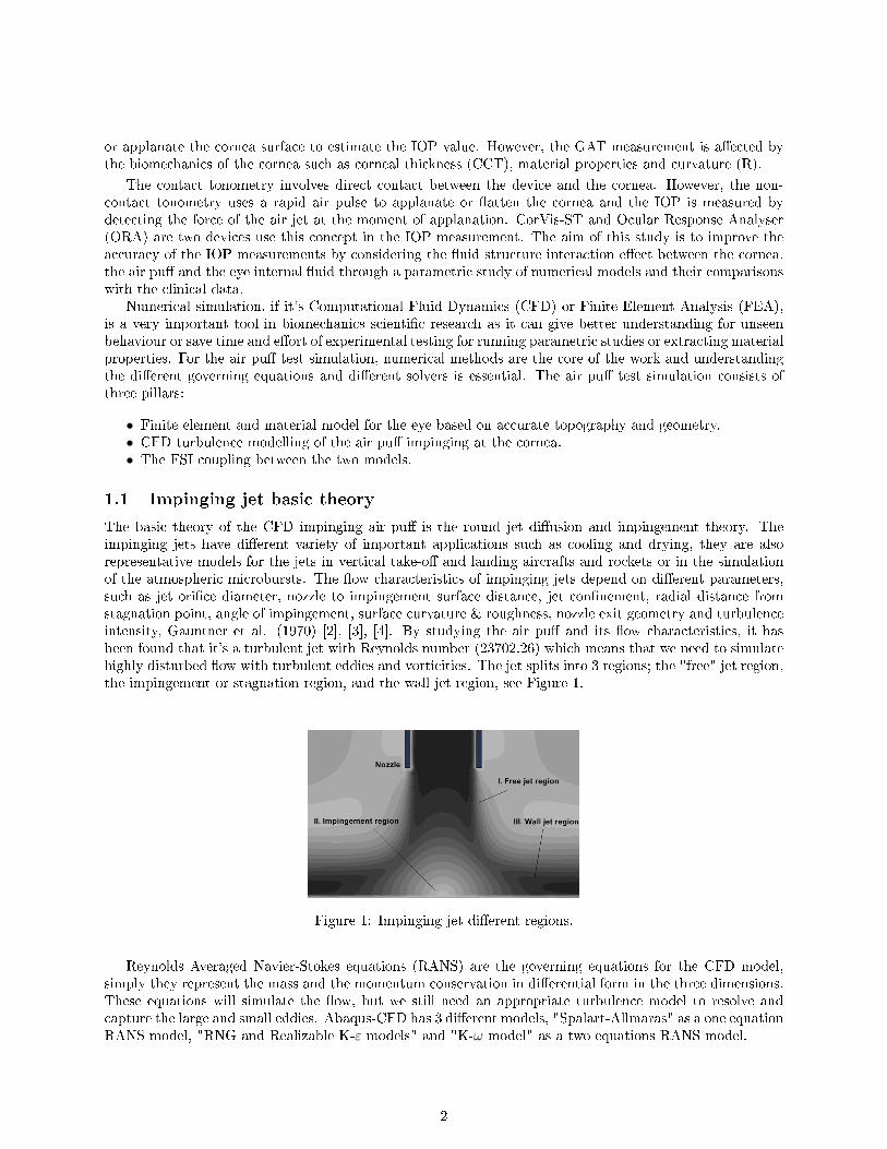
The basic theory of the CFD impinging air pu� is the round jet di�usion and impingement theory. Theimpinging jets have di�erent variety of important applications such as cooling and drying, they are alsorepresentative models for the jets in vertical take-o� and landing aircrafts and rockets or in the simulationof the atmospheric microbursts. The �ow characteristics of impinging jets depend on di�erent parameters,such as jet ori�ce diameter, nozzle to impingement surface distance, jet con�nement, radial distance fromstagnation point, angle of impingement, surface curvature & roughness, nozzle exit geometry and turbulenceintensity, Gauntner et al. (1970) [2], [3], [4]. By studying the air pu� and its �ow characteristics, it hasbeen found that it's a turbulent jet with Reynolds number (23702.26) which means that we need to simulatehighly disturbed �ow with turbulent eddies and vorticities. The jet splits into 3 regions; the "free" jet region,the impingement or stagnation region, and the wall-jet region, see Figure 1.
Figure 1: Impinging jet di�erent regions.
Reynolds Averaged Navier-Stokes equations (RANS) are the governing equations for the CFD model,simply they represent the mass and the momentum conservation in di�erential form in the three dimensions.These equations will simulate the �ow, but we still need an appropriate turbulence model to resolve andcapture the large and small eddies. Abaqus-CFD has 3 di�erent models, "Spalart-Allmaras" as a one equationRANS model, "RNG and Realizable K-ε models" and "K-ω model" as a two equations RANS model.
2

1.2 Aeroelasticity
Aeroelasticity deals with the combined features of �uid mechanics and solid mechanics. There are manyapplications based on this part of science such as aircraft's wing design, turbo-machinery, bridges andskyscrapers design, electric transmission lines, arti�cial heart valves, respiratory mechanics and is consideredas the foundation of the modern biomechanics. In most of the aeroelasticity applications, it's normallyassumed that the external loading acting on a structure is, in general, independent of the deformation ofthat structure and this was the assumption made in the literature when simulating the air pu� test, butactually the deformations of the cornea are in an order of magnitude which can't be ignored comparedto the eye and the cornea size and it will have e�ect on the applied aerodynamic force by the air jet.The key reference dimensionless number in specifying the kind of the FSI problem is the Reduced Velocity
UR =TSolid
TFluidwhich is the ratio between the two time scales of the coupled models. In the air pu� test
UR is in order of magnitude from (0 to 10) which is close to the displacement number of the structuremodel (0.054). This range of the reduced velocity is the range of the general aeroelasticity problem whichrequire full coupling and consideration of both time scales during the solution and solving the two modelssimultaneously at the same time. The quasi-static and pseudo-static aeroelasticity approaches will have agreat impact on the accuracy of the solution as there is no model dominant over the other.
Figure 2: The classi�cation of aeroelasticity problems based on the reduced velocity UR.
2 Numerical simulation methodology
The three main parts of the air pu� test simulation are the eye model, the CFD model of the air jet and theFSI coupling between them. The process starts by modelling the CFD model of the air jet �rst and makingsure that it's working separately without any coupling or interfaces and considering the cornea as no-slipwall boundary condition. Then, the �nite element model of the eye is coupled with the CFD turbulent modelof the air pu� exchanging the characteristic variables between them at every time step of the job as shownin �gure 3.
2.1 CFD setup
The air domain geometry, �gure 4 has been generated by Matlab code to project the coordinates of thecornea and three rings from the sclera into layers above the eye model till we reach a distance of 11 mmwhich is the typical distance for the test on real patients. Then, the �uid material properties are de�ned as
3
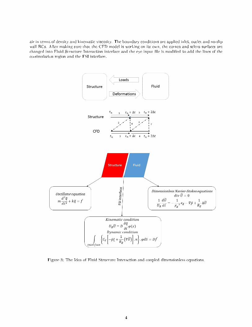
air in terms of density and kinematic viscosity. The boundary conditions are applied inlet, outlet and no-slipwall BCs. After making sure that the CFD model is working on its own, the cornea and sclera surfaces arechanged into Fluid Structure Interaction interface and the eye input �le is modi�ed to add the lines of theco-simulation region and the FSI interface.
Figure 3: The Idea of Fluid Structure Interaction and coupled dimensionless equations.
4
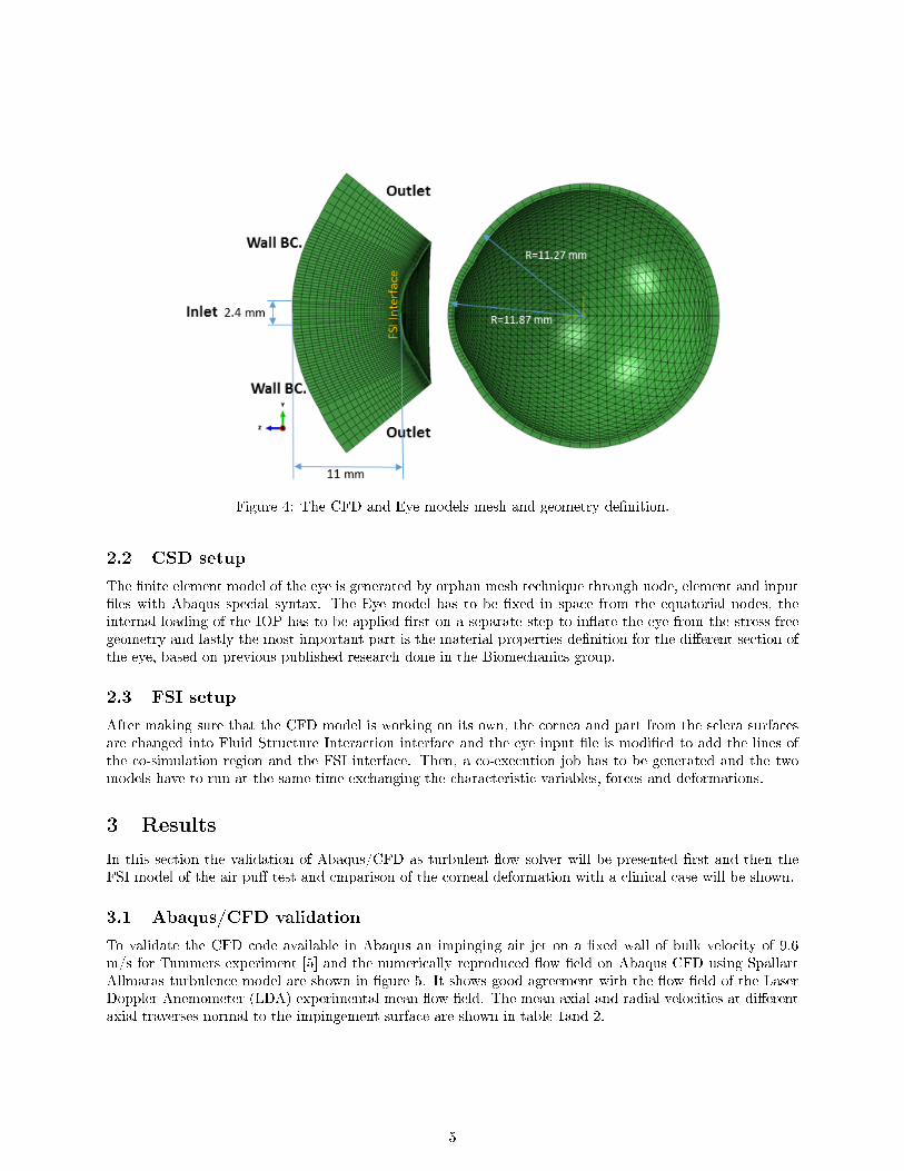
Figure 4: The CFD and Eye models mesh and geometry de�nition.
2.2 CSD setup
The �nite element model of the eye is generated by orphan mesh technique through node, element and input�les with Abaqus special syntax. The Eye model has to be �xed in space from the equatorial nodes, theinternal loading of the IOP has to be applied �rst on a separate step to in�ate the eye from the stress freegeometry and lastly the most important part is the material properties de�nition for the di�erent section ofthe eye, based on previous published research done in the Biomechanics group.
2.3 FSI setup
After making sure that the CFD model is working on its own, the cornea and part from the sclera surfacesare changed into Fluid Structure Interaction interface and the eye input �le is modi�ed to add the lines ofthe co-simulation region and the FSI interface. Then, a co-execution job has to be generated and the twomodels have to run at the same time exchanging the characteristic variables, forces and deformations.
3 Results
In this section the validation of Abaqus/CFD as turbulent �ow solver will be presented �rst and then theFSI model of the air pu� test and cmparison of the corneal deformation with a clinical case will be shown.
3.1 Abaqus/CFD validation
To validate the CFD code available in Abaqus an impinging air jet on a �xed wall of bulk velocity of 9.6m/s for Tummers experiment [5] and the numerically reproduced �ow �eld on Abaqus CFD using SpallartAllmaras turbulence model are shown in �gure 5. It shows good agreement with the �ow �eld of the LaserDoppler Anemometer (LDA) experimental mean �ow �eld. The mean axial and radial velocities at di�erentaxial traverses normal to the impingement surface are shown in table 1and 2.
5
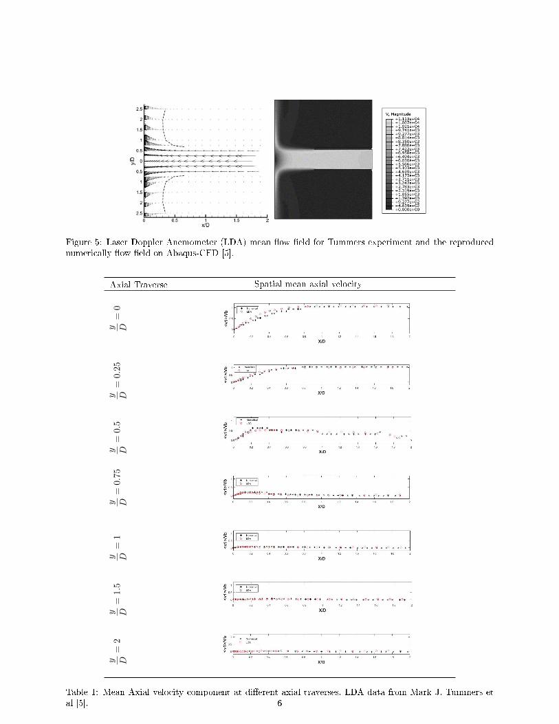
Figure 5: Laser Doppler Anemometer (LDA) mean �ow �eld for Tummers experiment and the reproducednumerically �ow �eld on Abaqus-CFD [5].
Axial Traverse Spatial mean axial velocity
y D=
0y D
=0.25
y D=
0.5
y D=
0.75
y D=
1y D
=1.5
y D=
2
Table 1: Mean Axial velocity component at di�erent axial traverses, LDA data from Mark J. Tummers etal [5]. 6
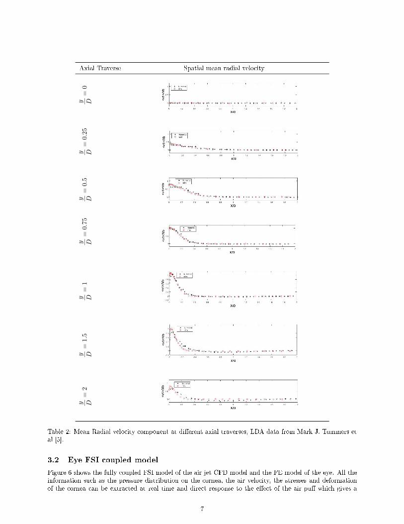
Axial Traverse Spatial mean radial velocity
y D=
0y D
=0.25
y D=
0.5
y D=
0.75
y D=
1y D
=1.5
y D=
2
Table 2: Mean Radial velocity component at di�erent axial traverses, LDA data from Mark J. Tummers etal [5].
3.2 Eye FSI coupled model
Figure 6 shows the fully coupled FSI model of the air jet CFD model and the FE model of the eye. All theinformation such as the pressure distribution on the cornea, the air velocity, the stresses and deformationof the cornea can be extracted at real time and direct response to the e�ect of the air pu� which gives a
7
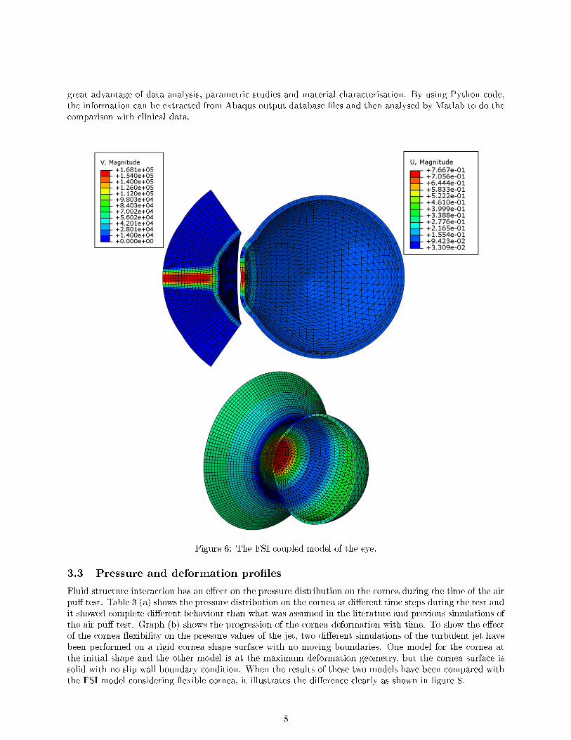
great advantage of data analysis, parametric studies and material characterisation. By using Python code,the information can be extracted from Abaqus output database �les and then analysed by Matlab to do thecomparison with clinical data.
Figure 6: The FSI coupled model of the eye.
3.3 Pressure and deformation pro�les
Fluid structure interaction has an e�ect on the pressure distribution on the cornea during the time of the airpu� test. Table 3 (a) shows the pressure distribution on the cornea at di�erent time steps during the test andit showed complete di�erent behaviour than what was assumed in the literature and previous simulations ofthe air pu� test. Graph (b) shows the progression of the cornea deformation with time. To show the e�ectof the cornea �exibility on the pressure values of the jet, two di�erent simulations of the turbulent jet havebeen performed on a rigid cornea shape surface with no moving boundaries. One model for the cornea atthe initial shape and the other model is at the maximum deformation geometry, but the cornea surface issolid with no slip wall boundary condition. When the results of these two models have been compared withthe FSI model considering �exible cornea, it illustrates the di�erence clearly as shown in �gure 8.
8
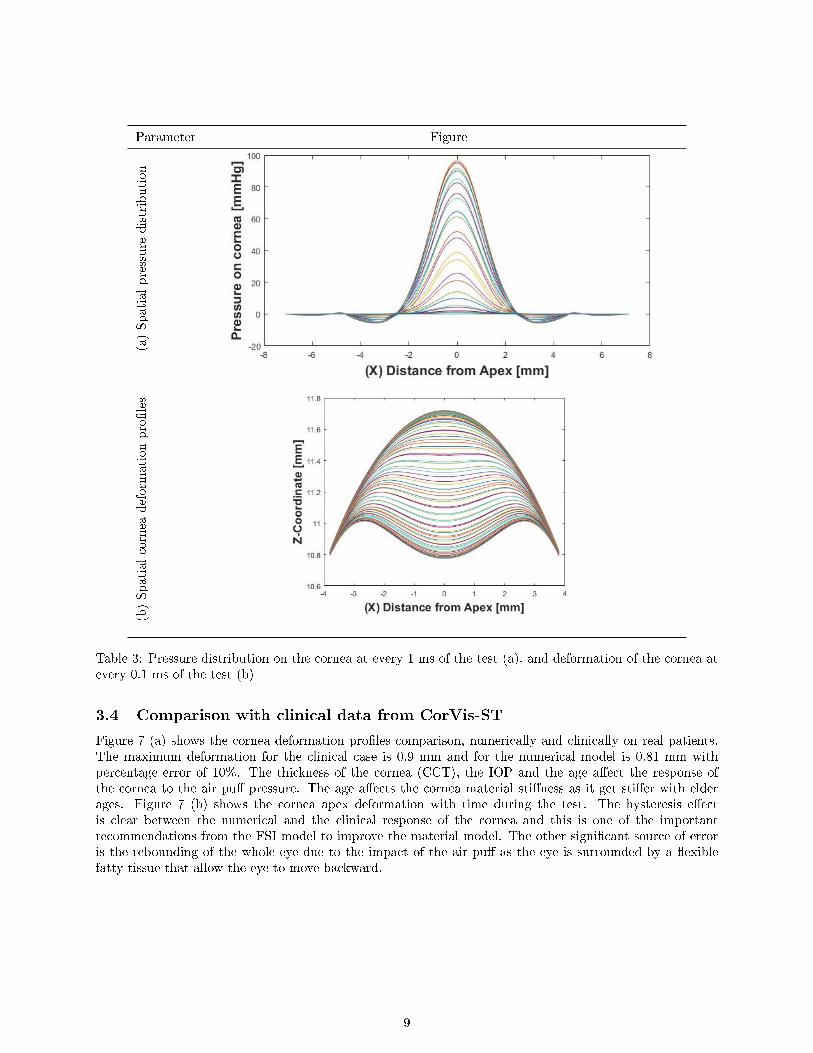
Parameter Figure(a)Spatialpressure
distribution
(b)Spatialcornea
deform
ation
pro�les
Table 3: Pressure distribution on the cornea at every 1 ms of the test (a), and deformation of the cornea atevery 0.1 ms of the test (b)
3.4 Comparison with clinical data from CorVis-ST
Figure 7 (a) shows the cornea deformation pro�les comparison, numerically and clinically on real patients.The maximum deformation for the clinical case is 0.9 mm and for the numerical model is 0.81 mm withpercentage error of 10%. The thickness of the cornea (CCT), the IOP and the age a�ect the response ofthe cornea to the air pu� pressure. The age a�ects the cornea material sti�ness as it get sti�er with elderages. Figure 7 (b) shows the cornea apex deformation with time during the test. The hysteresis e�ectis clear between the numerical and the clinical response of the cornea and this is one of the importantrecommendations from the FSI model to improve the material model. The other signi�cant source of erroris the rebounding of the whole eye due to the impact of the air pu� as the eye is surrounded by a �exiblefatty tissue that allow the eye to move backward.
9
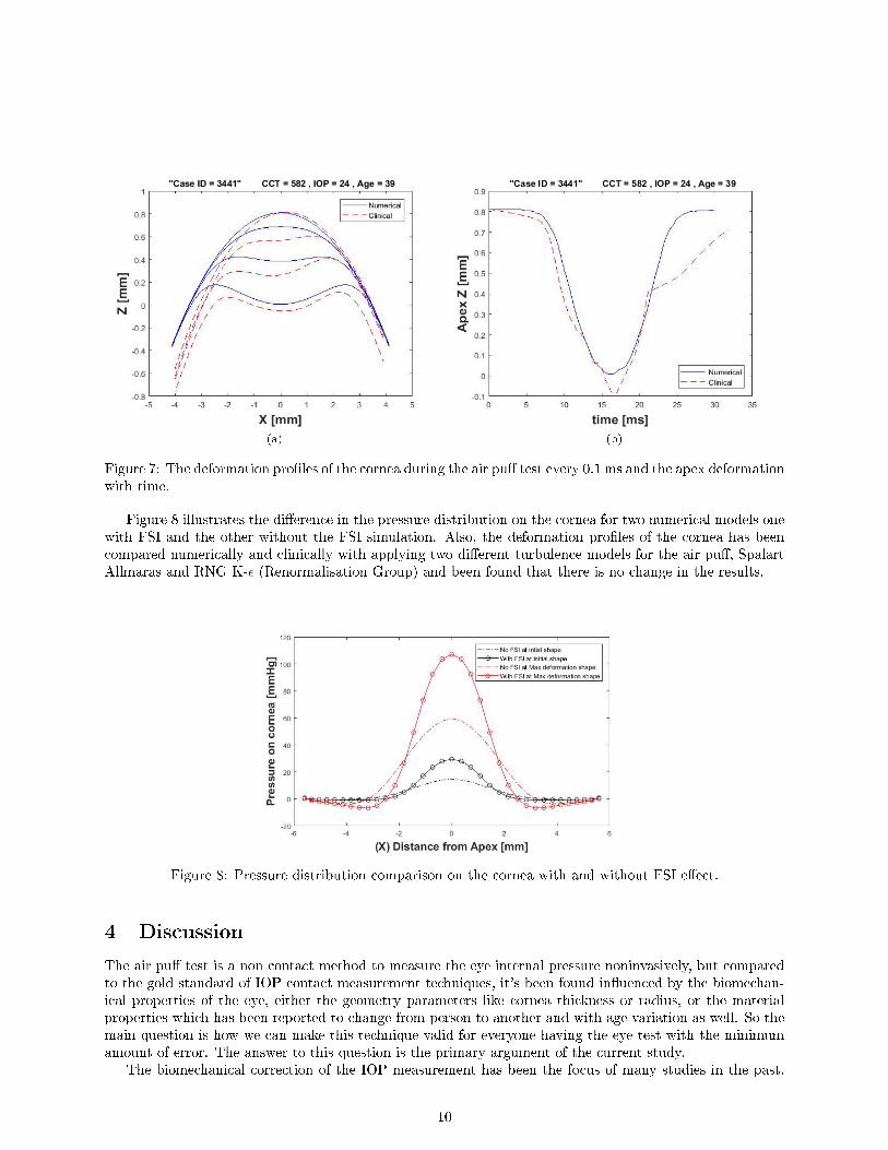
(a) (b)
Figure 7: The deformation pro�les of the cornea during the air pu� test every 0.1 ms and the apex deformationwith time.
Figure 8 illustrates the di�erence in the pressure distribution on the cornea for two numerical models onewith FSI and the other without the FSI simulation. Also, the deformation pro�les of the cornea has beencompared numerically and clinically with applying two di�erent turbulence models for the air pu�, SpalartAllmaras and RNG K-ε (Renormalisation Group) and been found that there is no change in the results.
Figure 8: Pressure distribution comparison on the cornea with and without FSI e�ect.
4 Discussion
The air pu� test is a non contact method to measure the eye internal pressure noninvasively, but comparedto the gold standard of IOP contact measurement techniques, it's been found in�uenced by the biomechan-ical properties of the eye, either the geometry parameters like cornea thickness or radius, or the materialproperties which has been reported to change from person to another and with age variation as well. So themain question is how we can make this technique valid for everyone having the eye test with the minimumamount of error. The answer to this question is the primary argument of the current study.
The biomechanical correction of the IOP measurement has been the focus of many studies in the past.
10

Some studies focused on the association of the IOP with the cornea CCT and Radius, other studies studiedthe material properties e�ect, but most of the them were structural in nature with no su�cient attention tothe �uid structure interaction e�ect during the air pu� test, especially due to the fact that the corneal tissueis bounded by two �uids, the air jet from outside and the aqueous and vitreous humour from inside. Thisis considered a signi�cant �uid mechanics analysis which can't be simpli�ed or perform the structural andmaterial analysis based on assumptions on the �uid interaction with the material. Some of these assumptionscan work e�ectively if the ratio between the time scales of the two physics is very small or very large toneglect the e�ect of one domain over the other or make a reasonable approximation, this ratio is knownas the reduced velocity (UR). But this is not the case in the air pu� test as the two time scales of the�uid velocity and the eye deformations are within the same order of magnitude and changing through theunsteady application of the air jet on the cornea during the test. That's the core of any �uid structureinteraction problem classi�cation as there are plenty of applications and numerical methods speci�c to eachkind of problem.
The numerical analysis of the turbulent impinging jet has been done in the context of hybrid �nite volumesolution of Navier-Stokes equations and Spallart allmaras or RNG-k epsilon turbulence models to simulatethe production and dissipation of the turbulent kinetic energy which will produce an approximate solutionfor the pressure and the velocity �elds over the cornea surface. The produced solution for the pressuredistribution on the cornea and its progression with time is a signi�cant improvement in the understanding ofthe change of the pressure with time during the test compared to what have been assumed in the literature.
The numerical analysis of the �nite element model of the eye has been done based on the context of theprevious research conducted at the Biomechanics group. It uses the Galerkin mean weighted residual methodto calculate the global sti�ness matrix and then calculate the deformation of the nodes. The approximationon the air pu� pressure was based on a constant pressure loading at the di�erent rings of the cornea changingin magnitude during the time of the test. This pressure distribution is provided by Oculus based on thepressure tranceducer reading inside the cylinder and the pressure on the cornea is been approximated to behalf of the piston pressure [6].
5 Conclusion and Future Work
The complete coupling between the model of the eye and the air model has been accomplished also meshindependence test, boundary conditions independence test. A parametric study is required to be doneto see the e�ect of the corneal biomechanical parameters on the IOP measurements and come up with abiomechanically corrected equation. The next required work is to compare these numerical results with moreexperimental data from human and porcine eyes. Once we validate this model, this will open the doors forinverse analysis to get the right material properties of the cornea or to consider the corneal hysteresis andgain better understanding of the cornea behaviour under loading by testing diseased cornea such as cornealectasia or corneas after and before cross linking. Also, the simulation of the orbit and the fatty tissue aroundthe eye is recommended to reach with the eye model to a higher level of accuracy.
References
[1] Harry A. Quigley. Glaucoma. Lancet, 377:1367�1377, 2011.[2] JW Gauntner, John N B Livingood, and P Hrycak. Survey of literature on �ow characteristics of a
single turbulent jet impinging on a �at plate. Washington, DC, (February):43, 1970.[3] Coleman Dup D and D S Snedeker. A study of free jet impingement. Part 1. Mean properties of free
and impinging jets. Journal of Fluid Mechanics, 45(2):281�319, 1971.[4] Khaled J. Hammad and Ivana Milanovic. Flow Structure in the Near-Wall Region of a Submerged
Impinging Jet. Journal of Fluids Engineering, 133(9):091205, 2011.[5] Mark J. Tummers, Jeroen Jacobse, and Sebastiaan G J Voorbrood. Turbulent �ow in the near �eld of
a round impinging jet. International Journal of Heat and Mass Transfer, 54(23-24):4939�4948, 2011.[6] Akram Abdelazim Joda, Mir Mohi Sefat Shervin, Daniel Kook, and Ahmed Elsheikh. Development
and validation of a correction equation for corvis tonometry. Computer Methods in Biomechanics andBiomedical Engineering, 19(9):943�953, 2016. PMID: 27049961.
11
[7] N. Rajaratnam, D. Z. Zhu, and S. P. Rai. Turbulence measurements in the impinging region of a circularjet. Canadian Journal of Civil Engineering, 37(2002):782�786, 2010.
[8] D. Cooper, D. C. Jackson, B. E. Launder, and G. X. Liao. Impinging jet studies for turbulence modelassessment-I. Flow-�eld experiments. International Journal of Heat and Mass Transfer, 36(10):2675�2684, 1993.
[9] Hussein J. Hussein, Steven P. Capp, and William K. George. Velocity measurements in a high-Reynolds-number, momentum-conserving, axisymmetric, turbulent jet. Journal of Fluid Mechanics, 258(1994):31�75, 1994.
[10] Ahmed Elsheikh, Defu Wang, Aachal Kotecha, Michael Brown, and David Garway-Heath. Evaluation ofGoldmann applanation tonometry using a nonlinear �nite element ocular model. Annals of BiomedicalEngineering, 34(10):1628�40, oct 2006.
[11] Ahmed Elsheikh, Defu Wang, and David Pye. Determination of the modulus of elasticity of the humancornea. Journal of refractive surgery (Thorofare, N.J. : 1995), 23(8):808�18, oct 2007.
[12] Aachal Kotecha, Ahmed Elsheikh, Cynthia R Roberts, Haogang Zhu, and David F Garway-Heath.Corneal thickness- and age-related biomechanical properties of the cornea measured with the ocularresponse analyzer. Investigative ophthalmology & visual science, 47(12):5337�47, dec 2006.
[13] P G Davey, a Elsheikh, and D F Garway-Heath. Clinical evaluation of multiparameter correctionequations for Goldmann applanation tonometry. Eye (London, England), (January):1�9, mar 2013.
[14] Ahmed Elsheikh, Pinakin Gunvant, Stephen W Jones, David Pye, and David Garway-Heath. Correctionfactors for Goldmann Tonometry. Journal of glaucoma, 22(2):156�63, feb 2013.
[15] Ahmed Elsheikh, Daad Alhasso, Aachal Kotecha, and David Garway-Heath. Assessment of the ocularresponse analyzer as a tool for intraocular pressure measurement. Journal of biomechanical engineering,131(8):081010, aug 2009.
[16] Craig Boote, Joel R Palko, Thomas Sorensen, Ashkan Mohammadvali, Ahmed Elsheikh, and M András.Changes in posterior scleral collagen microstructure in canine eyes with an ADAMTS10 mutation.10(November 2015):503�517, 2016.
[17] Mohammad Arsalan Khan. Numerical study on human cornea and modi�ed multiparametric correc-tion equation for Goldmann applanation tonometer. Journal of the mechanical behavior of biomedicalmaterials, 30:91�102, feb 2014.
[18] Michael Sullivan-Mee, Sarah E Lewis, Denise Pensyl, Gretchen Gerhardt, Kathy D Halverson, andCli�ord Qualls. Factors In�uencing Intermethod Agreement Between Goldmann Applanation, PascalDynamic Contour, and Ocular Response Analyzer Tonometry. Journal of glaucoma, 00(00):1�9, mar2012.
[19] Original Article. EVALUATING THE MATERIAL PARAMETERS OF THE HUMAN r Fo Pe er Revi ew Fo r P ee r R. 2009.
[20] Andrew S H Tsai and Seng Chee Loon. Intraocular pressure assessment after laser in situ keratomileusis:a review. Clinical & experimental ophthalmology, 40(3):295�304, apr 2012.
[21] Javier Moreno-Montañés, Miguel J Maldonado, Noelia García, Loreto Mendiluce, Pio J García-Gómez,and María Seguí-Gómez. Reproducibility and clinical relevance of the ocular response analyzer innonoperated eyes: corneal biomechanical and tonometric implications. Investigative ophthalmology &visual science, 49(3):968�74, mar 2008.
[22] H Studer, X Larrea, H Riedwyl, and P Büchler. Biomechanical model of human cornea based on stromalmicrostructure. Journal of biomechanics, 43(5):836�42, mar 2010.
[23] Visual Science, Wai Lun, Ka Kit, and Visual Sciences. r Fo ew On r Fo Re ew On ly. 2011.[24] FangJun Bao, ManLi Deng, QinMei Wang, JinHai Huang, Jing Yang, Charles Whitford, Brendan
Geraghty, AYong Yu, and Ahmed Elsheikh. Evaluation of the relationship of corneal biomechanicalmetrics with physical intraocular pressure and central corneal thickness in ex vivo rabbit eye globes.Experimental Eye Research, 137(August):11�17, 2015.
[25] K Anderson, a El-Sheikh, and T Newson. Application of structural analysis to the mechanical behaviourof the cornea. Journal of the Royal Society, Interface / the Royal Society, 1(1):3�15, nov 2004.
[26] Etsuo Chihara. Assessment of true intraocular pressure: the gap between theory and practical data.Survey of ophthalmology, 53(3):203�18, 2008.
[27] Ahmed Elsheikh, Brendan Geraghty, Daad Alhasso, Jonathan Knappett, Marino Campanelli, and PaoloRama. Regional variation in the biomechanical properties of the human sclera. Experimental Eye
12
Research, 90(5):624�33, may 2010.[28] Sabine Kling, Nandor Bekesi, Carlos Dorronsoro, Daniel Pascual, and Susana Marcos. Corneal Vis-
coelastic Properties from Finite-Element Analysis of In Vivo Air-Pu� Deformation. 9(8), 2014.[29] Alfonso Pé, Jos Requejo, Requejo Isidro, and Susana Marcos. Corneal Deformation in an In�ation
Porcine Corneal Model Measured with Scheimp�ug Imaging Conclusions. 2008.[30] Xiaoyu Liu, Lizhen Wang, Jing Ji, Wei Yao, Wei Wei, Jie Fan, Shailesh Joshi, Deyu Li, and Yubo Fan.
A Mechanical Model of the Cornea Considering the Crimping Morphology of Collagen Fibrils. 2013.[31] David P. Piñero and Natividad Alcón. In vivo characterization of corneal biomechanics. Journal of
Cataract and Refractive Surgery, 40(6):870�887, 2014.[32] Christopher Kai-Shun Leung, Cong Ye, and Robert N Weinreb. An ultra-high-speed Scheimp�ug camera
for evaluation of corneal deformation response and its impact on IOP measurement. Investigativeophthalmology & visual science, 54(4):2885�92, apr 2013.
[33] Aachal Kotecha, David P Crabb, Alexander Spratt, and David F Garway-Heath. The relationshipbetween diurnal variations in intraocular pressure measurements and central corneal thickness andcorneal hysteresis. Investigative ophthalmology & visual science, 50(9):4229�36, sep 2009.
[34] Chuanqing Zhou Zhaolong, Han, Dai, Zhou. Air Pu� Induced Corneal Vibrations : Theoretical. (August2015), 2014.
[35] Ian a Sigal, Richard a Bilonick, Larry Kagemann, Gadi Wollstein, Hiroshi Ishikawa, Joel S Schuman, andJonathan L Grimm. The optic nerve head as a robust biomechanical system. Investigative ophthalmology& visual science, 53(6):2658�67, may 2012.
[36] Ahmed Elsheikh and Defu Wang. Numerical modelling of corneal biomechanical behaviour. Computermethods in biomechanics and biomedical engineering, 10(2):85�95, apr 2007.
[37] Keith M Meek and Craig Boote. The use of X-ray scattering techniques to quantify the orientation anddistribution of collagen in the corneal stroma. Progress in retinal and eye research, 28(5):369�92, sep2009.
[38] Shang Wang, Jiasong Li, Ravi Kiran Manapuram, Floredes M Menodiado, R Davis, Michael D Twa,Alexander J Lazar, Dina C Lev, and Raphael E Pollock. HHS Public Access. 37(24):5184�5186, 2015.
[39] David R Lari, David S Schultz, Aaron S Wang, On-Tat Lee, and Jay M Stewart. Scleral mechanics:comparing whole globe in�ation and uniaxial testing. Experimental eye research, 94(1):128�35, jan 2012.
[40] Meixiao Shen, Fan Fan, Anquan Xue, Jianhua Wang, Xiangtian Zhou, and Fan Lu. Biomechanicalproperties of the cornea in high myopia. Vision research, 48(21):2167�71, sep 2008.
[41] Ahmed Elsheikh, Defu Wang, Michael Brown, Paolo Rama, Marino Campanelli, and David Pye. As-sessment of corneal biomechanical properties and their variation with age. Current Eye Research,32(1):11�19, jan 2007.
[42] Andrew Lam, Davie Chen, Roger Chiu, and Wan-Sang Chui. Comparison of IOP measurements betweenORA and GAT in normal Chinese. Optometry and vision science : o�cial publication of the AmericanAcademy of Optometry, 84(9):909�14, sep 2007.
[43] Ahmed Elsheikh, Wael Kassem, and Stephen W Jones. Strain-rate sensitivity of porcine and ovinecorneas. Acta of bioengineering and biomechanics / Wrocªaw University of Technology, 13(2):25�36, jan2011.
[44] Aurélie Benoit, Gaël Latour, Schanne-Klein Marie-Claire, and Jean-Marc Allain. Simultaneous mi-crostructural and mechanical characterization of human corneas at increasing pressure. Journal of theMechanical Behavior of Biomedical Materials, 60:93�105, 2016.
[45] Ahmed Elsheikh, Charles W. McMonnies, Charles Whitford, and Gavin C. Boneham. In vivo study ofcorneal responses to increased intraocular pressure loading. Eye and Vision, 2(1):20, 2015.
[46] Kristin M Myers, Frances E Cone, Harry a Quigley, Scott Gelman, Mary E Pease, and Thao D Nguyen.The in vitro in�ation response of mouse sclera. Experimental eye research, 91(6):866�75, dec 2010.
[47] David Touboul, Cynthia Roberts, Julien Kérautret, Caroline Garra, Sylvie Maurice-Tison, ElodieSaubusse, and Joseph Colin. Correlations between corneal hysteresis, intraocular pressure, and cornealcentral pachymetry. Journal of cataract and refractive surgery, 34(4):616�22, apr 2008.
[48] Abhijit Sinha Roy andWilliam J Dupps. Patient-speci�c modeling of corneal refractive surgery outcomesand inverse estimation of elastic property changes. Journal of biomechanical engineering, 133(1):011002,jan 2011.
[49] Charles W McMonnies. Assessing corneal hysteresis using the Ocular Response Analyzer. Optometry
13
and vision science : o�cial publication of the American Academy of Optometry, 89(3):E343�9, mar2012.
[50] Benjamin Cruz Perez, Hugh J Morris, Richard T Hart, and Jun Liu. Finite element modeling of theviscoelastic responses of the eye during microvolumetric changes. Journal of biomedical science andengineering, 6(12A):29�37, dec 2013.
[51] Ahmed Elsheikh, DefuWang, Paolo Rama, Marino Campanelli, and David Garway-Heath. Experimentalassessment of human corneal hysteresis. Current Eye Research, 33(3):205�13, mar 2008.
[52] Bodies Mechanics and Biomedical Sciences. r Fo vi ew On Fo r R iew On ly. 2009.[53] David Pye, Vision Science, and Ocular Response Analyser. Title page. 3424:1�26, 2011.[54] Visual Science. r Fo ew On r Fo Re ew On ly. 2010.[55] Ying Hon and Andrew K C Lam. Corneal deformation measurement using Scheimp�ug noncontact
tonometry. Optometry and vision science : o�cial publication of the American Academy of Optometry,90(1):e1�8, jan 2013.
[56] Steven J Petsche and Peter M Pinsky. The role of 3-D collagen organization in stromal elasticity:a model based on X-ray di�raction data and second harmonic-generated images. Biomechanics andmodeling in mechanobiology, (1938), jan 2013.
[57] Ian C Campbell. Biomechanics of the Posterior Eye : A Critical Role in Health and Disease. 136(Febru-ary 2014), 2016.
[58] K M Meek. The Cornea and Sclera. 2008.[59] Jun Liu and Xiaoyin He. Corneal sti�ness a�ects IOP elevation during rapid volume change in the eye.
Investigative ophthalmology & visual science, 50(5):2224�9, may 2009.
14


![JCAMECH€¦ · Fluid-structure interaction (FSI) problems are of great important in fluid dynamics[1]. It is also used in biomechanics problems [2,3]. The immersed boundary method](https://img.pdfslide.us/doc/110x75/5f70086f835e2d6e182bad78/jcamech-fluid-structure-interaction-fsi-problems-are-of-great-important-in-fluid.jpg)