Embed Size (px)
Citation preview
1
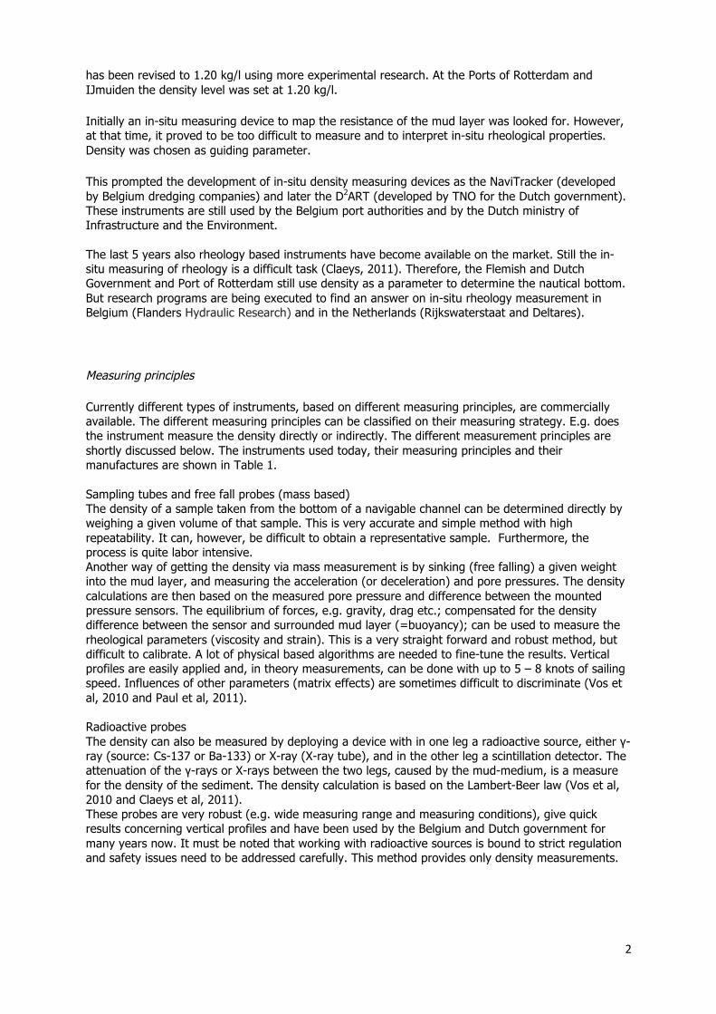
Fluid mud density determination in navigational channels Stijn, Claeys ([email protected]), Belgium Flanders Hydraulic Research (www.watlab.be) Ben, Dierikx ([email protected]), The Netherlands Ministry of Infrastructure and the Environment, Rijkswaterstaat (www.rijkswaterstaat.nl/en/) Simon, Paul ([email protected]), The Netherlands Ministry of Infrastructure and the Environment, Rijkswaterstaat (www.rijkswaterstaat.nl/en/) Jeroen, van Reenen ([email protected]), The Netherlands Port of Rotterdam (www.portofrotterdam.com) Topic H: geophysics of the marine environment
Introduction
Cohesive sediment management in navigable channels and harbors needs to be tackled in a cost-effective and safe way. The sedimentation and consolidation of sediments is a natural driven continuous process which needs to be controlled. The forming of mud layers are driven by time dependent natural hydraulic conditions, ambient conditions and sediment input. Also harbor and dredging activities will alter the mud layer in thickness and its rheological behavior. Depending on the composition, time and ambient conditions the mud will build up strength and will become non-navigable at a certain level.
Dredging the whole mud layer is not needed because part of the mud layer is fluid enough to sail through it. This requires the mapping of the mud layer properties. But, not only the total mud-body needs to be mapped, also a vertical picture of its strength is needed. The strength behavior of the mud is depending on the applied deformation force and time. In-situ measuring of the reaction against deformation of the mud is a very difficult task, therefore another site-related parameter, density, is measured instead. The whole monitoring scope is a difficult exercise between a correct measurement, reducing dredging cost and guarantying a safe vessel passage.
In the last few years, researchers of the Flanders Hydraulic Research (Flemish Government), the Port of Rotterdam, the Dutch Ministry of Infrastructure and Environment and third party manufactures have evaluated existing and new methods for the determination of the density of fluid mud. Different methods were analyzed on their physical principles, tested in a laboratory and tested in the field. This paper discusses the main results and conclusions. But first a brief description of the history of measuring the density of fluid mud is given.
Brief description of the history of measuring the density of fluid mud
In the 70ties and 80ties of the 20th century extensive research was carried out to map the nautical bottom1, with the aim to reduce dredging costs. Research was carried out to determine the non-navigable mud layer, which needs to be brought to the target level of the harbor. This was done in Belgium, the Netherlands, Germany and many other countries. It was found that the mud density was the best (guiding) parameter. The nautical bottom density level was, however, different for every port. Guidelines and limits were documented in PIANC guidelines (PIANC, 1997). In Belgium in the 80ties, physical scale modeling (at Flanders Hydraulics Research), mathematical modeling and real scale in-situ navigation tests were used to determine the nautical depth. Also large sampling campaigns together with rheology, density and other sediment related laboratory tests were executed. Comparable test programs were also carried out in the port of Rotterdam. Based on these tests, in Zeebrugge the nautical bottom was determined at 1.15 kg/l. Later, in 2001, the density level 1 The nautical bottom is defined as the level where the physical characteristics reach a critical limit beyond which contact with a ship’s keel causes either damage or unacceptable effects on controllability and maneuverability (PIANC, 1997).
2
has been revised to 1.20 kg/l using more experimental research. At the Ports of Rotterdam and IJmuiden the density level was set at 1.20 kg/l.
Initially an in-situ measuring device to map the resistance of the mud layer was looked for. However, at that time, it proved to be too difficult to measure and to interpret in-situ rheological properties. Density was chosen as guiding parameter.
This prompted the development of in-situ density measuring devices as the NaviTracker (developed by Belgium dredging companies) and later the D2ART (developed by TNO for the Dutch government). These instruments are still used by the Belgium port authorities and by the Dutch ministry of Infrastructure and the Environment. The last 5 years also rheology based instruments have become available on the market. Still the in-situ measuring of rheology is a difficult task (Claeys, 2011). Therefore, the Flemish and Dutch Government and Port of Rotterdam still use density as a parameter to determine the nautical bottom. But research programs are being executed to find an answer on in-situ rheology measurement in Belgium (Flanders Hydraulic Research) and in the Netherlands (Rijkswaterstaat and Deltares).
Measuring principles
Currently different types of instruments, based on different measuring principles, are commercially available. The different measuring principles can be classified on their measuring strategy. E.g. does the instrument measure the density directly or indirectly. The different measurement principles are shortly discussed below. The instruments used today, their measuring principles and their manufactures are shown in Table 1. Sampling tubes and free fall probes (mass based) The density of a sample taken from the bottom of a navigable channel can be determined directly by weighing a given volume of that sample. This is very accurate and simple method with high repeatability. It can, however, be difficult to obtain a representative sample. Furthermore, the process is quite labor intensive. Another way of getting the density via mass measurement is by sinking (free falling) a given weight into the mud layer, and measuring the acceleration (or deceleration) and pore pressures. The density calculations are then based on the measured pore pressure and difference between the mounted pressure sensors. The equilibrium of forces, e.g. gravity, drag etc.; compensated for the density difference between the sensor and surrounded mud layer (=buoyancy); can be used to measure the rheological parameters (viscosity and strain). This is a very straight forward and robust method, but difficult to calibrate. A lot of physical based algorithms are needed to fine-tune the results. Vertical profiles are easily applied and, in theory measurements, can be done with up to 5 – 8 knots of sailing speed. Influences of other parameters (matrix effects) are sometimes difficult to discriminate (Vos et al, 2010 and Paul et al, 2011). Radioactive probes The density can also be measured by deploying a device with in one leg a radioactive source, either γ-ray (source: Cs-137 or Ba-133) or X-ray (X-ray tube), and in the other leg a scintillation detector. The attenuation of the γ-rays or X-rays between the two legs, caused by the mud-medium, is a measure for the density of the sediment. The density calculation is based on the Lambert-Beer law (Vos et al, 2010 and Claeys et al, 2011). These probes are very robust (e.g. wide measuring range and measuring conditions), give quick results concerning vertical profiles and have been used by the Belgium and Dutch government for many years now. It must be noted that working with radioactive sources is bound to strict regulation and safety issues need to be addressed carefully. This method provides only density measurements.
3
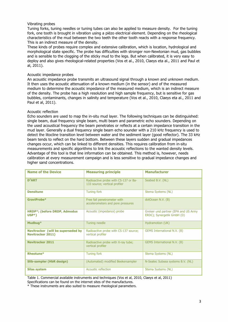
Vibrating probes Tuning forks, tuning needles or tuning tubes can also be applied to measure density. For the tuning fork, one tooth is brought in vibration using a piëzo electrical element. Depending on the rheological characteristics of the mud between the two teeth the other tooth reacts with a response frequency. This is an indirect measure of the density. These kinds of probes require complex and extensive calibration, which is location, hydrological and morphological state specific. The probe has difficulties with stronger non-Newtonian mud, gas bubbles and is sensible to the clogging of the sticky mud to the legs. But when calibrated, it is very easy to deploy and also gives rheological-related properties (Vos et al., 2010, Claeys eta al., 2011 and Paul et al, 2011). Acoustic impedance probes An acoustic impedance probe transmits an ultrasound signal through a known and unknown medium. It then uses the acoustic attenuation of a known medium (in the sensor) and of the measured medium to determine the acoustic impedance of the measured medium, which is an indirect measure of the density. The probe has a high resolution and high sample frequency, but is sensitive for gas bubbles, contaminants, changes in salinity and temperature (Vos et al., 2010, Claeys eta al., 2011 and Paul et al, 2011). Acoustic reflection Echo sounders are used to map the in-situ mud layer. The following techniques can be distinguished: single beam, dual frequency single beam, multi beam and parametric echo sounders. Depending on the used acoustical frequency the beam penetrates or reflects at a certain impedance transition in the mud layer. Generally a dual frequency single beam echo sounder with a 210 kHz frequency is used to detect the litocline transition level between water and the sediment layer (good reflector). The 33 kHz beam tends to reflect on the hard bottom. Between these layers sudden and gradual impedances changes occur, which can be linked to different densities. This requires calibration from in-situ measurements and specific algorithms to link the acoustic reflections to the wanted density levels. Advantage of this tool is that line information can be obtained. This method is, however, needs calibration at every measurement campaign and is less sensitive to gradual impedance changes and higher sand concentrations. Name of the Device Measuring principle Manufacturer
D2ART Radioactive probe with CS-137 or Ba-133 source; vertical profiler
Seabed B.V. (NL)
Densitune Tuning fork Stema Systems (NL)
GraviProbe* Free fall penetrometer with accelerometers and pore pressures
dotOcean N.V. (B)
HRDP*; (before DRDP, Admodus USP*)
Acoustic (impedance) probe Greiser und partner (EPA and US Army ERDC); Synergetik GmbH (D)
Mudbug* Tuning needle Hydramotion (UK)
Navitracker (will be superseded by Navitracker 2011)
Radioactive probe with CS-137 source; vertical profiler
GEMS International N.V. (B)
Navitracker 2011 Radioactive probe with X-ray tube; vertical profiler
GEMS International N.V. (B)
Rheotune* Tuning fork Stema Systems (NL)
Slib-sampler (HbR design) (Automated) modified Beekersampler N-Seatec Subsea systems B.V. (NL)
Silas system Acoustic reflection Stema Systems (NL)
Table 1. Commercial available instruments and techniques (Vos et al, 2010, Claeys et al, 2011) Specifications can be found on the internet sites of the manufactures. * These instruments are also suited to measure rheological parameters.
4
All the above mentioned techniques are probes or echo sounders, except for the slib-sampler and the Silas system, which takes vertical samples.
Laboratory comparison tests at the Sediment Test Tank (STT)
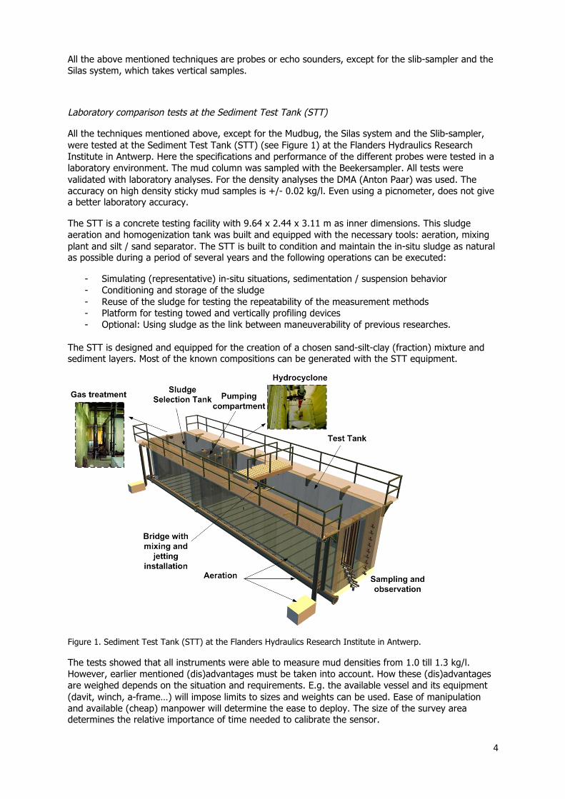
All the techniques mentioned above, except for the Mudbug, the Silas system and the Slib-sampler, were tested at the Sediment Test Tank (STT) (see Figure 1) at the Flanders Hydraulics Research Institute in Antwerp. Here the specifications and performance of the different probes were tested in a laboratory environment. The mud column was sampled with the Beekersampler. All tests were validated with laboratory analyses. For the density analyses the DMA (Anton Paar) was used. The accuracy on high density sticky mud samples is +/- 0.02 kg/l. Even using a picnometer, does not give a better laboratory accuracy.
The STT is a concrete testing facility with 9.64 x 2.44 x 3.11 m as inner dimensions. This sludge aeration and homogenization tank was built and equipped with the necessary tools: aeration, mixing plant and silt / sand separator. The STT is built to condition and maintain the in-situ sludge as natural as possible during a period of several years and the following operations can be executed:
- Simulating (representative) in-situ situations, sedimentation / suspension behavior - Conditioning and storage of the sludge - Reuse of the sludge for testing the repeatability of the measurement methods - Platform for testing towed and vertically profiling devices - Optional: Using sludge as the link between maneuverability of previous researches.
The STT is designed and equipped for the creation of a chosen sand-silt-clay (fraction) mixture and sediment layers. Most of the known compositions can be generated with the STT equipment.
Figure 1. Sediment Test Tank (STT) at the Flanders Hydraulics Research Institute in Antwerp.
The tests showed that all instruments were able to measure mud densities from 1.0 till 1.3 kg/l. However, earlier mentioned (dis)advantages must be taken into account. How these (dis)advantages are weighed depends on the situation and requirements. E.g. the available vessel and its equipment (davit, winch, a-frame…) will impose limits to sizes and weights can be used. Ease of manipulation and available (cheap) manpower will determine the ease to deploy. The size of the survey area determines the relative importance of time needed to calibrate the sensor.
5
Furthermore, the size and weight of the instrument determines the penetration depth. The type of instrument determines the density range. And the choice of the instrument will set its accuracy and its area’s op application.
Finally, it must be stated that different hydraulic conditions will lead to different measuring conditions, were different instruments have different characteristics.
Field tests
Over the years a lot of instruments have been tested. In the last years parties focused on methods which are less labor intensive, are easy to deploy, need less operational and maintainability attention, shorten survey time and give a better spatial resolution.
For this reason recently the Silas system and the D2ART were tested at the Beerkanaal in Rotterdam by Port of Rotterdam and the Ministry of Infrastructure and the Environment
At February 23rd 2012 a comparison test was executed at the Beerkanaal. The goal of this test was to compare the measuring results of the Silas system with the D2ART system and to demonstrate the performance of the Graviprobe. The Silas system was calibrated by samples taken with a modified Beekersampler (Slib-sampler).
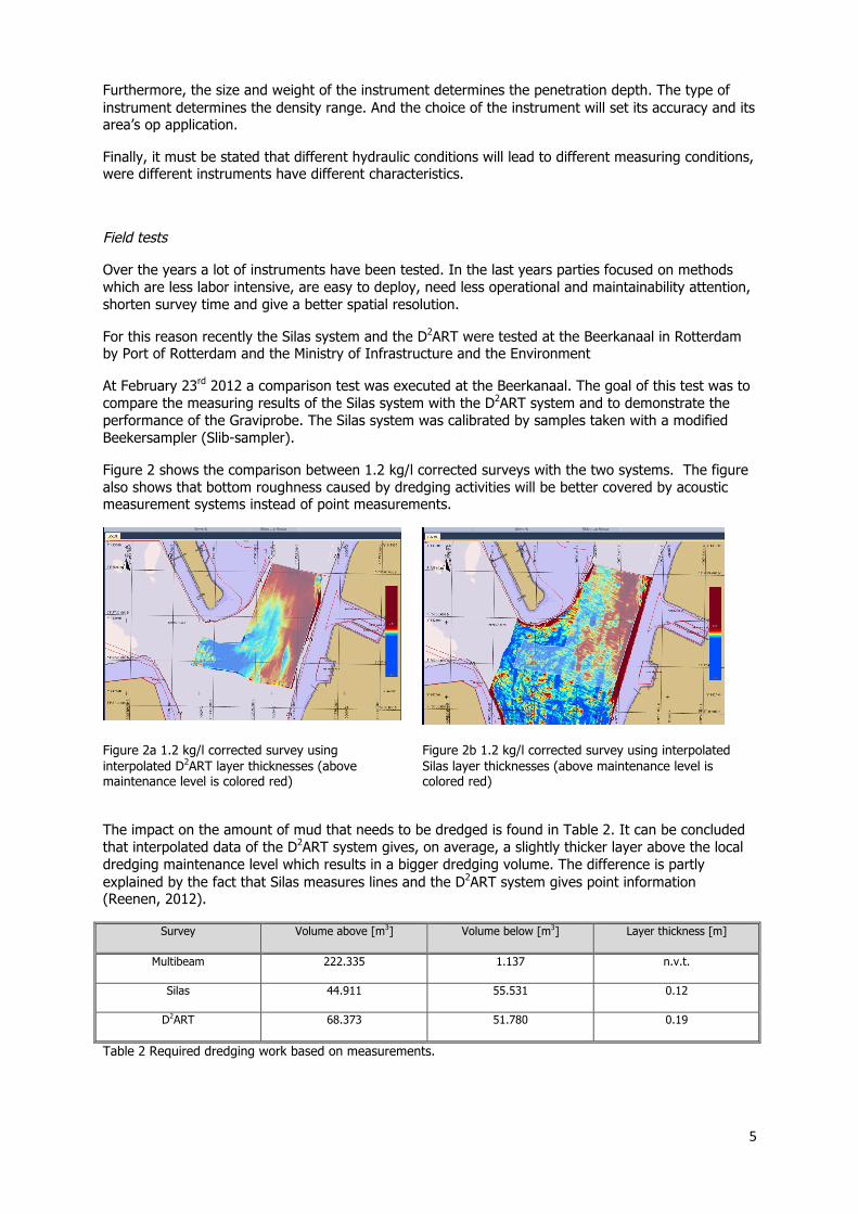
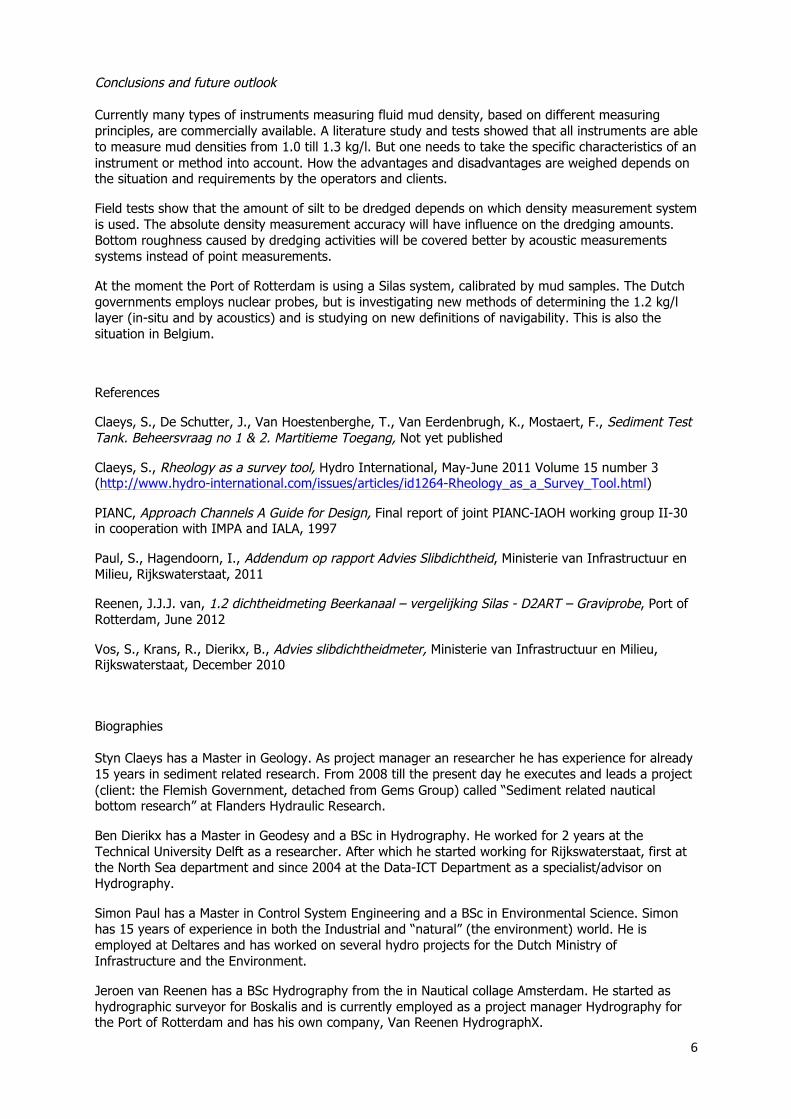
Figure 2 shows the comparison between 1.2 kg/l corrected surveys with the two systems. The figure also shows that bottom roughness caused by dredging activities will be better covered by acoustic measurement systems instead of point measurements.
Figure 2a 1.2 kg/l corrected survey using interpolated D2ART layer thicknesses (above maintenance level is colored red)
Figure 2b 1.2 kg/l corrected survey using interpolated Silas layer thicknesses (above maintenance level is colored red)
The impact on the amount of mud that needs to be dredged is found in Table 2. It can be concluded that interpolated data of the D2ART system gives, on average, a slightly thicker layer above the local dredging maintenance level which results in a bigger dredging volume. The difference is partly explained by the fact that Silas measures lines and the D2ART system gives point information (Reenen, 2012).
Survey Volume above [m3] Volume below [m3] Layer thickness [m]
Multibeam 222.335 1.137 n.v.t.
Silas 44.911 55.531 0.12
D2ART 68.373 51.780 0.19
Table 2 Required dredging work based on measurements.
6
Conclusions and future outlook
Currently many types of instruments measuring fluid mud density, based on different measuring principles, are commercially available. A literature study and tests showed that all instruments are able to measure mud densities from 1.0 till 1.3 kg/l. But one needs to take the specific characteristics of an instrument or method into account. How the advantages and disadvantages are weighed depends on the situation and requirements by the operators and clients.
Field tests show that the amount of silt to be dredged depends on which density measurement system is used. The absolute density measurement accuracy will have influence on the dredging amounts. Bottom roughness caused by dredging activities will be covered better by acoustic measurements systems instead of point measurements.
At the moment the Port of Rotterdam is using a Silas system, calibrated by mud samples. The Dutch governments employs nuclear probes, but is investigating new methods of determining the 1.2 kg/l layer (in-situ and by acoustics) and is studying on new definitions of navigability. This is also the situation in Belgium.
References
Claeys, S., De Schutter, J., Van Hoestenberghe, T., Van Eerdenbrugh, K., Mostaert, F., Sediment Test Tank. Beheersvraag no 1 & 2. Martitieme Toegang, Not yet published
Claeys, S., Rheology as a survey tool, Hydro International, May-June 2011 Volume 15 number 3 (http://www.hydro-international.com/issues/articles/id1264-Rheology_as_a_Survey_Tool.html)
PIANC, Approach Channels A Guide for Design, Final report of joint PIANC-IAOH working group II-30 in cooperation with IMPA and IALA, 1997
Paul, S., Hagendoorn, I., Addendum op rapport Advies Slibdichtheid, Ministerie van Infrastructuur en Milieu, Rijkswaterstaat, 2011
Reenen, J.J.J. van, 1.2 dichtheidmeting Beerkanaal – vergelijking Silas - D2ART – Graviprobe, Port of Rotterdam, June 2012
Vos, S., Krans, R., Dierikx, B., Advies slibdichtheidmeter, Ministerie van Infrastructuur en Milieu, Rijkswaterstaat, December 2010
Biographies
Styn Claeys has a Master in Geology. As project manager an researcher he has experience for already 15 years in sediment related research. From 2008 till the present day he executes and leads a project (client: the Flemish Government, detached from Gems Group) called “Sediment related nautical bottom research” at Flanders Hydraulic Research.
Ben Dierikx has a Master in Geodesy and a BSc in Hydrography. He worked for 2 years at the Technical University Delft as a researcher. After which he started working for Rijkswaterstaat, first at the North Sea department and since 2004 at the Data-ICT Department as a specialist/advisor on Hydrography.
Simon Paul has a Master in Control System Engineering and a BSc in Environmental Science. Simon has 15 years of experience in both the Industrial and “natural” (the environment) world. He is employed at Deltares and has worked on several hydro projects for the Dutch Ministry of Infrastructure and the Environment.
Jeroen van Reenen has a BSc Hydrography from the in Nautical collage Amsterdam. He started as hydrographic surveyor for Boskalis and is currently employed as a project manager Hydrography for the Port of Rotterdam and has his own company, Van Reenen HydrographX.
7
CONTACT DETAILS
Ben Dierikx
Rijkswaterstaat Data-ICT-Dienst
Derde Werelddreef 1
2622 HA Delft
The Netherlands
Tel.: (+31)152757296
Fax: (+31)152757576
Email: [email protected]
Web site: www.rijkswaterstaat.nl