Embed Size (px)
Citation preview
407
Fluid MechanicsCHAPTER OUTLINE 15.1 Pressure 15.2 Variation of Pressure with
Depth 15.3 Pressure Measurements 15.4 Buoyant Forces and
Archimedes’s Principle 15.5 Fluid Dynamics 15.6 Streamlines and the
Continuity Equation for Fluids15.7 Bernoulli’s Equation 15.8 Other Applications of Fluid
Dynamics 15.9 Context ConnectionA
Near Miss Even Before Leaving Southampton
ANSWERS TO QUESTIONS Q15.1 The weight depends upon the total volume of glass. The pressure
depends only on the depth. Q15.2 Both must be built the same. The force on the back of each dam is
the average pressure of the water times the area of the dam. If both reservoirs are equally deep, the force is the same.
FIG. Q15.2 Q15.3 If the tube were to fill up to the height of several stories of the building, the pressure at the bottom of
the depth of the tube of fluid would be very large according to Equation 15.4. This pressure is much larger than that originally exerted by inward elastic forces of the rubber on the water. As a result, water is pushed into the bottle from the tube. As more water is added to the tube, more water continues to enter the bottle, stretching it thin. For a typical bottle, the pressure at the bottom of the tube can become greater than the pressure at which the rubber material will rupture, so the bottle will simply fill with water and expand until it bursts. Blaise Pascal splintered strong barrels by this method.
Q15.4 In the ocean, the ship floats due to the buoyant force from salt water. Salt water is denser than fresh
water. As the ship is pulled up the river, the buoyant force from the fresh water in the river is not sufficient to support the weight of the ship, and it sinks.
Q15.5 Yes. The propulsive force of the fish on the water causes the scale reading to fluctuate. Its average
value will still be equal to the total weight of bucket, water, and fish. Q15.6 Exactly the same. Buoyancy equals density of water times volume displaced.
408 Fluid Mechanics
Q15.7 The buoyant force is a conservative force. It does positive work on an object displaced upward, negative work on an object displaced downward, and zero work on an object displaced through a closed path. Potential energy is associated with it and it is gravitational potential energy of the object-fluid-Earth system. This system possesses extra energy when you hold a tennis ball at the bottom of a pool of water. As the tennis ball bobs up after it is released, the ball can do work in pushing obstacles out of the way. This work is just the work that can be done by the water sinking down to occupy the space vacated by the ball.
Q15.8 The rapidly moving air above the ball exerts less pressure than the atmospheric pressure below the
ball. This can give substantial lift to balance the weight of the ball. Q15.9 At lower elevation the water pressure is greater because pressure increases with increasing depth
below the water surface in the reservoir (or water tower). The penthouse apartment is not so far below the water surface. The pressure behind a closed faucet is weaker there and the flow weaker from an open faucet. Your fire department likely has a record of the precise elevation of every fire hydrant.
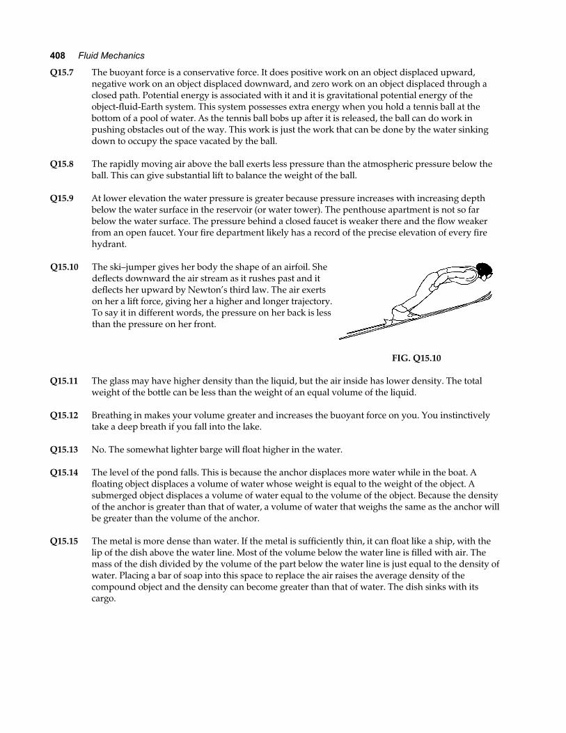
Q15.10 The ski–jumper gives her body the shape of an airfoil. She
deflects downward the air stream as it rushes past and it deflects her upward by Newton’s third law. The air exerts on her a lift force, giving her a higher and longer trajectory. To say it in different words, the pressure on her back is less than the pressure on her front.
FIG. Q15.10
Q15.11 The glass may have higher density than the liquid, but the air inside has lower density. The total
weight of the bottle can be less than the weight of an equal volume of the liquid. Q15.12 Breathing in makes your volume greater and increases the buoyant force on you. You instinctively
take a deep breath if you fall into the lake. Q15.13 No. The somewhat lighter barge will float higher in the water. Q15.14 The level of the pond falls. This is because the anchor displaces more water while in the boat. A
floating object displaces a volume of water whose weight is equal to the weight of the object. A submerged object displaces a volume of water equal to the volume of the object. Because the density of the anchor is greater than that of water, a volume of water that weighs the same as the anchor will be greater than the volume of the anchor.
Q15.15 The metal is more dense than water. If the metal is sufficiently thin, it can float like a ship, with the
lip of the dish above the water line. Most of the volume below the water line is filled with air. The mass of the dish divided by the volume of the part below the water line is just equal to the density of water. Placing a bar of soap into this space to replace the air raises the average density of the compound object and the density can become greater than that of water. The dish sinks with its cargo.
Chapter 15 409
Q15.16 The excess pressure is transmitted undiminished throughout the container. It will compress air inside the wood. The water driven into the wood raises its average density and makes if float lower in the water. Add some thumbtacks to reach neutral buoyancy and you can make the wood sink or rise at will by subtly squeezing a large clear–plastic soft–drink bottle. Bored with graph paper and proving his own existence, René Descartes invented this toy or trick.
Q15.17 The air in your lungs, the blood in your arteries and veins, and the protoplasm in each cell exert
nearly the same pressure, so that the wall of your chest can be in equilibrium. Q15.18 We suppose the compound object floats. In both orientations it displaces its own weight of water, so
it displaces equal volumes of water. The water level in the tub will be unchanged when the object is turned over. Now the steel is underwater and the water exerts on the steel a buoyant force that was not present when the steel was on top surrounded by air. Thus, slightly less wood will be below the water line on the block. It will appear to float higher.
Q15.19 Regular cola contains a considerable mass of dissolved sugar. Its density is higher than that of water.
Diet cola contains a very small mass of artificial sweetener and has nearly the same density as water. The low–density air in the can has a bigger effect than the thin aluminum shell, so the can of diet cola floats.
Q15.20 The air at the lower hole is in the stagnant layer next to the ground and has nearly zero velocity. The
mound entrance is high enough to be in a layer of moving air. A breeze from any direction speeds up to go over the mound and the air pressure drops. Air then flows through the burrow from the lower entrance to the upper entrance.
Q15.21 Clap your shoe or wallet over the hole, or a seat cushion, or your hand. Anything that can sustain a
force on the order of 100 N is strong enough to cover the hole and greatly slow down the escape of the cabin air. You need not worry about the air rushing out instantly, or about your body being “sucked” through the hole, or about your blood boiling or your body exploding. If the cabin pressure drops a lot, your ears will pop and the saliva in your mouth may boil—at body temperature—but you will still have a couple of minutes to plug the hole and put on your emergency oxygen mask. Passengers who have been drinking carbonated beverages may find that the carbon dioxide suddenly comes out of solution in their stomachs, distending their vests, making them belch, and all but frothing from their ears; so you might warn them of this effect.
Q15.22 (a) The fluid around the compass needle exerts kinetic friction to take energy out of its
oscillation. As the needle’s speed approaches zero the friction force goes precisely to zero, so it cannot throw off the final direction of the stationary needle.
(b) When the level is set in a new orientation, the air bubble will move toward a new
equilibrium position in the tube. It will tend to oscillate around this position, but fluid friction quickly degrades its energy of oscillation into internal energy. Exerting zero static friction, the water cannot throw off the final position of the bubble. To calibrate a newly constructed level, set it on a known level surface, wait a moment, and scribe two lines on the outer surface of the transparent tube bracketing the ends of the bubble.
(c) The soap will come to rest at the drain. Kinetic friction takes away its kinetic energy. With
no static friction, the soap can stand in equilibrium only at the lowest point of the bathtub. Try it! Compare its motion with that of a dense spherical ball released in the tub.
410 Fluid Mechanics
SOLUTIONS TO PROBLEMS Section 15.1 Pressure
P15.1 M V= = LNM
OQPρ πiron
3 kg m m7 86043
0 015 0 3e j b g.
M = 0 111. kg
P15.2 Let Fg be its weight. Then each tire supports Fg
4,
so PFA
F
Ag= =
4
yielding F APg = = × = ×4 4 0 024 0 200 10 1 92 103 4. . m N m N2 2e je j
P15.3 PFA
= =×
= ×−
50 0 9 80
0 500 106 24 10
2 26. .
..
a fe jπ
N m2
P15.4 The Earth’s surface area is 4 2πR . The force pushing inward over this area amounts to
F P A P R= =0 024πe j .
This force is the weight of the air:
F mg P Rg = = 024πe j
so the mass of the air is
mP R
g= =
× ×LNM
OQP = ×
02 5 6 2
184 1 013 10 4 6 37 10
9 805 27 10
π πe j e j e j. .
..
N m m
m s kg
2
2 .
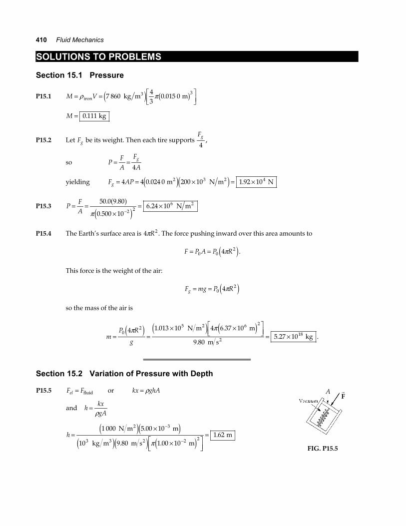
Section 15.2 Variation of Pressure with Depth P15.5 F Fel = fluid or kx ghA= ρ
and hkxgA
=ρ
h =×
×LNM
OQP
=−
−
1 000 5 00 10
10 9 80 1 00 101 62
3
3 2 2
N m m
kg m m s m m
2
3 2
e je je je j e j
.
. ..
π
rF
A
FIG. P15.5
Chapter 15 411
P15.6 (a) P P gh= + = × +051 013 10 1 024 9 80 1 000ρ . . Pa kg m m s m3 2e je jb g
P = ×1 01 107. Pa
(b) The gauge pressure is the difference in pressure between the water outside and the air
inside the submarine, which we suppose is at 1.00 atmosphere.
P P P ghgauge Pa= − = = ×071 00 10ρ .
The resultant inward force on the porthole is then
F P A= = × = ×gauge Pa m N1 00 10 0 150 7 09 107 2 5. . .πa f .
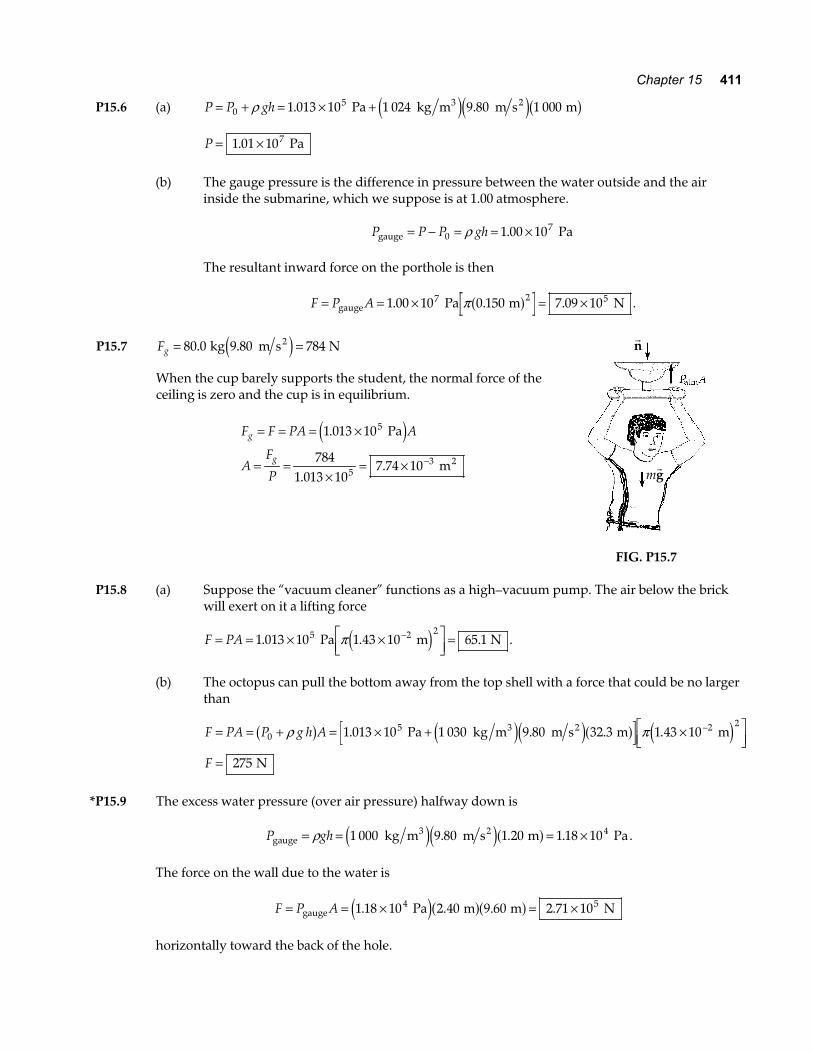
P15.7 Fg = =80 0 9 80 784. . kg m s N2e j
When the cup barely supports the student, the normal force of the ceiling is zero and the cup is in equilibrium.
F F PA A
AF
P
g
g
= = = ×
= =×
= × −
1 013 10
7841 013 10
7 74 10
5
53
.
..
Pa
m2
e j
rn
mrg
FIG. P15.7 P15.8 (a) Suppose the “vacuum cleaner” functions as a high–vacuum pump. The air below the brick
will exert on it a lifting force
F PA= = × ×LNM
OQP =
−1 013 10 1 43 10 65 15 2 2. . . Pa m Nπe j .
(b) The octopus can pull the bottom away from the top shell with a force that could be no larger
than
F PA P g h A
F
= = + = × + ×LNM
OQP
=
−0
5 2 21 013 10 1 030 9 80 32 3 1 43 10
275
ρ πb g e je ja f e j. . . . Pa kg m m s m m
N
3 2
*P15.9 The excess water pressure (over air pressure) halfway down is
P ghgauge3 2 kg m m s m Pa= = = ×ρ 1 000 9 80 1 20 1 18 104e je ja f. . . .
The force on the wall due to the water is
F P A= = × = ×gauge Pa m m N1 18 10 2 40 9 60 2 71 104 5. . . .e ja fa f
horizontally toward the back of the hole.
412 Fluid Mechanics
P15.10 The pressure on the bottom due to the water is P gzb = = ×ρ 1 96 104. Pa
So, F P Ab b= = ×5 88 106. N
On each end, F PA= = × =9 80 10 20 0 1963. . Pa m kN2e j
On the side, F PA= = × =9 80 10 60 0 5883. . Pa m kN2e j
*P15.11 The fluid in the hydraulic jack is originally exerting the same pressure as the air outside. This
pressure P0 results in zero net force on either piston. For the equilibrium of piston 2 we require
5001 5
0 0
2
lb in.2
= − = − FHG
IKJP P A P Pb g b gπ .
Let F1 represent the force the lever bar exerts on piston 1. Then similarly
F P P1 0
20 25= − FHG
IKJb gπ . in.
2
We ignore the weights of the pistons, sliding friction, and the slight difference in fluid pressure P
due to the height difference between points 1 and 2. By division
F
F
12
1
5000 25
500 lb
in.1.5 in.
lb36
= FHGIKJ
=
.
We say the hydraulic lift has an ideal mechanical advantage of 36. Next for the lever bar we ignore
weight and friction, assume equilibrium, and take torques about the fixed hinge.
τ∑ = 0 F F1 2 12 0 in. in.a f a f− = FF
= 1
6
The lever has an ideal mechanical advantage of 6. By substitution,
F =⋅
=5002 31
lb36 6
lb.
Section 15.3 Pressure Measurements P15.12 (a) We imagine the superhero to produce a perfect vacuum in the straw. Take point 1 at the
water surface in the basin and point 2 at the water surface in the straw:
P gy P gy1 1 2 2+ = +ρ ρ
1 013 10 0 0 1 000 9 8052. .× + = + N m kg m m s2 3 2e je jy y2 10 3= . m
(b) No atmosphere can lift the water in the straw through zero height difference.
Chapter 15 413
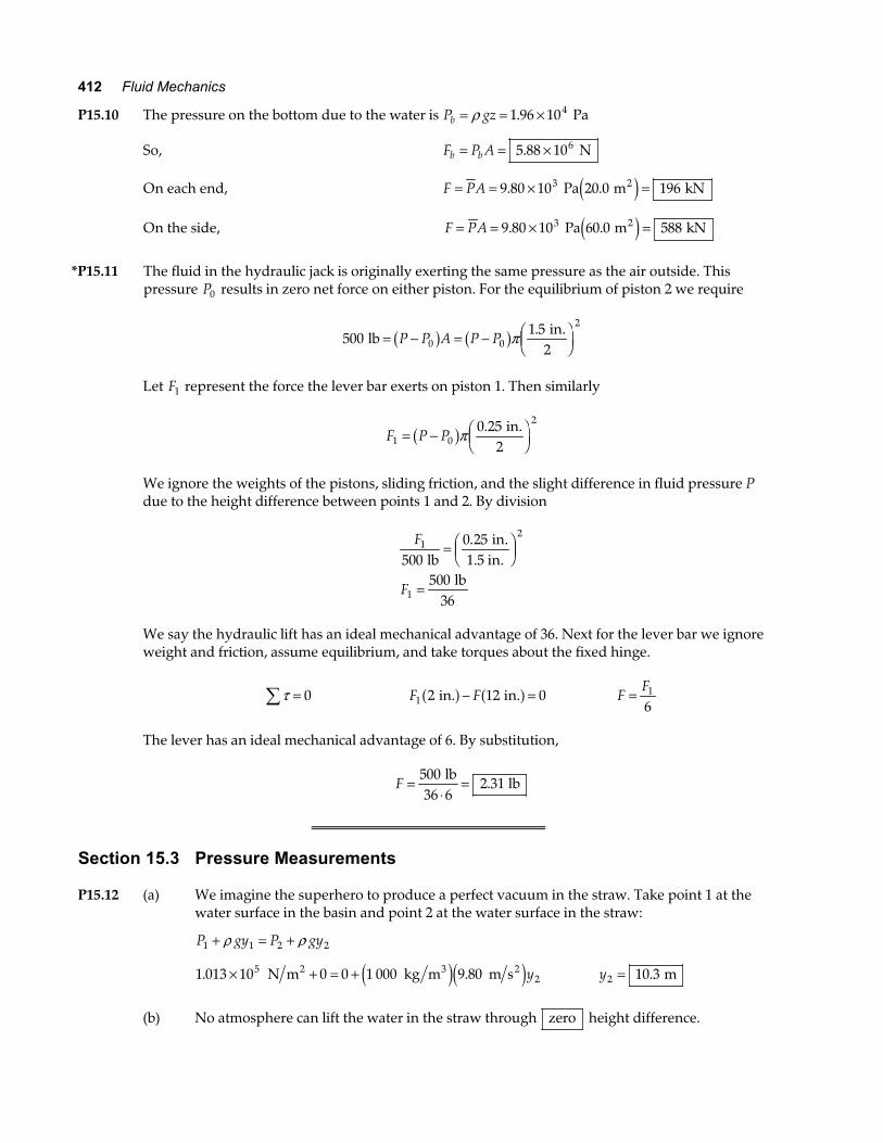
P15.13 P gh0 = ρ
hP
g= = ×
×=0
51 013 10
9 8010 5
ρ.
..
Pa
0.984 10 kg m m s m
3 3 2e je j
No. Some alcohol and water will evaporate. The equilibrium
vapor pressures of alcohol and water are higher than the vapor pressure of mercury.
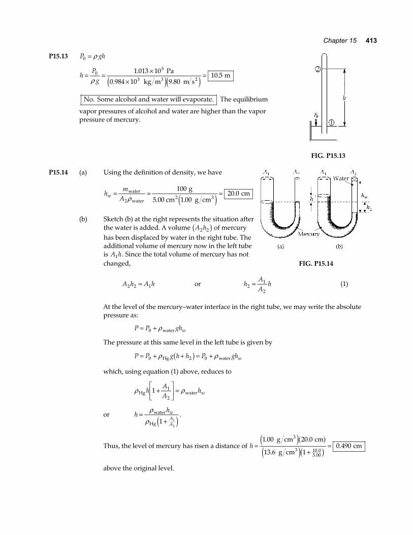
FIG. P15.13 P15.14 (a) Using the definition of density, we have
hm
Aw = = =water
water2 3
g
5.00 cm g cm cm
2
100
1 0020 0
ρ ..
e j (b) Sketch (b) at the right represents the situation after
the water is added. A volume A h2 2b g of mercury has been displaced by water in the right tube. The additional volume of mercury now in the left tube is A h1 . Since the total volume of mercury has not changed,
FIG. P15.14
A h A h2 2 1= or hAA
h21
2= (1)
At the level of the mercury–water interface in the right tube, we may write the absolute
pressure as:
P P ghw= +0 ρ water
The pressure at this same level in the left tube is given by
P P g h h P ghw= + + = +0 2 0ρ ρHg waterb g
which, using equation (1) above, reduces to
ρ ρHg waterhAA
hw1 1
2+LNM
OQP
=
or hhw
AA
=+
ρρ
water
Hg 1 1
2e j
.
Thus, the level of mercury has risen a distance of h =+
=1 00 20 0
13 6 10 490
10 05 00
. .
..
..
g cm cm
g cm cm
3
3
e ja fe jc h
above the original level.
414 Fluid Mechanics
P15.15 ∆ ∆P g h032 66 10= = − ×ρ . Pa : P P P= + = − × = ×0 0
5 51 013 0 026 6 10 0 986 10∆ . . .b g Pa Pa
P15.16 (a) P P gh= +0 ρ
The gauge pressure is
P P gh− = = = = ×
×FHG
IKJ
=
031 000 0 160 1 57 1 57 10
1
0 015 5
ρ kg 9.8 m s m kPa Pa atm
1.013 10 Pa
atm
25e ja f. . .
. .
It would lift a mercury column to height
hP P
g=
−= =0 1 568
9 811 8
ρPa
13 600 kg m m s mm
3 2e je j.. .
(b) Increased pressure of the cerebrospinal fluid will raise the level of the fluid in the
spinal tap.
(c) Blockage of the fluid within the spinal column or between the skull and the spinal
column would prevent the fluid level from rising.
*P15.17 (a) The volume of the tube is
π π
ρ
r
m V
2 2 4
4
0 010 5 1 6 5 54 10
13 6 5 54 10 7 54
l = = ×
= = × × =
−
−
. . .
. . .
m m m
10 kg m m kg
3
3 3 3
b g a fe je j
(b) We suppose that no air bubbles into the tube. The vacuum above the mercury column exerts
no force on the plastic. The mercury column exerts no vertical force on the tube. Since the tube has thin walls, we ignore any buoyant force exerted on the tube by the mercury in the pan. The forces on the tube are the cord tension T upward; its weight
Fg = =0 480 9 8 4 70. . . kg m s N2b ge j downward; and a force exerted downward on its top end
by the air above.
F PA= = × =1 013 10 0 010 6 35 15 2. . . N m m N2e j b gπ
Now F may y∑ = , + − − =T 4 70 35 1 0. .N N , T = 39 8. N .
(c) The table supports the weight of all of the mercury and the pan. The surrounding air exerts
equal upward and downward forces on most of the footprint area of the mercury, but there is no air above the mercury column. The air vertically below the column exerts an upward force on the pan equal to 35.1 N as computed above. For the equilibrium of the mercury and pan,
+ − − + =
= − =
n
n
7 54 9 8 0 32 9 8 35 1 0
77 0 35 1 41 9
. . . . .
. . .
kg m s kg m s N
N N N
2 2b ge j b ge j
continued on next page
Chapter 15 415
(d) In the “Torricellian vacuum” above the mercury column, a barometer reads zero .
(e) The leak slowly raises the air pressure above the mercury column. The height of this column
above the mercury in the pan decreases, but this change has no effect on T or n. The air in the space above the mercury column pushes up on the top of the tube to decrease T. It pushes down on the mercury column to increase n.
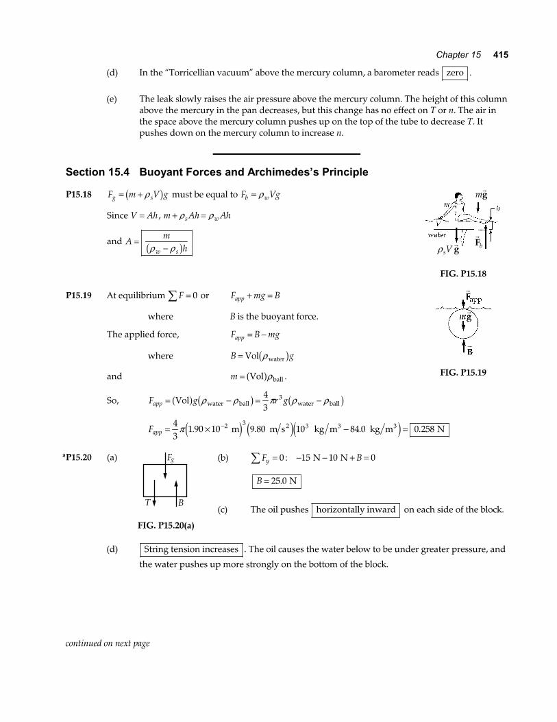
Section 15.4 Buoyant Forces and Archimedes’s Principle P15.18 F m V gg s= + ρb g must be equal to F Vgb w= ρ
Since V Ah= , m Ah Ahs w+ =ρ ρ
and Am
hw s=
−ρ ρb g
mrg
rFbρ sV
rg
FIG. P15.18
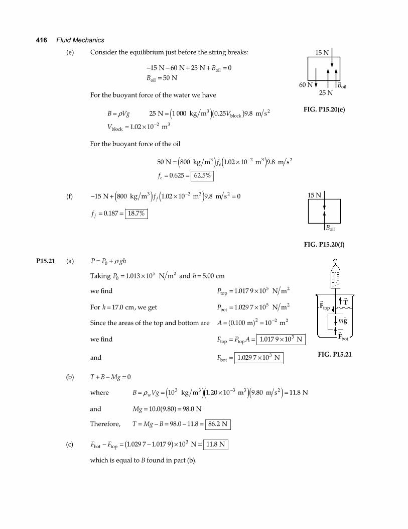
P15.19 At equilibrium F∑ = 0 or F mg Bapp + =
where B is the buoyant force.
The applied force, F B mgapp = −
where B g= Vol waterρb g
and m = Vol balla fρ .
So, F g r gapp = − = −Vol water ball water balla f b g b gρ ρ π ρ ρ43
3
r
r
r
FIG. P15.19
Fapp = × − =−43
1 90 10 9 80 10 84 0 0 2582 3 3π . . . . m m s kg m kg m N2 3 3e j e je j
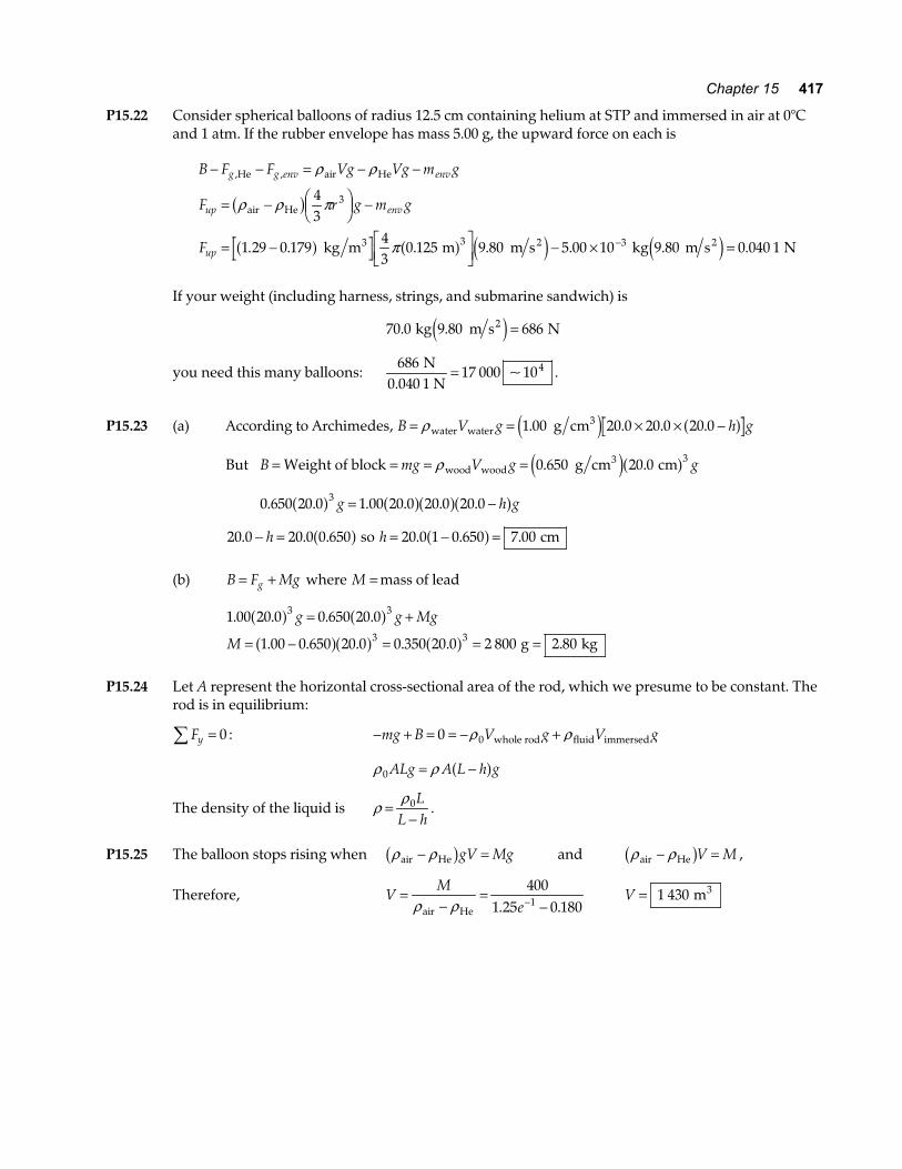
*P15.20 (a) Fg
T B
FIG. P15.20(a)
(b) Fy∑ = 0 : − − + =15 10 0N N B
B = 25 0. N
(c) The oil pushes horizontally inward on each side of the block.
(d) String tension increases . The oil causes the water below to be under greater pressure, and
the water pushes up more strongly on the bottom of the block.
continued on next page
416 Fluid Mechanics
(e) Consider the equilibrium just before the string breaks:
− − + =
=15 60 25 0
50 N N N+
Noil
oil
BB
For the buoyant force of the water we have
B Vg V
V
= =
= × −
ρ 25 1 000 0 25 9 8
1 02 10 2
N kg m m s
m
3block
2
block3
e jb g. .
.
60 N B25 N
15 N
oil
FIG. P15.20(e)
For the buoyant force of the oil
50 800 1 02 10 9 8
0 625 62 5%
2 N kg m m m s3 3 2= ×
= =
−e j e jf
f
e
e
. .
. .
(f) − + × =−15 800 1 02 10 9 8 02 N kg m m m s3 3 2e j e jf f . .
f f = =0 187 18 7%. .
B
15 N
oil
FIG. P15.20(f) P15.21 (a) P P gh= +0 ρ
Taking P051 013 10= ×. N m2 and h = 5 00. cm
we find Ptop2 N m= ×1 017 9 105.
For h = 17 0. cm, we get Pbot2 N m= ×1 029 7 105.
Since the areas of the top and bottom are A = = −0 100 102 2. m m2a f
we find F P Atop top N= = ×1 017 9 103.
and Fbot N= ×1 029 7 103.
rT
rFbot
rFtop
mrg
FIG. P15.21
(b) T B Mg+ − = 0
where B Vgw= = × =−ρ 10 1 20 10 9 80 11 83 3 kg m m m s N3 3 2e je je j. . .
and Mg = =10 0 9 80 98 0. . .a f N
Therefore, T Mg B= − = − =98 0 11 8 86 2. . . N
(c) F Fbot top N N− = − × =1 029 7 1 017 9 10 11 83. . .b g
which is equal to B found in part (b).
Chapter 15 417
P15.22 Consider spherical balloons of radius 12.5 cm containing helium at STP and immersed in air at 0°C and 1 atm. If the rubber envelope has mass 5.00 g, the upward force on each is
B F F Vg Vg m g
F r g m g
F
g g env env
up env
up
− − = − −
= − FHGIKJ −
= − LNM
OQP − × =−
, ,
. . . . . .
He air He
air He
3 2 2 kg m m m s kg 9.80 m s N
ρ ρ
ρ ρ π
π
b g
a f a f e j e j
43
1 29 0 17943
0 125 9 80 5 00 10 0 040 1
3
3 3
If your weight (including harness, strings, and submarine sandwich) is
70 0 9 80 686. . kg m s N2e j =
you need this many balloons: 686
17 000 104N0.040 1 N
= ~ .
P15.23 (a) According to Archimedes, B V g h g= = × × −ρ water water
3 g cm1 00 20 0 20 0 20 0. . . .e j a f
But B mg V g g= = = =Weight of block g cm cmwood wood3ρ 0 650 20 0 3. .e ja f
0 650 20 0 1 00 20 0 20 0 20 03. . . . . .a f a fa fa fg h g= −
20 0 20 0 0 650. . .− =h a f so h = − =20 0 1 0 650 7 00. . .a f cm
(b) B F Mgg= + where M = mass of lead
1 00 20 0 0 650 20 0
1 00 0 650 20 0 0 350 20 0 2 800 2 80
3 3
3 3
. . . .
. . . . . .
a f a fa fa f a f
g g Mg
M
= +
= − = = = g kg
P15.24 Let A represent the horizontal cross-sectional area of the rod, which we presume to be constant. The
rod is in equilibrium:
Fy∑ = 0 : − + = = − +mg B V g V g0 0ρ ρwhole rod fluid immersed
ρ ρ0 ALg A L h g= −a f
The density of the liquid is ρ ρ=
−0L
L h.
P15.25 The balloon stops rising when ρ ρair He− =b ggV Mg and ρ ρair He− =b gV M ,
Therefore, VM
e=
−=
−−ρ ρair He
4001 25 0 1801. .
V = 1 430 m3
418 Fluid Mechanics
P15.26 Constant velocity implies zero acceleration, which means that the submersible is in equilibrium under the gravitational force, the upward buoyant force, and the upward resistance force:
F may y∑ = = 0 − × + + + =1 20 10 1 100 04. kg Nm g gVwe j ρ
where m is the mass of the added water and V is the sphere’s volume.
1 20 10 1 03 1043
1 501 1004 3 3. . .× + = × L
NMOQP + kg
N9.8 m s2m πa f
so m = ×2 67 103. kg
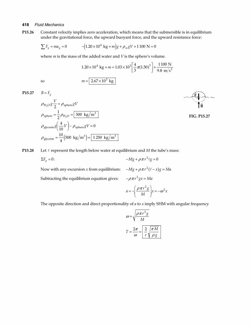
P15.27 B Fg=
ρ ρ
ρ ρ
ρ ρ
ρ
H O sphere
sphere H O3
glycerin sphere
glycerin3 3
2
2 kg m
kg m kg m
gV
gV
g V gV
212
500
410
0
104
500 1 250
=
= =
FHGIKJ − =
= =e j
rB
rFg
FIG. P15.27
P15.28 Let l represent the length below water at equilibrium and M the tube’s mass:
Σ =Fy 0: − + =Mg r gρπ 2 0l
Now with any excursion x from equilibrium: − + − =Mg r x g Maρπ 2 la f
Subtracting the equilibrium equation gives: − =ρπ r gx Ma2
ar g
Mx x= −
FHG
IKJ = −
ρπ ω2
2
The opposite direction and direct proportionality of a to x imply SHM with angular frequency
ωρπ
=r g
M
2
Tr
Mg
= =2 2πω
πρ
Chapter 15 419
*P15.29 The water exerts a buoyant force on the air, given by
B gV= =FHGIKJ =ρ fluid
3 23
kg m m s L m
L N1 000 9 8 10
110
983e je ja f. up
The weight of the air is
F gVg = = × =−ρ 2 4 9 8 10 10 0 2353. . . kg m m s m N3 2 3e je je j down
To transport the air down at constant speed requires a downward force D in + − − =98 0 235 0 N N. D ,
D = 97 8. N , and work W = ⋅ = ° =r rD d 97 8 10 3 0 1 01. . cos . N m kJa fa f .
Section 15.5 Fluid Dynamics Section 15.6 Streamlines and the Continuity Equation for Fluids Section 15.7 Bernoulli’s Equation P15.30 Volume flow rate = =A v A v1 1 2 2
20 060 0
1 0001 00 0 5002 2.
.. .
L s
cm1 L
cm cm3
hose nozzleFHG
IKJ = =π πa f a fv v
(a) vhose
3
2
cm s cm
cm s= =3333 14
106.
(b) vnozzle
3
2
cm s cm
cm s= =3330 785
424.
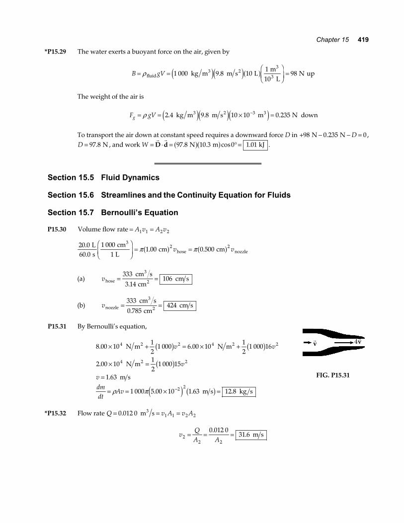
P15.31 By Bernoulli’s equation,
8 00 1012
1 000 6 00 1012
1 000 16
2 00 1012
1 000 15
1 63
1 000 5 00 10 1 63 12 8
4 2 4 2
4 2
2 2
. .
.
.
. . .
× + = × +
× =
=
= = × =−
N m N m
N m
m s
m s kg s
2 2
2
b g b g
b g
e j b g
v v
v
vdmdt
Avρ π
rv 4
rv
FIG. P15.31
*P15.32 Flow rate Q v A v A= = =0 012 0 1 1 2 2. m s3
vQA A2
2 2
0 012 031 6= = =
.. m s
420 Fluid Mechanics
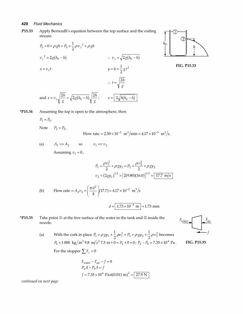
P15.33 Apply Bernoulli’s equation between the top surface and the exiting stream.
P gh P v ghx0 020
12
+ + = + +ρ ρ ρ
v g h hx2
02= −b g ∴ = − v g h hx 2 0b g
x v tx= : y h g t= = 12
2
∴ = th
g2
and x vh
gg h h
hgx= = −2
22
0b g : x h h h= −2 0b g
FIG. P15.33
*P15.34 Assuming the top is open to the atmosphere, then
P P1 0= .
Note P P2 0= . Flow rate = × = ×− −2 50 10 4 17 103 5. min . m m s3 3 .
(a) A A1 2>> so v v1 2<<
Assuming v1 0= ,
P
vgy P
vgy
v gy
112
1 222
2
2 11 2 1 2
2 2
2 2 9 80 16 0 17 7
+ + = + +
= = =
ρρ
ρρ
b g a fa f. . . m s
(b) Flow rate = =FHGIKJ = × −A v
d2 2
25
417 7 4 17 10
π. .a f m s3
d = × =−1 73 10 1 733. . m mm
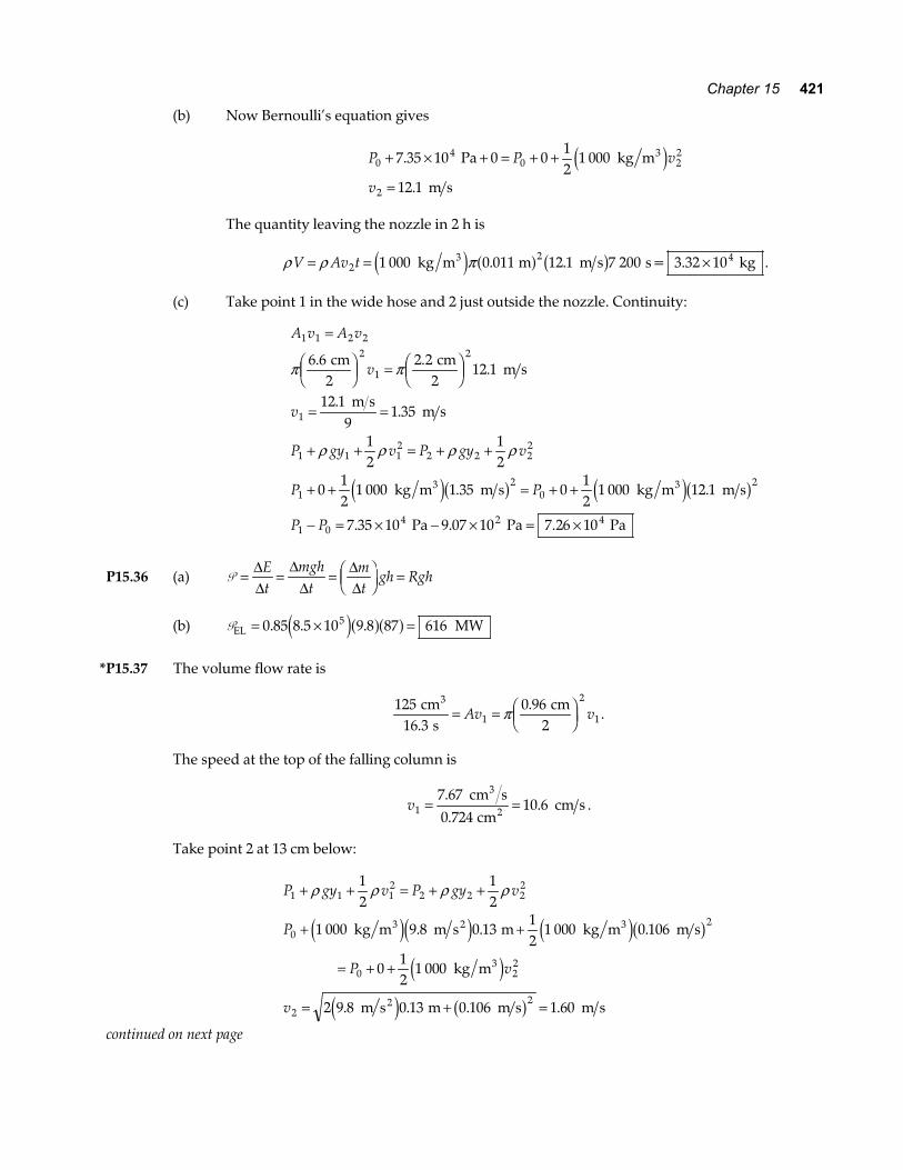
*P15.35 Take point 1 at the free surface of the water in the tank and 2 inside the
nozzle.
(a) With the cork in place P gy v P gy v1 1 12
2 2 221
212
+ + = + +ρ ρ ρ ρ becomes
P P0 21 000 9 8 7 5 0 0 0+ + = + + kg m m s m3 2. . ; P P2 047 35 10− = ×. Pa .
For the stopper Fx∑ = 0
F F fP A P A f
f
water air
Pa 0.011 m N
− − =− =
= × =
0
7 35 10 27 9
2 0
4 2. .π a f
Fwater Fair
f
FIG. P15.35
continued on next page
Chapter 15 421
(b) Now Bernoulli’s equation gives
P P v
v
04
0 22
2
7 35 10 0 012
1 000
12 1
+ × + = + +
=
.
.
Pa kg m
m s
3e j
The quantity leaving the nozzle in 2 h is
ρ ρ πV Av t= = ×221 000 0 011 12 1 7 200 kg m m m s s= 3.32 10 kg3 4e j a f b g. . .
(c) Take point 1 in the wide hose and 2 just outside the nozzle. Continuity:
A v A v
v
v
P gy v P gy v
P P
P P
1 1 2 22
1
2
1
1 1 12
2 2 22
12
02
1 04 2 4
6 6 2 212 1
12 19
1 35
12
12
012
1 000 1 35 012
1 000 12 1
7 35 10 9 07 10 7 26 10
=
FHG
IKJ = FHG
IKJ
= =
+ + = + +
+ + = + +
− = × − × = ×
π π
ρ ρ ρ ρ
. ..
..
. .
. . .
cm2
cm2
m s
m s m s
kg m m s kg m m s
Pa Pa Pa
3 3e jb g e jb g
P15.36 (a) P = = = FHGIKJ =∆
∆∆
∆∆∆
Et
mght
mt
gh Rgh
(b) PEL MW= × =0 85 8 5 10 9 8 87 6165. . .e ja fa f
*P15.37 The volume flow rate is
125
16 30 96
1
2
1 cm
s cm
2
3
..= = FHGIKJAv vπ .
The speed at the top of the falling column is
v17 670 724
10 6= =..
. cm s
cm cm s
3
2 .
Take point 2 at 13 cm below:
P gy v P gy v
P
P v
v
1 1 12
2 2 22
02
0 22
22
12
12
1 000 9 8 0 1312
1 000 0 106
012
1 000
2 9 8 0 13 0 106 1 60
+ + = + +
+ +
= + +
= + =
ρ ρ ρ ρ
kg m m s m kg m m s
kg m
m s m m s m s
3 2 3
3
2
e je j e jb g
e j
e j b g
. . .
. . . .
continued on next page
422 Fluid Mechanics
The volume flow rate is constant:
7 67
2160
0 247
2
.
.
cm s cm s
cm
3 = FHGIKJ
=
π d
d
P15.38 (a) Between sea surface and clogged hole: P v gy P v gy1 12
1 2 22
212
12
+ + = + +ρ ρ ρ ρ
1 0 1 030 9 8 2 0 02 atm kg m m s m3 2+ + = + +e je ja f. P P2 1 20 2= +atm kPa.
The air on the back of his hand pushes opposite the water, so the net force on his hand is
F PA= = × FHGIKJ × −20 2 10
41 2 103 2 2
. . N m m2e j e jπ F = 2 28. N
(b) Now, Bernoulli’s theorem is
1 0 20 2 112
1 030 022 atm kPa atm kg m3+ + = + +. e jv v2 6 26= . m s
The volume rate of flow is A v2 22 2 4
41 2 10 6 26 7 08 10= × = ×− −π. . . m m s m s3e j b g
One acre–foot is 4 047 0 304 8 1 234 m m m2 3× =.
Requiring 1 234
7 08 101 74 10 20 24
6 m m s
s days3
3.. .
×= × =−
P15.39 (a) Suppose the flow is very slow: P v gy P v gy+ +FHG
IKJ = + +FHG
IKJ
12
12
2 2ρ ρ ρ ρriver rim
P g g
P
+ + = + +
= + = +
0 564 1 0 2 096
1 1 000 9 8 1 532 1 15 0
ρ ρ m atm m
atm kg m m s m atm MPa3 2
a f b ge je jb g. .
(b) The volume flow rate is 4 5004
2
m d3 = =Avd vπ
v = FHG
IKJFHG
IKJ
=4 5001 4
0 1502 952 m d
d86 400 s m
m s3e j a fπ ..
(c) Imagine the pressure as applied to stationary water at the bottom of the pipe:
P v gy P v gy
P
P
+ +FHG
IKJ = + +F
HGIKJ
+ = + +
= + +
12
12
0 112
1 000 2 95 1 000 1 532
1 15 0 4 34
2 2
2
ρ ρ ρ ρbottom top
3 2 atm kg m m s kg 9.8 m s m
atm MPa kPa
e jb g e jb g.
. .
The additional pressure is 4 34. kPa .
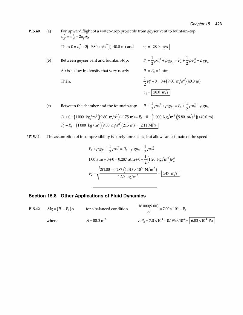
Chapter 15 423
P15.40 (a) For upward flight of a water-drop projectile from geyser vent to fountain–top, v v a yyf yi y
2 2 2= + ∆
Then 0 2 9 80 40 02= + − +vi . . m s m2e ja f and vi = 28 0. m s
(b) Between geyser vent and fountain-top: P v gy P v gy1 12
1 2 22
212
12
+ + = + +ρ ρ ρ ρ
Air is so low in density that very nearly P P1 2 1= = atm
Then, 12
0 0 9 80 40 02vi + = + . . m s m2e ja f
v1 28 0= . m s
(c) Between the chamber and the fountain-top: P v gy P v gy1 12
1 2 22
212
12
+ + = + +ρ ρ ρ ρ
P P
P P
1 0
1 0
0 1 000 9 80 175 0 1 000 9 80 40 0
1 000 9 80 215 2 11
+ + − = + + +
− = =
kg m m s m kg m m s m
kg m m s m MPa
3 2 3 2
3 2
e je ja f e je ja fe je ja f
. . .
. .
*P15.41 The assumption of incompressibility is surely unrealistic, but allows an estimate of the speed:
P gy v P gy v
v
v
1 1 12
2 2 22
22
2
5
12
12
1 00 0 0 0 287 012
1 20
2 1 00 0 287 1 013 10
1 20347
+ + = + +
+ + = + +
=− ×
=
ρ ρ ρ ρ
. . .
. . .
.
atm atm kg m
N m
kg m m s
3
2
3
e ja fe j
Section 15.8 Other Applications of Fluid Dynamics
P15.42 Mg P P A= −1 2b g for a balanced condition 16 000 9 80
7 00 1042
..
a fA
P= × −
where A = 80 0. m2 ∴ = × − × = ×P24 4 47 0 10 0 196 10 6 80 10. . . Pa
424 Fluid Mechanics
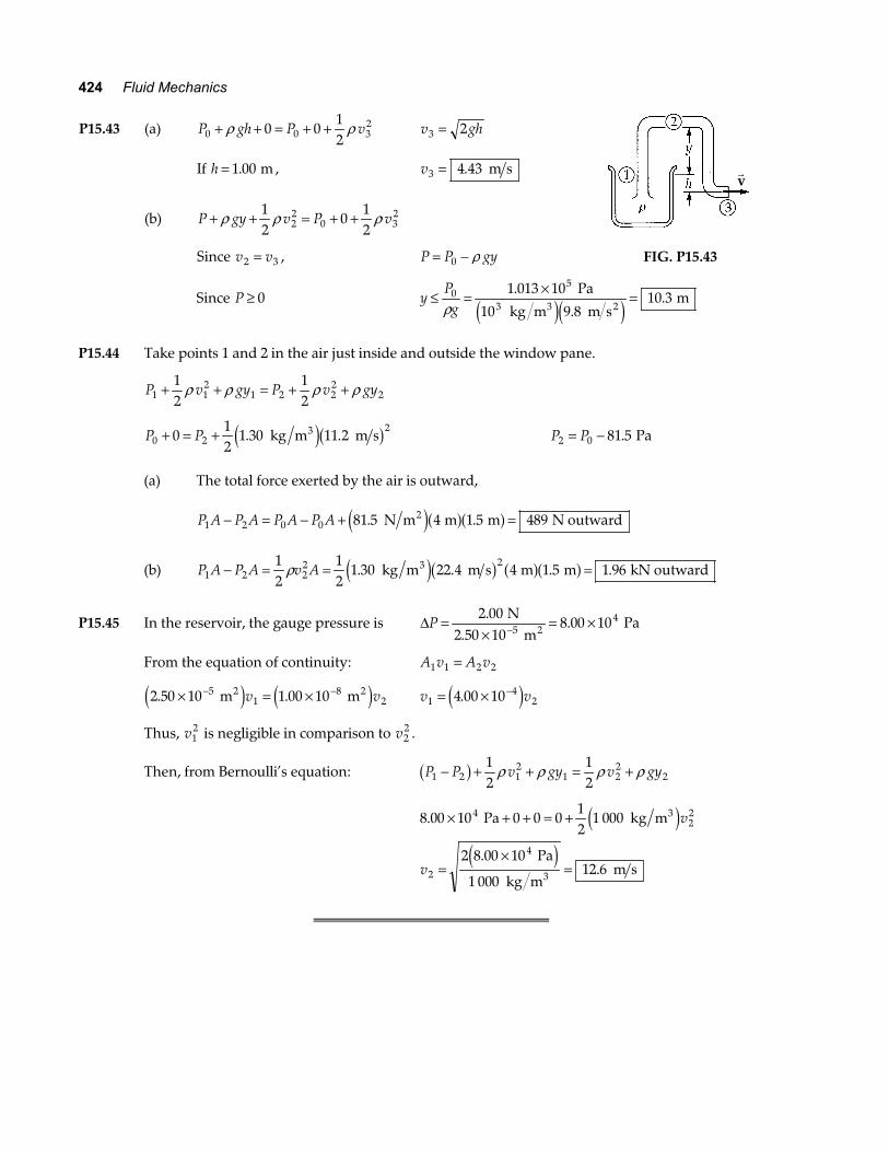
P15.43 (a) P gh P v0 0 320 0
12
+ + = + +ρ ρ v gh3 2=
If h = 1 00. m , v3 4 43= . m s
(b) P gy v P v+ + = + +ρ ρ ρ12
0122
20 3
2
Since v v2 3= , P P gy= −0 ρ
rv
FIG. P15.43
Since P ≥ 0 yPg
≤ = × =051 013 10
9 810 3
ρ.
..
Pa
10 kg m m s m
3 3 2e je j
P15.44 Take points 1 and 2 in the air just inside and outside the window pane.
P v gy P v gy1 12
1 2 22
212
12
+ + = + +ρ ρ ρ ρ
P P0 22
012
1 30 11 2+ = + . . kg m m s3e jb g P P2 0 81 5= − . Pa
(a) The total force exerted by the air is outward, P A P A P A P A1 2 0 0 81 5 4 1 5 489− = − + =. . N m m m N outward2e ja fa f
(b) P A P A v A1 2 22 21
212
1 30 22 4 4 1 5 1 96− = = =ρ . . . . kg m m s m m kN outward3e jb g a fa f
P15.45 In the reservoir, the gauge pressure is ∆P =×
= ×−2 00
8 00 1054.
.N
2.50 10 m Pa2
From the equation of continuity: A v A v1 1 2 2=
2 50 10 1 00 1051
82. .× = ×− − m m2 2e j e jv v v v1
424 00 10= × −.e j
Thus, v12 is negligible in comparison to v2
2 .
Then, from Bernoulli’s equation: P P v gy v gy1 2 12
1 22
212
12
− + + = +b g ρ ρ ρ ρ
8 00 10 0 0 012
1 000
2 8 00 10
1 00012 6
422
2
4
.
..
× + + = +
=×
=
Pa kg m
Pa
kg m m s
3
3
e je j
v
v
Chapter 15 425
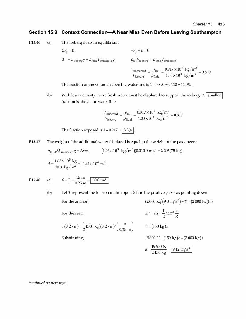
Section 15.9 Context ConnectionA Near Miss Even Before Leaving Southampton P15.46 (a) The iceberg floats in equilibrium
Σ =Fy 0: − + =F Bg 0
0 = − +m g V giceberg fluid immersedρ ρ ρice iceberg fluid immersedV V=
VVimmersed
iceberg
ice
fluid
3
3 kg m
kg m= =
××
=ρ
ρ0 917 101 03 10
0 8903
3..
.
The fraction of the volume above the water line is 1 0 890 0 110 11 0%− = =. . . . (b) With lower density, more fresh water must be displaced to support the iceberg. A smaller
fraction is above the water line
VVimmersed
iceberg
ice
fluid
3
3 kg m
kg m= =
××
=ρ
ρ0 917 101 00 10
0 9173
3..
.
The fraction exposed is 1 0 917 8 3%− =. . .
P15.47 The weight of the additional water displaced is equal to the weight of the passengers:
ρ fluid immersed∆ = ∆V g mg 1 03 10 0 010 0 2 205 753. .× = kg m m kg3e jb g b gA
A =×
= ×1 65 1010 3
1 61 105
4..
. kg
kg m m2
2
P15.48 (a) θ = = =sr
1560 0
m0.25 m
rad.
(b) Let T represent the tension in the rope. Define the positive y axis as pointing down.
For the anchor: 2 000 2 000 kg 9.8 m s kg2b ge j b ga f− =T a
For the reel: Σ = =τ αI MRaR
12
2
Ta
0 2512
300 0 250 25
2. ..
m kg m m
a f b ga f= FHG
IKJ T a= 150 kgb g
Substituting, 19 600 150 2 000 N kg kg− =b g b ga a
a = =19 6002 150
9 12N
kg m s2.
continued on next page
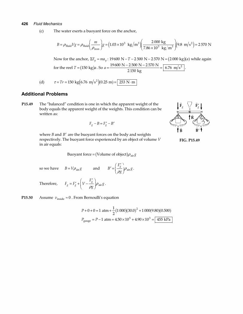
426 Fluid Mechanics
(c) The water exerts a buoyant force on the anchor,
B Vgm
g= =FHGIKJ = ×
×
FHG
IKJ =ρ ρ
ρfluid fluidiron
33
2 kg m kg kg m
m s N1 03 102 000
7 86 109 8 2 5703
3..
.e j e j
Now for the anchor, Σ =F may y : 19 600 2 500 2 570 2 000 N N N kg− − − =T ab ga f while again
for the reel T a= 150 kgb g . So a =− −
=19 600 2 500 2 570
2 1506 76
N N N kg
m s2. .
(d) τ = = = ⋅Tr 150 0 25 253 kg 6.76 m s m N m2e ja f.
Additional Problems P15.49 The “balanced” condition is one in which the apparent weight of the
body equals the apparent weight of the weights. This condition can be written as:
F B F Bg g− = ′ − ′
where B and ′B are the buoyant forces on the body and weights
respectively. The buoyant force experienced by an object of volume V in air equals:
Buoyant force Volume of object air= b gρ g
rB
r′B
rR
rFg
r′Fg
FIG. P15.49
so we have B V g= ρair and ′ =′FHGIKJB
F
ggg
ρρair .
Therefore, F F VF
ggg g
g= ′ + −′F
HGIKJρ
ρair .
P15.50 Assume vinside ≈ 0 . From Bernoulli’s equation
P
P P
+ + = + +
= − = × + × =
0 0 112
1 000 30 0 1 000 9 80 0 500
1 4 50 10 4 90 10 455
2
5 3
atm
atm kPagauge
b ga f a fa f. . .
. .
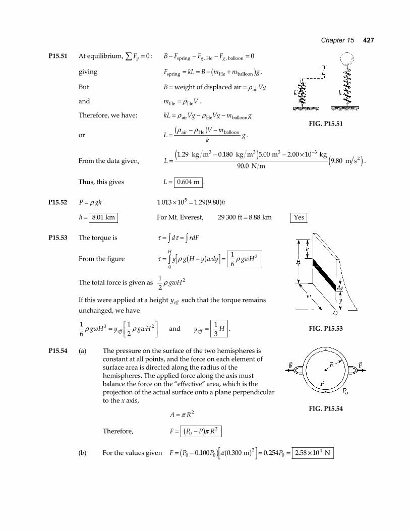
Chapter 15 427
P15.51 At equilibrium, Fy∑ = 0 : B F F Fg g− − − =spring He balloon, , 0
giving F kL B m m gspring He balloon= = − +b g .
But B Vg= =weight of displaced air airρ
and m VHe He= ρ .
Therefore, we have: kL Vg Vg m g= − −ρ ρair He balloon
or LV mk
g=− −ρ ρair He balloonb g
.
FIG. P15.51
From the data given, L =− − × −1 29 0 180 5 00 2 00 10
9 803. . . .
. kg m kg m m kg
90.0 N m m s
3 3 32e j e j .
Thus, this gives L = 0 604. m .
P15.52 P gh= ρ 1 013 10 1 29 9 805. . .× = a fh
h = 8 01. km For Mt. Everest, 29 300 8 88ft km= . Yes
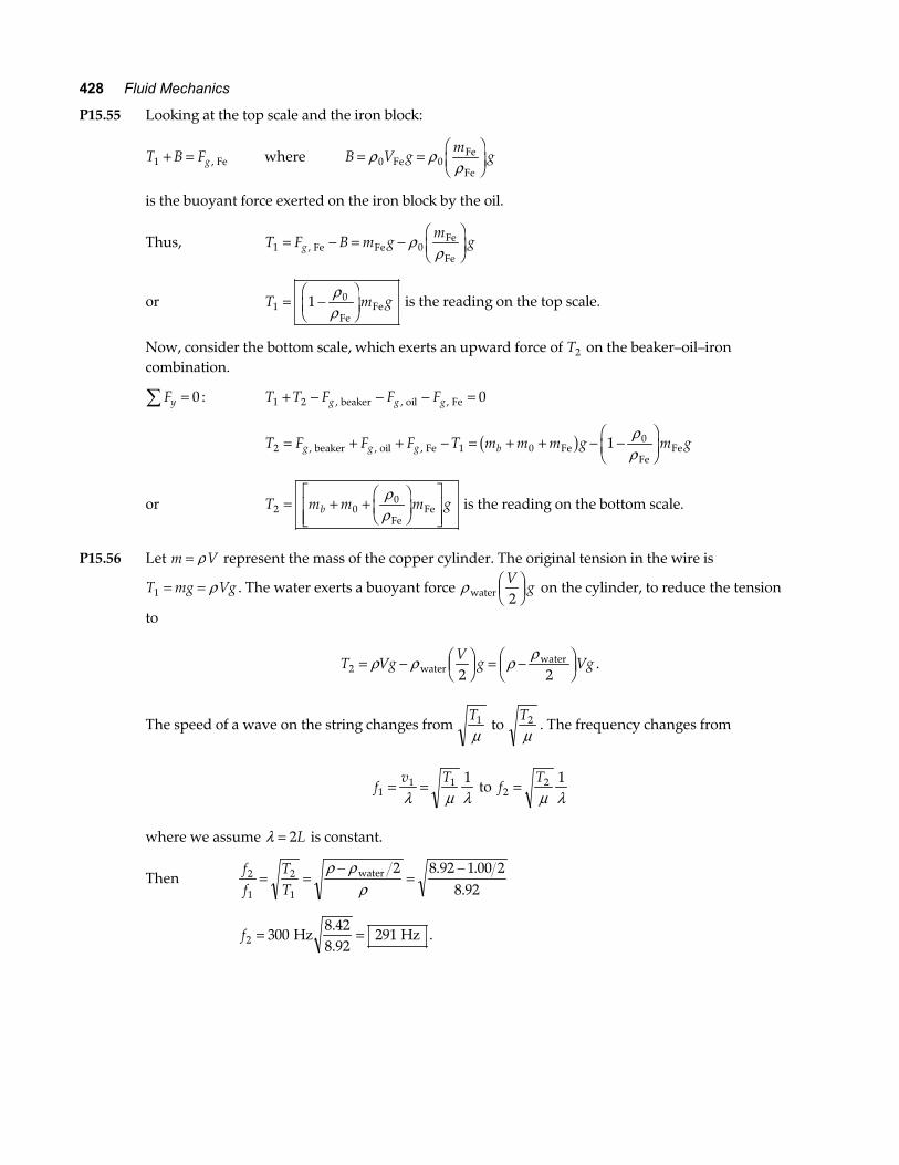
P15.53 The torque is τ τ= =z zd rdF
From the figure τ ρ ρ= − =z y g H y wdy gwHH
b g0
316
The total force is given as 12
2ρ gwH
If this were applied at a height yeff such that the torque remains
unchanged, we have
16
12
3 2ρ ρgwH y gwHeff= LNM
OQP and y Heff = 1
3.
FIG. P15.53
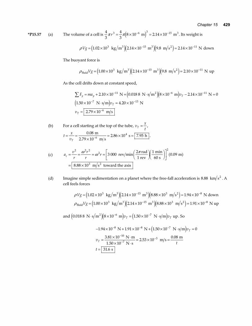
P15.54 (a) The pressure on the surface of the two hemispheres is
constant at all points, and the force on each element of surface area is directed along the radius of the hemispheres. The applied force along the axis must balance the force on the “effective” area, which is the projection of the actual surface onto a plane perpendicular to the x axis,
A R= π 2
Therefore, F P P R= −02b gπ
r r
FIG. P15.54
(b) For the values given F P P P= − = = ×0 02
040 100 0 300 0 254 2 58 10. . . .b g a fπ m N
428 Fluid Mechanics
P15.55 Looking at the top scale and the iron block:
T B Fg1 + = , Fe where B V gm
g= =FHGIKJρ ρ
ρ0 0FeFe
Fe
is the buoyant force exerted on the iron block by the oil.
Thus, T F B m gm
gg1 0= − = −FHGIKJ, Fe Fe
Fe
Feρ
ρ
or T m g101= −
FHG
IKJ
ρρFe
Fe is the reading on the top scale.
Now, consider the bottom scale, which exerts an upward force of T2 on the beaker–oil–iron combination.
Fy∑ = 0 : T T F F Fg g g1 2 0+ − − − =, , , beaker oil Fe
T F F F T m m m g m gg g g b2 1 001= + + − = + + − −
FHG
IKJ, , , beaker oil Fe Fe
FeFeb g ρ
ρ
or T m m m gb2 00= + +FHGIKJ
LNMM
OQPP
ρρFe
Fe is the reading on the bottom scale.
P15.56 Let m V= ρ represent the mass of the copper cylinder. The original tension in the wire is
T mg Vg1 = = ρ . The water exerts a buoyant force ρ waterV
g2FHGIKJ on the cylinder, to reduce the tension
to
T VgV
g Vg2 2 2= − F
HGIKJ = −FHG
IKJρ ρ ρ ρ
waterwater .
The speed of a wave on the string changes from T1
µ to
T2
µ. The frequency changes from
fv T
11 1 1= =
λ µ λ to f
T2
2 1=µ λ
where we assume λ = 2L is constant.
Then ff
TT
2
1
2
1
2 8 92 1 00 28 92
= =−
=−ρ ρ
ρwater . .
.
f2 300 291= = Hz8.428.92
Hz .
Chapter 15 429
*P15.57 (a) The volume of a cell is 43
43
8 10 2 14 103 6 3 15π πr = × = ×− − m m3e j . . Its weight is
ρ Vg = × × = ×− −1 02 10 2 14 10 9 8 2 14 103 15 11. . . . kg m m m s N3 3 2e je je j down
The buoyant force is
ρ fluid3 3 2 kg m m m s NVg = × × = ×− −1 00 10 2 14 10 9 8 2 10 103 15 11. . . .e je je j up
As the cell drifts down at constant speed,
F ma v
v
v
y y T
T
T
∑ = + × + ⋅ × − × =
× ⋅ = ×
= ×
− − −
− −
−
2 10 10 0 018 8 8 10 2 14 10 0
1 50 10 4 20 10
2 79 10
11 6 11
7 13
6
. . .
. .
.
N N s m m N
N s m N
m s
2e je je j
(b) For a cell starting at the top of the tube, vxtT = ,
tx
vT= =
×= × =−
0 082 86 10 7 956
4.. .
m2.79 10 m s
s h .
(c)
avr
rr
rc = = = = FHG
IKJFHGIKJ
LNM
OQP
= ×
2 2 22
2
3
3 0002 1
0 09
8 88 10
ω ω π rev min
rad1 rev
min60 s
m
m s toward the axis2
.
.
a f
(d) Imagine simple sedimentation on a planet where the free-fall acceleration is 8 88. km s2 . A
cell feels forces
ρ
ρ
Vg
Vg
= × × × = ×
= × × × = ×
− −
− −
1 02 10 2 14 10 8 88 10 1 94 10
1 00 10 2 14 10 8 88 10 1 91 10
3 15 3 8
3 15 3 8
. . . .
. . . .
kg m m m s N down
kg m m m s N up
3 3 2
fluid3 3 2
e je je je je je j
and 0 018 8 8 10 1 50 106 7. . N s m m N s m up2⋅ × = × ⋅− −e je j e jv vT T . So
− × + × + × ⋅ =
= × ⋅× ⋅
= × =
=
− − −
−
−−
1 94 10 1 91 10 1 50 10 0
3 81 102 53 10
0 08
31 6
8 8 7
10
73
. . .
..
.
.
N N N s m
N m1.50 10 N s
m s m
s
e jv
vt
t
T
T
430 Fluid Mechanics
P15.58 The incremental version of P P gy− =0 ρ is dP gdy= −ρ
We assume that the density of air is proportional to pressure, or P Pρ ρ
= 0
0
Combining these two equations we have dP PP
gdy= −ρ0
0
dPP
gP
dyP
P h
0
0
0 0z z= −
ρ
and integrating gives lnPP
ghP0
0
0
FHGIKJ = −
ρ
so where α ρ= 0
0
gP
, P P e h= −0
α
P15.59 Energy for the fluid-Earth system is conserved.
K U E K Ui f+ + = +a f a f∆ mech : 02
012
02+ + = +mgL
mv
v gL= = =2 00 4 43. . m 9.8 m s m s2e j
P15.60 Let s stand for the edge of the cube, h for the depth of immersion, ρ ice stand for the density of the
ice, ρ w stand for density of water, and ρ a stand for density of the alcohol. (a) According to Archimedes’s principle, at equilibrium we have
ρ ρ ρρice
icegs ghs h sww
3 2= ⇒ =
With ρ ice3 kg m= ×0 917 103.
ρ w = ×1 00 103. kg m3 and s = 20 0. mm
we get h = = ≈20 0 0 917 18 34 18 3. . . .a f mm mm
(b) We assume that the top of the cube is still above the alcohol surface. Letting ha stand for the
thickness of the alcohol layer, we have
ρ ρ ρa a w wgs h gs h gs2 2 3+ = ice so h s hww
a
wa=
FHGIKJ −FHGIKJ
ρρ
ρρ
ice
continued on next page
Chapter 15 431
With ρ a = ×0 806 103. kg m3 and ha = 5 00. mm
we obtain hw = − = ≈18 34 0 806 5 00 14 31 14 3. . . . .a f mm mm
(c) Here ′ = − ′h s hw a , so Archimedes’s principle gives
ρ ρ ρ ρ ρ ρ
ρ ρρ ρ
a a w a a a w a
aw
w a
gs h gs s h gs h s h s
h s
2 2 3
20 01 000 0 9171 000 0 806
8 557 8 56
′ + − ′ = ⇒ ′ + − ′ =
′ =−−
=−−
= ≈
b g b gb gb g
a fa f
ice ice
ice mm.. .. .
. .
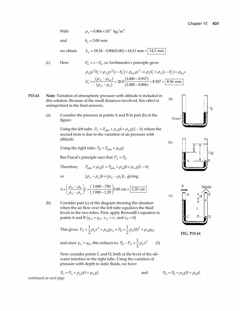
P15.61 Note: Variation of atmospheric pressure with altitude is included in
this solution. Because of the small distances involved, this effect is unimportant in the final answers. (a) Consider the pressure at points A and B in part (b) of the
figure: Using the left tube: P P gh g L hA a w= + + −atm ρ ρ a f where the
second term is due to the variation of air pressure with altitude.
Using the right tube: P P gLB = +atm ρ0 But Pascal’s principle says that P PA B= . Therefore, P gL P gh g L ha watm atm+ = + + −ρ ρ ρ0 a f or ρ ρ ρ ρw a wh L− = −b g b g0 , giving
h Lw
w a=
−−
FHG
IKJ =
−−
FHG
IKJ =
ρ ρρ ρ
0 1 000 7501 000 1 29
5 00 1 25.
. . cm cm
(b) Consider part (c) of the diagram showing the situation
when the air flow over the left tube equalizes the fluid levels in the two tubes. First, apply Bernoulli’s equation to points A and B y y v v vA B A B= = =, , and 0b g
This gives: P v gy P gyA a a A B a a B+ + = + +12
12
02 2ρ ρ ρ ρa f
and since y yA B= , this reduces to: P P vB A a− = 12
2ρ (1)
Now consider points C and D, both at the level of the oil–
water interface in the right tube. Using the variation of pressure with depth in static fluids, we have:
rv
FIG. P15.61
P P gH gLC A a w= + +ρ ρ and P P gH gLD B a= + +ρ ρ0
continued on next page
432 Fluid Mechanics
But Pascal’s principle says that P PC D= . Equating these two gives: P gH gL P gH gLB a A a w+ + = + +ρ ρ ρ ρ0 or P P gLB A w− = −ρ ρ0b g (2)
Substitute equation (1) for P PB A− into (2) to obtain 12
20ρ ρ ρa wv gL= −b g
or vgL w
a=
−=
−FHG
IKJ
22 9 80 0 050 0
1 000 7501 29
0ρ ρρb g e jb g. .
. m s m2
v = 13 8. m s
P15.62 (a) The flow rate, Av, as given may be expressed as follows:
25 0
0 833 833.
.liters
30.0 s liters s cm s3= = .
The area of the faucet tap is π cm2 , so we can find the velocity as
vA
= = = =flow rate cm scm
cm s m s3
2
833265 2 65
π. .
(b) We choose point 1 to be in the entrance pipe and point 2 to be at the faucet tap. A v A v1 1 2 2=
gives v1 0 295= . m s . Bernoulli’s equation is:
P P v v g y y1 2 22
12
2 112
− = − + −ρ ρe j b g and gives
P P1 23 2 2 31
210 2 65 0 295 10 9 80 2 00− = − + kg m m s m s kg m m s m3 3 2e j b g b g e je ja f. . . .
or P P Pgauge Pa= − = ×1 242 31 10. .
P15.63 (a) Since the upward buoyant force is balanced by the weight of the sphere,
m g Vg R g134
3= = FHG
IKJρ ρ π .
In this problem, ρ = 0 789 45. g cm3 at 20.0°C, and R = 1 00. cm so we find:
m R13 34
30 789 45
43
1 00 3 307= FHGIKJ =
LNM
OQP =ρ π π. . . g cm cm g3e j a f .
continued on next page
Chapter 15 433
(b) Following the same procedure as in part (a), with ′ =ρ 0 780 97. g cm3 at 30.0°C, we find:
m R23 34
30 780 97
43
1 00 3 271= ′FHGIKJ =
LNM
OQP =ρ π π. . . g cm cm g3e j a f .
(c) When the first sphere is resting on the bottom of the tube,
n B F m gg+ = =1 1 , where n is the normal force.
Since B Vg= ′ρ
n m g Vg
n
= − ′ = −LNM
OQP
= ⋅ = × −
13
4
3 307 0 780 9743
1 00 980
34 8 3 48 10
ρ π. . .
. .
g g cm cm cm s
g cm s N
3 2
2
e j a f
*P15.64 (a) For diverging stream lines that pass just above and just below the hydrofoil we have
P gy v P gy vt t t b b b+ + = + +ρ ρ ρ ρ12
12
2 2 .
Ignoring the buoyant force means taking y yt b≈
P nv P v
P P v n
t b b b
b t b
+ = +
− = −
12
12
12
1
2 2
2 2
ρ ρ
ρ
b g
e j
The lift force is P P A v n Ab t b− = −b g e j12
12 2ρ .
(b) For liftoff,
12
1
2
1
2 2
2
1 2
ρ
ρ
v n A Mg
vMg
n A
b
b
− =
=−
FHGG
IKJJ
e j
e j
The speed of the boat relative to the shore must be nearly equal to this speed of the water
below the hydrofoil relative to the boat.
(c) v n A Mg
A
2 2
2 2
1 2
2 800 9 8
9 5 1 05 1 1 0001 70
− =
=−
=
e jb g
b g e j
ρ
kg m s
m s kg m m
2
32.
. ..
434 Fluid Mechanics
ANSWERS TO EVEN PROBLEMS P15.2 1 92 104. × N P15.4 5 27 1018. × kg P15.6 (a) 1 01 107. × Pa ; (b)7 09 105. × N outward P15.8 (a) 65.1 N; (b) 275 N P15.10 5 88 106. × N ; 196 kN; 588 kN P15.12 (a) 10.3 m; (b) 0 P15.14 (a) 20.0 cm; (b) 0.490 cm P15.16 (a) 1.57 Pa, 0 015 5. atm , 11.8 mmHg; (b) Increased pressure of the cerebrospinal
fluid will raise the level of the fluid in the spinal tap.
(c) Blockage of the fluid within the spinal column or between the skull and the spinal column would prevent the fluid level from rising.
P15.18 m
hw sρ ρ−b g
P15.20 (a) see the solution; (b) 25.0 N; (c) horizontally inward; (d) string tension increases, see the solution; (e) 62.5%; (f) 18.7% P15.22 ~104 balloons of 25-cm diameter P15.24 see the solution P15.26 2 67 103. × kg
P15.28 see the solution, Tr
Mg
= 2 πρ
P15.30 (a) 106 cm s ; (b) 424 cm s P15.32 31.6 m/s P15.34 a) 17.7 m/s; (b) 1 73 10 3. × − m P15.36 (a) see the solution; (b) 616 MW P15.38 (a) 2.28 N toward Holland; (b) 1 74 106. × s P15.40 (a) 28.0 m/s; (b) 28 0. m s ; (c) 2 11. MPa P15.42 6 80 104. × Pa P15.44 (a) 489 N outward; (b) 1.96 kN outward P15.46 (a) see the solution; (b) smaller, 8.3% P15.48 (a) 60.0 rad; (b) 9 12. m s2 ; (c) 6 76. m s2 ; (d) 253 N m⋅ P15.50 455 kPa P15.52 8.01 km, yes P15.54 (a) P P R0
2−b gπ ; (b) 2 58 104. × N
P15.56 291 Hz P15.58 see the solution P15.60 (a) 18.3 mm; (b) 14.3 mm; (c) 8.56 mm P15.62 (a) 2 65. m s ; (b) 2 31 104. × Pa P15.64 (a) see the solution; (b) see the solution; (c) 1 70. m2
Chapter 15 435
CONTEXT 4 CONCLUSION SOLUTIONS TO PROBLEMS
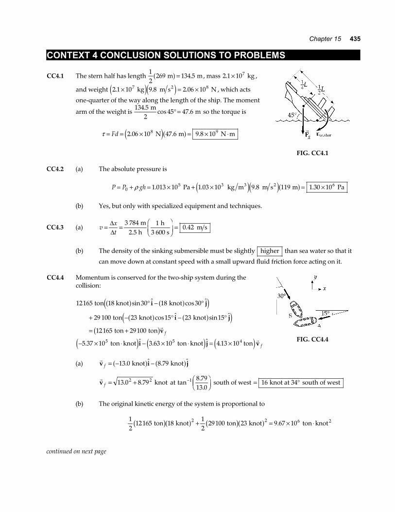
CC4.1 The stern half has length 12
269 134 5 m ma f = . , mass 2 1 107. × kg ,
and weight 2 1 10 9 8 2 06 107 8. . .× = × kg m s N2e je j , which acts
one-quarter of the way along the length of the ship. The moment
arm of the weight is 134 5
45 47 6.
cos . m
2 m° = so the torque is
τ = = × = × ⋅Fd 2 06 10 47 6 9 8 108 9. . . N m N me ja f r
FIG. CC4.1 CC4.2 (a) The absolute pressure is
P P gh= + = × + × = ×05 3 61 013 10 1 03 10 9 8 119 1 30 10ρ . . . . Pa kg m m s m Pa3 2e je ja f
(b) Yes, but only with specialized equipment and techniques.
CC4.3 (a) vxt
= ∆∆
=FHG
IKJ =
3 784 10 42
m2.5 h
h3 600 s
m s.
(b) The density of the sinking submersible must be slightly higher than sea water so that it
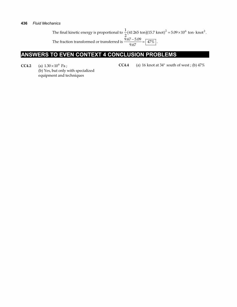
can move down at constant speed with a small upward fluid friction force acting on it. CC4.4 Momentum is conserved for the two-ship system during the
collision:
12165 30 18 30
29 100 23 15 23 15
12165 29100
5 37 10 3 63 10 4 13 105 5 4
ton 18 knot knot
ton knot knot
ton ton
ton knot ton knot ton
a f a fe ja f a fe j
b ge j e j e j
sin $ cos $
cos $ sin $
. $ . $ .
° − °
+ − ° − °
= +
− × ⋅ − × ⋅ = ×
i j
i j
v
i j v
r
rf
f
FIG. CC4.4
(a)
rv i jf = − −13 0 8 79. $ . $ knot knota f a f
rv f = +13 0 8 792 2. . knot at tan
..
− FHGIKJ
1 8 7913 0
south of west = °16 knot at 34 south of west
(b) The original kinetic energy of the system is proportional to
12
12165 1812
29100 23 9 67 102 2 6 ton knot ton knot ton knot 2b ga f b ga f+ = × ⋅.
continued on next page
436 Fluid Mechanics
The final kinetic energy is proportional to 12
41 265 15 7 5 09 102 6 ton knot ton knot2b ga f. .= × ⋅ .
The fraction transformed or transferred is 9 67 5 09
9 6747%
. ..− = .
ANSWERS TO EVEN CONTEXT 4 CONCLUSION PROBLEMS CC4.2 (a) 1 30 106. × Pa ; (b) Yes, but only with specialized
equipment and techniques
CC4.4 (a) 16 knot at 34 south of west° ; (b) 47%


