Embed Size (px)
Citation preview
DEI
MVS B N IN
VIGET
EV
VET
TES
EN
NOV
TAM
TVM
Introduction Carburation Fin’s Heat Transfer External Aerodynamics
Fluid Mechanics and Locomotion
Luigi Martinelli
Department of Mechanical and Aerospace EngineeringPrinceton University
2018-19
Role of Fluid Dynamics c©2018 by L. Martinelli
DEI
MVS B N IN
VIGET
EV
VET
TES
EN
NOV
TAM
TVM
Introduction Carburation Fin’s Heat Transfer External Aerodynamics
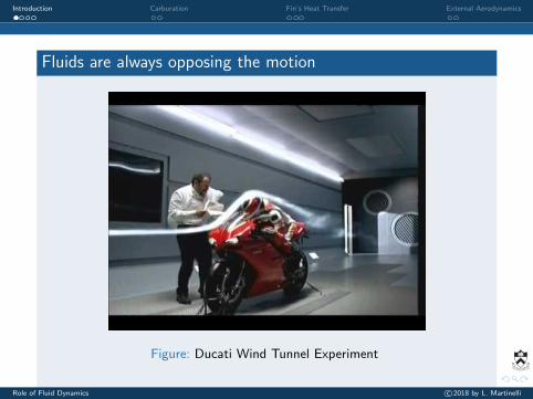
Fluids are always opposing the motion
Figure: Ducati Wind Tunnel Experiment
Role of Fluid Dynamics c©2018 by L. Martinelli
DEI
MVS B N IN
VIGET
EV
VET
TES
EN
NOV
TAM
TVM
Introduction Carburation Fin’s Heat Transfer External Aerodynamics
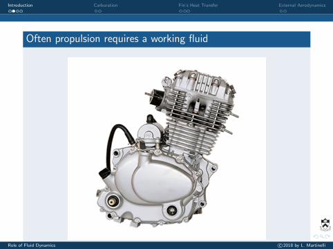
Often propulsion requires a working fluid
Role of Fluid Dynamics c©2018 by L. Martinelli
DEI
MVS B N IN
VIGET
EV
VET
TES
EN
NOV
TAM
TVM
Introduction Carburation Fin’s Heat Transfer External Aerodynamics
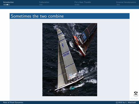
Sometimes the two combine
Role of Fluid Dynamics c©2018 by L. Martinelli
DEI
MVS B N IN
VIGET
EV
VET
TES
EN
NOV
TAM
TVM
Introduction Carburation Fin’s Heat Transfer External Aerodynamics
Fluid dynamics of carburation. Otto cycle engines used for thepropulsion motorcycle - either two-stroke or four-stroke - theyrequire a premixed air-fuel mixture ( commercial gasoline, specialgasolines for certain competitive uses or, in some rare cases , methylalcohol and/or ethyl ) that can be ignited by the spark produced bya spark plug .
Engine Cooling: require heat exchange between the engine and theoutside air (either direct or via a radiator).
Overview of Aerodynamic forces on ground vehicles. On astreighaway these are drag (opposing the motion), downforce.
Role of Fluid Dynamics c©2018 by L. Martinelli
DEI
MVS B N IN
VIGET
EV
VET
TES
EN
NOV
TAM
TVM
Introduction Carburation Fin’s Heat Transfer External Aerodynamics
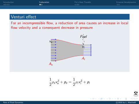
Venturi effect
For an incompressible flow, a reduction of area causes an increase in localflow velocity and a consequent decrease in pressure
Ae
Ai
ve
vi
Fuel
1
2ρev
2e + pe =
1
2ρiv
2i + pi
Role of Fluid Dynamics c©2018 by L. Martinelli
DEI
MVS B N IN
VIGET
EV
VET
TES
EN
NOV
TAM
TVM
Introduction Carburation Fin’s Heat Transfer External Aerodynamics
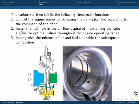
The carburetor then fulfills the following three main functions:1. control the engine power by adjusting the air intake flow according to
the command of the rider2. meter the fuel flow in the air flow aspirated maintaining the ratio
air/fuel to optimal values throughout the engine operating range3. homogenize the mixture of air and fuel to enable the subsequent
combustion
co, ormai, il predimensionamentosi effettua in base alla pratica co-struttiva ed all’esperienza consoli-data su una vasta gamma di motoci-cli e di tipi di motori. La definizionedel diametro viene poi effettuatamediante prove sul motore. Abbia-mo così, per esempio, che i piccoli
Il diffusore dei moderni carburatori motociclistici viene accuratamente studiato
per ridurre al minimo il disturbo al flusso aspirato da parte della valvola del
gas e della relativa sede. Qui sotto, vediamo il diffusore riportato di un
Dell’Orto VHSD con le due sottili feritoie entro le quali scorre la ghigliottina
che funge da elemento regolatore della portata d’aria.
Sotto, a destra la sezione di un carburatore VHSB nel quale è in evidenza la val-
vola gas piana, di ridotto spessore, che scorre in un diffusore riportato; qui a de-
stra, invece, la valvola cilindrica di un carburatore della serie PH... che mostra
una dimensione, nella direzione del flusso, ben maggiore che nel primo caso.
In entrambi i disegni possiamo notare, sotto i diffusori, i passaggi che portano
ai fori dei circuiti del minimo e di progressione, che illustreremo più avanti.
8
Role of Fluid Dynamics c©2018 by L. Martinelli
DEI
MVS B N IN
VIGET
EV
VET
TES
EN
NOV
TAM
TVM
Introduction Carburation Fin’s Heat Transfer External Aerodynamics
.
The temperature of the hot gases inside the cylinder can be as highas 2000 C (3630 F) .
The cylinder head is at a much lower temperature, therecommended maximum temperature measured at the spark plugbase being about 230 to 260 C (446 to 500 F).
The temperature on the inside of the wall can be as high as 315 to345 C (600 to 653 F).
Thus, the temperature difference between the outside of the cylinderhead wall (at the base of the fins) and the cooling air is severaltimes smaller than that from the combustion gas to the wall.
Role of Fluid Dynamics c©2018 by L. Martinelli
DEI
MVS B N IN
VIGET
EV
VET
TES
EN
NOV
TAM
TVM
Introduction Carburation Fin’s Heat Transfer External Aerodynamics
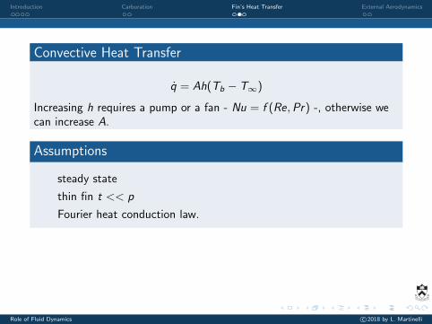
Convective Heat Transfer
q̇ = Ah(Tb − T∞)
Increasing h requires a pump or a fan - Nu = f (Re,Pr) -, otherwise wecan increase A.
Assumptions
steady state
thin fin t << p
Fourier heat conduction law.
Role of Fluid Dynamics c©2018 by L. Martinelli
DEI
MVS B N IN
VIGET
EV
VET
TES
EN
NOV
TAM
TVM
Introduction Carburation Fin’s Heat Transfer External Aerodynamics
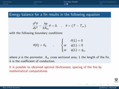
Energy balance for a fin results in the following equation
d2θ
dx2− hp
kAcsθ = 0. , θ = (T − T∞).
with the following boundary conditions
θ(0) = θb ,
θ(L) = 0
or q̇(L) = 0
or q̇(L) = q̇cv
where p is the perimeter, Acs cross sectional area, L the length of the fin,k is the coefficient of conduction.
It is possible to obtained optimal thicknesses, spacing of the fins bymathematical computations
Role of Fluid Dynamics c©2018 by L. Martinelli


![Locomotion [2014]](https://img.pdfslide.us/doc/110x75/5564e3eed8b42ad3488b4e94/locomotion-2014.jpg)


![Locomotion [2015]](https://img.pdfslide.us/doc/110x75/55d39c9ebb61ebfd268b46a2/locomotion-2015.jpg)