Embed Size (px)
Citation preview
ROTOFLUIDFluid Couplings
W
ESTCAR
MILANOITALY
MILANO - ITALY
Sheet
Date
3
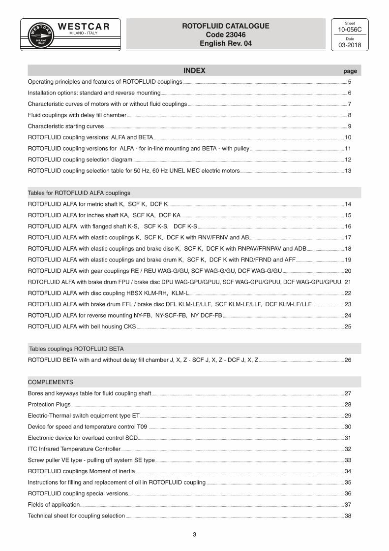
INDEX page
Operating principles and features of ROTOFLUID couplings ....................................................................................................................................................... 5
Installation options: standard and reverse mounting ........................................................................................................................................................................... 6
Characteristic curves of motors with or without fluid couplings .................................................................................................................................................. 7
Fluid couplings with delay fill chamber .......................................................................................................................................................................................................... 8
Characteristic starting curves ............................................................................................................................................................................................................................. 9
ROTOFLUID coupling versions: ALFA and BETA ............................................................................................................................................................................... 10
ROTOFLUID coupling versions for ALFA - for in-line mounting and BETA - with pulley ...................................................................................... 11
ROTOFLUID coupling selection diagram .................................................................................................................................................................................................. 12
ROTOFLUID coupling selection table for 50 Hz, 60 Hz UNEL MEC electric motors ............................................................................................... 13
Tables for ROTOFLUID ALFA couplings
ROTOFLUID ALFA for metric shaft K, SCF K, DCF K ................................................................................................................................................................. 14
ROTOFLUID ALFA for inches shaft KA, SCF KA, DCF KA ..................................................................................................................................................... 15
ROTOFLUID ALFA with flanged shaft K-S, SCF K-S, DCF K-S ...................................................................................................................................... 16
ROTOFLUID ALFA with elastic couplings K, SCF K, DCF K with RNV/FRNV and AB ....................................................................................... 17
ROTOFLUID ALFA with elastic couplings and brake disc K, SCF K, DCF K with RNPAV/FRNPAV and ADB .................................. 18
ROTOFLUID ALFA with elastic couplings and brake drum K, SCF K, DCF K with RND/FRND and AFF ............................................ 19
ROTOFLUID ALFA with gear couplings RE / REU WAG-G/GU, SCF WAG-G/GU, DCF WAG-G/GU ........................................................ 20
ROTOFLUID ALFA with brake drum FPU / brake disc DPU WAG-GPU/GPUU, SCF WAG-GPU/GPUU, DCF WAG-GPU/GPUU ...21
ROTOFLUID ALFA with disc coupling HBSX KLM-RH, KLM-L .............................................................................................................................................. 22
ROTOFLUID ALFA with brake drum FFL / brake disc DFL KLM-LF/LLF, SCF KLM-LF/LLF, DCF KLM-LF/LLF ............................. 23
ROTOFLUID ALFA for reverse mounting NY-FB, NY-SCF-FB, NY DCF-FB ............................................................................................................... 24
ROTOFLUID ALFA with bell housing CKS .............................................................................................................................................................................................. 25
Tables couplings ROTOFLUID BETA
ROTOFLUID BETA with and without delay fill chamber J, X, Z - SCF J, X, Z - DCF J, X, Z .............................................................................. 26
COMPLEMENTS
Bores and keyways table for fluid coupling shaft ................................................................................................................................................................................ 27
Protection Plugs .......................................................................................................................................................................................................................................................... 28
Electric-Thermal switch equipment type ET ........................................................................................................................................................................................... 29
Device for speed and temperature control T09 ................................................................................................................................................................................... 30
Electronic device for overload control SCD ............................................................................................................................................................................................. 31
ITC Infrared Temperature Controller............................................................................................................................................................................................................. 32
Screw puller VE type - pulling off system SE type ............................................................................................................................................................................. 33
ROTOFLUID couplings Moment of inertia ............................................................................................................................................................................................... 34
Instructions for filling and replacement of oil in ROTOFLUID coupling .............................................................................................................................. 35
ROTOFLUID coupling special versions ...................................................................................................................................................................................................... 36
Fields of application .................................................................................................................................................................................................................................................. 37
Technical sheet for coupling selection ........................................................................................................................................................................................................ 38
ROTOFLUID CATALOGUECode 23046
English Rev. 04
10-056C
03-2018
MILANO - ITALY
Sheet
Date
4
INDEX OF TECHNICAL SHEETS page
10-002* EN ROTOFLUID coupling selection table for 50 Hz, 60 Hz UNEL MEC electric motors ...................................................... 13
10-019* EN Bores and keyways table for fluid coupling shaft ................................................................................................................................................................... 27
10-035* EN ROTOFLUID couplings Moment of inertia .................................................................................................................................................................................. 34
10-037* EN Operating principles and features of ROTOFLUID couplings ......................................................................................................................................... 5
10-038* EN Installation options: standard and reverse mounting ............................................................................................................................................................. 6
10-052* EN Fields of application .................................................................................................................................................................................................................................... 37
10-057* EN ROTOFLUID coupling versions for ALFA - for in-line mounting and BETA - with pulley ......................................................................... 11
10-059* EN Technical sheet for coupling selection ........................................................................................................................................................................................... 38
10-061* EN Characteristic curves of motors with or without fluid couplings ..................................................................................................................................... 7
10-080* EN Characteristic starting curves ................................................................................................................................................................................................................. 9
10-100* EN ROTOFLUID coupling selection diagram .................................................................................................................................................................................... 12
10-141* EN Fluid couplings with delay fill chamber ............................................................................................................................................................................................. 8
10-180* EN ROTOFLUID coupling versions: ALFA and BETA ................................................................................................................................................................. 10
10-190* EN Instructions for replacement and variation of oil quantity ................................................................................................................................................ 35
10-195* EN ROTOFLUID coupling special versions ........................................................................................................................................................................................ 36
45-015* EN ROTOFLUID ALFA for metric shaft K, SCF K, DCF K.................................................................................................................................................... 14
45-017* EN ROTOFLUID ALFA for inches shaft KA, SCF KA, DCF KA ........................................................................................................................................ 15
45-020* EN ROTOFLUID ALFA with flanged hub K-S, SCF K-S, DCF K-S ............................................................................................................................. 16
45-090* EN ROTOFLUID ALFA with elastic coupling K, SCF K, DCF K with RNV/FRNV e AB .................................................................................. 17
45-091* EN ROTOFLUID ALFA with elastic element and brake disc K, SCF K, DCF K with RNPAV/FRNPAV e ADB................................ 18
45-093* EN ROTOFLUID ALFA with elastic element and brake drum K, SCF K, DCF K with RND/FRND e AFF ........................................ 19
45-113* EN ROTOFLUID ALFA with gear couplings RE / REU WAG-G/GU, SCF WAG-G/GU, DCF WAG-G/GU ........................................... 20
45-120* EN ROTOFLUID ALFA with brake drum FPU / brake disc DPU WAG-GPU/GPUU, SCF WAG-GPU/GPUU, DCF WAG-GPU/GPUU .... 21
45-215* EN ROTOFLUID BETA with and without delay fill chamber J, X, Z - SCF J, X, Z - DCF J, X, Z ............................................. 26
45-281* EN ROTOFLUID ALFA with bell housing CKS ......................................................................................................................................................................... 25
45-300* EN ROTOFLUID ALFA with disc coupling HBSX KLM-RH, KLM-L ..................................................................................................................... 22
45-305* EN ROTOFLUID ALFA with brake drum FFL / brake disc DFL KLM-LF/LLF, SCF KLM-LF/LLF, DCF KLM-LF/LLF ................ 23
45-400* EN ROTOFLUID ALFA for reverse mounting NY-FB, NY-SCF-FB, NY DCF-FB .................................................................................................. 24
80-004* EN Electric-Thermal switch equipment type ET ............................................................................................................................................................................. 29
80-022* EN Electronic device for overload control SCD ............................................................................................................................................................................... 31
80-035* EN Protection Plugs ............................................................................................................................................................................................................................................. 28
80-062* EN Device for speed and temperature control T09 ....................................................................................................................................................................... 30
80-065* EN ITC: Infrared Temperature Controller .............................................................................................................................................................................................. 32
90-005* EN Screw puller VE type - pulling off system SE type ............................................................................................................................................................... 33
ROTOFLUID CATALOGUECode 23046
English Rev. 04
10-056C EN
03-2018
MILANO - ITALY
Sheet
Date
5
10-137A EN
01-2017
OPERATING PRINCIPLES AND FEATURESOF ROTOFLUID COUPLING
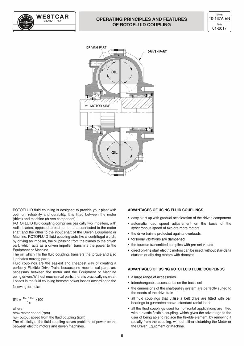
ROTOFLUID fluid coupling is designed to provide your plant with optimum reliability and durability. It is fitted between the motor (drive) and machine (driven component).ROTOFLUID fluid coupling comprises basically two impellers, with radial blades, opposed to each other, one connected to the motor shaft and the other to the input shaft of the Driven Equipment or Machine. ROTOFLUID fluid coupling acts like a centrifugal clutch, by driving an impeller, the oil passing from the blades to the driven part, which acts as a driven impeller, transmits the power to the Equipment or Machine.The oil, which fills the fluid coupling, transfers the torque and also lubricates moving parts.Fluid couplings are the easiest and cheapest way of creating a perfectly Flexible Drive Train, because no mechanical parts are necessary between the motor and the Equipment or Machine being driven. Without mechanical parts, there is practically no wear.Losses in the fluid coupling become power losses according to the
following formula:
S% = nm - nu x100 nm
where:nm= motor speed (rpm)nu= output speed from the fluid coupling (rpm)The elasticity of the fluid coupling solves problems of power peaks between electric motors and driven machines.
ADVANTAGES OF USING FLUID COUPLINGS
• easy start-up with gradual acceleration of the driven component
• automatic load speed adjustement on the basis of the synchronous speed of two ore more motors
• the drive train is protected againts overloads
• torsional vibrations are dampened
• the tourque transmitted complies with pre-set values
• direct on-line start electric motors can be used, without star-delta starters or slip-ring motors with rheostat
ADVANTAGES OF USING ROTOFLUID FLUID COUPLINGS
• a large range of accessories
• interchangeable accessories on the basic cell
• the dimensions of the shaft-pulley system are perfectly suited to the needs of the drive train
• all fluid couplings that utilise a belt drive are fitted with ball bearings to guarantee above- standard radial loads
• all the fluid couplings used for horizontal applications are fitted with a elastic flexible coupling, which gives the advantage to the user of being able to replace the flexible element, by removing it radially from the coupling, without either disturbing the Motor or the Driven Equipment or Machine.
MOTOR SIDE
DRIVEN PARTDRIVING PART
OIL
OIL
MILANO - ITALY
Sheet
Date
6
10-138B EN
01-2017
INSTALLATIONOPTIONS
STANDARD MOUNTING REVERSE MOUNTING
INPUT
INTERNAL PART
OUTPUT
EXTERNAL PART
INTERNAL PART
INPUT
EXTERNAL PART
OUTPUT
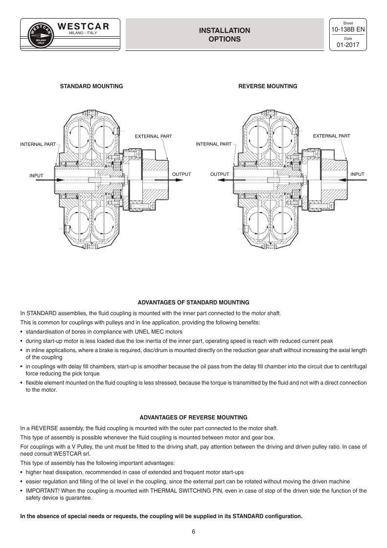
ADVANTAGES OF STANDARD MOUNTING
In STANDARD assemblies, the fluid coupling is mounted with the inner part connected to the motor shaft.
This is common for couplings with pulleys and in line application, providing the following benefits:
• standardisation of bores in compliance with UNEL MEC motors
• during start-up motor is less loaded due the low inertia of the inner part, operating speed is reach with reduced current peak
• in inline applications, where a brake is required, disc/drum is mounted directly on the reduction gear shaft without increasing the axial length of the coupling
• in couplings with delay fill chambers, start-up is smoother because the oil pass from the delay fill chamber into the circuit due to centrifugal force reducing the pick torque
• flexible element mounted on the fluid coupling is less stressed, because the torque is transmitted by the fluid and not with a direct connection to the motor.
ADVANTAGES OF REVERSE MOUNTING
In a REVERSE assembly, the fluid coupling is mounted with the outer part connected to the motor shaft.
This type of assembly is possible whenever the fluid coupling is mounted between motor and gear box.
For couplings with a V Pulley, the unit must be fitted to the driving shaft, pay attention between the driving and driven pulley ratio. In case of need consult WESTCAR srl.
This type of assembly has the following important advantages:
• higher heat dissipation, recommended in case of extended and frequent motor start-ups
• easier regulation and filling of the oil level in the coupling, since the external part can be rotated without moving the driven machine
• IMPORTANT! When the coupling is mounted with THERMAL SWITCHING PIN, even in case of stop of the driven side the function of the safety device is guarantee.
In the absence of special needs or requests, the coupling will be supplied in its STANDARD configuration.
MILANO - ITALY
Sheet
Date
7
10-061A EN
01-2017
CHARACTERISTICCURVES
START-UP WITHOUT FLUID COUPLING
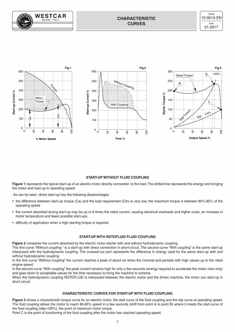
Figure 1 represents the typical start-up of an electric motor directly connected to the load. The dotted line represents the energy lost bringing the motor and load up to operating speed.
As can be seen, direct start-up has the following disadvantages:
• the difference between start-up torque (Ca) and the load requirement (Cm) is very low; the maximum torque is between 80%-85% of the operating speed
• the current absorbed during start-up may be up to 6 times the rated current, causing electrical overloads and higher costs, an increase in motor temperature and fewer possible start-ups.
• difficulty of application when a high starting torque is required.
START-UP WITH ROTOFLUID FLUID COUPLING
Figure 2 compares the current absorbed by the electric motor starter with and without hydrodynamic coupling.The first curve “Without coupling “ is a start-up with direct connection in short-circuit. The second curve “With coupling” is the same start-up interposed with the hydrodynamic coupling. The crossed-out part represents the difference in energy used for the same start-up with and without hydrodynamic coupling.In the first curve “Without coupling” the current reaches a peak of about six times the nominal and persists with high values up to the rated engine speed.In the second curve “With coupling” the peak current remains high for only a few seconds (energy required to accelerate the motor rotor only) and goes down to acceptable values for the time necessary to bring the machine to scheme.When the hydrodynamic coupling ROTOFLUID is interposed between the electric motor and the driven machine, the motor can start-up in short circuit.
CHARACTERISTIC CURVES FOR START-UP WITH FLUID COUPLING
Figure 3 shows a characteristic torque curve for an electric motor, the stall curve of the fluid coupling and the slip curve at operating speed. The fluid coupling allows the motor to reach 80-85% speed in a few seconds (shift from point A to point B) where it meets the stall curve of the fluid coupling (slip=100%), the point of maximum motor torque.Point C is the point of functioning of the fluid coupling after the motor has reached operating speed.
A
0
100
200
300
400
500
600
0 20 40 60 80 100
Sta
rt-u
p C
urr
ent
%
% Motor Speed
Fig.1
Ca C
m
MotorTorque
Current
0
100
200
300
400
500
600
0 20 40 60 80 100
Sta
rt-u
p C
urr
ent
%
Time %
Fig.2
Without Coupling
With Coupling
0
50
100
150
200
250
300
0 20 40 60 80 100
Sta
rter
To
rqu
e %
Output Speed %
Fig.3
Slip2-6%
Stall T
orqu
e
100%B
C
Motor Torque
MILANO - ITALY
Sheet
Date
8
10-141A EN
01-2017
FLUID COUPLINGSWITH DELAY CHAMBER
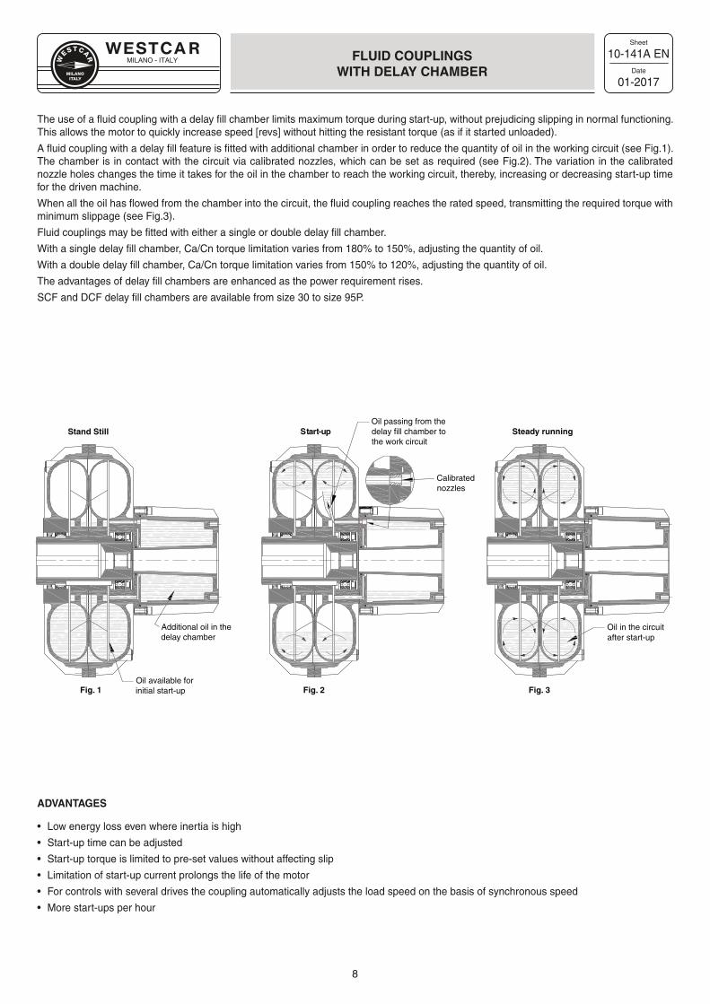
The use of a fluid coupling with a delay fill chamber limits maximum torque during start-up, without prejudicing slipping in normal functioning. This allows the motor to quickly increase speed [revs] without hitting the resistant torque (as if it started unloaded).
A fluid coupling with a delay fill feature is fitted with additional chamber in order to reduce the quantity of oil in the working circuit (see Fig.1). The chamber is in contact with the circuit via calibrated nozzles, which can be set as required (see Fig.2). The variation in the calibrated nozzle holes changes the time it takes for the oil in the chamber to reach the working circuit, thereby, increasing or decreasing start-up time for the driven machine.
When all the oil has flowed from the chamber into the circuit, the fluid coupling reaches the rated speed, transmitting the required torque with minimum slippage (see Fig.3).
Fluid couplings may be fitted with either a single or double delay fill chamber.
With a single delay fill chamber, Ca/Cn torque limitation varies from 180% to 150%, adjusting the quantity of oil.
With a double delay fill chamber, Ca/Cn torque limitation varies from 150% to 120%, adjusting the quantity of oil.
The advantages of delay fill chambers are enhanced as the power requirement rises.
SCF and DCF delay fill chambers are available from size 30 to size 95P.
ADVANTAGES
• Low energy loss even where inertia is high
• Start-up time can be adjusted
• Start-up torque is limited to pre-set values without affecting slip
• Limitation of start-up current prolongs the life of the motor
• For controls with several drives the coupling automatically adjusts the load speed on the basis of synchronous speed
• More start-ups per hour
Oil available forinitial start-up
Additional oil in thedelay chamber
Oil passing from thedelay fill chamber tothe work circuit
Oil in the circuitafter start-up
Stand Still Start-up Steady running
Fig. 1 Fig. 2 Fig. 3
Calibratednozzles
MILANO - ITALY
Sheet
Date
9
10-080A EN
01-2017
CHARACTERISTICSTARTING CURVES
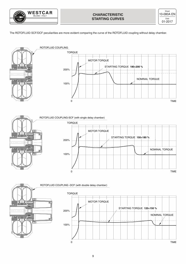
The ROTOFLUID SCF/DCF peculiarities are more evident comparing the curve of the ROTOFLUID coupling without delay chamber.
ROTOFLUID COUPLING -DCF (with double delay chamber)
ROTOFLUID COUPLING-SCF (with single delay chamber)
MOTOR TORQUE
ROTOFLUID COUPLING
100%
200%
0
200%
100%
200%
100%
STARTING TORQUE 180÷200 %
NOMINAL TORQUE
MOTOR TORQUE
STARTING TORQUE 150÷180 %
NOMINAL TORQUE
MOTOR TORQUE
STARTING TORQUE 120÷150 %
NOMINAL TORQUE
TORQUE
TORQUE
TORQUE
0
0 TIME
TIME
TIME
MILANO - ITALY
Sheet
Date
10
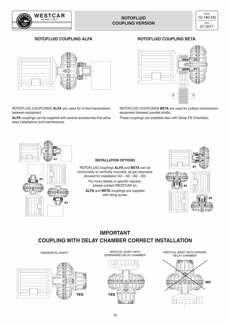
YESYES
NO
HORIZONTAL SHAFT VERTICAL SHAFT WITHDOWNWARD DELAY CHAMBER
VERTICAL SHAFT WITH UPWARDDELAY CHAMBER
A1
A2
A3
B1
B2
B3
10-180 EN
01-2017
ROTOFLUIDCOUPLING VERSION
ROTOFLUID COUPLING ALFA ROTOFLUID COUPLING BETA
ROTOFLUID COUPLINGS ALFA are used for in-line transmission between equipment.
ALFA couplings can be supplied with several accessories that allow easy installations and maintenance.
ROTOFLUID COUPLINGS BETA are used for pulleys transmission equipment between parallel shafts.
These couplings are available also with Delay Fill Chambers.
INSTALLATION OPTIONS
ROTOFLUID couplings ALFA and BETA can be horizontally or vertically mounted, as per examples
showed for installation A2 – A3 – B2 – B3.
For more details or specific request,please contact WESTCAR srl.
ALFA and BETA couplings are suppliedwith fixing screw.
IMPORTANTCOUPLING WITH DELAY CHAMBER CORRECT INSTALLATION
MILANO - ITALY
Sheet
Date
11
10-180 EN
01-2017
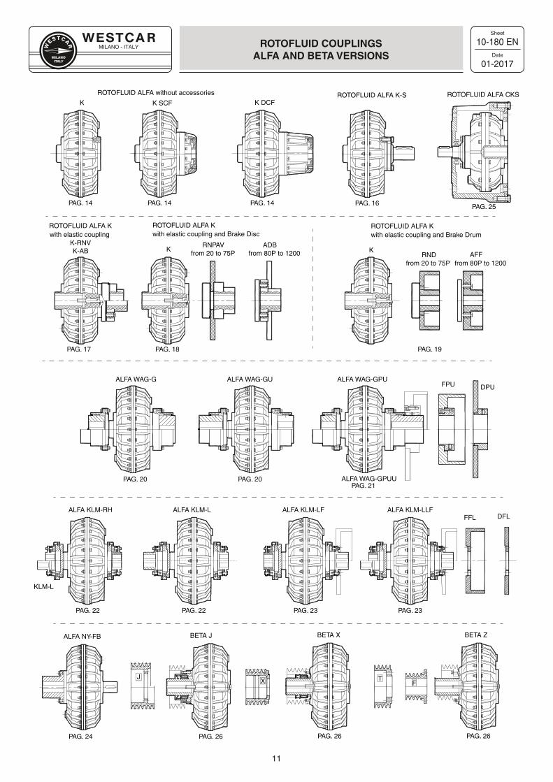
ROTOFLUID COUPLINGSALFA AND BETA VERSIONS
PAG. 22
ROTOFLUID ALFA K
ROTOFLUID ALFA without accessories
ROTOFLUID ALFA K
ROTOFLUID ALFA K-S
with elastic coupling and Brake Disc with elastic coupling and Brake Drum
K K DCFROTOFLUID ALFA CKS
K RNPAVfrom 20 to 75P
ALFA WAG-GFPU DPU
ALFA WAG-GU ALFA WAG-GPU
ALFA WAG-GPUU
ALFA KLM-RHFFL DFL
ALFA KLM-L ALFA KLM-LF
K-AB K
K SCF
PAG. 14 PAG. 14 PAG. 14 PAG. 16 PAG. 25
PAG. 18 PAG. 19
PAG. 20 PAG. 20PAG. 21
ALFA KLM-LLF
PAG. 22 PAG. 23 PAG. 23
ADBfrom 80P to 1200 RND
from 20 to 75P AFFfrom 80P to 1200
KLM-L
PAG. 17
ROTOFLUID ALFA Kwith elastic coupling
K-RNV
TFX
J
BETA Z
PAG. 26
BETA X
PAG. 26
BETA J
PAG. 26PAG. 24
ALFA NY-FB
MILANO - ITALY
Sheet
Date
12
10-100C EN
01-2017
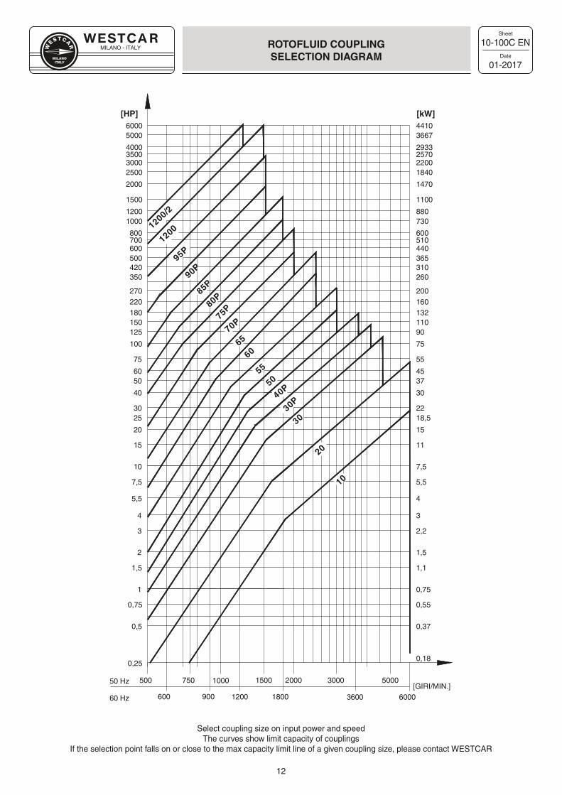
ROTOFLUID COUPLINGSELECTION DIAGRAM
Select coupling size on input power and speedThe curves show limit capacity of couplings
If the selection point falls on or close to the max capacity limit line of a given coupling size, please contact WESTCAR
60 Hz 600 6000
2000 5000500
4000
5000
2933
36676000 4410
750 1000 30001500
0,25
0,5
1
0,75
1,5
3
2
4
7,5
5,5
10
600
20
15
2530
40
5060
75
150
100
125
180220270
350
500420
1000
800700
1200
1500
2000
2500
[HP]
3000
50 Hz
0,37
0,75
0,55
1,1
2,2
1,5
3
5,5
4
7,5
440
15
11
18,522
30
3745
55
110
75
90
132160200
260
365310
730
600510
880
1100
1470
1840
[kW]
2200
0,18
[GIRI/MIN.]
25703500
900 1200 1800 3600
1200/2
1200
10
20
3030P
40P50
5560
6570P
75P
80P85P
90P95P
MILANO - ITALY
Sheet
Date
13
10-002B EN
01-2017
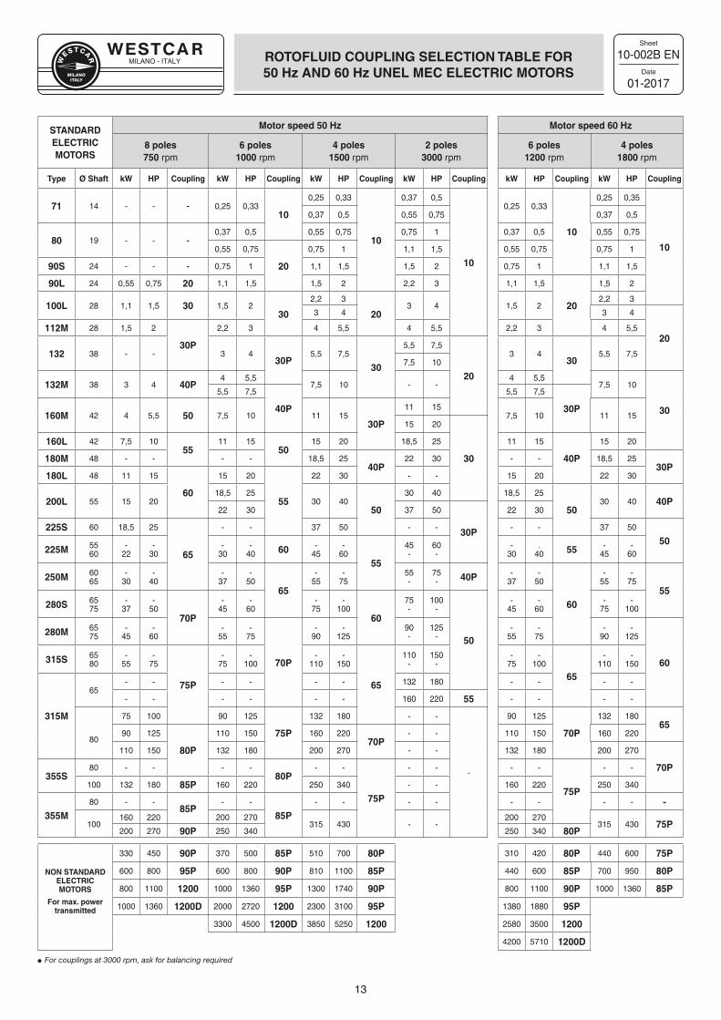
ROTOFLUID COUPLING SELECTION TABLE FOR50 Hz AND 60 Hz UNEL MEC ELECTRIC MOTORS
STANDARDELECTRICMOTORS
Motor speed 50 Hz Motor speed 60 Hz
8 poles 750 rpm
6 poles1000 rpm
4 poles1500 rpm
2 poles3000 rpm
6 poles1200 rpm
4 poles1800 rpm
Type Ø Shaft kW HP Coupling kW HP Coupling kW HP Coupling kW HP Coupling kW HP Coupling kW HP Coupling
71 14 - - - 0,25 0,3310
0,25 0,33
10
0,37 0,5
10
0,25 0,33
10
0,25 0,35
10
0,37 0,5 0,55 0,75 0,37 0,5
80 19 - - -0,37 0,5 0,55 0,75 0,75 1 0,37 0,5 0,55 0,75
0,55 0,75
20
0,75 1 1,1 1,5 0,55 0,75 0,75 1
90S 24 - - - 0,75 1 1,1 1,5 1,5 2 0,75 1 1,1 1,5
90L 24 0,55 0,75 20 1,1 1,5 1,5 2 2,2 3 1,1 1,5
20
1,5 2
100L 28 1,1 1,5 30 1,5 230
2,2 3
203 4 1,5 2
2,2 3
3 4 3 4
20112M 28 1,5 2
30P
2,2 3 4 5,5 4 5,5 2,2 3 4 5,5
132 38 - - 3 430P
5,5 7,5
30
5,5 7,5
20
3 430
5,5 7,57,5 10
132M 38 3 4 40P4 5,5
7,5 10 - -4 5,5
7,5 10
30
5,5 7,5
40P
5,5 7,5
30P160M 42 4 5,5 50 7,5 10 11 15
30P
11 157,5 10 11 15
15 20
30
160L 42 7,5 1055
11 1550
15 20 18,5 25 11 15
40P
15 20
180M 48 - - - - 18,5 2540P
22 30 - - 18,5 2530P
180L 48 11 15
60
15 20
55
22 30 - - 15 20 22 30
200L 55 15 2018,5 25
30 4050
30 40 18,5 25
5030 40 40P
22 30 37 50
30P
22 30
225S 60 18,5 25
65
- - 37 50 - - - - 37 50
50225M 55
60-
22-
30-
30-
40 60 -45
-60
55
45-
60-
-30
.40 55 -
45-
60
250M 6065
-30
-40
-37
-50
65
-55
-75
55-
75- 40P -
37-
50
60
-55
-75
55280S 65
75-
37-
5070P
-45
-60
-75
-100
60
75-
100-
50
-45
-60
-75
-100
280M 6575
-45
-60
-55
-75
70P
-90
-125
90-
125-
-55
-75
-90
-125
60315S 6580
-55
-75
75P
-75
-100
-110
-150
65
110-
150-
-75
-100
65
-110
-150
315M
65- - - - - - 132 180 - - - -
- - - - - - 160 220 55 - - - -
80
75 100 90 125
75P
132 180 - -
-
90 125
70P
132 18065
90 125
80P
110 150 160 22070P
- - 110 150 160 220
110 150 132 180 200 270 - - 132 180 200 270
70P355S
80 - - - -80P
- -
75P
- - - -
75P
- -
100 132 180 85P 160 220 250 340 - - 160 220 250 340
355M80 - -
85P- -
85P- - - - - - - - -
100160 220 200 270
315 430 - -200 270
315 430 75P200 270 90P 250 340 250 340 80P
NON STANDARD ELECTRICMOTORS
For max. power transmitted
330 450 90P 370 500 85P 510 700 80P 310 420 80P 440 600 75P
600 800 95P 600 800 90P 810 1100 85P 440 600 85P 700 950 80P
800 1100 1200 1000 1360 95P 1300 1740 90P 800 1100 90P 1000 1360 85P
1000 1360 1200D 2000 2720 1200 2300 3100 95P 1380 1880 95P
3300 4500 1200D 3850 5250 1200 2580 3500 1200
4200 5710 1200D
For couplings at 3000 rpm, ask for balancing required
MILANO - ITALY
Sheet
Date
14
45-015E EN
03-2018
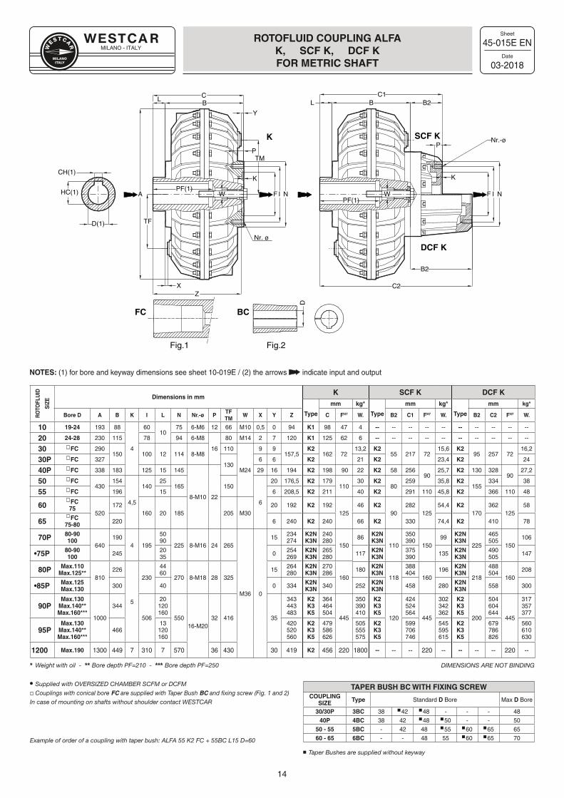
ROTOFLUID COUPLING ALFAK, SCF K, DCF KFOR METRIC SHAFT
NOTES: (1) for bore and keyway dimensions see sheet 10-019E / (2) the arrows indicate input and output
RO
TOFL
UID
SIZE
Dimensions in mmK SCF K DCF K
Type
mm kg*
Type
mm kg*
Type
mm kg*
Bore D A B K I L N Nr.-ø PTFTM
W X Y Z C FH7 W. B2 C1 FH7 W. B2 C2 FH7 W.
10 19-24 193 88
4
6010
75 6-M6 12 66 M10 0,5 0 94 K1 98 47 4 -- -- -- -- -- -- -- -- -- --
20 24-28 230 115 78 94 6-M8
16
80 M14 2 7 120 K1 125 62 6 -- -- -- -- -- -- -- -- -- --
30 �FC 290150 100 12 114 8-M8
110
M24
9 9157,5
K2162 72
13,2 K255 217 72
15,6 K295 257 72
16,2
30P �FC 327130
6 6 K2 21 K2 23,4 K2 24
40P �FC 338 183 125 15 145
8-M10 22
29 16 194 K2 198 90 22 K2 58 25690
25,7 K2 130 32890
27,2
50 �FC430
154
4,5
14025
165 150
6
20 176,5 K2 179110
30 K280
259 35,8 K2155
334 38
55 �FC 196 15 6 208,5 K2 211 40 K2 291 110 45,8 K2 366 110 48
60�FC75
520172
160 20 185 205 M3020 192 K2 192
12546 K2
90282
12554,4 K2
170362
12558
65�FC
75-80 220 6 240 K2 240 66 K2 330 74,4 K2 410 78
70P 80-90100
640190
4 195
5090
225 8-M16 24 265
M36 0
15 234274
K2NK3N
240280
15086 K2N
K3N110
350390
15099 K2N
K3N225
465505
150106
•75P 80-90100 245 20
35 0 254269
K2NK3N
265280 117 K2N
K3N375390 135 K2N
K3N490505 147
80P Max.110Max.125**
810226
5
230
4460
270 8-M18 28 32515 264
280K2NK3N
270286
160180 K2N
K3N118
388404
160196 K2N
K3N218
488504
160208
•85P Max.125Max.130 300 40 0 334 K2N
K3N 340 252 K2NK3N 458 280 K2N
K3N 558 300
90PMax.130
Max.140**Max.160***
1000
344
506
20120160
55016-M20
32 416 35
343443483
K2K3K5
364464504
445
350390410
K2K3K5
120
424524564
445
302342362
K2K3K5
200
504604644
445
317357377
95PMax.130
Max.140**Max.160***
46613120160
420520560
K2K3K5
479586626
505555575
K2K3K5
599706746
545595615
K2K3K5
679786826
560610630
1200 Max.190 1300 449 7 310 7 570 36 430 30 419 K2 456 220 1800 -- -- -- 220 -- -- -- -- 220 --
Weight with oil - Bore depth PF=210 - Bore depth PF=250
Supplied with OVERSIZED CHAMBER SCFM or DCFM Couplings with conical bore FC are supplied with Taper Bush BC and fixing screw (Fig. 1 and 2)
In case of mounting on shafts without shoulder contact WESTCAR
Example of order of a coupling with taper bush: ALFA 55 K2 FC + 55BC L15 D=60
DIMENSIONS ARE NOT BINDING
PF(1)
ZX
A
TF
L
D(1)
CH(1)
HC(1)
TM
B
F NI
Nr. ø
Y
K
P
C
W
BL
PF(1)NIF
P
K
Nr.-ø
W
B2C1
B2
C2
K SCF K
DCF K
FC BCD
Fig.1 Fig.2
TAPER BUSH BC WITH FIXING SCREWCOUPLING
SIZE Type Standard D Bore Max D Bore
30/30P 3BC 38 42 48 - - - 4840P 4BC 38 42 48 50 - - 50
50 - 55 5BC - 42 48 55 60 65 6560 - 65 6BC - - 48 55 60 65 70
Taper Bushes are supplied without keyway
MILANO - ITALY
Sheet
Date
15
45-017A EN
03-2018
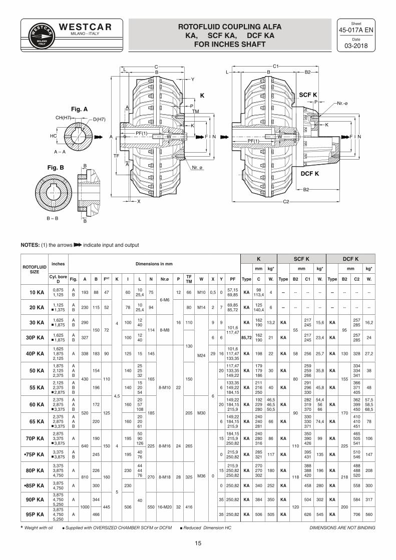
ROTOFLUID COUPLING ALFA KA, SCF KA, DCF KA
FOR INCHES SHAFT
NOTES: (1) the arrows indicate input and output
ROTOFLUIDSIZE
inches Dimensions in mmK SCF K DCF K
mm kg* mm kg* mm kg*
Cyl. bore D Fig. A B FH7 K I L N Nr.ø P TF
TM W X Y PF Type C W. Type B2 C1 W. Type B2 C2 W.
10 KA 0,8751,125
AB 193 88 47
4
60 1025,4 75
6-M6
12 66 M10 0,5 0 57,1569,85 KA 98
113,4 4 -- -- -- -- -- -- -- --
20 KA 1,125 1,375
AB 230 115 52 78 10
25,4 94
16
80 M14 2 7 69,8585,72 KA 125
140,4 6 -- -- -- -- -- -- -- --
30 KA 1,625 1,875
AB 290
150 72
100 1240
114 8-M8
110
M24
9 9101,6
117,47
KA 162190 13,2 KA
55
217245 15,6 KA
95
257285 16,2
30P KA 1,625 1,875
AB 327 100 12
40130
6 6 85,72 162190 21 KA 217
245 23,4 KA 257285 24
40P KA1,6251,875 2,125
A 338 183 90 125 15 145
8-M10 22
29 16101,6
117,47133,35
KA 198 22 KA 58 256 25,7 KA 130 328 27,2
50 KA1,8752,125 2,375
AAB
430
154
110
4,5
140252532
165 150
6
20117,47133,35149,22
KA179179186
30 KA
80
259259266
35,8 KA
155
334334341
38
55 KA2,1252,375 2,875
ABB
196 140152054
6133,35149,22184,15
KA211216250
40 KA291296330
45,8 KA366371405
48
60 KA2,3752,875 3,375
AAB
520
172
125
1602057108
185 205 M30
20149,22184,15215,9
KA192229280
46,546,550,5
KA
90
282319370
54,45666
KA
170
362399450
57,558,568,5
65 KA2,3752,875 3,375
AAB
220 160202061
6149,22184,15215,9
KA240240281
66 KA330330371
74,4 KA410410451
78
70P KA2,875 3,375 3,875
A
640
190
150 4
1955090126
225 8-M16 24 265
M36 0
15184,15215,9
250,82KA
240280316
86 KA
110
350390426
99 KA
225
465505541
106
•75P KA 3,375 3,875
AB 245 195 40
76 0 215,9250,82 KA 285
321 117 KA 395431 135 KA 510
546 147
80P KA3,3753,8754,750
A
810
226
160
5
230444476 270 8-M18 28 325
15215,9
250,82250,82
KA270270302
180 KA
118
388388420
196 KA
218
488488520
208
•85P KA 3,875 4,750 A 300 230
40
0 250,82 KA 340 252 KA 458 280 KA 558 300
90P KA3,8754,7505,250
A
1000
344
445 506 550 16-M20 32 416
35 250,82 KA 384 350 KA
120
504 302 KA
200
584 317
95P KA3,8754,7505,250
A 466 35 250,82 KA 506 505 KA 626 545 KA 706 560
Weight with oil Supplied with OVERSIZED CHAMBER SCFM or DCFM Reduced Dimension HC DIMENSIONS ARE NOT BINDING
PF(1)
X
A
TF
L
CH(H7)TM
B
F NI
Nr. ø
Y
K
P
C
W
BL
PF(1)NIF
P
K
Nr.-ø
W
B2C1
B2
C2
K SCF K
DCF K
Fig. A
Fig. B
D(H7)
A
A
B – B
B
B
A – A
HC
MILANO - ITALY
Sheet
Date
16
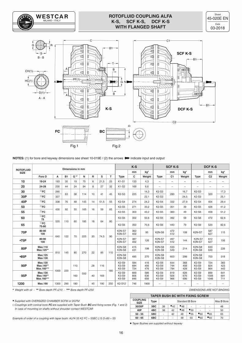
45-020E EN
03-2018
ROTOFLUID COUPLING ALFAK-S, SCF K-S, DCF K-S
WITH FLANGED SHAFT
NOTES: (1) for bore and keyway dimensions see sheet 10-019E / (2) the arrows indicate input and output
ROTOFLUIDSIZE
Dimensions in mmK-S SCF K-S DCF K-S
mm kg* mm kg* mm kg*
Foro D A B1 G h7 N R S T Type C Weight Type C1 Weight Type C2 Weight
10 19-24 193 35 19 75 6 21,5 25 K1-S1 133 4,3 -- -- -- -- -- --
20 24-28 230 44 24 94 8 27 32 K1-S2 169 6,6 -- -- -- -- -- --
30 �FC 29063 38 114 10 41 45 K2-S3 225
14,3 K2-S3280
16,7 K2-S3320
17,3
30P �FC 327 22,1 K2-S3 24,5 K2-S3 25,1
40P �FC 338 76 48 145 14 51,5 55 K2-S4 274 24,2 K2-S4 332 27,9 K2-S4 404 29,4
50 �FC430 92 55 165 16 59 65
K2-S5 271 33,2 K2-S5 351 39 K2-S5 426 41,2
55 �FC K2-S5 303 43,2 K2-S5 383 49 K2-S6 458 51,2
60�FC75
520 110 60 185 18 64 80K2-S6 302 50,6 K2-S5 392 59 K2-S6 472 62,6
65�FC
75-80 K2-S6 350 70,6 K2-S6 440 79 K2-S6 520 82,6
70P 80-90100
640 122 70 225 20 74,5 90
K2N-S7K3N-S7
362402 95 K2N-S6 472
512 108 K2N-S7 587627 115
•75P 80-90100
K2N-S7K3N-S7
387402 126 K2N-S7
K3N-S7497512 144 K2N-S7
K3N-S7612627 156
80P Max.110Max.125**
810 145 80 270 22 85 110
K2N-S8K3N-S8
415431 198 K2N-S8
K3N-S8533549 214 K2N-S8
K3N-S8633649 226
•85P Max.125Max.130
K2N-S8K3N-S8 485 270 K2N-S8
K3N-S8 603 298 K2N-S8K3N-S8 703 318
90PMax.130
Max.140**Max.160***
1000 220
110
550
28 116
180
K2-S9K3-S9K5-S9
584684724
416456476
K2-S9K3-S9K5-S9
644744784
368408428
K2-S9K3-S9K5-S9
724824864
383423443
95PMax.130
Max.140**Max.160***
160 40 169K2-S9K3-S9K5-S9
669806846
586636656
K2-S9K3-S9K5-S9
819926966
626676696
K2-S9K3-S9K5-S9
89910061046
641691711
1200 Max.190 1300 290 180 45 190 250 K2-S12 746 1900 -- -- -- -- -- --
Weight with oil - Bore depth PF=210 - Bore depth PF=250 DIMENSIONS ARE NOT BINDING
Supplied with OVERSIZED CHAMBER SCFM or DCFM Couplings with conical bore FC are supplied with Taper Bush BC and fixing screw (Fig. 1 and 2)
In case of mounting on shafts without shoulder contact WESTCAR
Example of order of a coupling with taper bush: ALFA 55 K2 FC + 55BC L15 D=60 + S5
APF(1)
D(1)
CH(1)
HC(1) G N
T
B
B
S
R
A - A
B1
C1C
A
A
B - BB1
C2
B1K-S
SCF K-S
DCF K-S
FC BCD
G
Fig.1 Fig.2
TAPER BUSH BC WITH FIXING SCREWCOUPLING
SIZE Type Standard D Bore Max D Bore
30/30P 3BC 38 42 48 - - - 4840P 4BC 38 42 48 50 - - 50
50 - 55 5BC - 42 48 55 60 65 6560 - 65 6BC - - 48 55 60 65 70
Taper Bushes are supplied without keyway
MILANO - ITALY
Sheet
Date
17
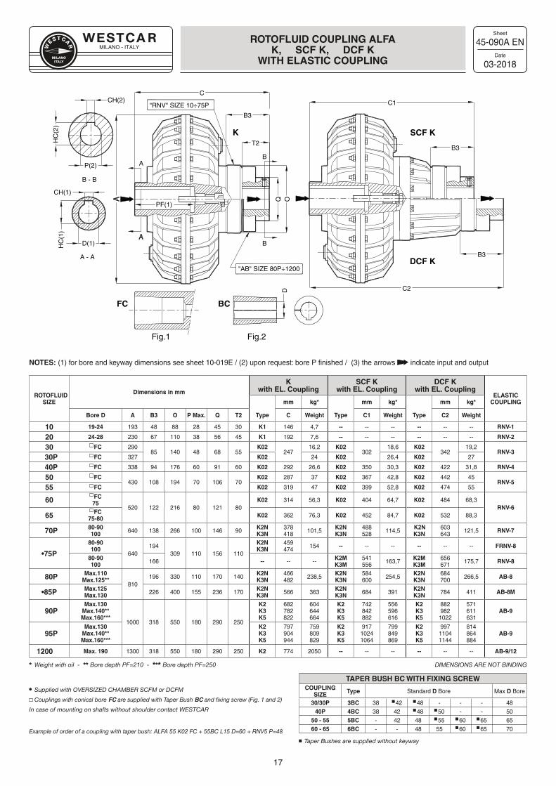
45-090A EN
03-2018
ROTOFLUID COUPLING ALFA K, SCF K, DCF K
WITH ELASTIC COUPLING
NOTES: (1) for bore and keyway dimensions see sheet 10-019E / (2) upon request: bore P finished / (3) the arrows indicate input and output
TAPER BUSH BC WITH FIXING SCREWCOUPLING
SIZE Type Standard D Bore Max D Bore
30/30P 3BC 38 42 48 - - - 4840P 4BC 38 42 48 50 - - 50
50 - 55 5BC - 42 48 55 60 65 6560 - 65 6BC - - 48 55 60 65 70
Taper Bushes are supplied without keyway
ROTOFLUIDSIZE
Dimensions in mm
Kwith EL. Coupling
SCF Kwith EL. Coupling
DCF Kwith EL. Coupling
ELASTIC COUPLING
Type
mm kg*
Type
mm kg*
Type
mm kg*
Bore D A B3 O P Max. Q T2 C Weight C1 Weight C2 Weight
10 19-24 193 48 88 28 45 30 K1 146 4,7 -- -- -- -- -- -- RNV-1
20 24-28 230 67 110 38 56 45 K1 192 7,6 -- -- -- -- -- -- RNV-2
30 �FC 29085 140 48 68 55
K02247
16,2 K02302
18,6 K02342
19,2RNV-3
30P �FC 327 K02 24 K02 26,4 K02 27
40P �FC 338 94 176 60 91 60 K02 292 26,6 K02 350 30,3 K02 422 31,8 RNV-4
50 �FC430 108 194 70 106 70
K02 287 37 K02 367 42,8 K02 442 45RNV-5
55 �FC K02 319 47 K02 399 52,8 K02 474 55
60�FC75
520 122 216 80 121 80K02 314 56,3 K02 404 64,7 K02 484 68,3
RNV-665
�FC75-80 K02 362 76,3 K02 452 84,7 K02 532 88,3
70P 80-90100 640 138 266 100 146 90 K2N
K3N378418 101,5 K2N
K3N488528 114,5 K2N
K3N603643 121,5 RNV-7
•75P
80-90100
640194
309 110 156 110
K2NK3N
459474 154 -- -- -- -- -- -- FRNV-8
80-90100 166 -- -- -- K2M
K3M541556 163,7 K2M
K3M656671 175,7 RNV-8
80P Max.110Max.125**
810196 330 110 170 140 K2N
K3N466482 238,5 K2N
K3N584600 254,5 K2N
K3N684700 266,5 AB-8
•85P Max.125Max.130 226 400 155 236 170 K2N
K3N 566 363 K2NK3N 684 391 K2N
K3N 784 411 AB-8M
90PMax.130
Max.140**Max.160***
1000 318 550 180 290 250
K2K3K5
682782822
604644664
K2K3K5
742842882
556596616
K2K3K5
882982
1022
571611631
AB-9
95PMax.130
Max.140**Max.160***
K2K3K5
797904944
759809829
K2K3K5
91710241064
799849869
K2K3K5
99711041144
814864884
AB-9
1200 Max. 190 1300 318 550 180 290 250 K2 774 2050 -- -- -- -- -- -- AB-9/12
Weight with oil - Bore depth PF=210 - Bore depth PF=250 DIMENSIONS ARE NOT BINDING
Supplied with OVERSIZED CHAMBER SCFM or DCFM
Couplings with conical bore FC are supplied with Taper Bush BC and fixing screw (Fig. 1 and 2)
In case of mounting on shafts without shoulder contact WESTCAR
Example of order of a coupling with taper bush: ALFA 55 K02 FC + 55BC L15 D=60 + RNV5 P=48
A
A
A - A
D(1)
CH(1)
B
B - B
B
B3
PF(1)
A
Q
P(2)
CH(2)
HC
(1)
C
C1
HC
(2)
B3
O
T2
C2
B3
K SCF K
DCF K
FC BC
"RNV" SIZE 10÷75P
"AB" SIZE 80P÷1200
D
Fig.1 Fig.2
MILANO - ITALY
Sheet
Date
18
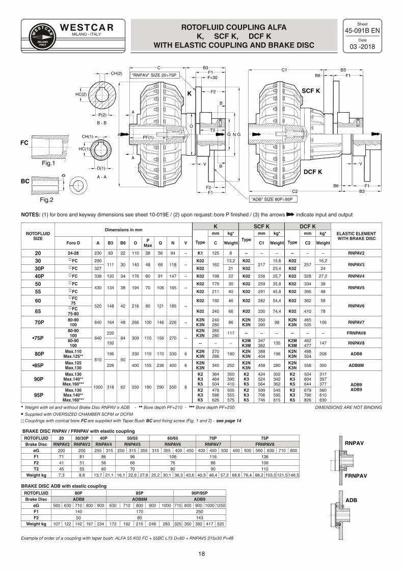
45-091B EN
03 -2018
ROTOFLUID COUPLING ALFA K, SCF K, DCF K
WITH ELASTIC COUPLING AND BRAKE DISC
ROTOFLUID SIZE
Dimensions in mmK SCF K DCF K
ELASTIC ELEMENT WITH BRAKE DISC
Type
mm kg*Type
mm kg*
Type
mm kg*
Foro D A B3 B6 O PMax Q N V C Weight C1 Weight C2 Weight
20 24-28 230 93 22 110 38 56 94 -- K1 125 6 -- -- -- -- -- -- RNPAV2
30 �FC 290111 30 140 48 68 118 --
K02162
13,2 K02217
15,6 K02257
16,2RNPAV3
30P �FC 327 K02 21 K02 23,4 K02 24
40P �FC 338 120 34 176 60 91 147 -- K02 198 22 K02 256 25,7 K02 328 27,2 RNPAV4
50 �FC430 134 38 194 70 106 165 --
K02 179 30 K02 259 35,8 K02 334 38RNPAV5
55 �FC K02 211 40 K02 291 45,8 K02 366 48
60�FC75
520 148 42 216 80 121 185 --K02 192 46 K02 282 54,4 K02 362 58
RNPAV665
�FC75-80 K02 240 66 K02 330 74,4 K02 410 78
70P 80-90100 640 164 48 266 100 146 226 -- K2N
K3N240280 86 K2N
K3N350390 99 K2N
K3N465505 106 RNPAV7
•75P80-90100
640220
84 309 110 156 270 --
K2N K3N
265280 117 -- -- -- -- -- -- FRNPAV8
80-90100 192 -- -- -- K2M
K3M347362 135 K2M
K3M462477 147 RNPAV8
80P Max.110Max.125**
810196
50330 110 170 330 6 K2N
K3N270286 180 K2N
K3N388404 196 K2N
K3N488504 208 ADB8
•85P Max.125Max.130 226 400 155 236 400 6 K2N
K3N 340 252 K2N K3N 458 280 K2N
K3N 558 300 ADB8M
90PMax.130
Max.140**Max.160***
1000 318 62 550 180 290 550 6
K2K3K5
364464504
350390410
K2K3K5
424524564
302342362
K2K3K5
504604644
317357377 ADB9
ADB9 95P
Max.130Max.140**Max.160***
K2K3K5
479586626
505555575
K2K3K5
599706746
545595615
K2K3K5
679786826
560610630
Weight with oil and without Brake Disc RNPAV o ADB - Bore depth PF=210 - Bore depth PF=250 DIMENSIONS ARE NOT BINDING Supplied with OVERSIZED CHAMBER SCFM or DCFM Couplings with conical bore FC are supplied with Taper Bush BC and fixing screw (Fig. 1 and 2) - see page 14
BRAKE DISC RNPAV / FRNPAV with elastic couplingROTOFLUID 20 30/30P 40P 50/55 60/65 70P 75PBrake Disc RNPAV2 RNPAV3 RNPAV4 RNPAV5 RNPAV6 RNPAV7 FRNPAV8
øG 200 200 250 315 250 315 355 315 355 400 450 400 450 500 450 500 560 630 710 800F1 71 81 86 96 106 116 136F2 41 51 56 66 76 86 106T2 45 55 60 70 80 90 110
Weight kg 7,3 8,6 13,7 21,1 16,1 22,6 27,6 25,2 30,1 36,3 43,6 40,5 48,4 57,2 68,6 76,4 88,2 103,5 121,5 146,5
BRAKE DISC ADB with elastic couplingROTOFLUID 80P 85P 90P/95PBrake Disc ADB8 ADB8M ADB9
øG 560 630 710 800 900 630 710 800 900 1000 710 800 900 1000 1250F1 140 170 250F2 50 80 143
Weight kg 107 122 142 167 234 172 192 215 248 283 325 350 382 417 520
Example of order of a coupling with taper bush: ALFA 55 K02 FC + 55BC L15 D=60 + RNPAV5 315x30 P=48
NOTES: (1) for bore and keyway dimensions see sheet 10-019E / (2) upon request: bore P finished / (3) the arrows indicate input and output
RNPAV
FRNPAV
ADB
A - A
D(1)
CH(1)
A
A
B - B
PF(1)
AP(2)
CH(2)
HC(1)
C C1
HC(2)
C2
GQ N
B
B
"ADB" SIZE 80P÷95P
F1
F2
F=30
T2
F2
F1
V
"RNPAV" SIZE 20÷75P F1
F1
V
B6
B6
B3 B3
B3
O
K SCF K
DCF K
FC
Fig.1
D
BC
Fig.2
MILANO - ITALY
Sheet
Date
19
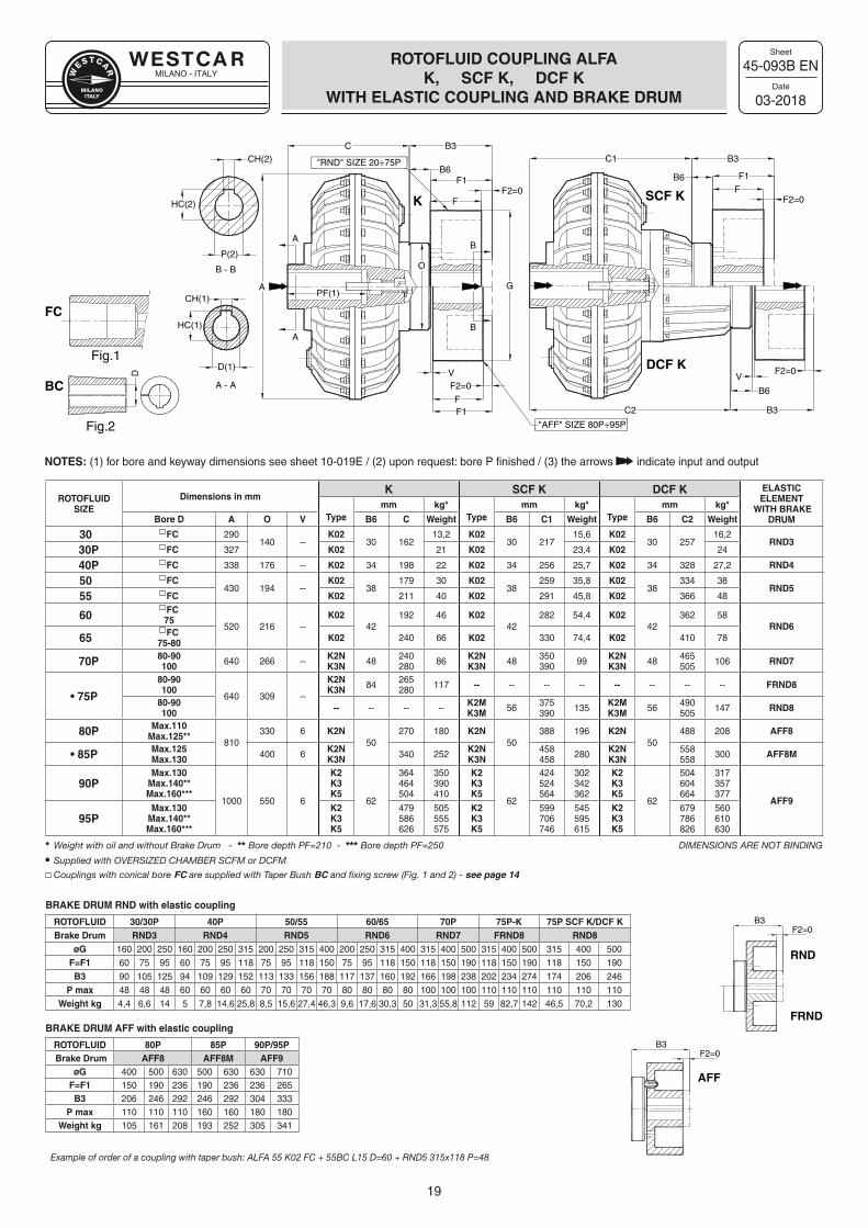
45-093B EN
03-2018
ROTOFLUID COUPLING ALFA K, SCF K, DCF K
WITH ELASTIC COUPLING AND BRAKE DRUM
NOTES: (1) for bore and keyway dimensions see sheet 10-019E / (2) upon request: bore P finished / (3) the arrows indicate input and output
ROTOFLUIDSIZE
Dimensions in mmK SCF K DCF K ELASTIC
ELEMENT WITH BRAKE
DRUMTypemm kg*
Typemm kg*
Typemm kg*
Bore D A O V B6 C Weight B6 C1 Weight B6 C2 Weight
30 �FC 290140 --
K0230 162
13,2 K0230 217
15,6 K0230 257
16,2RND3
30P �FC 327 K02 21 K02 23,4 K02 24
40P �FC 338 176 -- K02 34 198 22 K02 34 256 25,7 K02 34 328 27,2 RND4
50 �FC430 194 --
K0238
179 30 K0238
259 35,8 K0238
334 38RND5
55 �FC K02 211 40 K02 291 45,8 K02 366 48
60�FC75
520 216 --K02
42192 46 K02
42282 54,4 K02
42362 58
RND6 65
�FC75-80 K02 240 66 K02 330 74,4 K02 410 78
70P 80-90100 640 266 -- K2N
K3N 48 240280 86 K2N
K3N 48 350390 99 K2N
K3N 48 465505 106 RND7
• 75P
80-90100
640 309 --
K2NK3N 84 265
280 117 -- -- -- -- -- -- -- -- FRND8
80-90100 -- -- -- -- K2M
K3M 56 375390 135 K2M
K3M 56 490505 147 RND8
80P Max.110Max.125**
810330 6 K2N
50270 180 K2N
50388 196 K2N
50488 208 AFF8
• 85P Max.125Max.130 400 6 K2N
K3N 340 252 K2NK3N
458458 280 K2N
K3N558558 300 AFF8M
90PMax.130
Max.140**Max.160***
1000 550 6
K2K3K5
62
364464504
350390410
K2K3K5
62
424524564
302342362
K2K3K5
62
504604664
317357377
AFF9
95PMax.130
Max.140**Max.160***
K2K3K5
479586626
505555575
K2K3K5
599706746
545595615
K2K3K5
679786826
560610630
Weight with oil and without Brake Drum - Bore depth PF=210 - Bore depth PF=250 DIMENSIONS ARE NOT BINDING Supplied with OVERSIZED CHAMBER SCFM or DCFM
Couplings with conical bore FC are supplied with Taper Bush BC and fixing screw (Fig. 1 and 2) - see page 14
BRAKE DRUM RND with elastic coupling
ROTOFLUID 30/30P 40P 50/55 60/65 70P 75P-K 75P SCF K/DCF KBrake Drum RND3 RND4 RND5 RND6 RND7 FRND8 RND8
øG 160 200 250 160 200 250 315 200 250 315 400 200 250 315 400 315 400 500 315 400 500 315 400 500F=F1 60 75 95 60 75 95 118 75 95 118 150 75 95 118 150 118 150 190 118 150 190 118 150 190B3 90 105 125 94 109 129 152 113 133 156 188 117 137 160 192 166 198 238 202 234 274 174 206 246
P max 48 48 48 60 60 60 60 70 70 70 70 80 80 80 80 100 100 100 110 110 110 110 110 110Weight kg 4,4 6,6 14 5 7,8 14,6 25,8 8,5 15,6 27,4 46,3 9,6 17,6 30,3 50 31,3 55,8 112 59 82,7 142 46,5 70,2 130
BRAKE DRUM AFF with elastic coupling
ROTOFLUID 80P 85P 90P/95P Brake Drum AFF8 AFF8M AFF9
øG 400 500 630 500 630 630 710F=F1 150 190 236 190 236 236 265B3 206 246 292 246 292 304 333
P max 110 110 110 160 160 180 180Weight kg 105 161 208 193 252 305 341
Example of order of a coupling with taper bush: ALFA 55 K02 FC + 55BC L15 D=60 + RND5 315x118 P=48
AFF
B3F2=0
RND
FRND
B3F2=0
A - A
D(1)
CH(1)
A
A
B - B
PF(1)
A
P(2)
CH(2)
HC(1)
CC1
HC(2)
C2
O
B
B
FF2=0
B6
V
F1
F1
F2=0
F
B6
B6
"AFF" SIZE 80P÷95P
"RND" SIZE 20÷75P
B3B3
B3
V
G
F2=0FF1
F2=0D
K SCF K
DCF K
FC
BC
Fig.1
Fig.2
MILANO - ITALY
Sheet
Date
20
45-113H EN
03-2018
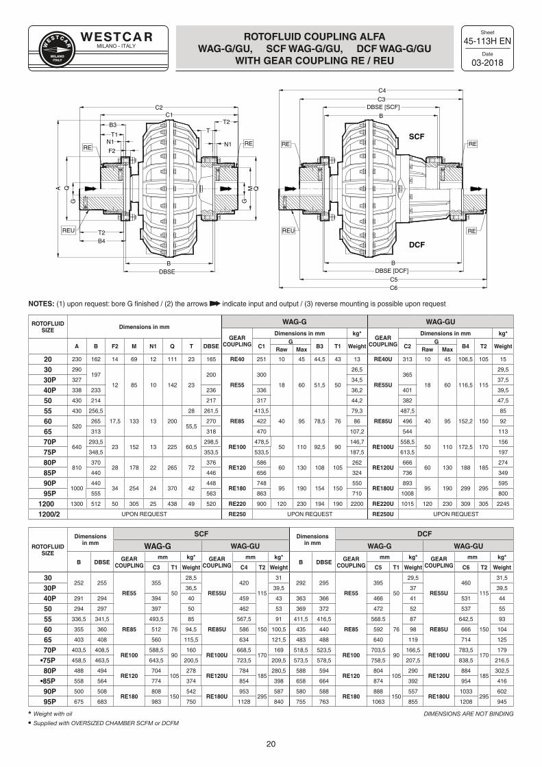
ROTOFLUID COUPLING ALFA WAG-G/GU, SCF WAG-G/GU, DCF WAG-G/GU
WITH GEAR COUPLING RE / REU
NOTES: (1) upon request: bore G finished / (2) the arrows indicate input and output / (3) reverse mounting is possible upon request
C3
C4
DBSE [SCF]
DBSE [DCF]
C5
B
C6
BDBSE
C2C1
T2
M Q
G
A QG
T2B4
B
T
N1
T1
B3
F2
N1RE
REU
RE RE
REU RE
RESCF
DCF
ROTOFLUIDSIZE Dimensions in mm
WAG-G WAG-GU
GEAR COUPLING
Dimensions in mm kg*GEAR
COUPLING
Dimensions in mm kg*
A B F2 M N1 Q T DBSE C1G
B3 T1 Weight C2G
B4 T2 WeightRaw Max Raw Max
20 230 162 14 69 12 111 23 165 RE40 251 10 45 44,5 43 13 RE40U 313 10 45 106,5 105 15
30 290197
12 85 10 142 23
200
RE55
300
18 60 51,5 50
26,5
RE55U
365
18 60 116,5 115
29,5
30P 327 34,5 37,5
40P 338 233 236 336 36,2 401 39,5
50 430 214 217 317 44,2 382 47,5
55 430 256,5
17,5 133 13 200
28 261,5
RE85
413,5
40 95 78,5 76
79,3
RE85U
487,5
40 95 152,2 150
85
60520
26555,5
270 422 86 496 92
65 313 318 470 107,2 544 113
70P640
293,523 152 13 225 60,5
298,5RE100
478,550 110 92,5 90
146,7RE100U
558,550 110 172,5 170
156
75P 348,5 353,5 533,5 187,5 613,5 197
80P810
37028 178 22 265 72
376RE120
58660 130 108 105
262RE120U
66660 130 188 185
274
85P 440 446 656 324 736 349
90P1000
44034 254 24 370 42
448RE180
74895 190 154 150
550RE180U
89395 190 299 295
595
95P 555 563 863 710 1008 800
1200 1300 512 50 305 25 438 49 520 RE220 900 120 230 194 190 2200 RE220U 1015 120 230 309 305 2245
1200/2 UPON REQUEST RE250 UPON REQUEST RE250U UPON REQUEST
30252 255
RE55
355
50
28,5
RE55U
420
115
31292 295
RE55
395
50
29,5
RE55U
460
115
31,5
30P 36,5 39,5 37 39,5
40P 291 294 394 40 459 43 363 366 466 41 531 44
50 294 297 397 50 462 53 369 372 472 52 537 55
55 336,5 341,5
RE85
493,5
76
85
RE85U
567,5
150
91 411,5 416,5
RE85
568.5
76
87
RE85U
642,5
150
93
60 355 360 512 94,5 586 100,5 435 440 592 98 666 104
65 403 408 560 115,5 634 121,5 483 488 640 119 714 125
70P 403,5 408,5RE100
588,590
160RE100U
668,5170
169 518,5 523,5RE100
703,590
166,5RE100U
783,5170
179
•75P 458,5 463,5 643,5 200,5 723,5 209,5 573,5 578,5 758,5 207,5 838,5 216,5
80P 488 494RE120
704105
278RE120U
784185
280,5 588 594RE120
804105
290RE120U
884185
302,5
•85P 558 564 774 374 854 398 658 664 874 392 954 416
90P 500 508RE180
808150
542RE180U
953295
587 580 588RE180
888150
557RE180U
1033295
602
95P 675 683 983 750 1128 840 755 763 1063 855 1208 945
Weight with oil DIMENSIONS ARE NOT BINDING Supplied with OVERSIZED CHAMBER SCFM or DCFM
ROTOFLUIDSIZE
Dimensionsin mm
SCF Dimensionsin mm
DCF
WAG-G WAG-GU WAG-G WAG-GU
B DBSE GEAR COUPLING
mm kg* GEAR COUPLING
mm kg*B DBSE GEAR
COUPLINGmm kg* GEAR
COUPLINGmm kg*
C3 T1 Weight C4 T2 Weight C5 T1 Weight C6 T2 Weight
MILANO - ITALY
Sheet
Date
21
45-120B EN
03-2018
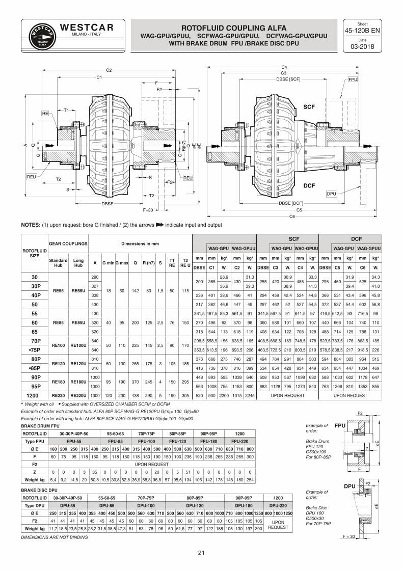
ROTOFLUID COUPLING ALFAWAG- GPU/GPUU, SCFWAG- GPU/GPUU , DCFWAG- GPU/GPUU
WITH BRAKE DRUM FPU /BRAKE DISC DPU
ROTOFLUID SIZE
GEAR COUPLINGS Dimensions in mmSCF DCF
WAG-GPU WAG-GPUU WAG-GPU WAG-GPUU WAG-GPU WAG-GPUU
Standard Hub
LongHub A G min G max Q R (h7) S T1
RET2
RE U
mm mm kg* mm kg* mm mm kg* mm kg* mm mm kg* mm kg*
DBSE C1 W. C2 W. DBSE C3 W. C4 W. DBSE C5 W. C6 W.
30
RE55 RE55U
290
18 60 142 80 1,5 50 115
200 36528,9
43031,3
255 42030,9
48533,3
295 46031,9
52534,3
30P 327 36,9 39,3 38,9 41,3 39,4 41,8
40P 338 236 401 38,6 466 41 294 459 42,4 524 44,8 366 531 43,4 596 45,8
50 430 217 382 46,6 447 49 297 462 52 527 54,5 372 537 54,4 602 56,8
55
RE85 RE85U
430
40 95 200 125 2,5 76 150
261,5 487,5 85,3 561,5 91 341,5 567,5 91 641.5 97 416,5 642,5 93 716,5 99
60 520 270 496 92 570 98 360 586 101 660 107 440 666 104 740 110
65 520 318 544 113 618 119 408 634 122 708 128 488 714 125 788 131
70PRE100 RE100U
64050 110 225 145 2,5 90 170
298,5 558,5 156 638,5 165 408,5 668,5 169 748,5 178 523,5 783,5 176 863,5 185
•75P 640 353,5 613,5 196 693,5 206 463,5 723,5 210 803,5 219 578,5 838,5 217 918,5 226
80PRE120 RE120U
81060 130 265 175 3 105 185
376 666 275 746 287 494 784 291 864 303 594 884 303 964 315
•85P 810 416 736 378 816 399 534 854 428 934 449 634 954 447 1034 469
90PRE180 RE180U
100095 190 370 245 4 150 295
448 893 595 1038 640 508 953 587 1098 632 588 1033 602 1178 647
95P 1000 563 1008 755 1153 800 683 1128 795 1273 840 763 1208 810 1353 855
1200 RE220 RE220U 1300 120 230 438 290 5 190 305 520 900 2200 1015 2245 UPON REQUEST UPON REQUEST
Weight with oil Supplied with OVERSIZED CHAMBER SCFM or DCFM
Example of order with standard hub: ALFA 80P SCF WAG-G RE120PU G(m)= 100 G(r)=90
Example of order with long hub: ALFA 80P SCF WAG-G RE120PUU G(m)= 100 G(r)=90
BRAKE DRUM FPU
ROTOFLUID 30-30P-40P-50 55-60-65 70P-75P 80P-85P 90P-95P 1200
Type FPU FPU-55 FPU-85 FPU-100 FPU-120 FPU-180 FPU-220
Ø E 160 200 250 315 400 250 315 400 315 400 500 400 500 630 500 630 710 630 710 800
F 60 75 95 118 150 95 118 150 118 150 190 150 190 236 190 236 265 236 265 300
F2 UPON REQUEST
Z 0 0 0 3 35 0 0 0 0 0 20 0 5 51 0 0 0 0 0 0
Weight kg 5,4 9,2 14,5 29 50,8 19,5 30,8 52,8 35,9 58,3 96,8 57 95,6 134 105 142 178 145 180 254
BRAKE DISC DPU
ROTOFLUID 30-30P-40P-50 55-60-65 70P-75P 80P-85P 90P-95P 1200
Type DPU DPU-55 DPU-85 DPU-100 DPU-120 DPU-180 DPU-220
Ø E 250 315 355 400 355 400 450 500 500 560 630 710 500 560 630 710 800 1000 710 800 1000 1250 800 1000 1250
F2 41 41 41 41 45 45 45 45 60 60 60 60 60 60 60 60 60 60 105 105 105 105 UPON REQUESTWeight kg 11,7 18,5 23,5 28,8 25,2 31,5 38,5 47,3 51 63 78 98 50 61,6 77 97 122 188 105 130 197 300
DIMENSIONS ARE NOT BINDING
NOTES: (1) upon request: bore G finished / (2) the arrows indicate input and output
Example of order:
Brake DrumFPU 120 Ø500x190For 80P-85P
Example of order:
Brake Disc DPU 100 Ø500x30For 70P-75P
C3C4
DBSE [SCF]
C5
C6
DBSE [DCF]
S
DBSE
C2
C1F
øE
øEQ
G
T2S
T2
A QG
T1
F2
REU REU
FPU
DPU
SCF
DCF
RE
F2
F=30
R(h
7)
FPU
F2
F2
Z
F
F = 30
øE
øE
DPU
MILANO - ITALY
Sheet
Date
22
45-300F EN
03-2018
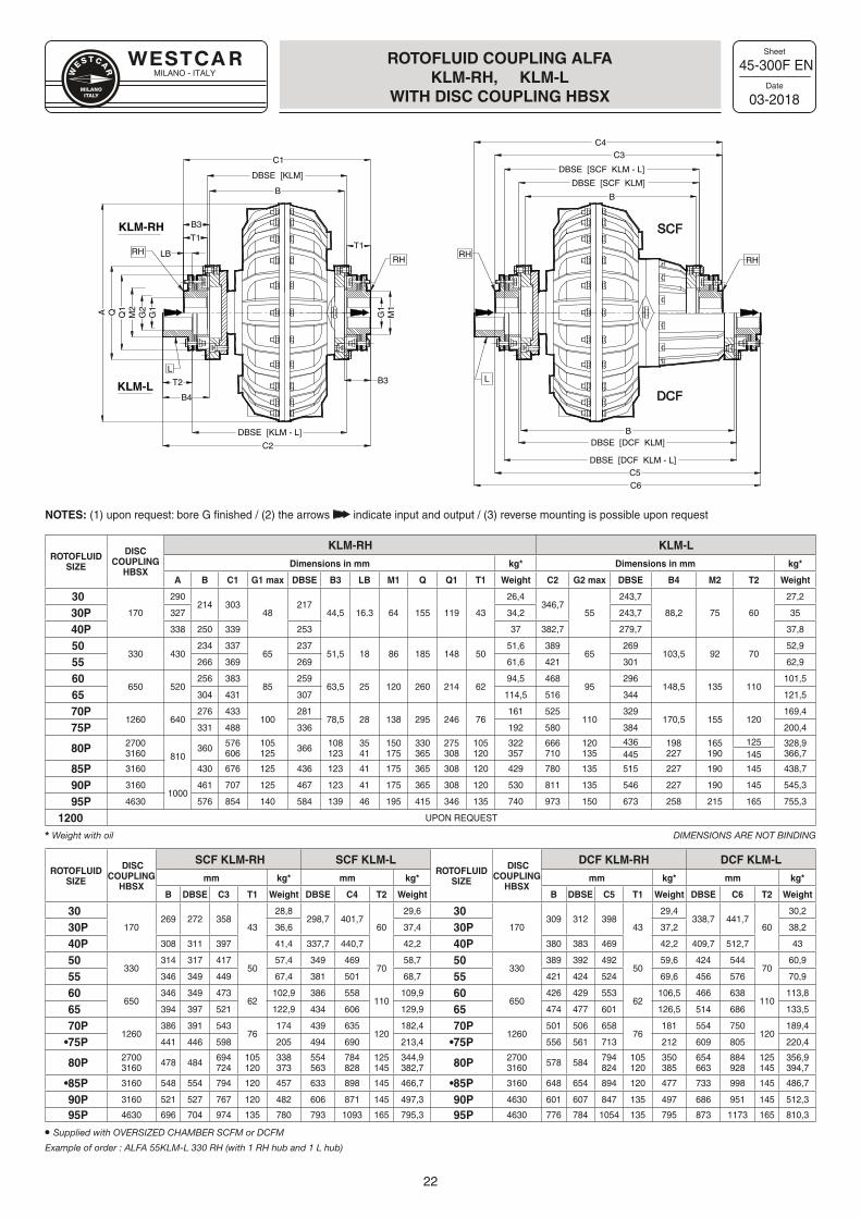
ROTOFLUID COUPLING ALFA KLM-RH, KLM-L
WITH DISC COUPLING HBSX
ROTOFLUID SIZE
DISC COUPLING
HBSX
KLM-RH KLM-L
Dimensions in mm kg* Dimensions in mm kg*
A B C1 G1 max DBSE B3 LB M1 Q Q1 T1 Weight C2 G2 max DBSE B4 M2 T2 Weight
30170
290214 303
48217
44,5 16.3 64 155 119 43
26,4346,7
55
243,7
88,2 75 60
27,2
30P 327 34,2 243,7 35
40P 338 250 339 253 37 382,7 279,7 37,8
50330 430
234 33765
23751,5 18 86 185 148 50
51,6 38965
269103,5 92 70
52,9
55 266 369 269 61,6 421 301 62,9
60650 520
256 38385
25963,5 25 120 260 214 62
94,5 46895
296148,5 135 110
101,5
65 304 431 307 114,5 516 344 121,5
70P1260 640
276 433100
28178,5 28 138 295 246 76
161 525110
329170,5 155 120
169,4
75P 331 488 336 192 580 384 200,4
80P 27003160 810
360 576606
105125 366 108
1233541
150175
330365
275308
105120
322357
666710
120135
436 198227
165190
125 328,9366,7445 145
85P 3160 430 676 125 436 123 41 175 365 308 120 429 780 135 515 227 190 145 438,7
90P 31601000
461 707 125 467 123 41 175 365 308 120 530 811 135 546 227 190 145 545,3
95P 4630 576 854 140 584 139 46 195 415 346 135 740 973 150 673 258 215 165 755,3
1200 UPON REQUEST
Weight with oil DIMENSIONS ARE NOT BINDING
ROTOFLUIDSIZE
DISC COUPLING
HBSX
SCF KLM-RH SCF KLM-LROTOFLUID
SIZE
DISC COUPLING
HBSX
DCF KLM-RH DCF KLM-L
mm kg* mm kg* mm kg* mm kg*
B DBSE C3 T1 Weight DBSE C4 T2 Weight B DBSE C5 T1 Weight DBSE C6 T2 Weight
30 170
269 272 35843
28,8298,7 401,7
60
29,6 30 170
309 312 39843
29,4338,7 441,7
60
30,2
30P 36,6 37,4 30P 37,2 38,2
40P 308 311 397 41,4 337,7 440,7 42,2 40P 380 383 469 42,2 409,7 512,7 43
50 330
314 317 41750
57,4 349 46970
58,7 50 330
389 392 49250
59,6 424 54470
60,9
55 346 349 449 67,4 381 501 68,7 55 421 424 524 69,6 456 576 70,9
60 650
346 349 47362
102,9 386 558110
109,9 60 650
426 429 55362
106,5 466 638110
113,8
65 394 397 521 122,9 434 606 129,9 65 474 477 601 126,5 514 686 133,5
70P 1260
386 391 54376
174 439 635120
182,4 70P 1260
501 506 65876
181 554 750120
189,4
•75P 441 446 598 205 494 690 213,4 •75P 556 561 713 212 609 805 220,4
80P 27003160 478 484 694
724105120
338373
554563
784828
125145
344,9382,7 80P 2700
3160 578 584 794824
105120
350385
654663
884928
125145
356,9394,7
•85P 3160 548 554 794 120 457 633 898 145 466,7 •85P 3160 648 654 894 120 477 733 998 145 486,7
90P 3160 521 527 767 120 482 606 871 145 497,3 90P 4630 601 607 847 135 497 686 951 145 512,3
95P 4630 696 704 974 135 780 793 1093 165 795,3 95P 4630 776 784 1054 135 795 873 1173 165 810,3
Supplied with OVERSIZED CHAMBER SCFM or DCFM
Example of order : ALFA 55KLM-L 330 RH (with 1 RH hub and 1 L hub)
NOTES: (1) upon request: bore G finished / (2) the arrows indicate input and output / (3) reverse mounting is possible upon request
RHRH
RH
KLM-RH
KLM-L
C1
B
B3
T1
LB
A Q Q1
M2
G2
G1
B3T2
T1
G1
M1
B4
DBSE [KLM - L]
C2
RH
L
C3C4
DBSE [SCF KLM]
DBSE [SCF KLM - L]
B
C5
C6
DBSE [DCF KLM]
DBSE [DCF KLM - L]
B
SCF
DCF
L
DBSE [KLM]
MILANO - ITALY
Sheet
Date
23
45-305D EN
03-2018
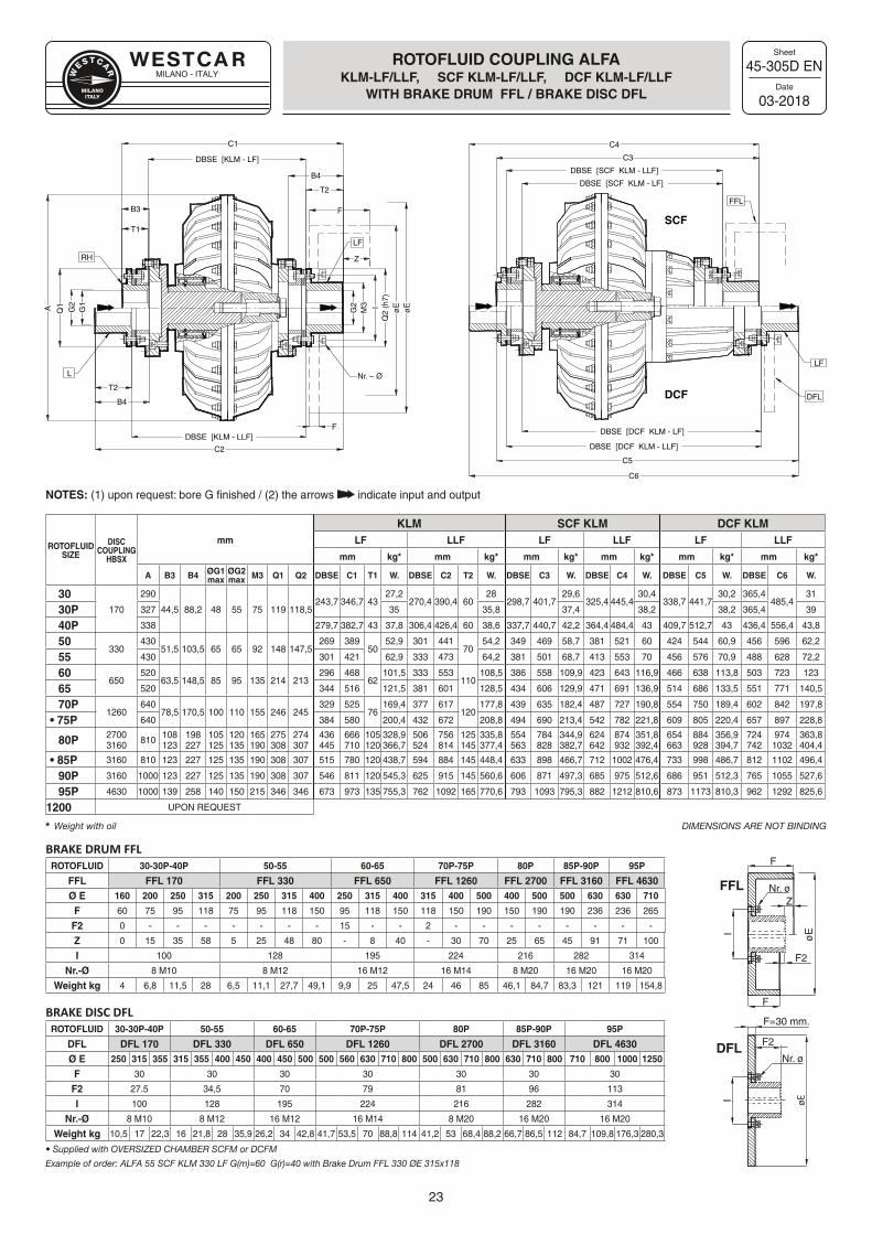
ROTOFLUID COUPLING ALFAKLM-LF/LLF, SCF KLM-LF/LLF, DCF KLM-LF/LLF
WITH BRAKE DRUM FFL / BRAKE DISC DFL
BRAKE DRUM FFLROTOFLUID 30-30P-40P 50-55 60-65 70P-75P 80P 85P-90P 95P
FFL FFL 170 FFL 330 FFL 650 FFL 1260 FFL 2700 FFL 3160 FFL 4630Ø E 160 200 250 315 200 250 315 400 250 315 400 315 400 500 400 500 500 630 630 710
F 60 75 95 118 75 95 118 150 95 118 150 118 150 190 150 190 190 236 236 265
F2 0 - - - - - - - 15 - - 2 - - - - - - - -
Z 0 15 35 58 5 25 48 80 - 8 40 - 30 70 25 65 45 91 71 100
I 100 128 195 224 216 282 314
Nr.-Ø 8 M10 8 M12 16 M12 16 M14 8 M20 16 M20 16 M20
Weight kg 4 6,8 11,5 28 6,5 11,1 27,7 49,1 9,9 25 47,5 24 46 85 46,1 84,7 83,3 121 119 154,8
BRAKE DISC DFLROTOFLUID 30-30P-40P 50-55 60-65 70P-75P 80P 85P-90P 95P
DFL DFL 170 DFL 330 DFL 650 DFL 1260 DFL 2700 DFL 3160 DFL 4630Ø E 250 315 355 315 355 400 450 400 450 500 500 560 630 710 800 500 630 710 800 630 710 800 710 800 1000 1250
F 30 30 30 30 30 30 30
F2 27.5 34,5 70 79 81 96 113
I 100 128 195 224 216 282 314
Nr.-Ø 8 M10 8 M12 16 M12 16 M14 8 M20 16 M20 16 M20
Weight kg 10,5 17 22,3 16 21,8 28 35,9 26,2 34 42,8 41,7 53,5 70 88,8 114 41,2 53 68,4 88,2 66,7 86,5 112 84,7 109,8 176,3 280,3
• Supplied with OVERSIZED CHAMBER SCFM or DCFM
Example of order: ALFA 55 SCF KLM 330 LF G(m)=60 G(r)=40 with Brake Drum FFL 330 ØE 315x118
NOTES: (1) upon request: bore G finished / (2) the arrows indicate input and output
ROTOFLUID SIZE
DISC COUPLING
HBSX
mm
KLM SCF KLM DCF KLMLF LLF LF LLF LF LLF
mm kg* mm kg* mm kg* mm kg* mm kg* mm kg*
A B3 B4 ØG1 max
ØG2 max M3 Q1 Q2 DBSE C1 T1 W. DBSE C2 T2 W. DBSE C3 W. DBSE C4 W. DBSE C5 W. DBSE C6 W.
30170
290
44,5 88,2 48 55 75 119 118,5243,7 346,7 43
27,2270,4 390,4 60
28298,7 401,7
29,6325,4 445,4
30,4338,7 441,7
30,2 365,4485,4
31
30P 327 35 35,8 37,4 38,2 38,2 365,4 39
40P 338 279,7 382,7 43 37,8 306,4 426,4 60 38,6 337,7 440,7 42,2 364,4 484,4 43 409,7 512,7 43 436,4 556,4 43,8
50330
43051,5 103,5 65 65 92 148 147,5
269 38950
52,9 301 44170
54,2 349 469 58,7 381 521 60 424 544 60,9 456 596 62,2
55 430 301 421 62,9 333 473 64,2 381 501 68,7 413 553 70 456 576 70,9 488 628 72,2
60650
52063,5 148,5 85 95 135 214 213
296 46862
101,5 333 553110
108,5 386 558 109,9 423 643 116,9 466 638 113,8 503 723 123
65 520 344 516 121,5 381 601 128,5 434 606 129,9 471 691 136,9 514 686 133,5 551 771 140,5
70P1260
64078,5 170,5 100 110 155 246 245
329 52576
169,4 377 617120
177,8 439 635 182,4 487 727 190,8 554 750 189,4 602 842 197,8
• 75P 640 384 580 200,4 432 672 208,8 494 690 213,4 542 782 221,8 609 805 220,4 657 897 228,8
80P 27003160 810 108
123198227
105125
120135
165190
275308
274307
436445
666710
105120
328,9366,7
506524
756814
125145
335,8377,4
554563
784828
344,9382,7
624642
874932
351,8392,4
654663
884928
356,9394,7
724742
9741032
363,8404,4
• 85P 3160 810 123 227 125 135 190 308 307 515 780 120 438,7 594 884 145 448,4 633 898 466,7 712 1002 476,4 733 998 486,7 812 1102 496,4
90P 3160 1000 123 227 125 135 190 308 307 546 811 120 545,3 625 915 145 560,6 606 871 497,3 685 975 512,6 686 951 512,3 765 1055 527,6
95P 4630 1000 139 258 140 150 215 346 346 673 973 135 755,3 762 1092 165 770,6 793 1093 795,3 882 1212 810,6 873 1173 810,3 962 1292 825,6
1200 UPON REQUEST
Weight with oil DIMENSIONS ARE NOT BINDING
DBSE [SCF KLM - LF]
DBSE [SCF KLM - LLF]
DBSE [DCF KLM - LF]
DBSE [DCF KLM - LLF]
DBSE [KLM - LF]
B3
C1
G2
F
T2
Z
Q1
M3
G1
A G2 I
Q2
(h7)
øE
øE
T1
Nr. – Ø
T2
F
FFL
LF
DFL
LF
C5
C6
C4
C3
DBSE [KLM - LLF]
C2
B4
L
B4
RH
SCF
DCF
F
F
Nr. ø
øE
Nr. ø
øE
F=30 mm.
F2
F2
FFLZ
I
DFL
I
MILANO - ITALY
Sheet
Date
24
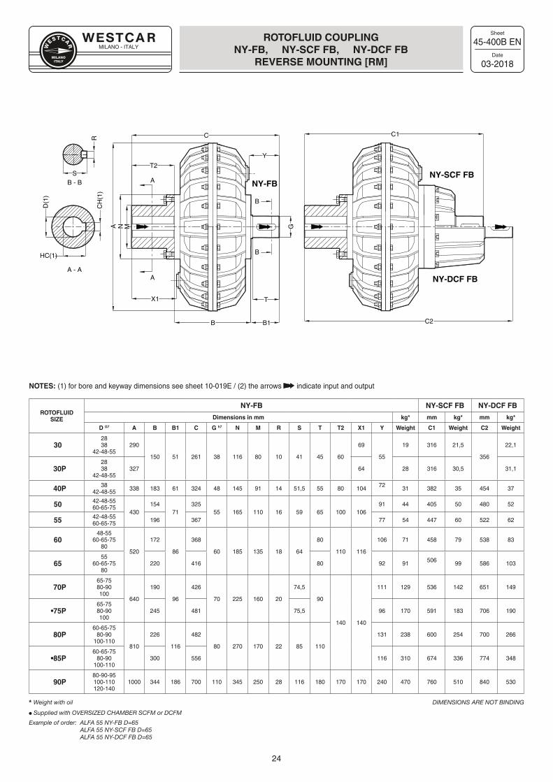
ROTOFLUIDSIZE
NY-FB NY-SCF FB NY-DCF FB
Dimensions in mm kg* mm kg* mm kg*
D G7 A B B1 C G h7 N M R S T T2 X1 Y Weight C1 Weight C2 Weight
302838
42-48-55290
150 51 261 38 116 80 10 41 45 60
69
55
19 316 21,5
356
22,1
30P2838
42-48-55327 64 28 316 30,5 31,1
40P 3842-48-55 338 183 61 324 48 145 91 14 51,5 55 80 104 72 31 382 35 454 37
50 42-48-5560-65-75
430154
71325
55 165 110 16 59 65 100 10691 44 405 50 480 52
55 42-48-5560-65-75 196 367 77 54 447 60 522 62
6048-55
60-65-7580
520
172
86
368
60 185 135 18 64
80
110 116
106 71 458 79 538 83
6555
60-65-7580
220 416 80 92 91 506 99 586 103
70P65-7580-90100
640
190
96
426
70 225 160 20
74,5
90
140 140
111 129 536 142 651 149
•75P65-7580-90100
245 481 75,5 96 170 591 183 706 190
80P 60-65-75
80-90100-110
810
226
116
482
80 270 170 22 85 110
131 238 600 254 700 266
•85P60-65-75
80-90100-110
300 556 116 310 674 336 774 348
90P80-90-95100-110120-140
1000 344 186 700 110 345 250 28 116 180 170 170 240 470 760 510 840 530
Weight with oil DIMENSIONS ARE NOT BINDING
Supplied with OVERSIZED CHAMBER SCFM or DCFM
Example of order: ALFA 55 NY-FB D=65 ALFA 55 NY-SCF FB D=65 ALFA 55 NY-DCF FB D=65
45-400B EN
03-2018
ROTOFLUID COUPLING NY-FB, NY-SCF FB, NY-DCF FB
REVERSE MOUNTING [RM]
NOTES: (1) for bore and keyway dimensions see sheet 10-019E / (2) the arrows indicate input and output
NY-FBNY-SCF FB
NY-DCF FBA
A
A
C C1
C2
HC(1)
S
R
A - A
B - B
D(1
)
CH
(1)
MN
B B1
T
G
T2
X1
Y
B
B
MILANO - ITALY
Sheet
Date
25
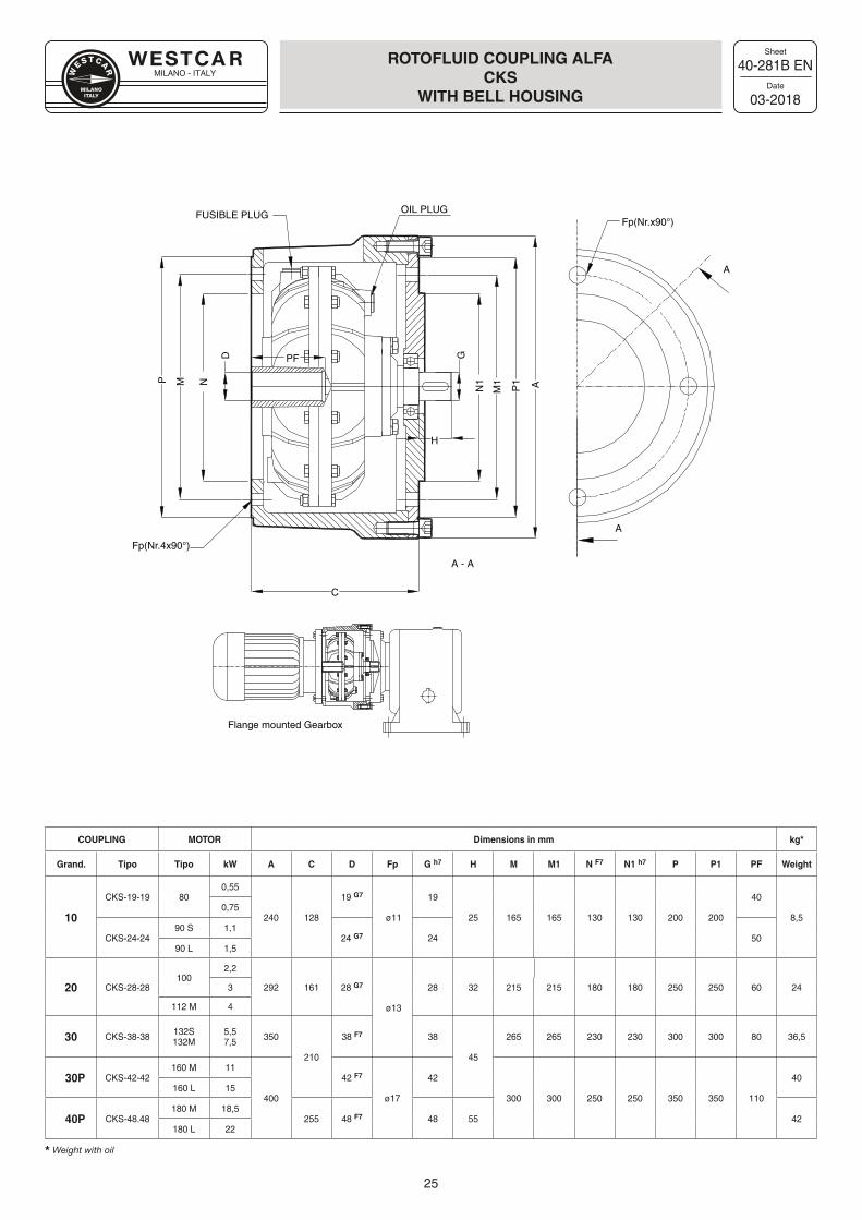
40-281B EN
03-2018
ROTOFLUID COUPLING ALFA CKS
WITH BELL HOUSING
Flange mounted Gearbox
M N
M1
N1 AP
P1
GPF
A
A
Fp(Nr.x90°)OIL PLUG
H
C
Fp(Nr.4x90°)
A - A
FUSIBLE PLUGD
COUPLING MOTOR Dimensions in mm kg*
Grand. Tipo Tipo kW A C D Fp G h7 H M M1 N F7 N1 h7 P P1 PF Weight
10
CKS-19-19 800,55
240 128
19 G7
ø11
19
25 165 165 130 130 200 200
40
8,50,75
CKS-24-2490 S 1,1
24 G7 24 5090 L 1,5
20 CKS-28-28100
2,2
292 161 28 G7
ø13
28 32 215 215 180 180 250 250 60 243
112 M 4
30 CKS-38-38 132S132M
5,57,5 350
210
38 F7 38
45
265 265 230 230 300 300 80 36,5
30P CKS-42-42160 M 11
400
42 F7
ø17
42
300 300 250 250 350 350 110
40160 L 15
40P CKS-48.48180 M 18,5
255 48 F7 48 55 42180 L 22
Weight with oil
MILANO - ITALY
Sheet
Date
26
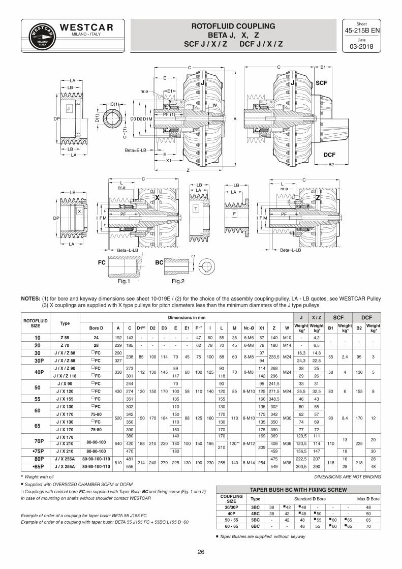
45-215B EN
03-2018
ROTOFLUID COUPLING BETA J, X, Z
SCF J / X / Z DCF J / X / Z
NOTES: (1) for bore and keyway dimensions see sheet 10-019E / (2) for the choice of the assembly coupling-pulley, LA - LB quotes, see WESTCAR Pulley (3) X couplings are supplied with X type pulleys for pitch diameters less than the minimum diameters of the J type pulleys
ROTOFLUIDSIZE Type
Dimensions in mm J X / Z SCF DCF
Bore D A C D1H7 D2 D3 E E1 F H7 I L M Nr.-Ø X1 Z W Weight kg*
Weight kg* B1 Weight
kg* B2 Weight kg*
10 Z 55 24 192 143 - - - - - 47 60 55 35 6-M6 57 140 M10 - 4,2- - - -
20 Z 70 28 229 185 - - - - - 62 78 70 45 6-M8 76 180 M14 - 6,5
30 J / X / Z 88 �FC 290238 85 100 114 70 45 75 100 88 60 8-M8
97233,5 M24
16,3 14,855 2,4 95 3
30P J / X / Z 88 �FC 327 94 24,3 22,8
40PJ / X / Z 90 �FC
338273
112 130 14589
60 100 12590
70 8-M8114 268
M2428 25
58 4 130 5J / X / Z 118 �FC 301 117 118 142 296 29 26
50J / X 90 �FC
430
244
130 150 170
70
58 110 140
90
85 8-M10
95 241,5
M24
33 31
80 6 155 8J / X 120 �FC 274 100 120 125 271,5 35,5 32,5
55 J / X 155 �FC 351 135 155 160 348,5 46 43
60J / X 130 �FC
520
302
150 170 184
110
88 125 160
130
110 8-M10
135 302
M30
60 55
90 8,4 170 12J / X 170 75-80 342 150 170 175 342 62 57
65J / X 130 �FC 350 110 130 135 350 74 69
J / X 170 75-80 390 150 170 175 390 77 72
70PJ / X 170
80-90-100 640
380
188 210 230
140
100 150 195
170
120** 8-M12
169 369
M36
120,5 111
11013
22520
J / X 210 420 180210 209
409 123,5 114
•75P J / X 210 80-90-100 470 180 459 156,5 147 18 30
80P J / X 255A 80-90-100-110810
481214 240 270 225 130 190 230 255 140 8-M14 254
475M36
222,5 207118
16218
28
•85P J / X 255A 80-90-100-110 555 549 303,5 290 28 48
Weight with oil DIMENSIONS ARE NOT BINDING
Supplied with OVERSIZED CHAMBER SCFM or DCFM
Couplings with conical bore FC are supplied with Taper Bush BC and fixing screw (Fig. 1 and 2)
In case of mounting on shafts without shoulder contact WESTCAR
Example of order of a coupling for taper bush: BETA 55 J155 FCExample of order of a coupling with taper bush: BETA 55 J155 FC + 55BC L155 D=60
TAPER BUSH BC WITH FIXING SCREWCOUPLING
SIZE Type Standard D Bore Max D Bore
30/30P 3BC 38 42 48 - - - 4840P 4BC 38 42 48 50 - - 50
50 - 55 5BC - 42 48 55 60 65 6560 - 65 6BC - - 48 55 60 65 70
Taper Bushes are supplied without keyway
nr.ø E1
C
A
Beta=E-LBE
X1
D3PF (1)
D1D2 M
E
C
HC(1)
D(1
)
CH
(1)
LA
DP
LALB
I M
CL
F
nr.øLB
DPPF
FIPF
nr.øL
B1
B2
SCF
DCF
LB LB
X TF
M
Beta=L-LB
C
Beta=L-LB
LA LA
J
LB
Z
W
LA
FC BC
D
Fig.1 Fig.2
J J
ZX
MILANO - ITALY
Sheet
Date
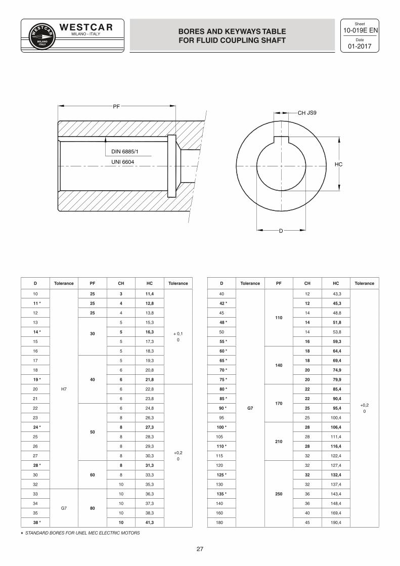
27
10-019E EN
01-2017
BORES AND KEYWAYS TABLEFOR FLUID COUPLING SHAFT
D Tolerance PF CH HC Tolerance D Tolerance PF CH HC Tolerance
10 25 3 11,4
+ 0,10
40
G7
110
12 43,3
+0,20
11 * 25 4 12,8 42 * 12 45,3
12 25 4 13,8 45 14 48,8
13
30
5 15,3 48 * 14 51,8
14 * 5 16,3 50 14 53,8
15 5 17,3 55 * 16 59,3
16 5 18,3 60 *
140
18 64,4
17
40
5 19,3 65 * 18 69,4
18 6 20,8 70 * 20 74,9
19 * 6 21,8 75 * 20 79,9
20 H7 6 22,8
+0,20
80 *
170
22 85,4
21 6 23,8 85 * 22 90,4
22
50
6 24,8 90 * 25 95,4
23 8 26,3 95 25 100,4
24 * 8 27,3 100 *
210
28 106,4
25 8 28,3 105 28 111,4
26 8 29,3 110 * 28 116,4
27 8 30,3 115 32 122,4
28 *
60
8 31,3 120
250
32 127,4
30 8 33,3 125 * 32 132,4
32 10 35,3 130 32 137,4
33
G7 80
10 36,3 135 * 36 143,4
34 10 37,3 140 36 148,4
35 10 38,3 160 40 169,4
38 * 10 41,3 180 45 190,4
STANDARD BORES FOR UNEL MEC ELECTRIC MOTORS
DIN 6885/1
CH
D
HC
JS9PF
UNI 6604
MILANO - ITALY
Sheet
Date
28
80-035 EN
01-2017
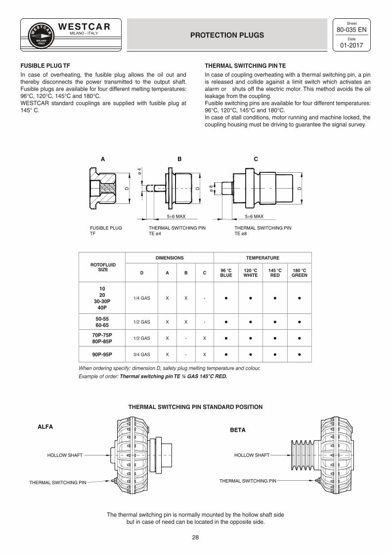
PROTECTION PLUGS
ROTOFLUID SIZE
DIMENSIONS TEMPERATURE
D A B C 96 °CBLUE
120 °CWHITE
145 °CRED
180 °CGREEN
1020
30-30P40P
1/4 GAS X X - • • • •
50-5560-65
1/2 GAS X X - • • • •
70P-75P80P-85P
1/2 GAS X - X • • • •
90P-95P 3/4 GAS X - X • • • •
FUSIBLE PLUGTF
THERMAL SWITCHING PIN TE ø4
THERMAL SWITCHING PIN TE ø8
Dø 8DD
A B C
5÷6 MAX 5÷6 MAX
ø 4
ALFA
THERMAL SWITCHING PIN
HOLLOW SHAFT
BETA
THERMAL SWITCHING PIN
HOLLOW SHAFT
FUSIBLE PLUG TF
In case of overheating, the fusible plug allows the oil out and thereby disconnects the power transmitted to the output shaft. Fusible plugs are available for four different melting temperatures: 96°C, 120°C, 145°C and 180°C.WESTCAR standard couplings are supplied with fusible plug at 145° C.
THERMAL SWITCHING PIN TE
In case of coupling overheating with a thermal switching pin, a pin is released and collide against a limit switch which activates an alarm or shuts off the electric motor. This method avoids the oil leakage from the coupling.Fusible switching pins are available for four different temperatures: 96°C, 120°C, 145°C and 180°C.In case of stall conditions, motor running and machine locked, the coupling housing must be driving to guarantee the signal survey.
When ordering specify: dimension D, safety plug melting temperature and colour.
Example of order: Thermal switching pin TE ¼ GAS 145°C RED.
THERMAL SWITCHING PIN STANDARD POSITION
The thermal switching pin is normally mounted by the hollow shaft sidebut in case of need can be located in the opposite side.
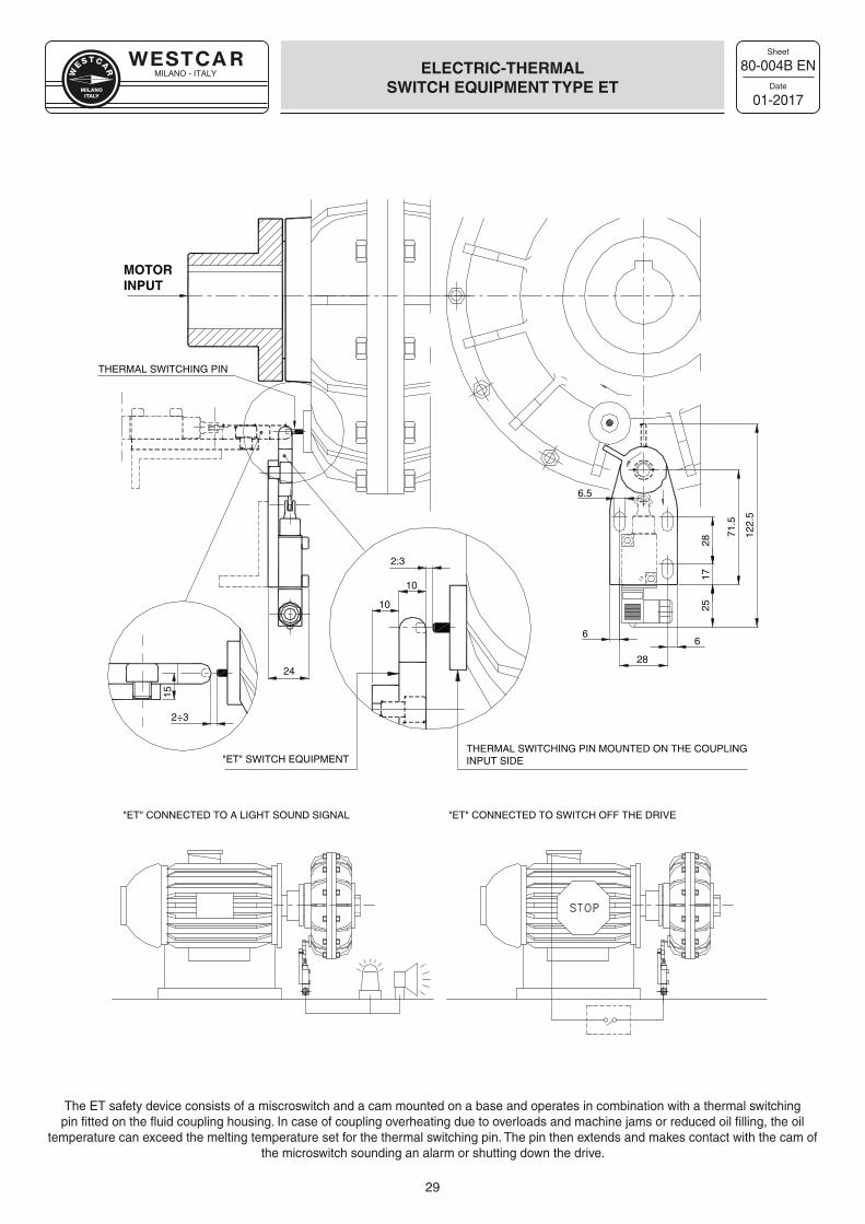
MILANO - ITALY
Sheet
Date
29
80-004B EN
01-2017
ELECTRIC-THERMALSWITCH EQUIPMENT TYPE ET
The ET safety device consists of a miscroswitch and a cam mounted on a base and operates in combination with a thermal switching pin fitted on the fluid coupling housing. In case of coupling overheating due to overloads and machine jams or reduced oil filling, the oil
temperature can exceed the melting temperature set for the thermal switching pin. The pin then extends and makes contact with the cam of the microswitch sounding an alarm or shutting down the drive.
THERMAL SWITCHING PIN MOUNTED ON THE COUPLINGINPUT SIDE
15
"ET" CONNECTED TO A LIGHT SOUND SIGNAL
2÷3
"ET" SWITCH EQUIPMENT
10
10
2:3
28
71.5
17
66
25
6.5
2428
THERMAL SWITCHING PIN
122.
5
"ET" CONNECTED TO SWITCH OFF THE DRIVE
MOTORINPUT
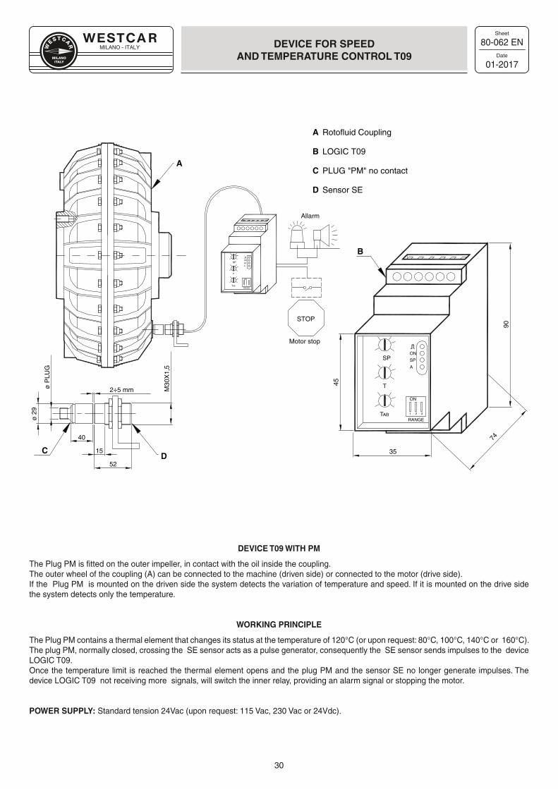
MILANO - ITALY
Sheet
Date
30
80-062 EN
01-2017
DEVICE FOR SPEEDAND TEMPERATURE CONTROL T09
DEVICE T09 WITH PM
The Plug PM is fitted on the outer impeller, in contact with the oil inside the coupling.The outer wheel of the coupling (A) can be connected to the machine (driven side) or connected to the motor (drive side).If the Plug PM is mounted on the driven side the system detects the variation of temperature and speed. If it is mounted on the drive side the system detects only the temperature.
WORKING PRINCIPLE
The Plug PM contains a thermal element that changes its status at the temperature of 120°C (or upon request: 80°C, 100°C, 140°C or 160°C).The plug PM, normally closed, crossing the SE sensor acts as a pulse generator, consequently the SE sensor sends impulses to the device LOGIC T09. Once the temperature limit is reached the thermal element opens and the plug PM and the sensor SE no longer generate impulses. The device LOGIC T09 not receiving more signals, will switch the inner relay, providing an alarm signal or stopping the motor.
POWER SUPPLY: Standard tension 24Vac (upon request: 115 Vac, 230 Vac or 24Vdc).
A
B
C
D
Rotofluid Coupling
LOGIC T09
PLUG "PM" no contact
Sensor SE
STOP
Allarm
Motor stop
1 2 3
ON
RANGETAB
T
SPON
SP
A
1 2 3
ON
RANGETAB
T
SPON
SP
A
35
52
74
90
45
15
40
ø 2
9
ø P
LUG
2÷5 mm M30
X1,
5A
B
CD
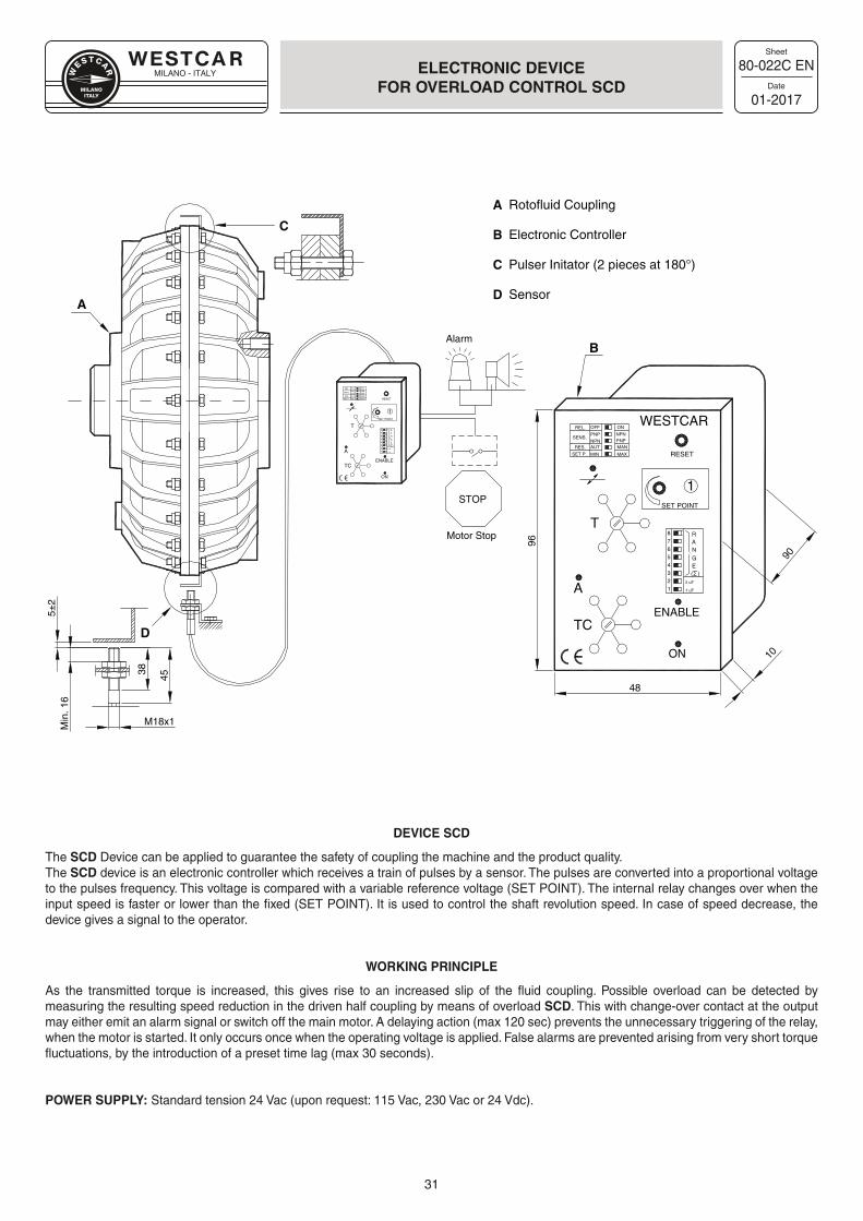
MILANO - ITALY
Sheet
Date
31
80-022C EN
01-2017
ELECTRONIC DEVICEFOR OVERLOAD CONTROL SCD
DEVICE SCD
The SCD Device can be applied to guarantee the safety of coupling the machine and the product quality.The SCD device is an electronic controller which receives a train of pulses by a sensor. The pulses are converted into a proportional voltage to the pulses frequency. This voltage is compared with a variable reference voltage (SET POINT). The internal relay changes over when the input speed is faster or lower than the fixed (SET POINT). It is used to control the shaft revolution speed. In case of speed decrease, the device gives a signal to the operator.
WORKING PRINCIPLE
As the transmitted torque is increased, this gives rise to an increased slip of the fluid coupling. Possible overload can be detected by measuring the resulting speed reduction in the driven half coupling by means of overload SCD. This with change-over contact at the output may either emit an alarm signal or switch off the main motor. A delaying action (max 120 sec) prevents the unnecessary triggering of the relay, when the motor is started. It only occurs once when the operating voltage is applied. False alarms are prevented arising from very short torque fluctuations, by the introduction of a preset time lag (max 30 seconds).
POWER SUPPLY: Standard tension 24 Vac (upon request: 115 Vac, 230 Vac or 24 Vdc).
OFF
PNPNPNAUT
MIN
ON
MAN
MAX
54
678
321 1 uF
2 uF
1SET POINT
RESET
T
TC
A
ENABLE
ON
Min
. 16
5±2
C
A
D
B
A
B
C
D
Rotofluid Coupling
Electronic Controller
Pulser Initator (2 pieces at 180°)
Sensor
M18x1
45
38
STOP
Alarm
Motor Stop
NPNPNP
REL.
SENS.
RES.
SET P.
RANGE( )
OFF
PNPNPNAUT
MIN
ON
MAN
MAX
54
678
321 1 uF
2 uF
1SET POINT
RESET
T
TC
A
ENABLE
ON
NPNPNP
REL.
SENS.
RES.
SET P.
RANGE( )
WESTCAR
96
48
10
90
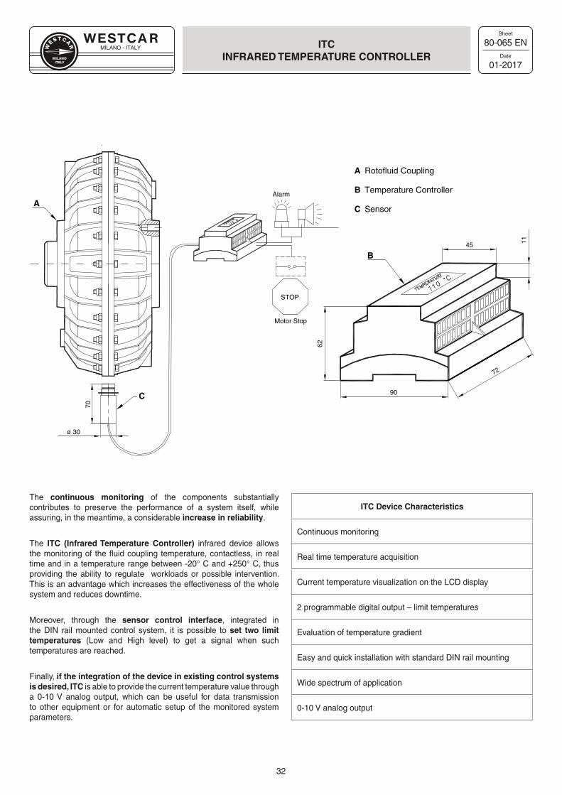
MILANO - ITALY
Sheet
Date
32
80-065 EN
01-2017
ITCINFRARED TEMPERATURE CONTROLLER
A
A
B
C
Rotofluid Coupling
Temperature Controller
Sensor
STOP
Alarm
Motor Stop
B45
90
62
11
72
ø 30
70
C
The continuous monitoring of the components substantially contributes to preserve the performance of a system itself, while assuring, in the meantime, a considerable increase in reliability.
The ITC (Infrared Temperature Controller) infrared device allows the monitoring of the fluid coupling temperature, contactless, in real time and in a temperature range between -20° C and +250° C, thus providing the ability to regulate workloads or possible intervention. This is an advantage which increases the effectiveness of the whole system and reduces downtime.
Moreover, through the sensor control interface, integrated in the DIN rail mounted control system, it is possible to set two limit temperatures (Low and High level) to get a signal when such temperatures are reached.
Finally, if the integration of the device in existing control systems is desired, ITC is able to provide the current temperature value through a 0-10 V analog output, which can be useful for data transmission to other equipment or for automatic setup of the monitored system parameters.
ITC Device Characteristics
Continuous monitoring
Real time temperature acquisition
Current temperature visualization on the LCD display
2 programmable digital output – limit temperatures
Evaluation of temperature gradient
Easy and quick installation with standard DIN rail mounting
Wide spectrum of application
0-10 V analog output
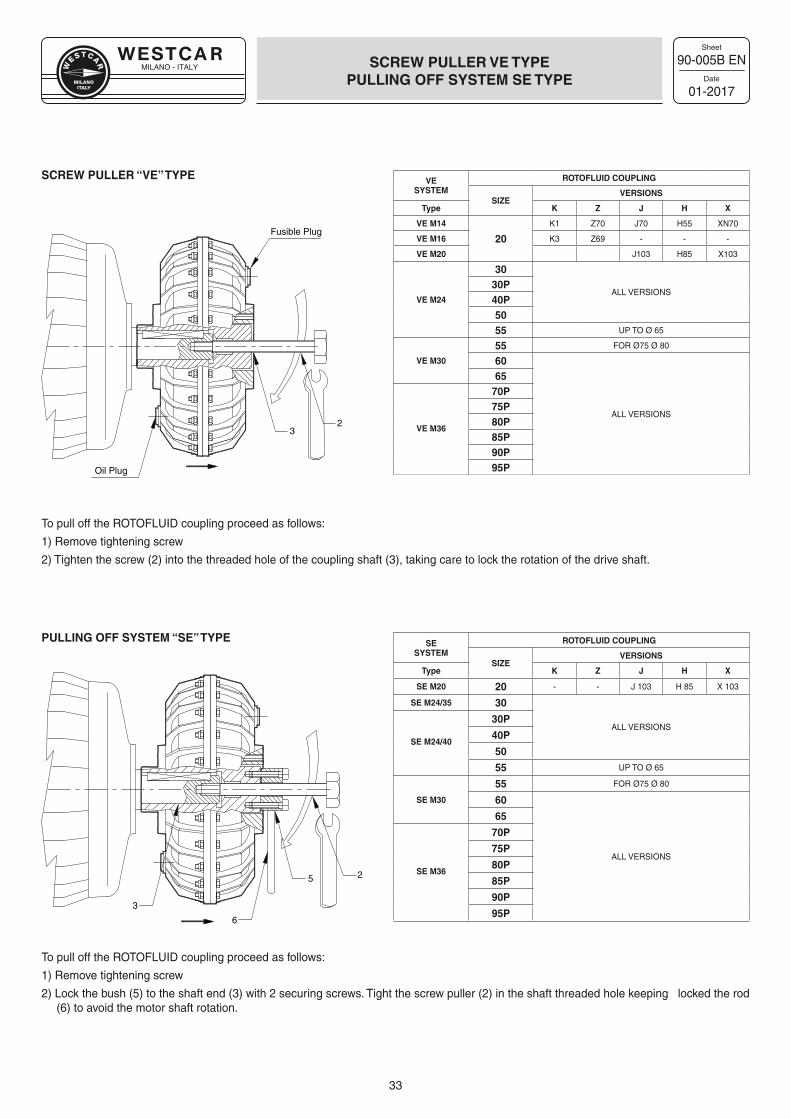
MILANO - ITALY
Sheet
Date
33
90-005B EN
01-2017
SCREW PULLER VE TYPE PULLING OFF SYSTEM SE TYPE
Oil Plug
Fusible Plug
23
3
5 2
6
SCREW PULLER “VE” TYPE
PULLING OFF SYSTEM “SE” TYPE
To pull off the ROTOFLUID coupling proceed as follows:
1) Remove tightening screw
2) Tighten the screw (2) into the threaded hole of the coupling shaft (3), taking care to lock the rotation of the drive shaft.
To pull off the ROTOFLUID coupling proceed as follows:
1) Remove tightening screw
2) Lock the bush (5) to the shaft end (3) with 2 securing screws. Tight the screw puller (2) in the shaft threaded hole keeping locked the rod (6) to avoid the motor shaft rotation.
VESYSTEM
ROTOFLUID COUPLING
SIZEVERSIONS
Type K Z J H X
VE M14
20
K1 Z70 J70 H55 XN70
VE M16 K3 Z69 - - -
VE M20 J103 H85 X103
30
ALL VERSIONS30P
VE M24 40P5055 UP TO Ø 65
55 FOR Ø75 Ø 80
VE M30 60
ALL VERSIONS
6570P75P
VE M3680P85P90P95P
SESYSTEM
ROTOFLUID COUPLING
SIZEVERSIONS
Type K Z J H X
SE M20 20 - - J 103 H 85 X 103
SE M24/35 30
ALL VERSIONS30P
SE M24/4040P
50
55 UP TO Ø 65
55 FOR Ø75 Ø 80
SE M30 60
ALL VERSIONS
65
70P
75P
SE M3680P
85P
90P
95P
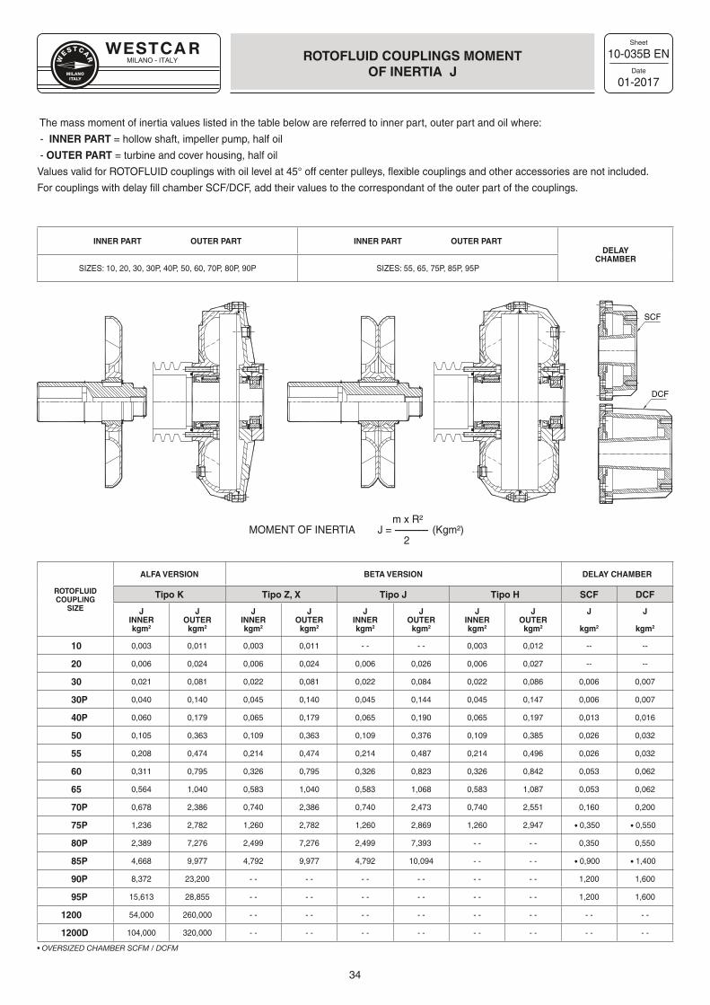
MILANO - ITALY
Sheet
Date
34
10-035B EN
01-2017
ROTOFLUID COUPLINGS MOMENTOF INERTIA J
The mass moment of inertia values listed in the table below are referred to inner part, outer part and oil where:
- INNER PART = hollow shaft, impeller pump, half oil
- OUTER PART = turbine and cover housing, half oil
Values valid for ROTOFLUID couplings with oil level at 45° off center pulleys, flexible couplings and other accessories are not included.
For couplings with delay fill chamber SCF/DCF, add their values to the correspondant of the outer part of the couplings.
INNER PART OUTER PART INNER PART OUTER PARTDELAY
CHAMBERSIZES: 10, 20, 30, 30P, 40P, 50, 60, 70P, 80P, 90P SIZES: 55, 65, 75P, 85P, 95P
m x R² MOMENT OF INERTIA J = --------------- (Kgm²) 2
ROTOFLUID COUPLING
SIZE
ALFA VERSION BETA VERSION DELAY CHAMBER
Tipo K Tipo Z, X Tipo J Tipo H SCF DCF
JINNERkgm2
JOUTER
kgm2
JINNERkgm2
JOUTER
kgm2
JINNERkgm2
JOUTER
kgm2
JINNERkgm2
JOUTER
kgm2
J
kgm2
J
kgm2
10 0,003 0,011 0,003 0,011 - - - - 0,003 0,012 -- --
20 0,006 0,024 0,006 0,024 0,006 0,026 0,006 0,027 -- --
30 0,021 0,081 0,022 0,081 0,022 0,084 0,022 0,086 0,006 0,007
30P 0,040 0,140 0,045 0,140 0,045 0,144 0,045 0,147 0,006 0,007
40P 0,060 0,179 0,065 0,179 0,065 0,190 0,065 0,197 0,013 0,016
50 0,105 0,363 0,109 0,363 0,109 0,376 0,109 0,385 0,026 0,032
55 0,208 0,474 0,214 0,474 0,214 0,487 0,214 0,496 0,026 0,032
60 0,311 0,795 0,326 0,795 0,326 0,823 0,326 0,842 0,053 0,062
65 0,564 1,040 0,583 1,040 0,583 1,068 0,583 1,087 0,053 0,062
70P 0,678 2,386 0,740 2,386 0,740 2,473 0,740 2,551 0,160 0,200
75P 1,236 2,782 1,260 2,782 1,260 2,869 1,260 2,947 • 0,350 • 0,550
80P 2,389 7,276 2,499 7,276 2,499 7,393 - - - - 0,350 0,550
85P 4,668 9,977 4,792 9,977 4,792 10,094 - - - - • 0,900 • 1,400
90P 8,372 23,200 - - - - - - - - - - - - 1,200 1,600
95P 15,613 28,855 - - - - - - - - - - - - 1,200 1,600
1200 54,000 260,000 - - - - - - - - - - - - - - - -
1200D 104,000 320,000 - - - - - - - - - - - - - - - -
• OVERSIZED CHAMBER SCFM / DCFM
SCF
DCF
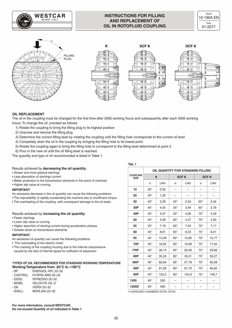
MILANO - ITALY
Sheet
Date
35
Results achieved by decreasing the oil quantity:• Slower and more gradual startings • Less absorption of startings current• Better protection to the transmission elements in the event of overload• Higher slip value at running.
IMPORTANT: An excessive decrease in the oil quantity can cause the following problems:• The impossibility of rapidly accelerating the machine due to insufficient torque.• The overheating of the coupling, with consequent damage to the oil seals.
Results achieved by increasing the oil quantity:• Faster startings• Lower slip value at running • Higher absortion of starting current during acceleration phases• Greater strain on transmission elements.
IMPORTANT: An excessive oil quantity can cause the following problems:• The overloading of the electric motor• The cracking of the coupling housing due to the internal overpressure caused by the lack of internal space for sufficient oil expansion
TYPES OF OIL RECOMMENDED FOR STANDARD WORKING TEMPERATUREWorking Temperature from -20°C to +180°C- BP ENERGOL HPL 22÷32- CASTROL HYSPIN AWS 22÷32- ESSO SPINESSO 22÷32- MOBIL VELOCITE OIL D- Q8 VERDI 22÷32- SHELL MORLINA 22÷32
10-190A EN
01-2017
INSTRUCTIONS FOR FILLINGAND REPLACEMENT OF
OIL IN ROTOFLUID COUPLING
3 04 56 0
7 5
9 0
WE
S
TC
A R
RO
TO
F
LUID
α
FILLINGPLUG
K SCF K DCF K
OIL REPLACEMENTThe oil in the coupling must be changed for the first time after 2000 working hours and subsequently after each 4000 working hours. To change the oil, proceed as follows:
1) Rotate the coupling to bring the filling plug to its highest position2) Unscrew and remove the filling plug3) Determine the correct filling level by rotating the coupling until the filling hole corresponds to the current oil level4) Completely drain the oil in the coupling by bringing the filling hole to its lowest point5) Rotate the coupling again to bring the filling hole to correspond to the filling level determined at point 36) Pour in the new oil until the oil filling level is reached.
The quantity and type of oil recommended is listed in Table 1.
For more information, consult WESTCAR.Do not exceed Quantity of oil indicated in Table 1.
Tab. 1
COUPLING SIZE
OIL QUANTITY FOR STANDARD FILLING
K SCF K DCF K
α Liter α Liter α Liter
10 45° 0,55 -- -- -- --
20 45° 1,20 -- -- -- --
30 45° 2,39 55° 2,43 65° 2,42
30P 45° 4,05 55° 3,94 65° 3,78
40P 45° 4,07 55° 4,06 70° 4,09
50 45° 4,39 65° 4,37 75° 4,59
55 45° 7,19 60° 7,04 70° 7,17
60 45° 8,61 65° 8,23 75° 8,41
65 45° 13,48 60° 12,80 70° 12,77
70P 45° 18,05 65° 16,89 75° 17,64
•75P 45° 30,14 65° 29,36 75° 29,68
80P 45° 35,53 65° 35,21 75° 35,27
•85P 45° 60,64 65° 57,79 75° 56,28
90P 45° 91,92 60° 81,70 70° 90,62
95P 45° 153,3 60° 154,9 70° 146,7
1200 45° 200 -- -- -- --
1200D 45° 400 -- -- -- --
• OVERSIZED CHAMBERS SCFM, DCFM
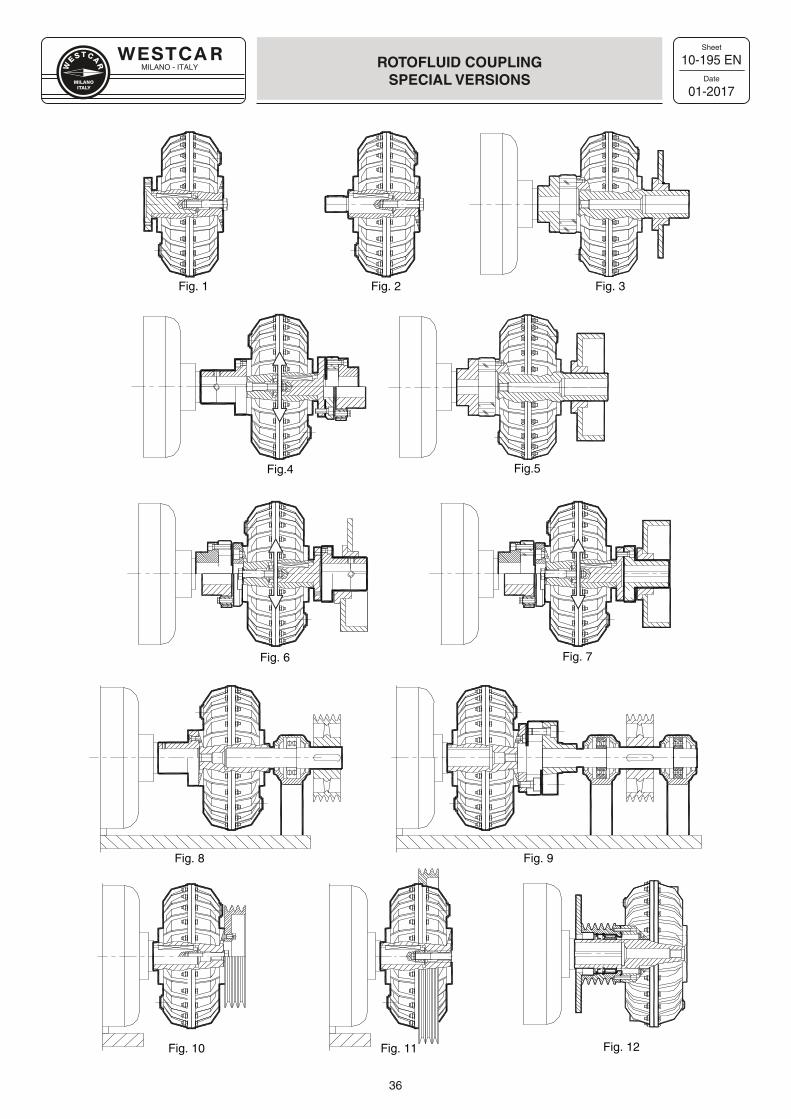
MILANO - ITALY
Sheet
Date
36
10-195 EN
01-2017
ROTOFLUID COUPLING SPECIAL VERSIONS
Fig. 8 Fig. 9
Fig. 3
Fig. 12
Fig.4
Fig. 1 Fig. 2
Fig. 10 Fig. 11
Fig. 6 Fig. 7
Fig.5
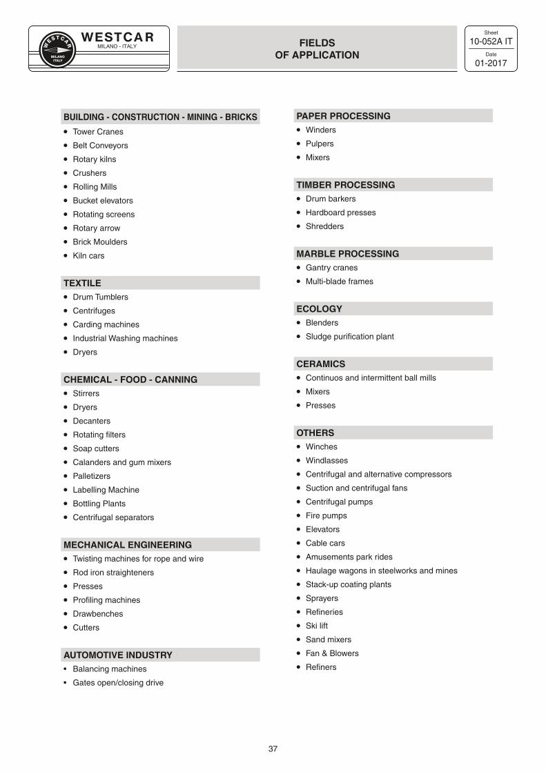
MILANO - ITALY
Sheet
Date
37
10-052A IT
01-2017
FIELDSOF APPLICATION
BUILDING - CONSTRUCTION - MINING - BRICKS
• Tower Cranes
• Belt Conveyors
• Rotary kilns
• Crushers
• Rolling Mills
• Bucket elevators
• Rotating screens
• Rotary arrow
• Brick Moulders
• Kiln cars
TEXTILE
• Drum Tumblers
• Centrifuges
• Carding machines
• Industrial Washing machines
• Dryers
CHEMICAL - FOOD - CANNING
• Stirrers
• Dryers
• Decanters
• Rotating filters
• Soap cutters
• Calanders and gum mixers
• Palletizers
• Labelling Machine
• Bottling Plants
• Centrifugal separators
MECHANICAL ENGINEERING
• Twisting machines for rope and wire
• Rod iron straighteners
• Presses
• Profiling machines
• Drawbenches
• Cutters
AUTOMOTIVE INDUSTRY• Balancing machines
• Gates open/closing drive
PAPER PROCESSING
• Winders
• Pulpers
• Mixers
TIMBER PROCESSING
• Drum barkers
• Hardboard presses
• Shredders
MARBLE PROCESSING
• Gantry cranes
• Multi-blade frames
ECOLOGY
• Blenders
• Sludge purification plant
CERAMICS
• Continuos and intermittent ball mills
• Mixers
• Presses
OTHERS
• Winches
• Windlasses
• Centrifugal and alternative compressors
• Suction and centrifugal fans
• Centrifugal pumps
• Fire pumps
• Elevators
• Cable cars
• Amusements park rides
• Haulage wagons in steelworks and mines
• Stack-up coating plants
• Sprayers
• Refineries
• Ski lift
• Sand mixers
• Fan & Blowers
• Refiners
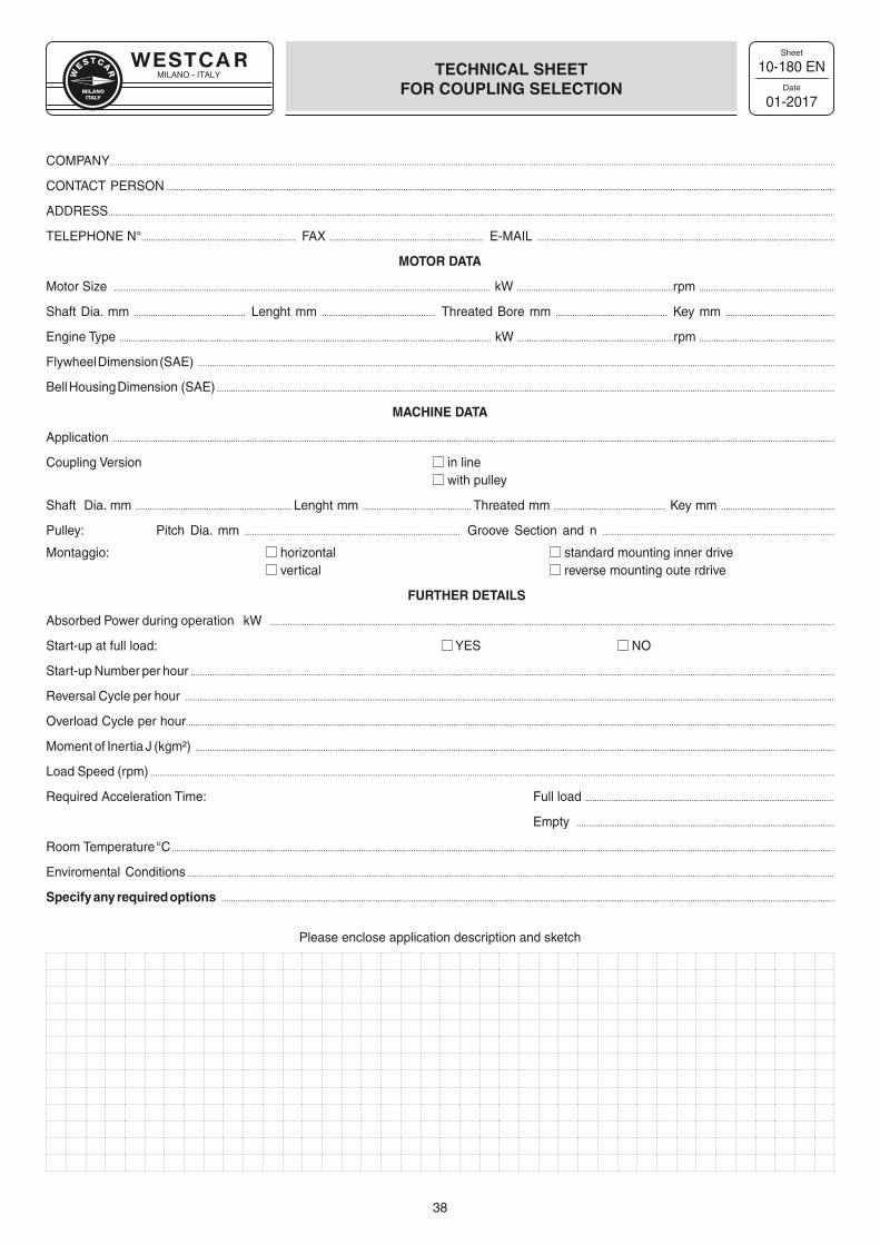
MILANO - ITALY
Sheet
Date
38
10-180 EN
01-2017
TECHNICAL SHEET FOR COUPLING SELECTION
COMPANY..........................................................................................................................................................................................................................................................................................................
CONTAC T PERSON .............................................................................................................................................................................................................................................................................................
ADDRESS................................................................................................................................................................................................................................................................................................................
TELEPHONE N°................................................................. FAX ................................................................. E-MAIL ..............................................................................................................................
MOTOR DATA
Motor Size ............................................................................................................................................................... kW ..................................................................rpm .........................................................
Shaft Dia. mm ............................................... Lenght mm ................................................ Threated Bore mm ............................................... Key mm ..............................................
Engine Type ............................................................................................................................................................. kW ..................................................................rpm .........................................................
Flywheel Dimension (SAE) .............................................................................................................................................................................................................................................................................
Bell Housing Dimension (SAE) .....................................................................................................................................................................................................................................................................
MACHINE DATA
Application .................................................................................................................................................................................................................................................................................................................
Coupling Version in line with pulley
Shaft Dia. mm .................................................................. Lenght mm .............................................. Threated mm ............................................... Key mm ................................................
Pulley: Pitch Dia. mm ........................................................................................... Groove Section and n ..................................................................................................
Montaggio: horizontal standard mounting inner drive vertical reverse mounting oute rdrive
FURTHER DETAILS
Absorbed Power during operation kW ..............................................................................................................................................................................................................................................
Start-up at full load: YES NO
Start-up Number per hour ................................................................................................................................................................................................................................................................................
Reversal Cycle per hour ..................................................................................................................................................................................................................................................................................
Overload Cycle per hour..................................................................................................................................................................................................................................................................................
Moment of Inertia J (kgm²) ..............................................................................................................................................................................................................................................................................
Load Speed (rpm) .................................................................................................................................................................................................................................................................................................
Required Acceleration Time: Full load .........................................................................................................
Empty .............................................................................................................
Room Temperature °C ........................................................................................................................................................................................................................................................................................
Enviromental Conditions ..................................................... .............................................................................................................................................................................................................................
Specify any required options ...................................................................................................................................................................................................................................................................
Please enclose application description and sketch
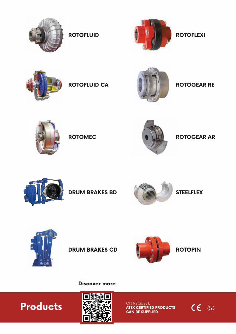
Products ON REQUEST,ATEX CERTIFIED PRODUCTSCAN BE SUPPLIED.
ROTOFLUID
ROTOFLUID CA
ROTOMEC
DRUM BRAKES BD
DRUM BRAKES CD
Discover more
ROTOFLEXI
ROTOGEAR RE
ROTOGEAR AR
STEELFLEX
ROTOPIN
R

WESTCAR WORLDWIDE
2304
6-EN
- 2
018/
03
W
ESTCAR
MILANOITALY
WESTCAR s.r.l.HeadquarterVia Monte Rosa, 14 - 20149 Milano (ITALY)Ph. +39 02 761 10 319 - Fax +39 02 761 10 041
Production PlantVia Venezia, 31 - 21058 Solbiate Olona (VA - ITALY)[email protected] - www.westcar.it
Distributor
AlbaniaAustraliaBelarusBelgium
Bosnia and HerzegovinaBrazil
CanadaChileChina
ColombiaCroatia
Czech RepublicDenmark
EgyptEstonia
FinlandFrance
Germany Great Britain
GreeceHolland
IranKoreaLatvia
LithuaniaMacedonia
MoroccoNew Zealand
NorwayPakistan
PeruPoland
PortugalRomania
RussiaSerbia
SingaporeSlovak Republic
Slovenia South Africa
SpainSwedenThailandTurkey
USA