Embed Size (px)
Citation preview

www.ktr.com
Fluid couplingsHydrodynamic power transmission according to the Föttinger principle

2
Competence meets creativity
As a leading manufacturer of high-quality drive and brake components as well as hydraulic components, KTR sup- plies mechanical couplings, clamping sets, torque limiters, measuring systems, hydraulic components and high-power brakes all over the world. With more than 50 years expe- rience in power transmission we are trendsetters in the development of coupling technology and offer customised solutions to all industries. The KTR trademark characteri- ses quality and innovation, speed, reliability, flexibility and a close working relationship with customers.
Having started with the curved-tooth gear coupling BoWex® and the torsionally flexible jaw coupling ROTEX®, KTR has built up an extensive product portfolio covering torques from 0,1 up to 1.000.000 Nm. The production by KTR’s in-house, up-to-date machinery ensures that the couplings are made to the utmost accuracy. The couplings having a unit weight of up to 2 tons or more. Flexible auto- mation ensures a quick and low-cost production even if the product has to be customised to meet customers individual specifications. KTR produces several million coup- lings a year.
Even though KTR’s standard product portfolio is quite extensive, it only represents a fraction of the different options available. KTR is not only a subcontractor but also a solution provider. The knowledge gained from thousands of applications in the field allows us to find optimum, low-cost solutions for customised applications. We will consult you during the planning stage providing drawings and prototypes or arranging for local discussions if required. Every year KTR produces more than 10.000 new products ordered by customers. This trend increases year on year. This leads to many special products becoming standard items: We permanently give vital ideas to the Power Trans-mission technology – in cooperation with our customers.
We move the world: KTR

3
Our latest scheduling system SAP ERP ensures anoptimum networking with our customers and allows for aquick and reliable delivery service. A selection of 3.500couplings and hydraulic components are permanentlyavailable from stock. For orders placed by 2:00 pm weguarantee the despatch of orders the same day! In the KTRLogistics Centre the overall fl ow of goods is supervisedby radio-controlled barcode scanning. Leading distributionpartners ensure delivery on time. Our tracking and tracingsystem allows you to follow the progress of your order atall times. KTR supplies to every location in the world.
For further details about us and our products: www.ktr.com
Accuracy meets speed
KTR products are evidence of well-designed, quality com-ponents resulting in improved characteristics of the drive or brake system and as a consequence, a longer service life ofmachines. It is our aim to continually improve the quality ofour products and services. We can analyse the stiffness ofcomponents by utilising FEM (Finite Element Method) systemsand we can also perform torsional vibration calculationsfor entire drive systems. In our in-house Research andDevelopment Centre we test our products on accurate testbenches in realistic operating conditions. Our main objectiveis to provide you with the uppermost satisfaction.
Our technical sales engineers and our well-trained salesstaff will be pleased to give you advice. KTR provides youwith extensive services online, too: At www.ktr.com youcan request information, including our product catalogue,3D-CAD-models and assembly instructions. For standardapplications you can select your drive component from more than 3.500 standard products. Having selected whichone is the right component for your application by usingour online calculation program, you are now in a position toorder the products by contacting your nearest KTR company.Alternatively our KTR Shop is open 24 hours a day.

4
Föttinger principle – with KTR
More than 50 years of experience in power transmission, more than 20 subsidiaries and 90 dealers throughout the world, this is KTR. As a leading supplier of couplings, clamping sets, torque limiters, torque measuring systems, hydraulic components, brake systems and now also fl uid couplings we are the right partner for all those who want to set things in motion.
Unlimited drive to serve our customers in the best possible way
One of the main characteristics of KTR is its effort to meet customer needs by providing customized and innovative engineering solutions. Moreover, we search for opportunities to
complement our product portfolio in a constant attempt to serve our customers in the best possible way, and to be regarded and highly valued as a system supplier.Fluid couplings are a new addition to our product portfolio which enables us to offer a broader product portfolio for e.g. applications in the mining industry or specifi c applications such as cooling towers and centrifuges. With regards to mining applications we supply fl exible couplings, brakes and electronic control systems for accu-rate brake processes. Fluid couplings may fi nd applications in belt conveyors, bucket excavators, crushers and stackers to name a few. As to cooling towers and centrifuges we can provide laminae couplings and elastic couplings res-pectively - as well as fl uid couplings.

5
A smart product for diverse applications
In general, typical applications for fl uid couplings may be found where acceleration of large masses is required (e. g. conveyer belts, centrifuges), and start-up must be gentle. Fluid couplings limit starting torque and hence re lieve the engine as the motor can start under low load conditions. Due to the limitation of the starting torque, the engine can reach 80-85 % of its speed within a few seconds. As the starting torque is limited by the fl uid coupling, and the motor starts almost load-free, start-up current is low (Fig. 1).In the case of overload, slip increases and motor and driven machine are protected as torque transmission via fl uid coupling decreases.
Another benefi t of fl uid couplings is that almost no wear occurs since torque is transmitted via a fl uid.KTR offers various types of constant-fi ll fl uid couplings in order to serve a wide range of application areas.
ATEX
KTR is actively associated with governing associations, for instance with the introduction of the ATEX product stan-dard 94/9/EC, well known as ATEX 95. The standard de-fi nes the use of products in hazardous areas. We are here to support you, to make sure that you adhere to every safety standard and to advise you of the necessary markings.
Please consult with our technical sales engineers or your local KTR offi ce.
Fig. 1: Absorbed start-up current with and without fl uid coupling
0
100
200
300
400
500
600
0
20 40 60 80 100
Star
t-up
curre
nt %
Time %
Without coupling
With coupling

6
Standstill Start-up Nominal OperationStandstill Start-up Nominal OperationStandstill Start-up Nominal OperationStand-still Start-up Nominal operation
Hydrodynamic couplings
The operating principle of hydrodynamic couplings is based on the Föttinger principle: as opposed to the direct working principle, where, for instance, power is transmitted via mechanical couplings, hydrodynamic couplings transmit power by means of a fl uid. Since torque transmission is realized via a fl uid there is almost no wear in comparison to the direct working principle.
Inner drive
Figure 3 depicts a fl uid coupling at standstill, during start-up and at nominal operation. During start-up the input shaft (driving side) mechanically transfers torque to the inner wheel (impeller) of the fl uid coupling. Mechanical energy is con-verted to kinetic energy which in turn gradually acceleratesthe outer wheel (runner). Torque transmission from outer wheel to driven machine takes place mechanically.Due to the gradual transmission of torque by meansof the hydrodynamic coupling, motors can basicallystart unloaded. Slippage of the coupling initially amounts to 100 % then steadily decreases as torque transmission increases, allowing for a soft start-up. An even softer start-up can be realized by fi tting fl uid couplings with delay chambers (Fig. 2).
Before start-up fl uid rests in both the working circuit and the delay chamber. After run-up of the motor, the entire fl uid gradually fl ows into the working circuit, thus providing for an even slower and softer start-up.
Outer drive
The driving end mechanically transfers torque to the outer wheel. Mechanical energy is converted to kinetic energy which in turn gradually accelerates the outer wheel (runner). Torque transmission from outer wheel to driven machine takes place mechanically.
Fig. 3: Working principle of fl uid
MILANO - ITALY
Foglio /
Data /
La particolarità del giunto ROTOFLUID-CA, appare più evidente confrontando le curve di avviamento dei diversi tipi di giunti idraulici a riempimento costante. The ROTOFLUID-CA peculiarities are more evident comparing the starting curves of different fluid coupling
VARI TIPI DI GIUNTI DIFFERENT COUPLING TYPES
10-080E
14-01-13
Motor torque / drive side
Fig. 2: Torque curves of fl uid coupling with no delay chambers and delay chambers of varying sizes
Torque curves / driven side
Torque
Rated torque
t
Slip at nominal speed
The slip of hydrodynamic couplings at nominal speed varies depending on coupling size and oil fi lling level.
Start-factor: 1.8-2.0 1.5-1.8 1.2-1.5 1.0-1.2
Start-factor: 1.8-2.01.5-1.81.2-1.51.0-1.2
Torque
Rated torque

7
Hydrodynamic couplings at a glance
KTR offers an extensive range of fl uid couplings for standard IEC motors and NEMA motors. Different requirements and fl uid coupling types as well as designs entail and necessitate varying performance data:
z We can cover differing power ranges depending on speed and type of hydraulic coupling
z Fluid couplings may be supplied for vertical assembly z Starting torque may be limited to 100 % - 200 % of nominal motor torque
Further, KTR can supply various types:
z Depending on required starting torque single, double and en-larged delay chambers may be supplied.
z Fluid coupling with pulley z Inner or outer drive z Fluid couplings that provide for mechanical lock-up at nominal speed thus preventing slippage
Complementary KTR-products
Our fl uid couplings may be complemented with our fl exible, gear-type and torsionally stiff couplings. Examples are given below:
- ROTEX®, ROTEX® type CF- REVOLEX®
- POLY-NORM®
- GEARex®
If long distances need to be bridged, KTR´s coupling RADEX®-N type NANA, with composite spacer, is re commended. KTR can also provide brake discs/drums if required as well as disc brakes (hydraulically and spring applied).
7
re commended. KTR can also provide brake discs/drums if required as well as disc brakes (hydraulically and spring applied).

8
Hydrodynamic couplings
Fluid couplings for IEC - motors 1)
MotorsMotor speed 50 Hz Motor speed 60 Hz
8-pole 6-pole 4-pole 2-pole 6-pole 4-pole750 1/min 1000 1/min 1500 1/min 3000 1/min 1200 1/min 1800 1/min
Size Shaft end dxl [mm] kW HP Coupling kW HP Coupling kW HP Coupling kW HP Coupling kW HP Coupling kW HP Coupling
71 14x30 0,25 0,330,25 0,33 0,37 0,5
0,25 0,330,25 0,35
10 0,37 0,5 0,55 0,75 0,37 0,5
80 19x400,37 0,5 0,55 0,75
100,75 1 0,37 0,5 10 0,55 0,75
0,55 0,7520
0,75 1 1,1 1,510
0,55 0,75 0,75 1 1090S
24x500,75 1 1,1 1,5 1,5 2 0,75 1 1,1 1,5
90L 0,55 0,75 20 1,1 1,5 1,5 2 2,2 3 1,1 1,5
20
1,5 2
100L28x60
1,1 1,5 30 1,5 230
2,2 33 4 1,5 2
2,2 33 4 20 3 4
112M 1,5 230P
2,2 3 4 5,5 4 5,5 2,2 3 4 5,520
132S38x80
2,2 3 3 430P
5,5 7,55,5 7,5
3 4 5,5 7,530
7,5 10 30
132M 3 4 40P4 5,5
7,5 105,5 7,5 20 4 5,5
7,5 105,5 7,5
40P7,5 10 5,5 7,5
160M42x110
4 5,5 50 7,5 10 11 1530P
11 157,5 10 30P 11 15
3015 20
160L 7,5 1055
11 1550
15 20 18,5 25 11 1540P
15 20180M
48x110 11 15 15 2018,5 25
40P 22 3030 15 20 18,5 25
30P180L
55
22 30 15 20 22 30
200L 55x110 15 2060 18,5 25
30 4030 40 18,5 25
5030 40 40P
22 30 50 37 5022 30
225S55x110 60x140
18,5 2565
30 4037 50 45 60 30P 37 50
50225M 22 30 60 45 60
5545 60 30 40 55 45 60
250M 60x140 65x140 30 40 37 5065
55 75 55 75 40P 37 5060
55 7555
280S75x140
37 5070P
45 60 75 10060
75 100 45 60 75 100280M 45 60 55 75 70P 90 125 90 125
5055 75 90 125
60315S
65x14080x170
55 7575P
75 100 110 15065
110 150 75 100 65 110 150
315M75 100 90 125 75P 132 180 132 180 90 125
70P132 180
6590 125
80P110 150 160 220
70P160 220 55 110 150 160 220
110 150 132 180 200 270 132 180 200 27070P
355S75x140 95x170
132 180 160 220 80P 250 340 160 22075P
250 34085P 75P
355M160 220 200 270
85P 315 430200 270
315 430 75P200 270 90P 250 340 250 340 80P
Non standard motors
330 450 90P 370 500 85P 510 700 80P 310 420 80P 440 600 75P600 800 95P 600 800 90P 810 1100 85P 440 600 85P 700 950 80P
1000 1360 1200 1000 1360 95P 1300 1740 90P 800 1100 90P 1000 1360 85P1550 2100 1200/2 2000 2720 1200 2300 3100 95P 1380 1880 95P
3200 4350 1200/2 3850 5250 1200 2580 3500 12004200 5710 1200/2
1) Fluid couplings available for NEMA - motors
IEC - motors - selection

9
Hydrodynamic couplings
1000 30001500
0,25
0,5
1
0,75
1,5
3
2
4
7,5
5,5
10
600
20
15
2530
40506075
150
100125
180220270
350
500420
1000800700
12001500
20002500
[HP]
3000
50 Hz
0,37
0,75
0,55
1,1
2,2
1,5
3
5,5
4
7,5
440
15
11
18,522
30374555
110
7590
132160200
260
365310
730600510
8801100
14701840
[kW]
2200
0,18
[1/min.]
25703500
900 1200 1800 3600
750
60 Hz 600 6000
2000 5000500
40005000
29333667
6000 4410
10
20
3030
P40
P50
5560
6570
P
75P80
P85
P90
P95
P
1200
/2
1200
Selection diagram

10
Technical data
SizeDimensions [mm]Basic coupling
max. fi nish bore Ød1 DA L LG D1 H7 l1 D2 zxM l2
1024
193 8898
474
60 6x M612
28 114 2 9
2028
230 115125 62
4 78 6x M816
38 135 52 14
3042
290 150162 75
4 100 8x M8 1648 190 7255 219 72
30P42
327 150162 75
4 100 8x M8 1648 190 7255 219 72
40P55
338 183 198100
4 125 8x M1022
60 90 2050 65 430 154 179 110 4,5 140 8x M10 22
5565
430 196211
110 4,5 140 8x M10 2275 210
6075
520 172192
125 8 160 8x M10 2280 222
65 80 520 220 240 125 8 160 8x M10 22
70P90
640 190240
150 4 195 8x M16 30100 280
75P90
640 245265
150 4 195 8x M16 30100 280
80P110
810 226270
160 5 230 8x M18 28125 286
85P125
810 300 340 160 5 230 8x M18 28135
90P130
1000 344364
445 5 506 16x M20 32140 464
95P130
1000 466479
445 5 506 16x M20 32140 586
1200 max. 190 1300 425 462 220 7 310 16x M20 36
Type K z Basic version of constant fill couplings z Consists of pump and turbine wheel, outer shell z Starting factor: 1.8-2 z Inner and outer drive possible: z The coupling is usually mounted on the motor shaft (inner drive). Outer drive on request (coupling is mounted on gearbox shaft).
z Flexible couplings are used to compensate for misalignments
1) Finish bore acc. to ISO fi t H7, feather keyway acc. to DIN 6885 sheet 1 - JS9Finish bore Ø ≤32: H7; Finish bore Ø ≥33: G7Finish bore length: min. 2xd; max. 2,5xd
Hydrodynamic couplings
zxM

11
Technical dataDimensions [mm]
Basic coupling Small delay chamber Enlarged delay chamberSize max. finish bore Ød1 DA L D1 H7 l1 D2 zxM l2 LGS LGE
3042
290 15075
4 100 8x M8 16217 257
48 72 245 28555 72 274 314
30P42
327 15075
4 100 8x M8 16217 257
48 72 245 28555 72 274 314
40P 60 338 183 90 4 125 8x M10 20 256 32850 65 430 154 110 4,5 140 8x M10 22 259 334
5565
430 196 110 4,5 140 8x M10 22291 366
75 290 365
6075
520 172 125 8 160 8x M10 22282 362
80 312 39265 80 520 220 125 8 160 8x M10 22 330 410
70P90
640 190 150 4 195 8x M16 30350 465
100 390 505
75P90
640 245 150 4 195 8x M16 30375 490
100 390 505
80P110
810 226 160 5 230 8x M18 28388 488
125 404 504
85P125
810 300 160 5 230 8x M18 28 458 558135
90P130
1000 344 445 5 506 16x M20 32424 504
140 524 604
95P130
1000 466 445 5 506 16x M20 32599 679
140 706 786
Type K with small and enlarged delay chamber
zxM
z The basic type “K” is fitted with a delay chamber. The delay chamber is flange-mounted to the outer wheel of the hydro-dynamic coupling.
z Start-up factor: 1.5-1.8 (small delay chamber) z Start-up factor: 1.2-1.5 (enlarged delay chamber)
z Due to the reduced start-up factor even smoother and longer start-ups of the driven machine are enabled.
z Inner and outer drive possible z Flexible couplings allow for compensation of misalignments
Fluid couplings: small delay chamber Fluid couplings: enlarged delay chamber
1) Finish bore acc. to ISO fit H7, feather keyway acc. to DIN 6885 sheet 1- JS9 Finish bore Ø ≤32: H7; Finish bore Ø ≥33: G7 Finish bore length: min. 2xD; max. 2,5xD
Hydrodynamic couplings

12
Hydrodynamic couplings
Technical data
SizeDimensions [mm]Basic coupling
max. fi nish bore Ød1 DA Ls LG dsh6 ls
1024
193 35133
19 2528 149
2028
230 44169
24 3238 179
3042
290 63225
38 4548 25355 282
30P42
327 63225
38 4548 25355 282
40P55
338 76 274 48 5560
50 65 430 92 271 55 65
5565
430 92303
55 6575 302
6075
520 110302
60 8080 332
65 80 520 110 350 60 80
70P90
640 122362
70 90100 402
75P90
640 122387
70 90100 402
80P110
810 145415
80 110125 431
85P125
810 145 485 80 110135
90P130
1000 220584
110 180140 684
95P130
1000 220699
160 180140 806
1200 190 1300 290 752 180 250
Type K fi tted with output shaft
1) Finish bore acc. to ISO fi t H7, feather keyway acc. to DIN 6885 sheet 1 - JS9Finish bore Ø ≤32: H7; Finish bore Ø ≥33: G7Finish bore length: min. 2xd; max. 2,5xd
z Fluid coupling is fitted with output shaft z Also delay chambers can be provided for this version. Delay chambers are flange-connected to the coupling, and the output shaft is flange-connected to the delay chamber.
z Flexible coupling can be mounted on the output shaft and allow for compensation of misalignments

13
Hydrodynamic couplings
Technical data
SizeDimensions [mm]
DA LG DF D3 zxE zxM l3 l220 230 150 116 95,25 6x6,4 6x 1/4 28 UNF 6,5 1730 290 192,5
152,5 122,22 8x9,57 8x 3/8 24 UNF 6,518,5
30P 327 192,540P 338 231
2150 430 21255 430 253
213 177,8 10x12,57 10x 1/2 20 UNF 1024,5
60 520 23525,5
65 520 28370P 640 258,5
240 206,37 8x15,875 8x 1/2 20 UNF 10 25,575P 640 313,580P 810 355
280 241,3 8x19,05 8x 3/4 10 UNF 28 5085P 810 42590P 1000 456 318 279,4 8x19,05 8x 3/4 10 UNF 28 50
Fluid coupling for flanged gear type couplingsz x
E
z Fluid coupling can be fitted with GEARex®
z GEARex® type FR with single parted sleeve z GEARex® type DR with split sleeve z Also delay chambers can be provided for this version.

14
Hydrodynamic couplings
Technical data
SizeDimensions [mm]
max. finish bore Ød1 DA L1 zxM dl ds h6 ls D3=D4 D5h7=D6
h7 D7=D8 z1xM
1019
240 128 4x M10 4x Ø1119
25 165 130 200 8x M1024 24
20 28 292 161 4x M12 4x Ø13 28 32 215 180 250 8x M112
30 38 350 210 4x M12 4x Ø13 38 45 265 230 300 8x M12
30P 42 400 210 4x M16 4x Ø17 42 45 300 250 350 8x M16
40P 48 400 255 4x M16 4x Ø17 48 48 300 250 350 8x M16
Fluid coupling with housing
d
ds h
6
6
d
ds h
6
6 z Fluid coupling is fitted with housing z To be fitted to electric motors (flange motors) and hollow shaft gearbox
1) Finish bore acc. to ISO fit H7, feather keyway acc. to DIN 6885 sheet 1 - JS9 Finish bore Ø ≤32: H7; Finish bore Ø ≥33: G7 Finish bore length: min. 2xd; max. 2,5xd
Flange mounted gearbox Foot mounted gearbox

15
Hydrodynamic couplings
Technical data
SizeDimensions [mm]
max. finish bore Ød1 DA LG Dph7 D9 lpmax zxM
2028
229185 60 75 70
6x M838 218 75 90 8542 218 85 100 50
3055 230 96 110 6242 290 238 85 100 70 8x M842 262 85 100 9455 285 96 110 11742 218 85 100 50
30P55 230 96 110 6242 327 238 85 100 70 8x M842 262 85 100 9455 285 96 110 117
40P
48
338
247
112 130
63
8x M860 273 8960 301 11760 325 141
50 65 430
244
130 150
70
8x M8274 100309 135334 160
55 65 430
286
130 150
70
8x M8316 100351 135356 180
80
302 110
60342 150
520 350 150 170 158 8x M10390 198402 210
65 80 520
350
150 170
110
8x M10390 150440 200475 235
70P 100 640
380
188 210
140
8x M12420 180440 200485 245
75P 100 640
420
188 210
130
8x M12470 1801490 200535 245
80P
100
810
386214 240
1308x M14100 436 180
100 481 225125 481 225 250 143 8x M16
85P
100
810
460214 240
1308x M14100 530 200
100 555 225125 555 225 250 143 8x M16
Hydrodynamic coupling with pulley z Diverse pulleys on request z Coupling can be fitted with delay chambers z Vertical and horizontal assembly possible
1) Finish bore acc. to ISO fit H7, feather keyway acc. to DIN 6885 sheet 1 - JS9 Finish bore Ø ≤32: H7; Finish bore Ø ≥33: G7 Finish bore length: min. 2xd; max. 2,5xd

16
Hydrodynamic coupling with mechanical lock-up at nominal speed
Hydrodynamic coupling with and annular chamber
Additional types
z Fluid coupling is fitted with enlarged delay chamber and annu-lar chamber
z Start-up factor can be further reduced to 1.0-1.2 z Due to the reduced start-up factor even smoother and longer start-ups of the driven machine are enabled.
z Inner and outer drive possiblez Flexible couplings allow for compensation of misalignments
z Hydraulic coupling which provides for smooth acceleration z Mechanical lock-up at nominal operation (similar to centrifugal clutch)
z No slip at nominal operation z Can be offered with delay chambers, pulleys, output shaft
Hydrodynamic couplings
17
Monitoring devices
Hydrodynamic couplings
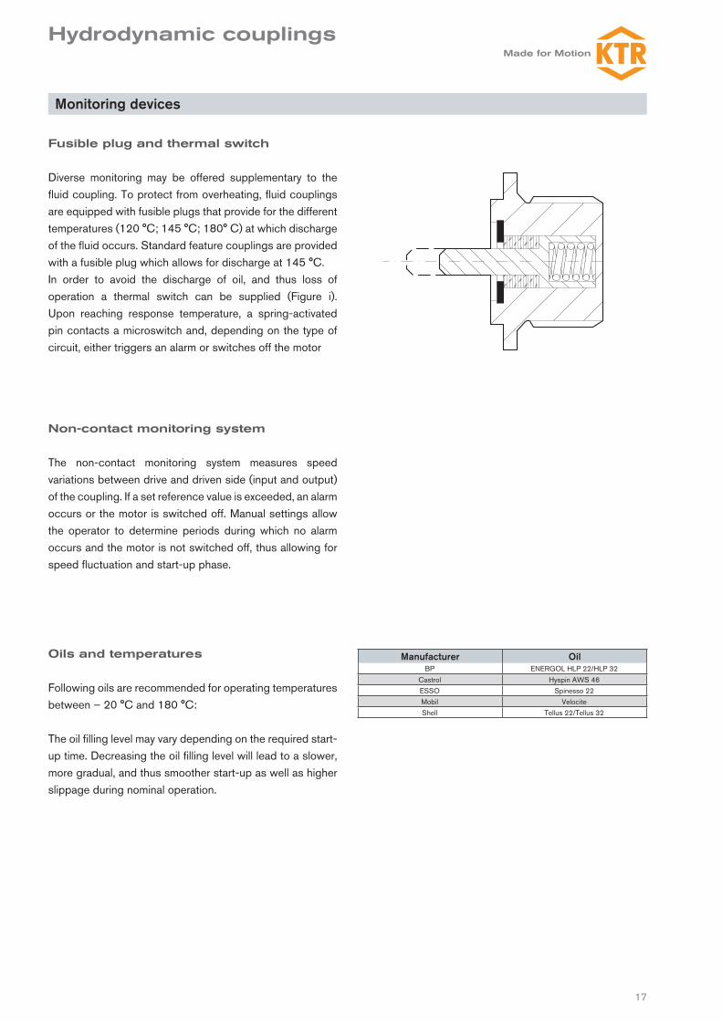
Fusible plug and thermal switch
Diverse monitoring may be offered supplementary to the fluid coupling. To protect from overheating, fluid couplings are equipped with fusible plugs that provide for the different temperatures (120 °C; 145 °C; 180° C) at which discharge of the fluid occurs. Standard feature couplings are pro vided with a fusible plug which allows for discharge at 145 °C.In order to avoid the discharge of oil, and thus loss of operation a thermal switch can be supplied (Figure i). Upon reaching response temperature, a spring-activated pin contacts a microswitch and, depending on the type of circuit, either triggers an alarm or switches off the motor
Oils and temperatures
Following oils are recommended for operating temperatures between – 20 °C and 180 °C:
The oil filling level may vary depending on the required start-up time. Decreasing the oil filling level will lead to a slower, more gradual, and thus smoother start-up as well as higher slippage during nominal operation.
Non-contact monitoring system
The non-contact monitoring system measures speed variations between drive and driven side (input and output) of the coupling. If a set reference value is exceeded, an alarm occurs or the motor is switched off. Manual settings allow the operator to determine periods during which no alarm occurs and the motor is not switched off, thus allowing for speed fluctuation and start-up phase.
Manufacturer OilBP ENERGOL HLP 22/HLP 32
Castrol Hyspin AWS 46ESSO Spinesso 22Mobil VelociteShell Tellus 22/Tellus 32

18
Questionnaire: Technical selection
Hydrodynamic couplings

19
KTR-STOP® Fluid coupling; POLY-NORM®; brake drum
Fluid coupling RADEX®-N Type NANA Fluid coupling and ROTEX®
Hydraulics
Everything from one single source.KTR - your system supplier
KTR-STOP®
KTR-STOP® is the recently developed brake system of KTR. It was designed for applications with high forces and adverse environmental conditions.
Coupling with brake drum/-disc
KTR produce drive components for numerous industrial applications. Our couplings are often delivered combined with an integrated brake drum/disc.
Hydraulics
The brake calipers of KTR-STOP® are activated via the hyd-raulic power pack and for that reason we provide both solid and reliable power pack components for use under the hea-viest conditions.
IntelliRamp®
IntelliRamp® is the newly developed control system for re-producing brake processes with consideration for speed against time.
KTR worldwide:Belgium/LuxemburgKTR Benelux B. V. (Bureau Belgien)Blancefloerlaan 167/22B-2050 AntwerpenPhone:Fax:E-mail:
+32 3 2110567+32 3 [email protected]
BrazilKTR do Brasil Ltda.Rua Jandaia do Sul 471 - Bairro Emiliano Perneta Pinhais - PR - Cep: 83321-040BrasilPhone:Fax:E-mail:
+55 41 36 69 57 13+55 41 36 69 57 [email protected]
CanadaKTR Corporation122 Anchor RoadMichigan City, Indiana 46360USAPhone:Fax:E-mail:
+1 2 19 8 72 91 00+1 2 19 8 72 91 [email protected]
ChinaKTR Power Transmission Technology(Shanghai) Co. Ltd. Building 1005, ZOBON Business Park999 Wangqiao RoadPudongShanghai 201201ChinaPhone:Fax:E-mail:
+86 21 58 38 18 00+86 21 58 38 19 [email protected]
Czech RepublicKTR CR, spol. s. r. o.Olomoucká 226CZ-569 43 JevíckoPhone:Fax:E-mail:
+420 461 325 162+420 461 325 [email protected]
FinlandKTR Finland OYTiistinniityntie 4SF-02230 EspooPL 23SF-02231 EspooPhone:Fax:E-mail:
+358 2 07 41 46 10+358 2 07 41 46 [email protected]
FranceKTR France S.A.R.L.46 – 48 Chemin de la BruyèreF-69570 DardillyPhone:Fax:E-mail:
+33 478 64 54 66+33 478 64 54 [email protected]
Great BritainKTR Couplings Ltd. Robert HouseUnit 7, Acorn Business ParkWoodseats CloseSheffieldEngland, S8 0TBPhone:Fax:E-mail:
+44 11 42 58 77 57+44 11 42 58 77 [email protected]
IndiaKTR Couplings (India) Pvt. Ltd.,T-36 / 37 / 38, MIDC BhosariPune 411026IndiaPhone:Fax:E-mail:
+91 20 27 12 73 22+91 20 27 12 73 [email protected]
ItalyKTR Kupplungstechnik GmbHSede senza rappresentanza stabile sul Territorio NazionaleVia Fermi, 25I-40033 Casalecchio di Reno (BO)Phone:Fax:E-mail:
+39 051 613 32 32+39 02 700 37 [email protected]
JapanKTR Japan Co., Ltd.3-1-23 DaikaidoriHyogo-ku, Kobe-shi652-0803 JapanPhone:Fax:E-mail:
+81 7 85 74 03 13+81 7 85 74 03 [email protected]
KTR Japan – Tokyo Office1-11-6, Higashi-Ueno, Taito-Ku,Tokyo 110-0015 Japan(Takeno-building, 5F)JapanPhone:Fax:
+81 3 58 18 32 07+81 3 58 18 32 08
KoreaKTR Korea Ltd.# 101, 978-10, Topyung-DongGuri-City, Gyeonggi-Do471-060 KoreaPhone:Fax:E-mail:
+82 3 15 69 45 10+82 3 15 69 45 [email protected]
NetherlandsKTR Benelux B. V.Postbus 87NL-7550 AB Hengelo (O)Adam Smithstraat 37NL-7559 SW Hengelo (O)Tel.:Fax:E-Mail:
+31 74 2553680+31 74 [email protected]
NorwayKTR Kupplungstechnik Norge ASFjellbovegen 13N-2016 FrognerPhone:Fax:E-mail:
+47 64 83 54 90+47 64 83 54 [email protected]
PolandKTR Polska SP. Z. O. O.ul. Czerwone Maki 65PL – 30-392 KrakówPhone:Fax:E-mail:
+48 12 267 28 83+48 12 267 07 [email protected]
PortugalKTR Kupplungstechnik GmbHc) Estartetxe, n° 5 – Oficina 218E-48940 Leioa (Vizcaya)Phone:Fax:E-mail:
+34 9 44 80 39 09+34 9 44 31 68 [email protected]
RussiaKTR Privodnaya technika, LLC6 Verhnii Pereulok 12Litera A, Office 229194292 St. PetersburgRussiaPhone:Fax:E-mail:Internet:
+7 812 383 51 20+7 812 383 51 [email protected]
SpainKTR Kupplungstechnik GmbHc) Estartetxe, n° 5 – Oficina 218E-48940 Leioa (Vizcaya)Phone:Fax:E-mail:
+34 9 44 80 39 09+34 9 44 31 68 [email protected]
SwedenKTR Sverige ABBox 742S - 191 27 SollentunaPhone:Fax:E-mail:
+46 86 25 02 90+46 86 25 02 [email protected]
SwitzerlandKTR Kupplungstechnik AGBahnstr. 60CH - 8105 RegensdorfPhone:Fax:E-mail:
+41 4 33 11 15 55+41 4 33 11 15 [email protected]
TaiwanKTR Taiwan Ltd.1 F, No.: 17, Industry 38 RoadTaichung Industry ZoneTaichungTaiwan, R. O. C.Phone:Fax:E-mail:
+886 4 23 59 32 78+886 4 23 59 75 [email protected]
TurkeyKTR TurkeyGüç Aktarma Sistemleri San. ve Tic. Ltd. Sti.Kayışdagı Cad. No: 117/2 34758 Atasehir -İstanbulPhone:Fax:E-mail:
+90 216 574 37 80+90 216 574 34 [email protected]
USAKTR Corporation122 Anchor RoadMichigan City, Indiana 46360USAPhone:Fax:E-mail:
+1 2 19 8 72 91 00+1 2 19 8 72 91 [email protected]
KTR Kupplungstechnik GmbHPostfach 1763D-48407 RheinePhone:Fax:E-mail:Internet:
+49(0)5971 798-0+49(0)5971 798-698 u. 798-4 [email protected]
06/1
3 - T
echn
isch
e Ä
nder
unge
n vo
rbeh
alte
n.