Embed Size (px)
Citation preview
FLUID COOLERS
SELECTION GUIDEand
OPERATION and MAINTENANCE
MANUAL

3
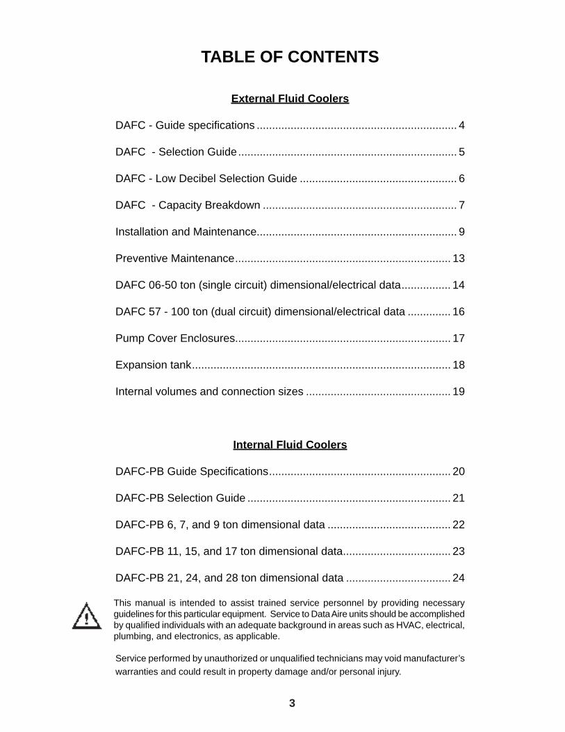
TABLE OF CONTENTS
External Fluid Coolers
DAFC - Guide specifi cations ................................................................. 4
DAFC - Selection Guide ....................................................................... 5
DAFC - Low Decibel Selection Guide ................................................... 6
DAFC - Capacity Breakdown ............................................................... 7
Installation and Maintenance................................................................. 9
Preventive Maintenance ...................................................................... 13
DAFC 06-50 ton (single circuit) dimensional/electrical data ................ 14
DAFC 57 - 100 ton (dual circuit) dimensional/electrical data .............. 16
Pump Cover Enclosures...................................................................... 17
Expansion tank .................................................................................... 18
Internal volumes and connection sizes ............................................... 19
Internal Fluid Coolers
DAFC-PB Guide Specifi cations ........................................................... 20
DAFC-PB Selection Guide .................................................................. 21
DAFC-PB 6, 7, and 9 ton dimensional data ........................................ 22
DAFC-PB 11, 15, and 17 ton dimensional data ................................... 23
DAFC-PB 21, 24, and 28 ton dimensional data .................................. 24
This manual is intended to assist trained service personnel by providing necessary guidelines for this particular equipment. Service to Data Aire units should be accomplished by qualifi ed individuals with an adequate background in areas such as HVAC, electrical, plumbing, and electronics, as applicable.
Service performed by unauthorized or unqualifi ed technicians may void manufacturer’s warranties and could result in property damage and/or personal injury.
4
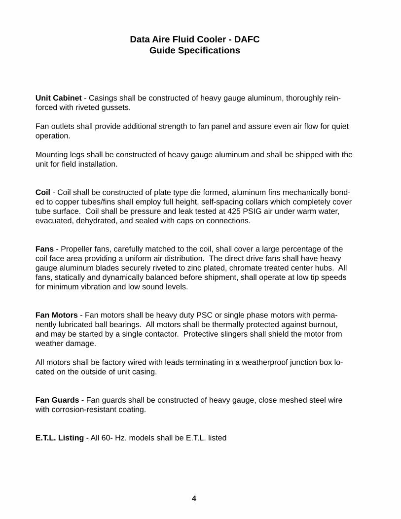
Data Aire Fluid Cooler - DAFCGuide Specifi cations
Unit Cabinet - Casings shall be constructed of heavy gauge aluminum, thoroughly rein-forced with riveted gussets.
Fan outlets shall provide additional strength to fan panel and assure even air fl ow for quiet operation.
Mounting legs shall be constructed of heavy gauge aluminum and shall be shipped with the unit for fi eld installation.
Coil - Coil shall be constructed of plate type die formed, aluminum fi ns mechanically bond-ed to copper tubes/fi ns shall employ full height, self-spacing collars which completely cover tube surface. Coil shall be pressure and leak tested at 425 PSIG air under warm water, evacuated, dehydrated, and sealed with caps on connections.
Fans - Propeller fans, carefully matched to the coil, shall cover a large percentage of the coil face area providing a uniform air distribution. The direct drive fans shall have heavy gauge aluminum blades securely riveted to zinc plated, chromate treated center hubs. All fans, statically and dynamically balanced before shipment, shall operate at low tip speeds for minimum vibration and low sound levels.
Fan Motors - Fan motors shall be heavy duty PSC or single phase motors with perma-nently lubricated ball bearings. All motors shall be thermally protected against burnout, and may be started by a single contactor. Protective slingers shall shield the motor from weather damage.
All motors shall be factory wired with leads terminating in a weatherproof junction box lo-cated on the outside of unit casing.
Fan Guards - Fan guards shall be constructed of heavy gauge, close meshed steel wire with corrosion-resistant coating.
E.T.L. Listing - All 60- Hz. models shall be E.T.L. listed
5
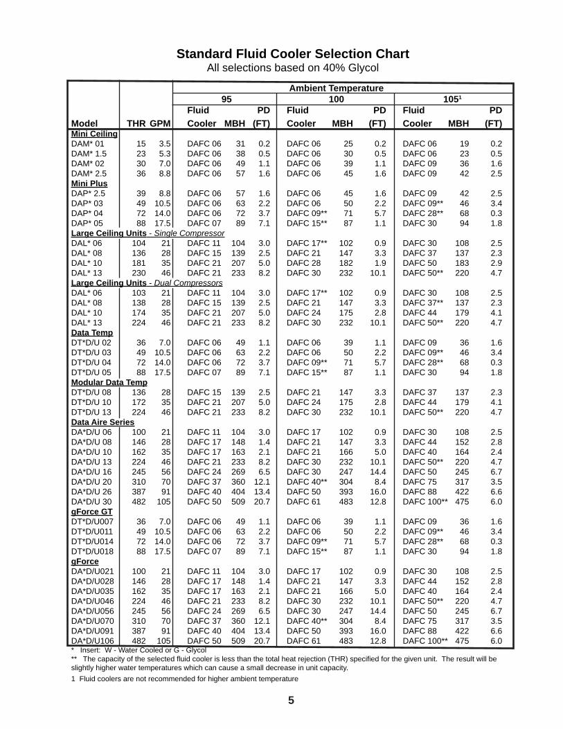
Standard Fluid Cooler Selection ChartAll selections based on 40% Glycol
Ambient Temperature 95 100 1051
Fluid PD Fluid PD Fluid PDModel THR GPM Cooler MBH (FT) Cooler MBH (FT) Cooler MBH (FT)Mini CeilingDAM* 01 15 3.5 DAFC 06 31 0.2 DAFC 06 25 0.2 DAFC 06 19 0.2DAM* 1.5 23 5.3 DAFC 06 38 0.5 DAFC 06 30 0.5 DAFC 06 23 0.5DAM* 02 30 7.0 DAFC 06 49 1.1 DAFC 06 39 1.1 DAFC 09 36 1.6DAM* 2.5 36 8.8 DAFC 06 57 1.6 DAFC 06 45 1.6 DAFC 09 42 2.5Mini PlusDAP* 2.5 39 8.8 DAFC 06 57 1.6 DAFC 06 45 1.6 DAFC 09 42 2.5DAP* 03 49 10.5 DAFC 06 63 2.2 DAFC 06 50 2.2 DAFC 09** 46 3.4DAP* 04 72 14.0 DAFC 06 72 3.7 DAFC 09** 71 5.7 DAFC 28** 68 0.3DAP* 05 88 17.5 DAFC 07 89 7.1 DAFC 15** 87 1.1 DAFC 30 94 1.8Large Ceiling Units - Single CompressorDAL* 06 104 21 DAFC 11 104 3.0 DAFC 17** 102 0.9 DAFC 30 108 2.5DAL* 08 136 28 DAFC 15 139 2.5 DAFC 21 147 3.3 DAFC 37 137 2.3 DAL* 10 181 35 DAFC 21 207 5.0 DAFC 28 182 1.9 DAFC 50 183 2.9DAL* 13 230 46 DAFC 21 233 8.2 DAFC 30 232 10.1 DAFC 50** 220 4.7Large Ceiling Units - Dual CompressorsDAL* 06 103 21 DAFC 11 104 3.0 DAFC 17** 102 0.9 DAFC 30 108 2.5DAL* 08 138 28 DAFC 15 139 2.5 DAFC 21 147 3.3 DAFC 37** 137 2.3 DAL* 10 174 35 DAFC 21 207 5.0 DAFC 24 175 2.8 DAFC 44 179 4.1DAL* 13 224 46 DAFC 21 233 8.2 DAFC 30 232 10.1 DAFC 50** 220 4.7Data TempDT*D/U 02 36 7.0 DAFC 06 49 1.1 DAFC 06 39 1.1 DAFC 09 36 1.6DT*D/U 03 49 10.5 DAFC 06 63 2.2 DAFC 06 50 2.2 DAFC 09** 46 3.4 DT*D/U 04 72 14.0 DAFC 06 72 3.7 DAFC 09** 71 5.7 DAFC 28** 68 0.3DT*D/U 05 88 17.5 DAFC 07 89 7.1 DAFC 15** 87 1.1 DAFC 30 94 1.8Modular Data TempDT*D/U 08 136 28 DAFC 15 139 2.5 DAFC 21 147 3.3 DAFC 37 137 2.3DT*D/U 10 172 35 DAFC 21 207 5.0 DAFC 24 175 2.8 DAFC 44 179 4.1DT*D/U 13 224 46 DAFC 21 233 8.2 DAFC 30 232 10.1 DAFC 50** 220 4.7Data Aire SeriesDA*D/U 06 100 21 DAFC 11 104 3.0 DAFC 17 102 0.9 DAFC 30 108 2.5DA*D/U 08 146 28 DAFC 17 148 1.4 DAFC 21 147 3.3 DAFC 44 152 2.8DA*D/U 10 162 35 DAFC 17 163 2.1 DAFC 21 166 5.0 DAFC 40 164 2.4DA*D/U 13 224 46 DAFC 21 233 8.2 DAFC 30 232 10.1 DAFC 50** 220 4.7DA*D/U 16 245 56 DAFC 24 269 6.5 DAFC 30 247 14.4 DAFC 50 245 6.7DA*D/U 20 310 70 DAFC 37 360 12.1 DAFC 40** 304 8.4 DAFC 75 317 3.5DA*D/U 26 387 91 DAFC 40 404 13.4 DAFC 50 393 16.0 DAFC 88 422 6.6DA*D/U 30 482 105 DAFC 50 509 20.7 DAFC 61 483 12.8 DAFC 100** 475 6.0gForce GTDT*D/U007 36 7.0 DAFC 06 49 1.1 DAFC 06 39 1.1 DAFC 09 36 1.6DT*D/U011 49 10.5 DAFC 06 63 2.2 DAFC 06 50 2.2 DAFC 09** 46 3.4 DT*D/U014 72 14.0 DAFC 06 72 3.7 DAFC 09** 71 5.7 DAFC 28** 68 0.3DT*D/U018 88 17.5 DAFC 07 89 7.1 DAFC 15** 87 1.1 DAFC 30 94 1.8gForceDA*D/U021 100 21 DAFC 11 104 3.0 DAFC 17 102 0.9 DAFC 30 108 2.5DA*D/U028 146 28 DAFC 17 148 1.4 DAFC 21 147 3.3 DAFC 44 152 2.8DA*D/U035 162 35 DAFC 17 163 2.1 DAFC 21 166 5.0 DAFC 40 164 2.4DA*D/U046 224 46 DAFC 21 233 8.2 DAFC 30 232 10.1 DAFC 50** 220 4.7DA*D/U056 245 56 DAFC 24 269 6.5 DAFC 30 247 14.4 DAFC 50 245 6.7DA*D/U070 310 70 DAFC 37 360 12.1 DAFC 40** 304 8.4 DAFC 75 317 3.5DA*D/U091 387 91 DAFC 40 404 13.4 DAFC 50 393 16.0 DAFC 88 422 6.6DA*D/U106 482 105 DAFC 50 509 20.7 DAFC 61 483 12.8 DAFC 100** 475 6.0* Insert: W - Water Cooled or G - Glycol ** The capacity of the selected fl uid cooler is less than the total heat rejection (THR) specifi ed for the given unit. The result will be slightly higher water temperatures which can cause a small decrease in unit capacity.1 Fluid coolers are not recommended for higher ambient temperature
6
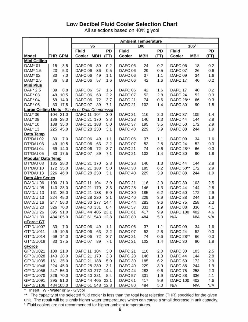
Low Decibel Fluid Cooler Selection ChartAll selections based on 40% glycol
Ambient Temperature 95 100 1051
Fluid PD Fluid PD Fluid PDModel THR GPM Cooler MBH (FT) Cooler MBH (FT) Cooler MBH (FT)Mini CeilingDAM* 01 15 3.5 DAFC 06 30 0.2 DAFC 06 24 0.2 DAFC 06 18 0.2DAM* 1.5 23 5.3 DAFC 06 36 0.5 DAFC 06 29 0.5 DAFC 07 26 0.6DAM* 02 30 7.0 DAFC 06 49 1.1 DAFC 06 37 1.1 DAFC 09 34 1.6DAM* 2.5 36 8.8 DAFC 06 57 1.6 DAFC 06 42 1.6 DAFC 17 40 0.2Mini PlusDAP* 2.5 39 8.8 DAFC 06 57 1.6 DAFC 06 42 1.6 DAFC 17 40 0.2DAP* 03 49 10.5 DAFC 06 63 2.2 DAFC 07 52 2.8 DAFC 24 52 0.3DAP* 04 69 14.0 DAFC 06 72 3.7 DAFC 21 74 0.6 DAFC 28** 66 0.3DAP* 05 83 17.5 DAFC 07 89 7.1 DAFC 21 102 1.4 DAFC 30 90 1.8Large Ceiling Units - Single or Dual CompressorDAL* 06 104 21.0 DAFC 11 104 3.0 DAFC 21 116 2.0 DAFC 37 105 1.4DAL* 08 136 28.0 DAFC 21 170 3.3 DAFC 28 146 1.3 DAFC 44 144 2.8 DAL* 10 188 35.0 DAFC 21 188 5.0 DAFC 37 195 3.5 DAFC 50 172 2.9DAL* 13 225 45.0 DAFC 28 230 3.1 DAFC 40 229 3.9 DAFC 88 244 1.9Data TempDT*D/U 02 33 7.0 DAFC 06 49 1.1 DAFC 06 37 1.1 DAFC 09 34 1.6DT*D/U 03 49 10.5 DAFC 06 63 2.2 DAFC 07 52 2.8 DAFC 24 52 0.3 DT*D/U 04 69 14.0 DAFC 06 72 3.7 DAFC 21 74 0.6 DAFC 28** 66 0.3DT*D/U 05 83 17.5 DAFC 07 89 7.1 DAFC 21 102 1.4 DAFC 30 90 1.8Modular Data TempDT*D/U 08 135 28.0 DAFC 21 170 2.3 DAFC 28 146 1.3 DAFC 44 144 2.8DT*D/U 10 172 35.0 DAFC 21 188 5.0 DAFC 30 185 6.2 DAFC 50** 172 2.9DT*D/U 13 226 46.0 DAFC 28 230 3.1 DAFC 40 229 3.9 DAFC 88 244 1.9Data Aire SeriesDA*D/U 06 100 21.0 DAFC 11 104 3.0 DAFC 21 116 2.0 DAFC 30 103 2.5DA*D/U 08 143 28.0 DAFC 21 170 3.3 DAFC 28 146 1.3 DAFC 44 144 2.8DA*D/U 10 161 35.0 DAFC 21 188 5.0 DAFC 30 185 6.2 DAFC 50 172 2.9DA*D/U 13 224 45.0 DAFC 28 230 3.1 DAFC 40 229 3.9 DAFC 88 244 1.9DA*D/U 16 247 56.0 DAFC 30 277 14.4 DAFC 44 283 9.6 DAFC 75 258 2.3DA*D/U 20 326 70.0 DAFC 40 331 8.4 DAFC 57 331 1.9 DAFC 88 336 4.1DA*D/U 26 395 91.0 DAFC 44 405 23.1 DAFC 61 417 9.9 DAFC 100 402 4.6DA*D/U 30 484 105.0 DAFC 61 543 12.8 DAFC 80 484 5.0 N/A N/A N/AgForce GTGT*D/U007 33 7.0 DAFC 06 49 1.1 DAFC 06 37 1.1 DAFC 09 34 1.6GT*D/U011 49 10.5 DAFC 06 63 2.2 DAFC 07 52 2.8 DAFC 24 52 0.3 GT*D/U014 69 14.0 DAFC 06 72 3.7 DAFC 21 74 0.6 DAFC 28** 66 0.3GT*D/U018 83 17.5 DAFC 07 89 7.1 DAFC 21 102 1.4 DAFC 30 90 1.8gForceGF*D/U021 100 21.0 DAFC 11 104 3.0 DAFC 21 116 2.0 DAFC 30 103 2.5GF*D/U028 143 28.0 DAFC 21 170 3.3 DAFC 28 146 1.3 DAFC 44 144 2.8GF*D/U035 161 35.0 DAFC 21 188 5.0 DAFC 30 185 6.2 DAFC 50 172 2.9GF*D/U046 224 45.0 DAFC 28 230 3.1 DAFC 40 229 3.9 DAFC 88 244 1.9GF*D/U056 247 56.0 DAFC 30 277 14.4 DAFC 44 283 9.6 DAFC 75 258 2.3GF*D/U070 326 70.0 DAFC 40 331 8.4 DAFC 57 331 1.9 DAFC 88 336 4.1GF*D/U091 395 91.0 DAFC 44 405 23.1 DAFC 61 417 9.9 DAFC 100 402 4.6GF*D/U106 484 105.0 DAFC 61 543 12.8 DAFC 80 484 5.0 N/A N/A N/A* Insert: W - Water or G - Glycol** The capacity of the selected fl uid cooler is less than the total heat rejection (THR) specifi ed for the given unit. The result will be slightly higher water temperatures which can cause a small decrease in unit capacity.1 Fluid coolers are not recommended for higher ambient temperatures.

7
DAFC Fluid Cooler Capacity BreakdownBased on 40% Glycol
DAFC 06 DAFC 07 DAFC 09 DAFC 11 DAFC 15 DAFC 17 DAFC 21 GPM MBH/PD MBH/PD MBH/PD MBH/PD MBH/PD MBH/PD MBH/PD
5 36.9/.04 41.7/.05 10 61.0/2.0 69.2/2.6 72.0/3.1 15 73.9/4.2 83.7/5.4 90.6/6.5 20 82.0/7.1 92.4/9.0 99.5/10.9 101.6/2.7 25 86.2/10.6 97.0/13.4 112.8/4.1 172.6/2.7 30 121.5/5.7 143.6/2.9 191.2/3.8 35 126.7/7.5 152.8/3.8 206.8/5.0 40 132.1/9.5 160.1/4.8 171.7/2.7 220.4/6.4 45 136.7/11.8 166.0/6.0 178.7/3.4 231.5/7.9 50 140.6/14.2 168.9/7.2 184.5/4.1 237.5/9.5 55 173.0/8.6 189.4/4.8 244.7/11.3 60 176.5/10.1 193.4/5.7 250.9/13.2 65 179.5/11.6 196.7/6.5 70 182.2/13.3 198.0/7.5 75 200.5/8.5 80 202.8/9.5 85 204.9/10.6 100 206.7/11.8
DAFC 24 DAFC 28 DAFC 30 DAFC 37 DAFC 40 DAFC 44 DAFC 50GPM MBH/PD MBH/PD MBH/PD MBH/PD MBH/PD MBH/PD MBH/PD 30 229.7/4.7 229.7/4.7 35 219.2/2.8 251.5/6.2 251.5/6.2 298.4/4.1 305.6/2.9 40 233.9/3.9 244.2/2.5 270.7/7.9 285.1/4.4 295.8/3.1 325.9/5.3 336.1/3.6 45 246.4/4.4 257.6/3.1 286.7/9.7 303.0/5.5 315.3/3.8 349.8/6.5 362.5/4.5 50 257.4/5.3 268.9/3.7 296.5/11.7 318.9/6.6 331.4/4.6 370.5/7.9 385.4/5.5 55 267.0/6.3 278.7/4.4 307.3/13.9 332.9/7.8 345.7/5.4 388.6/9.3 405.3/6.5 60 275.1/7.4 287.3/5.1 344.9/9.2 358.5/6.3 404.6/10.9 422.8/7.6 65 281.2/8.6 294.9/5.9 354.3/10.6 369.8/7.3 418.8/12.6 438.0/8.7 70 284.3/9.8 301.6/6.8 359.7/12.1 379.7/8.4 429.0/14.4 451.5/10.0 75 289.0/11.1 307.1/7.7 367.0/13.7 388.1/9.5 463.5/11.3 80 293.2/12.4 311.3/8.6 394.7/10.4 474.3/12.7 85 297.0/13.9 313.1/9.6 398.0/11.9 481.5/14.2 90 316.5/10.7 400.3/13.2
** Continued on next page **

8
DAFC Fluid Cooler Capacity Breakdown - ContinuedBased on 40% Glycol
DAFC 57 DAFC 61 DAFC 75 DAFC 80 DAFC 88 DAFC 100 GPM MBH/PD MBH/PD MBH/PD MBH/PD MBH/PD MBH/PD
45 379.7/2.8 50 408.8/3.4 55 435.2/4.0 60 459.4/4.7 480.0/2.6 65 482.0/5.4 505.5/3.0 70 503.1/6.2 528.9/3.5 596.8/4.1 75 522.9/7.0 550.3/3.9 625.4/4.7 642.8/3.3 80 488.3/2.5 541.4/7.9 570.1/4.4 591.6/3.1 651.8/5.3 672.2/3.6 85 502.4/2.8 558.3/8.8 588.6/4.9 611.6/3.4 676.6/5.9 699.4/4.1 90 515.2/3.1 573.4/9.7 606.0/5.5 629.9/3.8 699.6/6.5 725.0/4.5 95 527.0/3.4 586.2/10.7 622.4/6.0 647.0/4.2 721.0/7.2 748.6/5.0 100 537.8/3.7 593.0/11.7 637.8/6.6 662.8/4.6 741.0/7.9 770.8/5.5 110 557.4/4.4 614.5/13.9 665.8/7.8 691.5/5.4 777.2/9.3 810.6/6.5 120 574.6/5.1 689.8/9.2 717.0/6.3 809.2/10.9 845.6/7.6 130 589.9/5.9 708.5/10.6 739.6/7.3 837.6/12.6 876.0/8.7 140 603.1/6.8 719.5/12.1 759.4/8.4 858.0/14.4 903.0/10.0 150 614.2/7.7 734.0/13.7 776.2/9.5 927.0/11.3 160 622.7/8.6 789.4/10.7 948.6/12.7 170 626.2/9.6 796.1/11.9 963.0/14.2 180 633.0/10.7 806.7/13.2 190 639.1/11.7 816.2/14.5 200 644.6/12.9
9
Installation and Maintenance
Inspection
This Data Aire unit has been factory run-tested and passed a comprehensive inspection prior to its packaging and shipment to ensure that it arrives in excellent condition. However, shipping damage can occur and a visual inspection of the outer crating immediately upon delivery should be performed. Note any external damage or other transportation damage on the freight carrier’s forms. Inspect the unit itself for internal damage. A claim should be fi led with the shipping company if the equipment is damaged or incomplete.
Loose items such as remote control panels, disconnect switch handles, or other items are packed inside the unit. Refer to the yellow shipping tag located on the unit door for details.
Freight damage claims are the responsibility of the purchaser. Action to recover losses should be fi led immediately. Please notify factory personnel of any claims.
Location
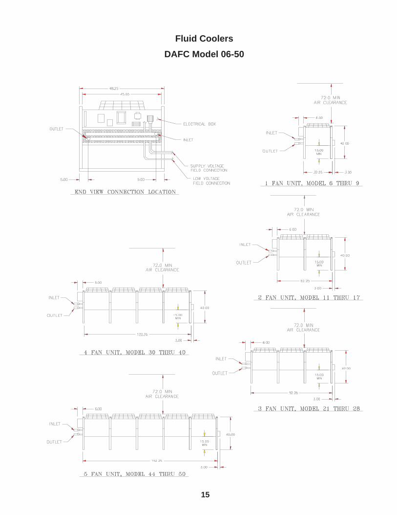
Remote heat exchangers must be located in an area that will ensure free air fl ow into and out of the unit plus adequate service clearance. The unit should not be placed any closer than 36” from any wall, with no more than two walls, or other obstruction.
With proper clearance on all other sides, two units can be placed side by side. Additional units should be placed no closer than 48” apart.
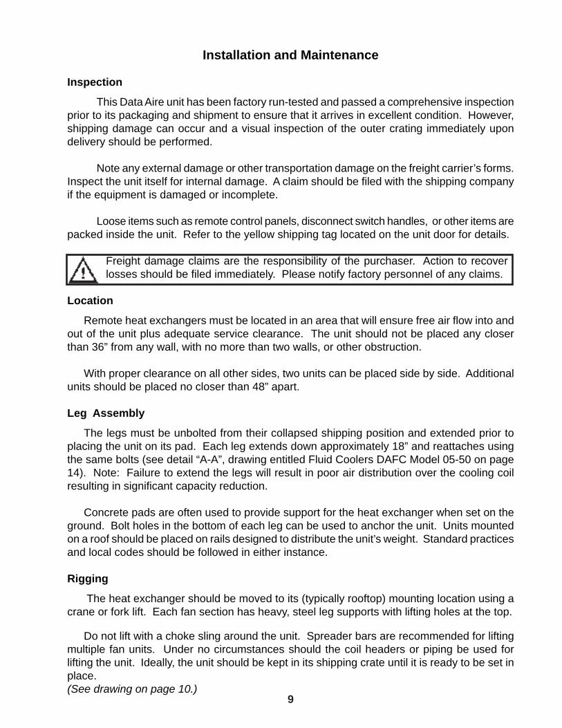
Leg Assembly
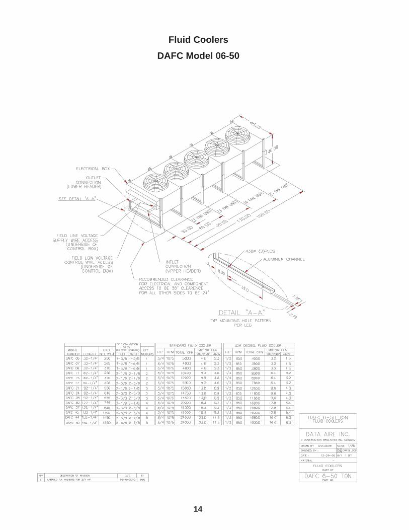
The legs must be unbolted from their collapsed shipping position and extended prior to placing the unit on its pad. Each leg extends down approximately 18” and reattaches using the same bolts (see detail “A-A”, drawing entitled Fluid Coolers DAFC Model 05-50 on page 14). Note: Failure to extend the legs will result in poor air distribution over the cooling coil resulting in signifi cant capacity reduction.
Concrete pads are often used to provide support for the heat exchanger when set on the ground. Bolt holes in the bottom of each leg can be used to anchor the unit. Units mounted on a roof should be placed on rails designed to distribute the unit’s weight. Standard practices and local codes should be followed in either instance.
Rigging
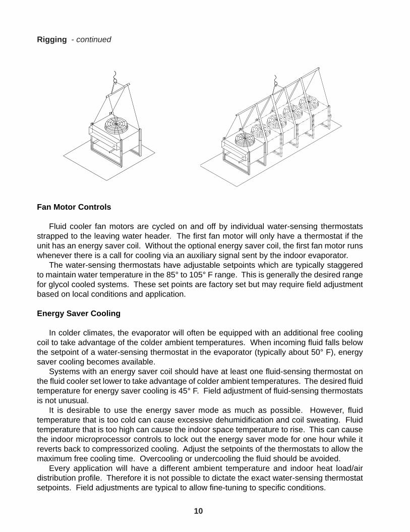
The heat exchanger should be moved to its (typically rooftop) mounting location using a crane or fork lift. Each fan section has heavy, steel leg supports with lifting holes at the top.
Do not lift with a choke sling around the unit. Spreader bars are recommended for lifting multiple fan units. Under no circumstances should the coil headers or piping be used for lifting the unit. Ideally, the unit should be kept in its shipping crate until it is ready to be set in place.(See drawing on page 10.)
10
Fan Motor Controls
Fluid cooler fan motors are cycled on and off by individual water-sensing thermostats strapped to the leaving water header. The fi rst fan motor will only have a thermostat if the unit has an energy saver coil. Without the optional energy saver coil, the fi rst fan motor runs whenever there is a call for cooling via an auxiliary signal sent by the indoor evaporator. The water-sensing thermostats have adjustable setpoints which are typically staggered to maintain water temperature in the 85° to 105° F range. This is generally the desired range for glycol cooled systems. These set points are factory set but may require fi eld adjustment based on local conditions and application.
Energy Saver Cooling
In colder climates, the evaporator will often be equipped with an additional free cooling coil to take advantage of the colder ambient temperatures. When incoming fl uid falls below the setpoint of a water-sensing thermostat in the evaporator (typically about 50° F), energy saver cooling becomes available. Systems with an energy saver coil should have at least one fl uid-sensing thermostat on the fl uid cooler set lower to take advantage of colder ambient temperatures. The desired fl uid temperature for energy saver cooling is 45° F. Field adjustment of fl uid-sensing thermostats is not unusual. It is desirable to use the energy saver mode as much as possible. However, fl uid temperature that is too cold can cause excessive dehumidifi cation and coil sweating. Fluid temperature that is too high can cause the indoor space temperature to rise. This can cause the indoor microprocessor controls to lock out the energy saver mode for one hour while it reverts back to compressorized cooling. Adjust the setpoints of the thermostats to allow the maximum free cooling time. Overcooling or undercooling the fl uid should be avoided. Every application will have a different ambient temperature and indoor heat load/air distribution profi le. Therefore it is not possible to dictate the exact water-sensing thermostat setpoints. Field adjustments are typical to allow fi ne-tuning to specifi c conditions.
Rigging - continued
11
Glycol System Concentration
Fill the system with water and suffi cient antifreeze (ethylene or propylene glycol) to protect the system against winter freeze-up. Refer to the chart below for amount of glycol required to prevent freezing.
Freezing Point of Aqueous Solutions
Ethylene Glycol Freezing Point Propylene Glycol Freezing Point % by Volume Degrees F % by Volume Degrees F 0 32° 0 32° 10 24° 10 27° 20 15° 20 18° 30 4° 30 8° 40 -13° 40 -6° 50 -33° 50 -26°
In order to achieve the appropriate glycol concentration it is necessary to know the vol-ume that the system contains. The total volume includes the amount of liquid required by the Data Aire indoor evaporator, fl uid cooler, and the interconnecting piping. Glycol percentage must be checked after installation and on periodic intervals to insure satisfactory protection. Hydrometers are required to insure an accurate reading.
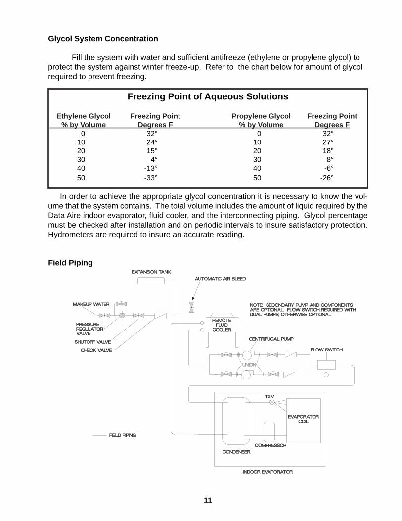
Field Piping

12
Electrical Service
Check to be sure the service provided by the utility is suffi cient to handle the additional load imposed by the fl uid coolers. Most units with secondary heat exchangers will require a separate power source and fi eld-provided, interconnecting control wires.
Glycol systems with fl uid coolers and loose pump(s) typically require one power source for the fl uid cooler and will require one additional source for a single pump or two additional sources for dual pumps. Systems where the pump(s) are mounted and piped integral to the Fluid Cooler will usually require a single power source.
Nameplate Ratings
Refer to the unit electrical nameplate for equipment electrical requirements. Minimum circuit ampacity (MCA), also known as wire sizing amps, will dictate the minimum required wire gauge. Maximum overcurrent protection (MOP) device amps will dictate the maximum circuit breaker or fuse size.
Grounding
The unit cabinet must have an uninterrupted true earth ground. An electrical ground wire of adequate size must be connected to the ground lug provided inside the main electrical box.
Voltage Tolerance
The supply voltage to the unit must be within 10% (under by 5% when voltage is 208V) of the voltage indicated on the unit electrical nameplate. Phase to phase imbalance must not exceed 3%. The local utility company should be contacted for correction of improper line voltage. Deviation from voltage ratings can cause premature failures and possibly void unit warranties.
Auxiliary Control Wiring
For control wiring to the fl uid coolers connect two 18 gauge wires from the electrical box of the indoor evaporator to the electrical box of the remote fl uid cooler. Follow the wiring diagrams for each of these pieces of equipment. On most evaporators the terminals will be #42 and #43. On most remote heat exchangers the terminals will be #39 and #40. All control wiring on Data Aire equipment is 24 VAC or less. Refer to wiring diagrams.
Check the wiring connections in the unit control panel to ensure they are tight. Screw terminals may become loose in transit. Tightening of wiring connections is the responsibility of the installing contractor.
13
Preventive Maintenance
The operating life of the DAFC fl uid cooler can be extended by following a simple preven-tive maintenance schedule. This schedule will reduce the possibility of failure of compo-nents and unnecessary malfunction of the system. Although the service technicians must be thoroughly familiar with the special design features of this equipment before attempting any service or repair, an inexperienced technician can perform certain simple maintenance functions to assure normal, trouble-free operation.
Maintenance Functions
Monthly
Check heat exchanger for obstruction to the inlet air side of coil.
Bleed air from glycol system.
Seasonally
Check electrical components for loose wire connections.
Check contactor contacts for pitting.
Check glycol solution level in the system.
Check fan motor(s)
Bi-AnnuallyCheck the glycol solution inhibitors. Inhibitor level prevents corrosion and glycol concentration prevents freezing. Flush as necessary.
Clean the coil.
Annually Check the glycol system for leaks and corrosion.
14
Fluid CoolersDAFC Model 06-50
15
Fluid CoolersDAFC Model 06-50
16
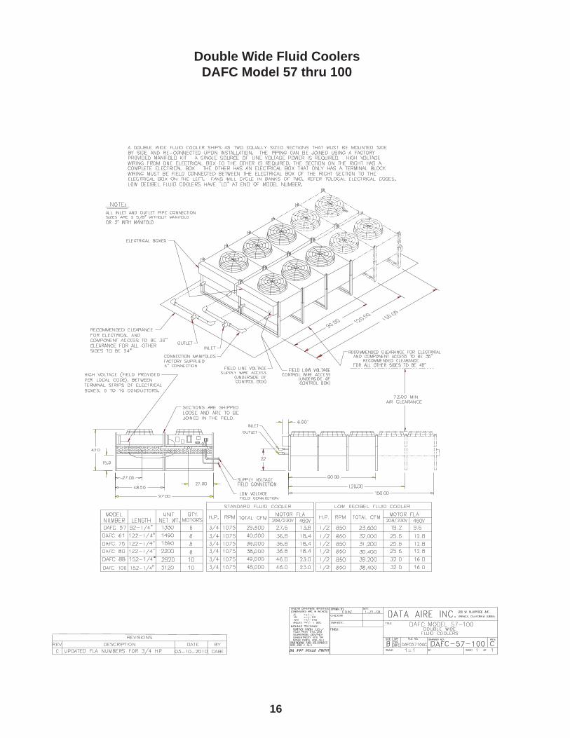
Double Wide Fluid CoolersDAFC Model 57 thru 100
17
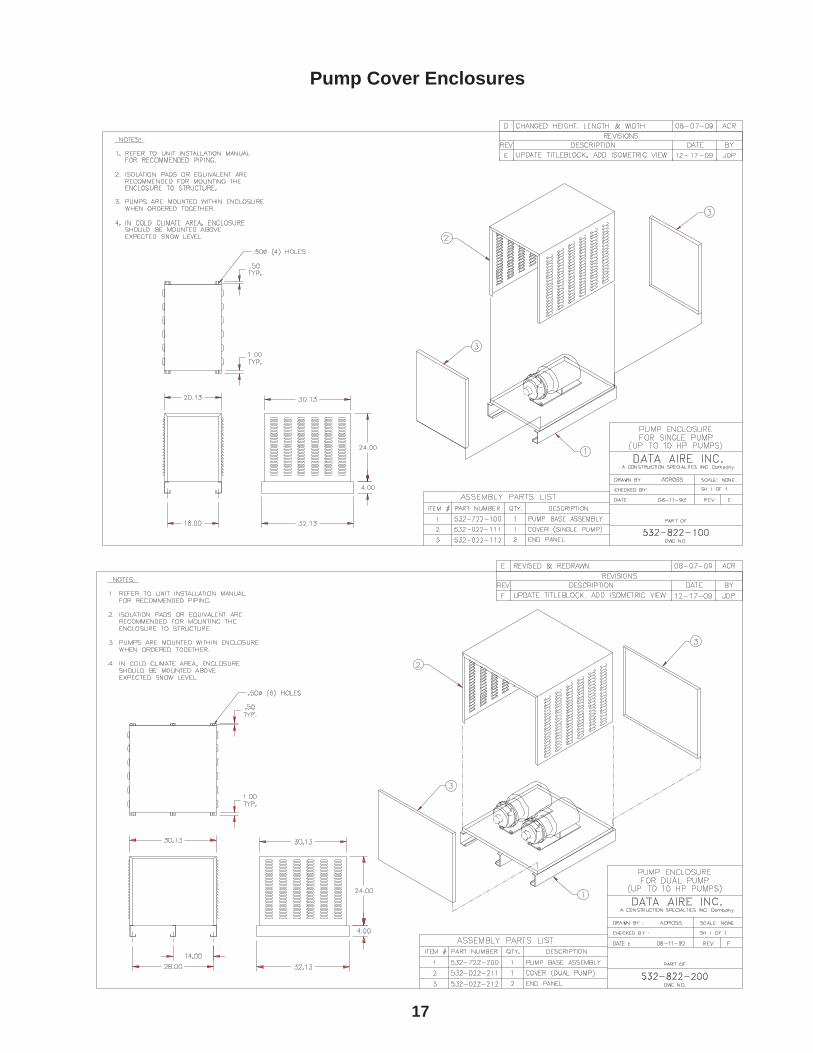
Pump Cover Enclosures
18
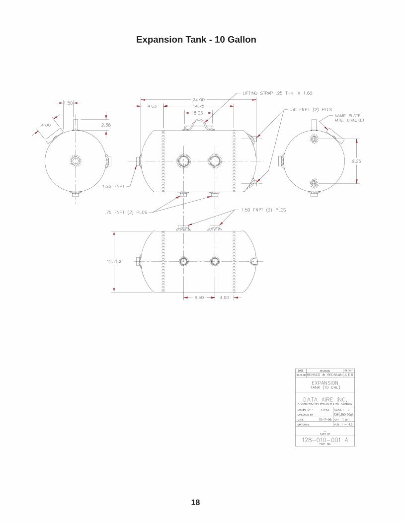
Expansion Tank - 10 Gallon
19
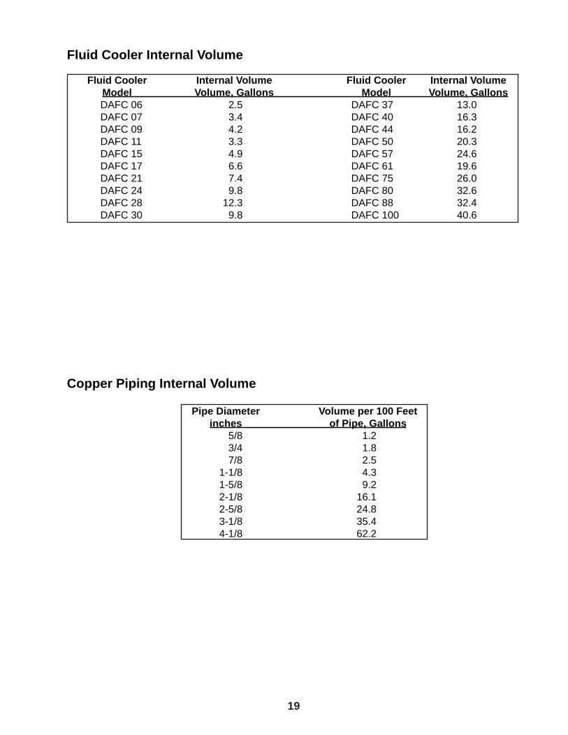
Fluid Cooler Internal Volume Fluid Cooler Internal Volume Fluid Cooler Internal Volume Model Volume, Gallons Model Volume, Gallons DAFC 06 2.5 DAFC 37 13.0 DAFC 07 3.4 DAFC 40 16.3 DAFC 09 4.2 DAFC 44 16.2 DAFC 11 3.3 DAFC 50 20.3 DAFC 15 4.9 DAFC 57 24.6 DAFC 17 6.6 DAFC 61 19.6 DAFC 21 7.4 DAFC 75 26.0 DAFC 24 9.8 DAFC 80 32.6 DAFC 28 12.3 DAFC 88 32.4 DAFC 30 9.8 DAFC 100 40.6
Copper Piping Internal Volume Pipe Diameter Volume per 100 Feet inches of Pipe, Gallons 5/8 1.2 3/4 1.8 7/8 2.5 1-1/8 4.3 1-5/8 9.2 2-1/8 16.1 2-5/8 24.8 3-1/8 35.4 4-1/8 62.2
20
DAFC-PB Fluid CoolerGuide Specifi cations
CABINET AND FRAME - The frame shall be constructed of 14 gauge welded tubular steel and be coated with a heavy corrosion inhibiting fi nish for long life. The unit shall have com-plete front and side access by means of high quality furniture grade steel doors with heavy duty hinges. The doors shall be lined with 1” thick, 1 1/2 pound density fi berglass coated with insulation. Each door shall be provided with sure close latches, which shall be painted to match or contrast with the computer equipment.
COLOR - The unit shall be painted in __________________________.
BLOWER SECTIONS - The blower section shall be belt driven centrifugal type, double width, double inlet and shall be statically and dynamically balanced at the factory as a complete as-sembly to a maximum vibration level of two mills in any plane. The blower wheel shall be a minimum of 15” diameter. The blower wheel shall be supported on a heavy steel shaft having self-aligning ball bearings with a minimum life span of 100,000 hours. The blower wheel shall be driven by a motor mounted on an adjustable slide base. The drive motor shall be 1,750 rpm. The drive package shall be belt driven with two belts and variable pitch sheave, sized for 200% of the fan motor horsepower.
COOLING COIL - The fl uid cooler cooling coil shall be constructed of copper tubes and cor-rugated aluminum fi ns.
E.T.L. Listing - All 60- Hz. models shall be E.T.L. listed.
21
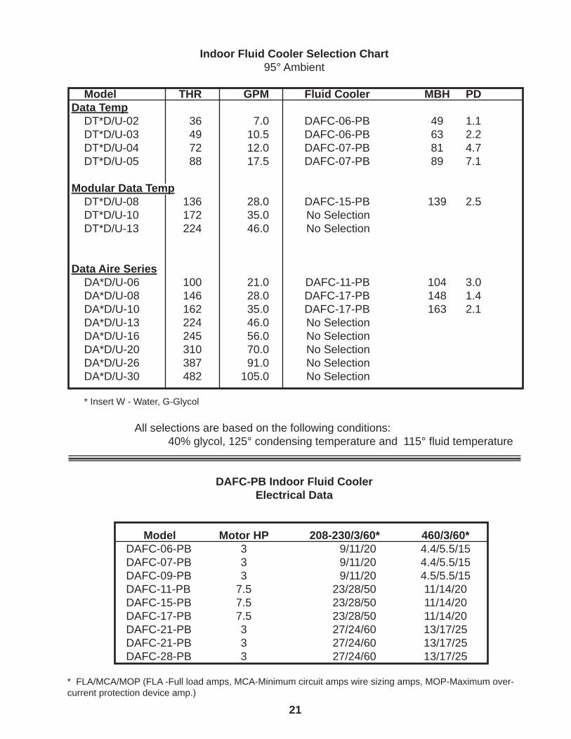
Indoor Fluid Cooler Selection Chart95° Ambient
Model THR GPM Fluid Cooler MBH PDData Temp DT*D/U-02 36 7.0 DAFC-06-PB 49 1.1 DT*D/U-03 49 10.5 DAFC-06-PB 63 2.2 DT*D/U-04 72 12.0 DAFC-07-PB 81 4.7 DT*D/U-05 88 17.5 DAFC-07-PB 89 7.1
Modular Data Temp DT*D/U-08 136 28.0 DAFC-15-PB 139 2.5 DT*D/U-10 172 35.0 No Selection DT*D/U-13 224 46.0 No Selection
Data Aire Series DA*D/U-06 100 21.0 DAFC-11-PB 104 3.0 DA*D/U-08 146 28.0 DAFC-17-PB 148 1.4 DA*D/U-10 162 35.0 DAFC-17-PB 163 2.1 DA*D/U-13 224 46.0 No Selection DA*D/U-16 245 56.0 No Selection DA*D/U-20 310 70.0 No Selection DA*D/U-26 387 91.0 No Selection DA*D/U-30 482 105.0 No Selection
* Insert W - Water, G-Glycol
All selections are based on the following conditions: 40% glycol, 125° condensing temperature and 115° fl uid temperature
DAFC-PB Indoor Fluid CoolerElectrical Data
Model Motor HP 208-230/3/60* 460/3/60* DAFC-06-PB 3 9/11/20 4.4/5.5/15 DAFC-07-PB 3 9/11/20 4.4/5.5/15 DAFC-09-PB 3 9/11/20 4.5/5.5/15 DAFC-11-PB 7.5 23/28/50 11/14/20 DAFC-15-PB 7.5 23/28/50 11/14/20 DAFC-17-PB 7.5 23/28/50 11/14/20 DAFC-21-PB 3 27/24/60 13/17/25 DAFC-21-PB 3 27/24/60 13/17/25 DAFC-28-PB 3 27/24/60 13/17/25
* FLA/MCA/MOP (FLA -Full load amps, MCA-Minimum circuit amps wire sizing amps, MOP-Maximum over-current protection device amp.)
22
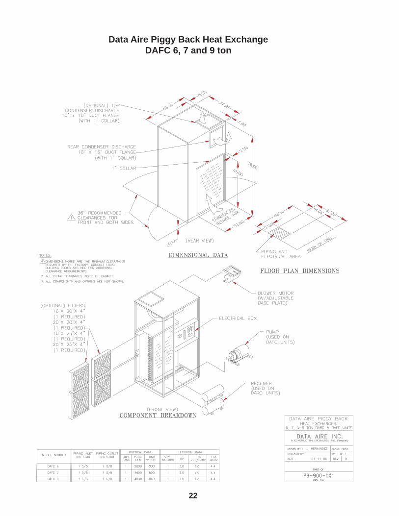
Data Aire Piggy Back Heat ExchangeDAFC 6, 7 and 9 ton
23
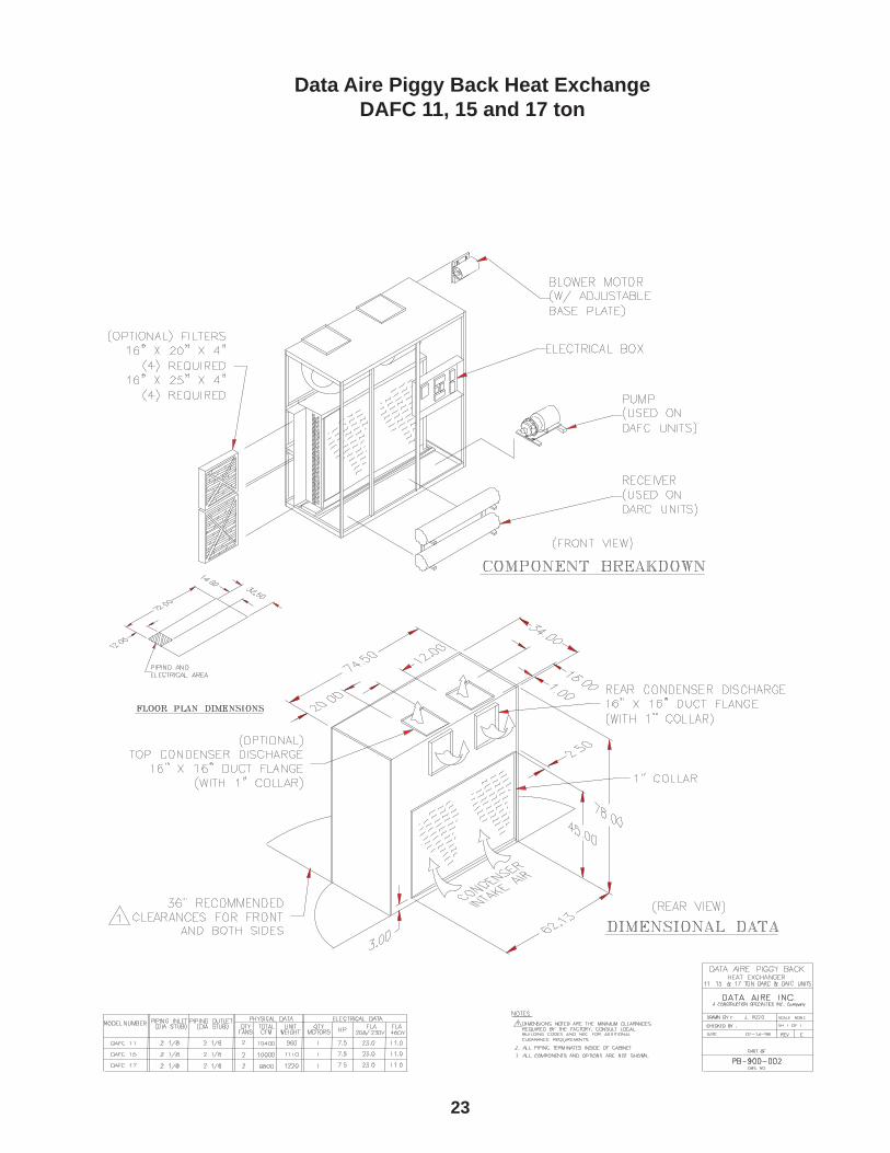
Data Aire Piggy Back Heat ExchangeDAFC 11, 15 and 17 ton
24
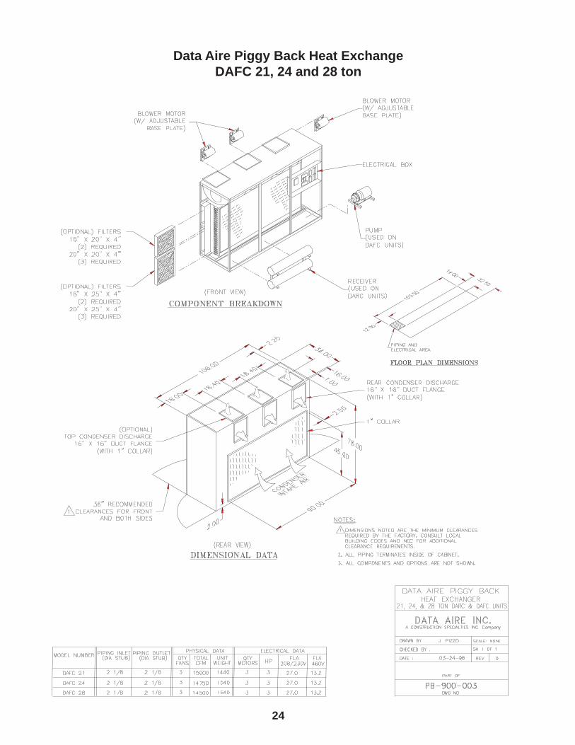
Data Aire Piggy Back Heat ExchangeDAFC 21, 24 and 28 ton

25
Notes_________________________________________________________________________________
_________________________________________________________________________________
_________________________________________________________________________________
_________________________________________________________________________________
_________________________________________________________________________________
_________________________________________________________________________________
_________________________________________________________________________________
_________________________________________________________________________________
_________________________________________________________________________________
_________________________________________________________________________________
_________________________________________________________________________________
_________________________________________________________________________________
_________________________________________________________________________________
_________________________________________________________________________________
_________________________________________________________________________________
_________________________________________________________________________________
_________________________________________________________________________________
_________________________________________________________________________________
_________________________________________________________________________________
_________________________________________________________________________________
_________________________________________________________________________________
_________________________________________________________________________________
_________________________________________________________________________________
_________________________________________________________________________________
_________________________________________________________________________________
_________________________________________________________________________________
_________________________________________________________________________________
_________________________________________________________________________________
_________________________________________________________________________________
_________________________________________________________________________________
_________________________________________________________________________________
_________________________________________________________________________________
_________________________________________________________________________________
_________________________________________________________________________________


230 W. BlueRidge AvenueOrange, CA 92865
800-347-2473
www.dataaire.com e-mail: [email protected] Member of the CS Group of Companies
© 2010 Data Aire, Inc.
FC-SG-IOM 01/06B
Data Aire, Inc. reserves the right to make design changes for the purpose of product improvement or to withdraw any design without notice.