Embed Size (px)
Citation preview
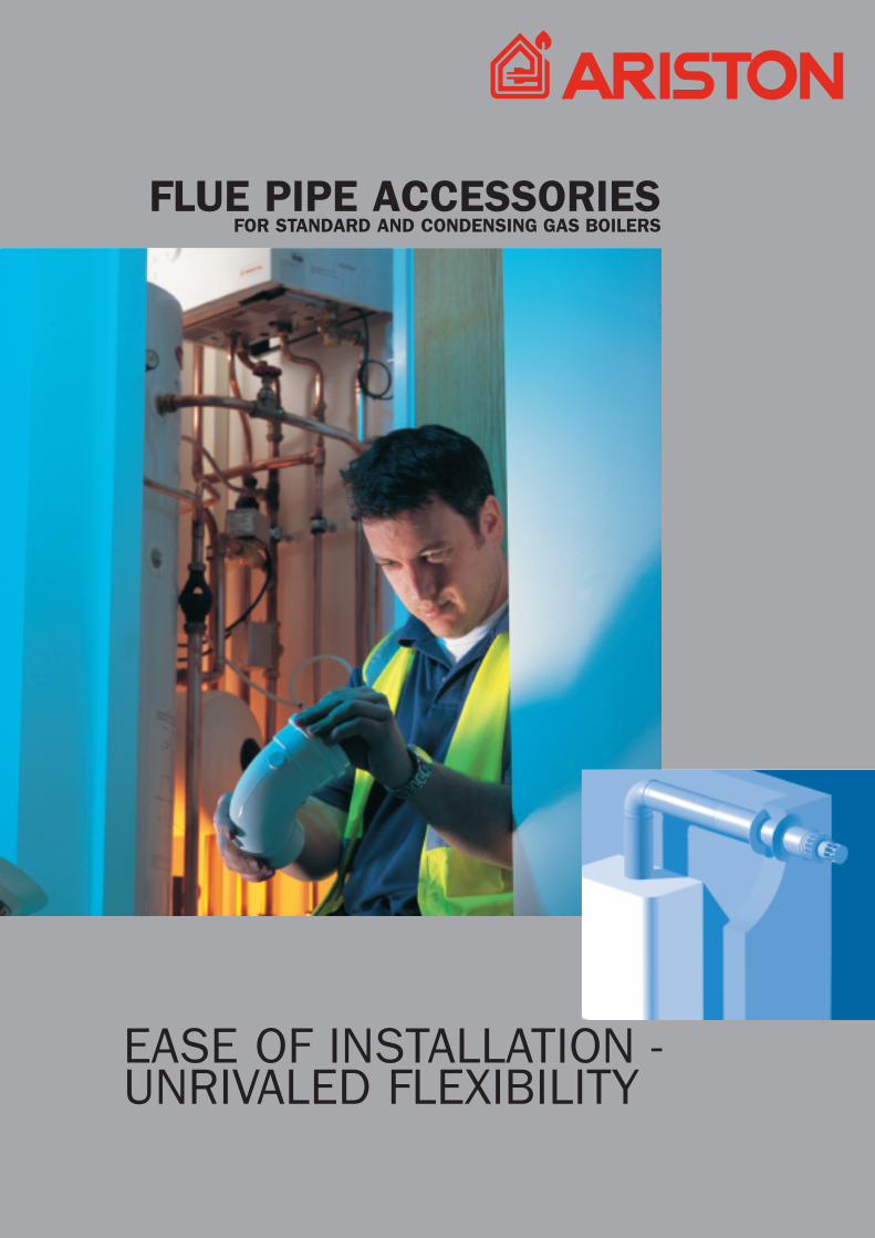
EASE OF INSTALLATION - UNRIVALED FLEXIBILITY
FLUE PIPE ACCESSORIESFOR STANDARD AND CONDENSING GAS BOILERS

INDEX
1.0 GENERAL
1.1 Flue terminal positions1.2 Installation types1.3 Method of calculating the maximum length of flue systems1.4 Installation tips
33
2.0 COAXIAL SYSTEMS
2.1 Air/exhaust systems with coaxial tubes Ø 60/100 (horizontal)2.2 Air/exhaust systems with coaxial tubes Ø 60/100 (vertical)2.3 Air/exhaust systems with coaxial tubes Ø 60/100 (special components)
3.0 TWIN PIPE SYSTEMS
3.1 Air/exhaust systems with separate tubes Ø 80 (horizontal)3.2 Air/exhaust systems with separate tubes Ø 80 (vertical)3.3 Air/exhaust systems with separate tubes Ø 80 (special components)
4.0 CONDENSING SYSTEMS
4.1 Air/exhaust systems with coaxial tubes Ø 60/100 (horizontal)4.2 Air/exhaust systems with separate tubes Ø 80 (horizontal)4.3 Air/exhaust systems (vertical)
8
10
111213
57
151618
9
1.0 GENERAL
3
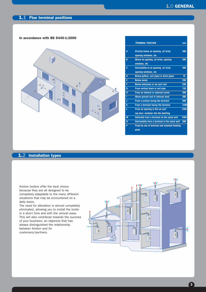
TERMINAL POSITION mm
A Directly below an opening, air brick, 300
opening windows, etc
B Above an opening, air brick, opening 300
windows, etc
C Horizontally to an opening, air brick, 300
opening windows, etc
D Below gutters, soil pipes or drain pipes 75
E Below eaves 200
F Below balconies or car port roof 200
G From vertical drain or soil pipe 150
H From an internal or external corner 300
I Above ground roof or balcony level 300
J From a surface facing the terminal 600
K From a terminal facing the terminal 1200
L From an opening in the car port 1200
(eg door, window) into the dwelling
M Vertically from a terminal on the same wall 1500
N Horizontally from a terminal in the same wall 300
P Fixed by use of terminal and matched flashing -
plate
P
12
3
4
5
6 7
8
Ariston boilers offer the best choicebecause they are all designed to becompletely adaptable to the many differentsituations that may be encountered on adaily basis.The need for alteration is almost completelyeliminated, allowing you to install the boilerin a short time and with the utmost ease.This will also contribute towards the successof your business: an objective that hasalways distinguished the relationshipbetween Ariston and itscustomers/partners.
1.1 Flue terminal positions
1.2 Installation types
In accordance with BS 5440-1:2000
1.0 GENERAL
4
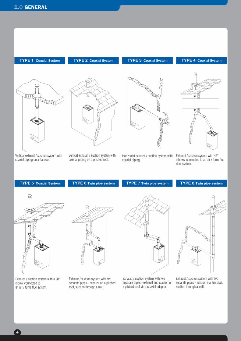
TYPE 1 Coaxial System
TYPE 5 Coaxial System TYPE 6 Twin pipe system TYPE 7 Twin pipe system
TYPE 2 Coaxial System TYPE 3 Coaxial System TYPE 4 Coaxial System
TYPE 8 Twin pipe system
Vertical exhaust / suction system withcoaxial piping on a flat roof.
Vertical exhaust / suction system withcoaxial piping on a pitched roof.
Horizontal exhaust / suction system withcoaxial piping.
Exhaust / suction system with 45°elbows, connected to an air / fume flueduct system.
Exhaust / suction system with a 90°elbow, connected to an air / fume flue system.
Exhaust / suction system with two separate pipes - exhaust on a pitchedroof, suction through a wall.
Exhaust / suction system with twoseparate pipes - exhaust and suction ona pitched roof via a coaxial adaptor.
Exhaust / suction system with two separate pipes - exhaust via flue duct,suction through a wall.

1.0 GENERAL
5
Method of length equivalency.
This is a practical method for sizing the pipes for the intake of combustible air and the discharge of combustion by-products. The principle that forms the basis of the method is that of assigning each component a resistance factorthat corresponds to a length in metres of a rectilinear pipe and where said lengths of pipe share the same cross-sectional dimensions. This length in metres, which in this manual is called length equivalency (Leq), is calculated asfollows:
Where:∆Rcomp. = resistance (loss of pressure) of the component under standard conditions.∆Rpipe = resistance (loss of pressure) of a pipe (with a pre-established diameter) measuring 1 metre under standard
conditions.A standard condition is assumed to be representative of the different operating conditions at play and is anexperimental value for the capacities, fume temperature and air temperature for the various thermal power values.
Leq = [m]∆Rpipe
∆Rcomp.
L* is taken into account in the maximum length.
L1 = 0.2 m +
L2 = 0.5 m +
L3 = 0.8 m +
L4 = 0.75m +
Leq
tot = 2.25m 2.25 < Lmax = 4m
L1
L2
L3
L4
L5
L*
L2L3
L4
L1
L*
L*
L* is taken into account in the maximum length.
L1 = 0.2m +
L2 = 0.5m +
L3 = 1.0m +
L4 = 0.5m +
L5 = 0.5m
Leq
tot = 2.7m 2.7 < Lmax = 4m
Examples of coaxial system calculationsa) Plan the system run;b) Measure the length of the system run;c) Determine the values of the length equivalency for all components;d) Calculate the value of the total length;e) Compare the value with the maximum permissible length.
1.3 Method of calculating the maximum length of flue systems

1.0 GENERAL
6
Examples of twin pipe system calculationsa) Plan the system run;b) Measure the length of the system run;c) Determine the values of the length equivalency for all components;d) Calculate the value of the total length;e) Compare the value with the maximum permissible length.
L* is taken into account in the maximum length.
L1 = 1.3 m +L2 = 1.0 m +L3 = 1.3 m +L4 = 1.0 m +L5 = 1.3 m +L6 = 0.5 m +L7 = 1.0 m +L8 = 1.0 m +L9 = 1.3 m +L10 = 1.0 m +L
eqtot = 10.7m 10.7 < Lmax = 54m
L*
L1L2
L3
L4
L5
L*
L9L6
L7L8
L1
L5
L*
L*
L6
L7
L8
L9
L10
L2
L3
L4L*
L* is taken into account in the maximum length.
L1 = 1,3 m +L2 = 1,0 m +L3 = 1,3 m +L4 = 1,0 m +L5 = 10,0 m +L6 = 1,3 m +L7 = 1,0 m +L8 = 1,3 m +L9 = 1,0 m +L
eqtot = 19,2 m 19,2 < Lmax = 54m
For the maximum length of the flue system, please refer to the table containedwithin the “Flue Pipe Accessories” manual supplied with each boiler.
1.0 GENERAL
7
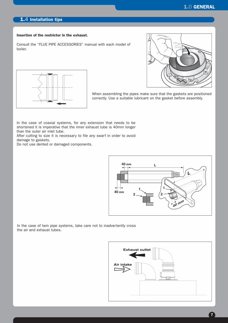
When assembling the pipes make sure that the gaskets are positionedcorrectly. Use a suitable lubricant on the gasket before assembly.
In the case of twin pipe systems, take care not to inadvertently crossthe air and exhaust tubes.
In the case of coaxial systems, for any extension that needs to beshortened it is imperative that the inner exhaust tube is 40mm longerthan the outer air inlet tube.After cutting to size it is necessary to file any swarf in order to avoiddamage to gaskets.Do not use dented or damaged components.
L40 mm
40 mm
L
40 mm
1
21
2
Exhaust outlet
Air intake
Insertion of the restrictor in the exhaust.
Consult the “FLUE PIPE ACCESSORIES” manual with each model ofboiler.
1.4 Installation tips

2.0 COAXIAL SYSTEMS
8
SCHEME
2.1 Air/exhaust systems with coaxial tubes Ø 60/100 (horizontal)
DESCRIPTION OF COMPONENTS QTY CODE Leq
TELESCOPIC HORIZONTAL COAXIAL KIT600mm coaxial kit complete with 90° elbow and terminalPacket with gaskets and fixing screwsCover plate in EPDM
STANDARD HORIZONTAL COAXIAL KIT750mm coaxial kit complete with 90° elbow and terminalPacket with gaskets and fixing screwsCover plate in EPDM
STANDARD HORIZONTAL COAXIAL KIT1000mm coaxial kit complete with 90° elbow and terminalPacket with gaskets and fixing screwsCover plate in EPDM
STANDARD HORIZONTAL COAXIAL KIT WITHOUT ELBOW750mm coaxial kit complete with terminalPacket with gaskets and fixing screwsCover plate in EPDM
90° COAXIAL ELBOW90° coaxial elbowPacket with gaskets and fixing screws
1
1
1
1
1
707067
705785
705958
705783
705787
0.75m
0.75m
1.0m
0.75m
0.8m

2.0 COAXIAL SYSTEMS
9
SCHEME DESCRIPTION OF COMPONENTS QTY CODE Leq
45° COAXIAL ELBOW45° coaxial elbowPacket with gaskets and fixing screws
COAXIAL EXTENSION1000mm coaxial extension with centering springPacket with gaskets and fixing screws
COAXIAL EXTENSION500mm coaxial extension with centering springPacket with gaskets and fixing screws
COAXIAL EXTENSION160mm coaxial extension with centering springPacket with gaskets and fixing screws
2
1
1
1
705788
705786
705790
705812
0.5m
1.0m
0.5m
0.2m
2.2 Air/exhaust systems with coaxial tubes Ø 60/100 (vertical)

2.0 COAXIAL SYSTEMS
10
SCHEME DESCRIPTION OF COMPONENTS QTY CODE Leq
WALL BRACKET KITWall fixing bracket Ø80-120Complete with plugs
3 705778
SCHEME DESCRIPTION OF COMPONENTS QTY CODE Leq
COAXIAL STUB WITH CONDENSATE TRAP160 mm coaxial stub with condensate discharge connectionPacket with gaskets and fixing screws
STANDARD VERTICAL FLUE (BLACK)Vertical flue kit 80/125 complete with 60/100 conical adaptorPacket with gaskets and fixing screws
STANDARD VERTICAL FLUE (TERRACOTTA)
LEAD FLASHING BASE CAP (BLACK)Lead pitched roof flashing with collar
LEAD FLASHING BASE CAP (TERRACOTTA)
VENT BASE CAP FOR FLAT ROOF (BLACK)
1
1
1
1
1
1
705792
705764
705765
705781
705724
704830
0.3m
2.3 Air/exhaust systems with coaxial tubes Ø 60/100 (special components)
3.0 TWIN PIPE SYSTEMS
11
SCHEME DESCRIPTION OF COMPONENTS QTY CODE Leq
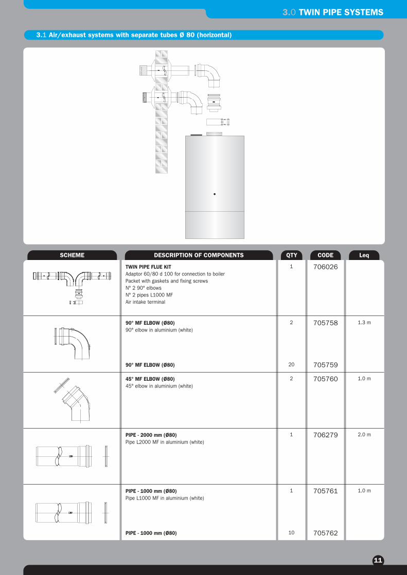
3.1 Air/exhaust systems with separate tubes Ø 80 (horizontal)
TWIN PIPE FLUE KITAdaptor 60/80 d 100 for connection to boilerPacket with gaskets and fixing screwsN° 2 90° elbowsN° 2 pipes L1000 MFAir intake terminal
90° MF ELBOW (Ø80)90° elbow in aluminium (white)
90° MF ELBOW (Ø80)
45° MF ELBOW (Ø80)45° elbow in aluminium (white)
PIPE - 2000 mm (Ø80)Pipe L2000 MF in aluminium (white)
PIPE - 1000 mm (Ø80)Pipe L1000 MF in aluminium (white)
PIPE - 1000 mm (Ø80)
1
2
20
2
1
1
10
706026
705758
705759
705760
706279
705761
705762
1.3 m
1.0 m
2.0 m
1.0 m
3.0 TWIN PIPE SYSTEMS
12
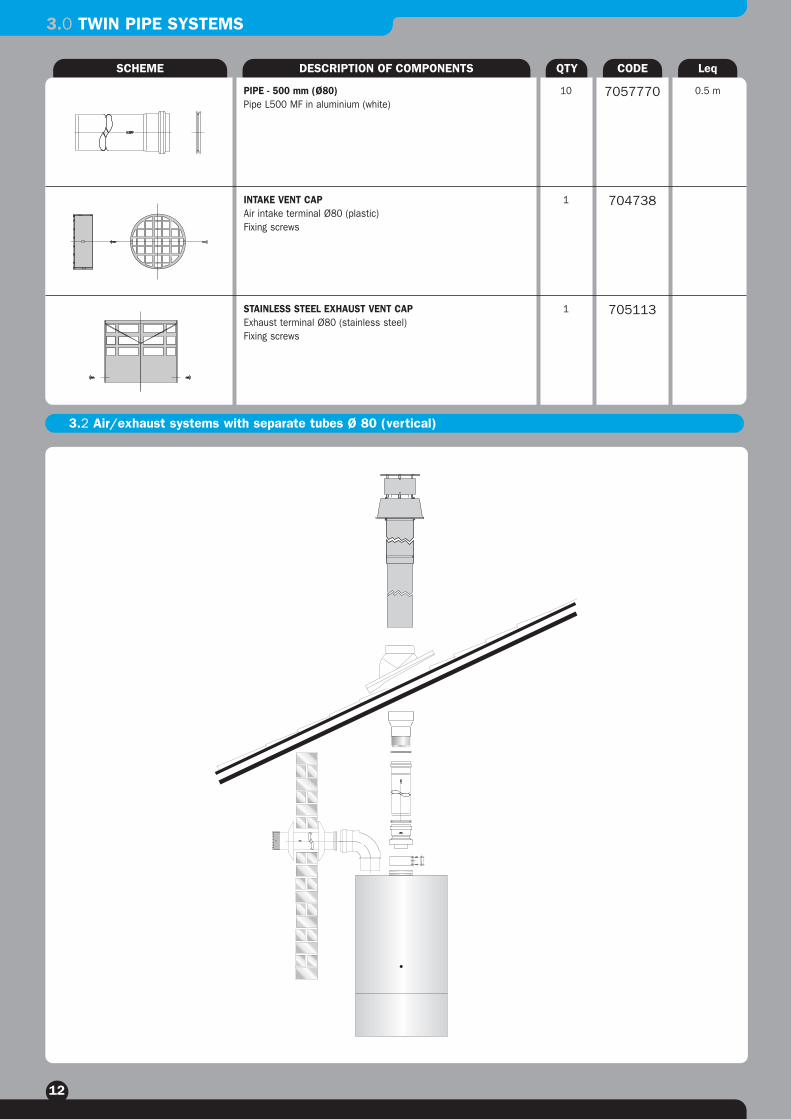
3.2 Air/exhaust systems with separate tubes Ø 80 (vertical)
SCHEME DESCRIPTION OF COMPONENTS QTY CODE Leq
PIPE - 500 mm (Ø80)Pipe L500 MF in aluminium (white)
INTAKE VENT CAPAir intake terminal Ø80 (plastic)Fixing screws
STAINLESS STEEL EXHAUST VENT CAPExhaust terminal Ø80 (stainless steel)Fixing screws
10
1
1
7057770
704738
705113
0.5 m

3.0 TWIN PIPE SYSTEMS
13
SCHEME DESCRIPTION OF COMPONENTS QTY CODE Leq
WALL BRACKET KITWall fixing bracket Ø80-120Complete with plugs
3 705778
SCHEME DESCRIPTION OF COMPONENTS QTY CODE Leq
Adaptor (Ø60/80) FOR TWIN PIPE SYSTEMAdaptor Ø60/80 with Ø100 connection to boilerPacket with gaskets and fixing screws
STUB (Ø80) WITH CONDENSATE COLLECTORPipe L85 MF in aluminium (white) with condensate drain
LEAD FLASHING BASE CAP (BLACK)Lead pitched roof flashing with collar
LEAD FLASHING BASE CAP (TERRACOTTA)
VENT BASE CAP FOR FLAT ROOF (BLACK)
VENT CAP (Ø80) FOR VERTICAL TERMINATIONTerminal Ø80 for flat roofs (black)Fixing screws
PIPE REDUCER (Ø118/80)Adaptor for vertical terminal
STANDARD VERTICAL FLUE (BLACK)Vertical flue kit 80/125 complete with 60/100 conical adaptorPacket with gaskets and fixing screws
STANDARD VERTICAL FLUE (TERRACOTTA)
1
1
1
1
1
1
1
1
705757
705798
705781
705724
704830
705160
707166
705764
705765
0.2m
3.3 Air/exhaust systems with separate tubes Ø 80 (special components)

3.0 TWIN PIPE SYSTEMS
14
SCHEME DESCRIPTION OF COMPONENTS QTY CODE Leq
PIPE BRIDGE (Ø80) Pipe bridge with Ø80/80 M/M inlet and Ø100 M outlet
COVER PLATE (Ø80)EPDM cover plate
ADAPTOR (Ø80) FOR INSULATED PIPESAdaptor Ø80 for connection insulated exhaust pipescomplete with fixing screws
INSULATED PIPE L 1000Pipe Ø80/100 L 1000 insulatedPacket with gaskets and fixing screws
90° INSULATED ELBOW (Ø80)90° insulated elbow Ø80/100 Packet with gaskets and fixing screws
45° INSULATED ELBOW (Ø80)45° insulated elbow Ø80/100 Packet with gaskets and fixing screw
1
2
1
1
1
1
705767
705784
705769
705771
705772
705773
10m
0.2m
1m
1.3m
1m
4.0 CONDENSING SYSTEMS
15
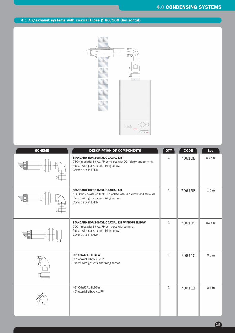
SCHEME
4.1 Air/exhaust systems with coaxial tubes Ø 60/100 (horizontal)
DESCRIPTION OF COMPONENTS QTY CODE Leq
STANDARD HORIZONTAL COAXIAL KIT750mm coaxial kit AL/PP complete with 90° elbow and terminalPacket with gaskets and fixing screwsCover plate in EPDM
STANDARD HORIZONTAL COAXIAL KIT1000mm coaxial kit AL/PP complete with 90° elbow and terminalPacket with gaskets and fixing screwsCover plate in EPDM
STANDARD HORIZONTAL COAXIAL KIT WITHOUT ELBOW750mm coaxial kit AL/PP complete with terminalPacket with gaskets and fixing screwsCover plate in EPDM
90° COAXIAL ELBOW90° coaxial elbow AL/PPPacket with gaskets and fixing screws
45° COAXIAL ELBOW45° coaxial elbow AL/PP
1
1
1
1
2
706108
706138
706109
706110
706111
0.75 m
1.0 m
0.75 m
0.8 m
0.5 m

4.0 CONDENSING SYSTEMS
16
SCHEME DESCRIPTION OF COMPONENTS QTY CODE Leq
COAXIAL EXTENSION 1000 mmCoaxial extension 1000mm (Ø60 M/F) AL/PPwith centering spring
COAXIAL EXTENSION 500 mmCoaxial extension 500mm (Ø60 M/F) AL/PPwith centering spring
COAXIAL EXTENSION (INSPECTION)Coaxial extension 350mm AL/PPwith centering spring and inspection hatch
WALL BRACKET KITWall fixing bracket Ø80-120Complete with plugs
1
1
1
3
706112
706113
706114
705778
1.0 m
0.5m
0.4m
4.2 Air/exhaust systems with separate tubes Ø 80 (horizontal)
4.0 CONDENSING SYSTEMS
17
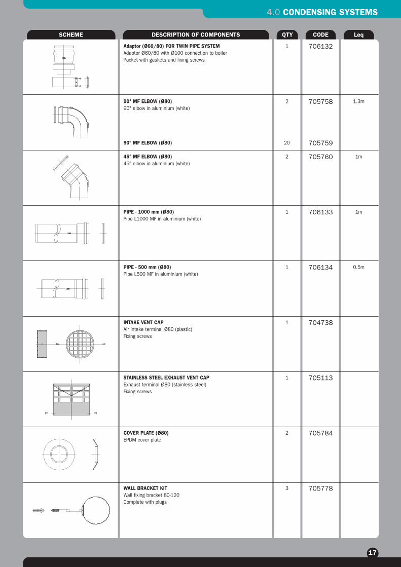
SCHEME DESCRIPTION OF COMPONENTS QTY CODE Leq
Adaptor (Ø60/80) FOR TWIN PIPE SYSTEMAdaptor Ø60/80 with Ø100 connection to boilerPacket with gaskets and fixing screws
90° MF ELBOW (Ø80)90° elbow in aluminium (white)
90° MF ELBOW (Ø80)
45° MF ELBOW (Ø80)45° elbow in aluminium (white)
PIPE - 1000 mm (Ø80)Pipe L1000 MF in aluminium (white)
PIPE - 500 mm (Ø80)Pipe L500 MF in aluminium (white)
INTAKE VENT CAPAir intake terminal Ø80 (plastic)Fixing screws
STAINLESS STEEL EXHAUST VENT CAPExhaust terminal Ø80 (stainless steel)Fixing screws
COVER PLATE (Ø80)EPDM cover plate
WALL BRACKET KITWall fixing bracket 80-120Complete with plugs
1
2
20
2
1
1
1
1
2
3
1.3m
1m
1m
0.5m
706132
705758
705759
705760
706133
706134
704738
705113
705784
705778
4.0 CONDENSING SYSTEMS
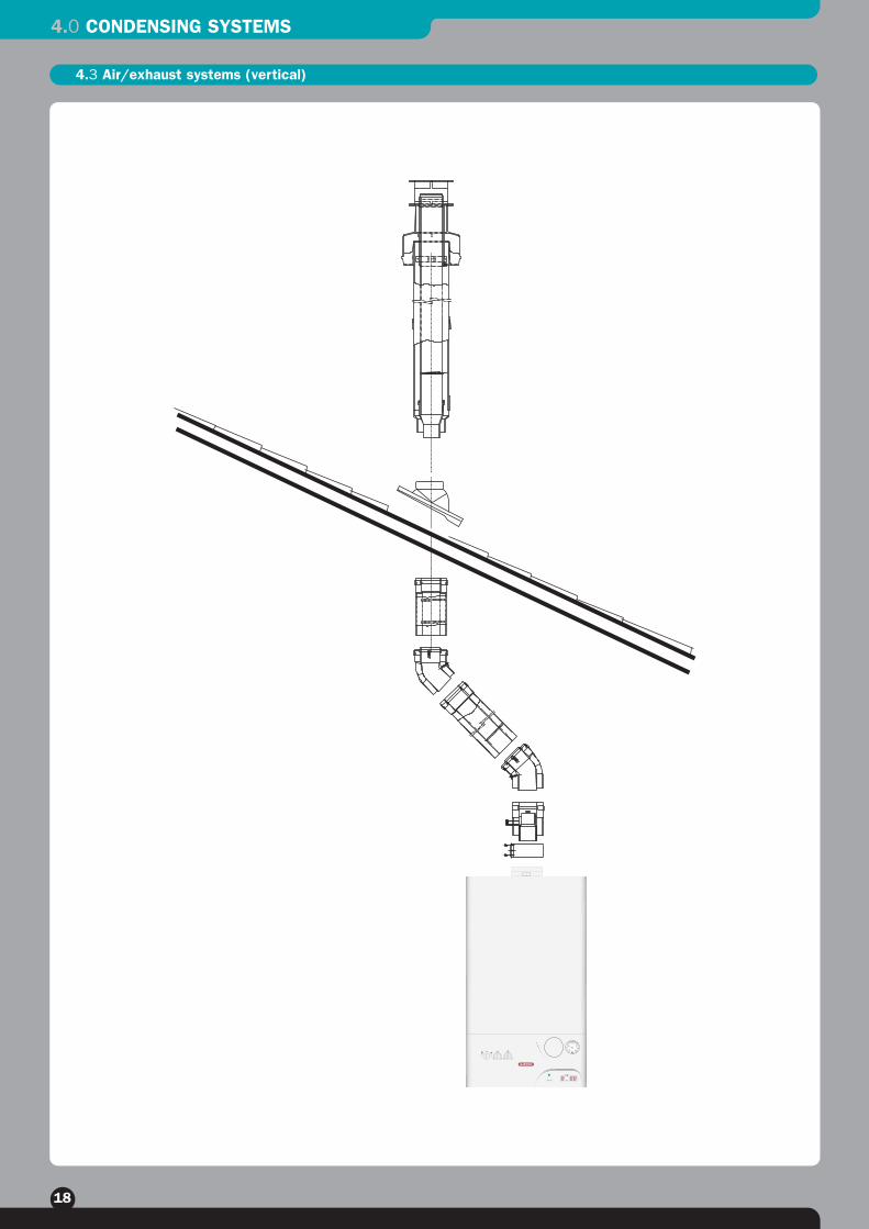
18
4.3 Air/exhaust systems (vertical)

4.0 CONDENSING SYSTEMS
19
SCHEME DESCRIPTION OF COMPONENTS QTY CODE Leq
COAXIAL STUB WITH CONDENSATE TRAP160 mm coaxial stub with condensate discharge connectionPacket with gaskets and fixing screws
LEAD FLASHING BASE CAP (BLACK)Lead pitched roof flashing with collar
LEAD FLASHING BASE CAP (TERRACOTTA)
VENT BASE CAP FOR FLAT ROOF (BLACK)
VENT CAP (Ø80) FOR VERTICAL TERMINATIONTerminal Ø80 for flat roofs (black)Fixing screws
STANDARD VERTICAL FLUE (BLACK)Vertical flue kit 80/125 complete with 60/100 conical adaptorPacket with gaskets and fixing screws
STANDARD VERTICAL FLUE (TERRACOTTA)
1
1
1
1
1
1
1
1
706125
706065
706067
706069
705160
706116
706117
0.2m
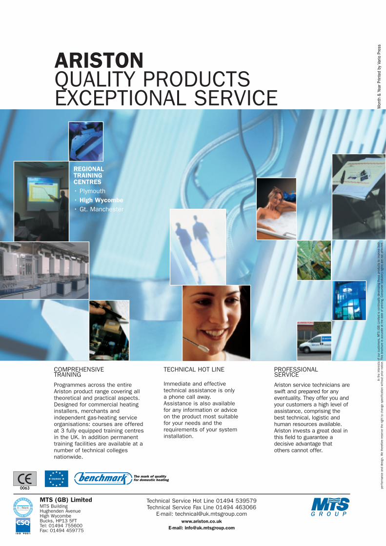
ARISTONQUALITY PRODUCTSEXCEPTIONAL SERVICE
REGIONALTRAININGCENTRES• Plymouth• High Wycombe• Gt. Manchester
COMPREHENSIVETRAINING
Programmes across the entireAriston product range covering alltheoretical and practical aspects.Designed for commercial heatinginstallers, merchants andindependent gas-heating serviceorganisations: courses are offeredat 3 fully equipped training centresin the UK. In addition permanenttraining facilities are available at anumber of technical collegesnationwide.
TECHNICAL HOT LINE
Immediate and effectivetechnical assistance is onlya phone call away.Assistance is also availablefor any information or adviceon the product most suitablefor your needs and therequirements of your systeminstallation.
PROFESSIONALSERVICE
Ariston service technicians areswift and prepared for anyeventuality. They offer you andyour customers a high level ofassistance, comprising thebest technical, logistic andhuman resources available.Ariston invests a great deal inthis field to guarantee adecisive advantage that others cannot offer.
MTS (GB) LimitedMTS BuildingHughenden AvenueHigh WycombeBucks, HP13 5FTTel: 01494 755600Fax: 01494 459775
Technical Service Hot Line 01494 539579Technical Service Fax Line 01494 463066
E-mail: [email protected]
E-mail: [email protected]
In th
e in
tere
sts
of o
ur c
usto
mer
s, M
TS (G
B) L
imite
d is
con
tinua
lly d
evel
opin
g th
ese
prod
ucts
to im
prov
e bo
thpe
rfor
man
ce a
nd d
esig
n. W
e th
eref
ore
rese
rve
the
right
to c
hang
e sp
ecifi
catio
n w
ithou
t prio
r not
ice.
Thi
s br
ochu
re is
acc
urat
e at
the
date
of p
rintin
g. C
onsu
mer
sta
tuto
ry ri
ghts
are
not
aff
ecte
d.
0063
Mon
th &
Yea
r Prin
ted
by V
ario
Pre
ss