Embed Size (px)
Citation preview

FLOWTITE GRP Pipe Systemsfor Bridge- and Tunnel Drainage
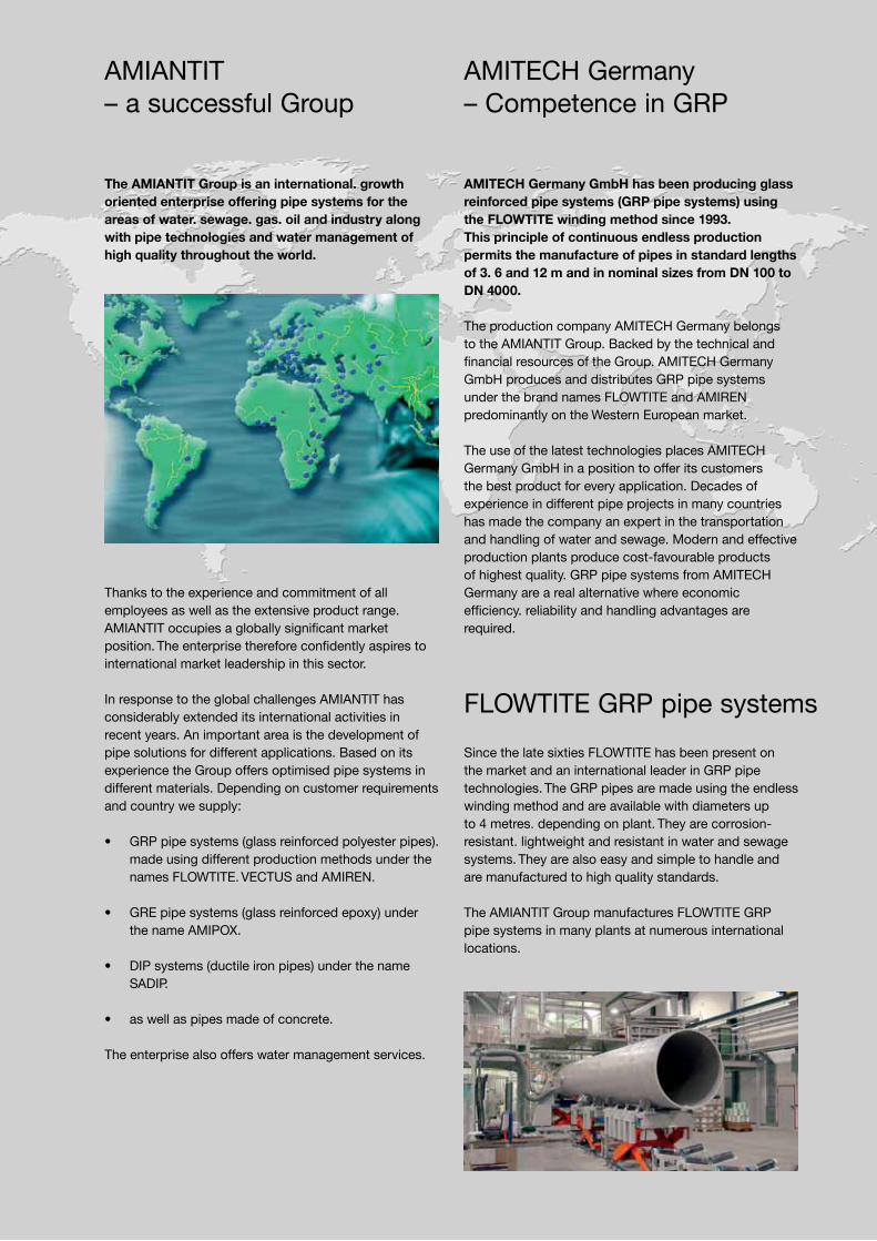
The AMIANTIT Group is an international. growth oriented enterprise offering pipe systems for the areas of water. sewage. gas. oil and industry along with pipe technologies and water management of high quality throughout the world.
Thanks to the experience and commitment of all employees as well as the extensive product range. AMIANTIT occupies a globally significant market position. The enterprise therefore confidently aspires to international market leadership in this sector.
In response to the global challenges AMIANTIT has considerably extended its international activities in recent years. An important area is the development of pipe solutions for different applications. Based on its experience the Group offers optimised pipe systems in different materials. Depending on customer requirements and country we supply:
• GRP pipe systems (glass reinforced polyester pipes). made using different production methods under the names FLOWTITE. VECTUS and AMIREN.
• GRE pipe systems (glass reinforced epoxy) under the name AMIPOX.
• DIP systems (ductile iron pipes) under the name SADIP.
• as well as pipes made of concrete.
The enterprise also offers water management services.
AMIANTIT – a successful Group
AMITECH Germany– Competence in GRP
AMITECH Germany GmbH has been producing glass reinforced pipe systems (GRP pipe systems) using the FLOWTITE winding method since 1993. This principle of continuous endless production permits the manufacture of pipes in standard lengths of 3. 6 and 12 m and in nominal sizes from DN 100 to DN 4000.
The production company AMITECH Germany belongs to the AMIANTIT Group. Backed by the technical and financial resources of the Group. AMITECH Germany GmbH produces and distributes GRP pipe systems under the brand names FLOWTITE and AMIREN predominantly on the Western European market.
The use of the latest technologies places AMITECH Germany GmbH in a position to offer its customers the best product for every application. Decades of experience in different pipe projects in many countries has made the company an expert in the transportation and handling of water and sewage. Modern and effective production plants produce cost-favourable products of highest quality. GRP pipe systems from AMITECH Germany are a real alternative where economic efficiency. reliability and handling advantages are required.
Since the late sixties FLOWTITE has been present on the market and an international leader in GRP pipe technologies. The GRP pipes are made using the endless winding method and are available with diameters up to 4 metres. depending on plant. They are corrosion-resistant. lightweight and resistant in water and sewage systems. They are also easy and simple to handle and are manufactured to high quality standards.
The AMIANTIT Group manufactures FLOWTITE GRP pipe systems in many plants at numerous international locations.
FLOWTITE GRP pipe systems

Inhaltsverzeichnis
1 Introduction ....................................................... 4
2 Construction and Requirements .................... 42.1 Requirements ...................................................... 42.2 Construction of a bridge drainage system ......... 42.3 Bridge Dewatering Systems ............................... 52.4 Tunnel Drainage Systems ................................... 5
3 FLOWTITE GRP Pipes ....................................... 6
4 Product Advantages ......................................... 7
5 Product Range .................................................. 95.1 Product Range STANDARD ................................ 95.1.1 Pipes ................................................................... 95.1.2 Couplings .......................................................... 105.1.3 Connectors ....................................................... 105.1.4 Bends ................................................................ 105.1.5 Branches 45� .....................................................115.1.6 Eccentric reducers ............................................ 125.1.7 Saddle pieces ................................................... 135.1.8 Flexible Pipe Connections ................................ 145.1.9 Down Spout Supports ...................................... 145.1.10 End Caps .......................................................... 145.1.11 Pipe suspension systems ................................. 14
5.2 Product Range FLAME RETARDANT acc. to ZTV-ING ................................................ 155.2.1 Pipes ................................................................. 155.2.2 Connectors ....................................................... 155.2.3 Bends ................................................................ 165.2.4 Eccentric Reducers .......................................... 165.2.5 Branches 45� .................................................... 175.2.6 Saddle pieces ................................................... 185.2.7 Flexible Pipe Connections ................................ 195.2.8 Down Spout Supports ...................................... 195.2.9 End Caps .......................................................... 195.2.10 Pipe suspension systems ................................. 19
6 Installation ....................................................... 207 Services ........................................................... 218 References....................................................... 22

4
Bridges and Tunnels are an essential but sensible part of every street network.
They allow best possible routing by crossing mountains. valleys and rivers. But their open construction makes them vulnerable for damages and corrosion.
Only adequate structural measures help to prevent major damages and corrosion. Bridge and Tunnel dewateringis one of these measures. The installation and functionality of an appropriate dewatering system is often crucial for the durability of bridges and tunnels. Providing sage water drainage. effective dewatering systems guarantee safe driving as well as corrosion prevention. even at extreme weather conditions.
1 Introduction 2 Construction and Requirements
The most common damage to bridges is caused quite often by non effective. defect or wrongly installed drainage systems. Another cause might be in the wrong material choice for the individual components of the drainage system.
2.1 Requirements
Bridge and Tunnel drainage pipelines must be resistant to external influences (spreading salts and acidic exhaust gases). vibrations and high temperature fluctuations. In addition. they need to be stable in form. easy to install. robust and of a long service life.
They should not impair the harmonious appearance of the constructions and are therefore usually adapted to the construction. Coloured designs with a long life-cycle are standard for this kind of application.
2.2 Construction of a bridge drainage system
A complete. functional drainage system consists of:
• the inlet system (“bridge outlet“)
• the pipeline system with mountings and fixings and
• the drainage system
The water drained from the bridge is fed into a draw pit and passed on into a storage reservoir.
5
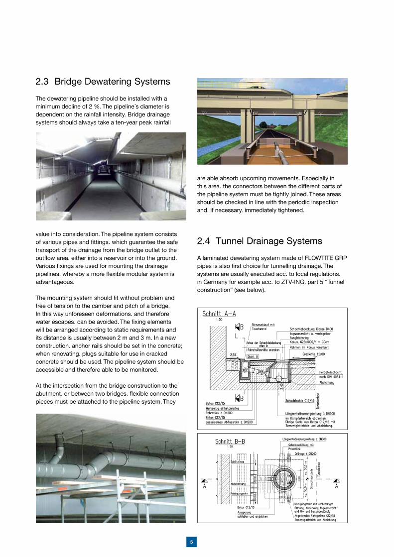
2.3 Bridge Dewatering Systems
The dewatering pipeline should be installed with a minimum decline of 2 %. The pipeline´s diameter is dependent on the rainfall intensity. Bridge drainage systems should always take a ten-year peak rainfall
value into consideration. The pipeline system consists of various pipes and fittings. which guarantee the safe transport of the drainage from the bridge outlet to the outflow area. either into a reservoir or into the ground. Various fixings are used for mounting the drainage pipelines. whereby a more flexible modular system is advantageous.
The mounting system should fit without problem and free of tension to the camber and pitch of a bridge. In this way unforeseen deformations. and therefore water escapes. can be avoided. The fixing elements will be arranged according to static requirements and its distance is usually between 2 m and 3 m. In a new construction. anchor rails should be set in the concrete; when renovating. plugs suitable for use in cracked concrete should be used. The pipeline system should be accessible and therefore able to be monitored.
At the intersection from the bridge construction to the abutment. or between two bridges. flexible connection pieces must be attached to the pipeline system. They
are able absorb upcoming movements. Especially in this area. the connectors between the different parts of the pipeline system must be tightly joined. These areas should be checked in line with the periodic inspection and. if necessary. immediately tightened.
2.4 Tunnel Drainage Systems
A laminated dewatering system made of FLOWTITE GRP pipes is also first choice for tunnelling drainage. The systems are usually executed acc. to local regulations. in Germany for example acc. to ZTV-ING. part 5 “Tunnel construction” (see below).
6
FLOWTITE GRP pipeline systems are the perfect choice for the use in bridge and tunnel dewatering systems. Due to the raw materials used and the pipe wall build-up resulting in a multi-layer design. the use of these pipes guarantees long service life by being rust-free. as well as optimum safety through fast water drainage.
3 FLOWTITE GRP Pipes
The basic raw materials used in the FLOWTITE pipe´s manufacturing are resin. fibreglass and silica sand. FLOWTITE GRP pipes smaller than 300 mm are discontinuously manufactured with the same wall build-up than the bigger diameters. FLOWTITE pipes bigger than DN 300 are manufactured using the continuous advancing mandrel process. This process allows the use of continuous glass fibre reinforcements in the
circumferential direction and creates a very dense laminate that maximizes the contribution from all three basic raw materials. Both continuous glass fibre rovings and choppable roving are incorporated for high hoop strength and axial reinforcement.
A sand fortifier is used to provide increased stiffness by adding extra thickness. placed near the neutral axis in the core.
With the FLOWTITE dual resin delivery system. the equipment has the capability of applying a special inner resin liner for severe corrosive applications while using a less costly resin for the structural and outer portion of the laminate.Taking advantage of the winding process. other materials such as veils or flame retardant additives can be added used to enhance the
abrasion or fire resistance of the pipe. The pipes offer a high and consistent product quality worldwide and reliable product that complies to stringent performance standards such as AWWA. ASTM. DIN. EN. etc.
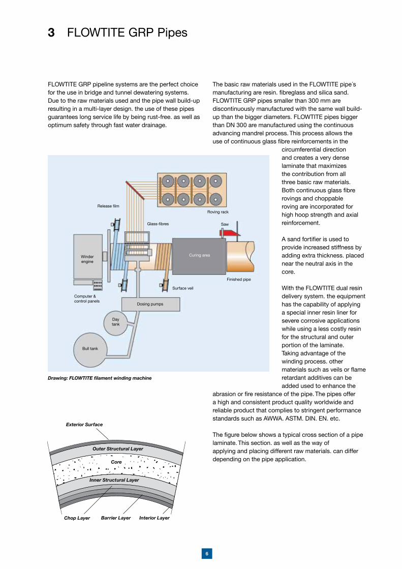
The figure below shows a typical cross section of a pipe laminate. This section. as well as the way ofapplying and placing different raw materials. can differ depending on the pipe application.
Exterior Surface
Outer Structural Layer
Inner Structural Layer
Core
Chop Layer Interior LayerBarrier Layer
Drawing: FLOWTITE filament winding machine
Release film
Winderengine
Surface veil
Dosing pumps
Curing area
Finished pipe
Roving rack
Saw
Daytank
Bull tank
Computer &control panels
Glass-fibres
7
High Chemical ResistanceBy choosing optimum resin. FLOWTITE GRP pipes can be used for almost all types of liquid. The ideal selection takes the chemical properties of the liquid and the operating temperature into consideration.
Low Thermal ExpansionThe thermal expansion coefficient for FLOWTITE GRP pipes is approximately 24 – 30 x 10-6 1/K.Thermal expansion is therefore small and can be absorbed by couplings and joints.
Excellent UV ResistanceThere is no evidence that UV exposure is a factorthat affects the long-term service life of FLOWTITE pipes. In their long and comprehensive experience in the Middle East in damp and desert conditions. in Scandinavia in various dark and cold winters. as well as in more than 30 years of above ground pipe laying. FLOWTITE has not found any indications of any structural effects of radiation on its GRP pipes.
No E – PotentialGRP pipes are made of a non-metallic material resulting in a lack of electrochemical corrosion. Stray currents from train lines or overhead cables do not attack the pipes.
4 Product Advantages
FLOWTITE Technology has been able to bring a product to the market that provides a low cost. long-term piping solution to customers around the world.
The long list of features and benefits add up to provide the optimum installed and life cycle cost system and the unique combination of mechanical and chemical properties proves itself here in a special way.
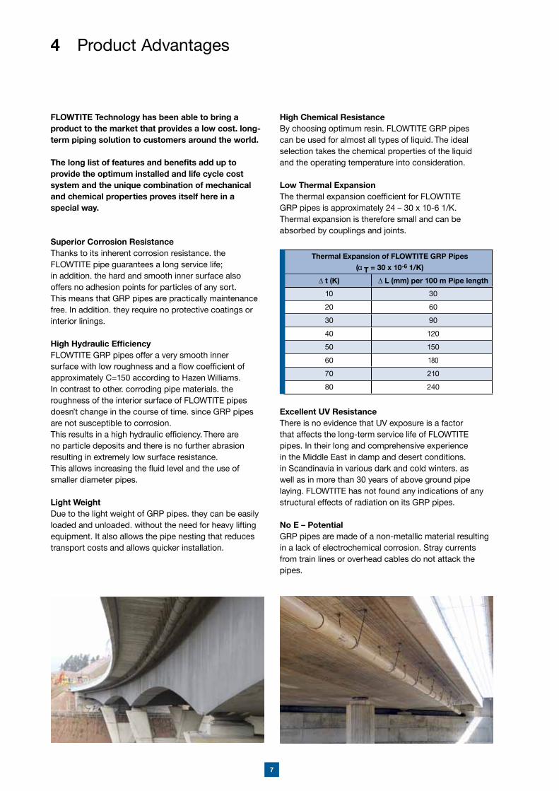
Superior Corrosion ResistanceThanks to its inherent corrosion resistance. the FLOWTITE pipe guarantees a long service life; in addition. the hard and smooth inner surface also offers no adhesion points for particles of any sort. This means that GRP pipes are practically maintenance free. In addition. they require no protective coatings or interior linings.
High Hydraulic EfficiencyFLOWTITE GRP pipes offer a very smooth inner surface with low roughness and a flow coefficient of approximately C=150 according to Hazen Williams.In contrast to other. corroding pipe materials. the roughness of the interior surface of FLOWTITE pipes doesn’t change in the course of time. since GRP pipes are not susceptible to corrosion.This results in a high hydraulic efficiency. There are no particle deposits and there is no further abrasion resulting in extremely low surface resistance.This allows increasing the fluid level and the use of smaller diameter pipes.
Light WeightDue to the light weight of GRP pipes. they can be easily loaded and unloaded. without the need for heavy lifting equipment. It also allows the pipe nesting that reduces transport costs and allows quicker installation.
Thermal Expansion of FLOWTITE GRP Pipes ( T = 30 x 10-6 1/K)
t (K) L (mm) per 100 m Pipe length
10 30
20 60
30 90
40 120
50 150
60 180
70 210
80 240
8
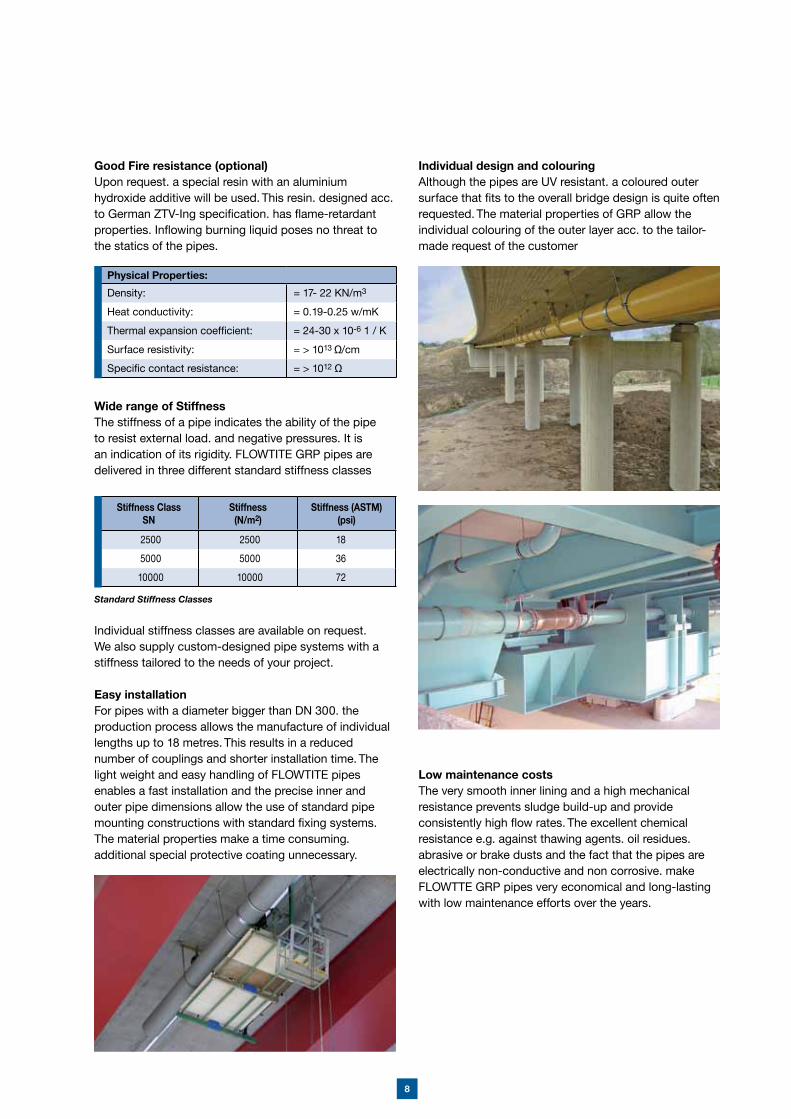
Individual design and colouringAlthough the pipes are UV resistant. a coloured outer surface that fits to the overall bridge design is quite often requested. The material properties of GRP allow the individual colouring of the outer layer acc. to the tailor-made request of the customer
Low maintenance costsThe very smooth inner lining and a high mechanical resistance prevents sludge build-up and provide consistently high flow rates. The excellent chemical resistance e.g. against thawing agents. oil residues. abrasive or brake dusts and the fact that the pipes are electrically non-conductive and non corrosive. make FLOWTTE GRP pipes very economical and long-lasting with low maintenance efforts over the years.
Good Fire resistance (optional)Upon request. a special resin with an aluminium hydroxide additive will be used. This resin. designed acc. to German ZTV-Ing specification. has flame-retardant properties. Inflowing burning liquid poses no threat to the statics of the pipes.
Wide range of Stiffness The stiffness of a pipe indicates the ability of the pipe to resist external load. and negative pressures. It is an indication of its rigidity. FLOWTITE GRP pipes are delivered in three different standard stiffness classes
Individual stiffness classes are available on request. We also supply custom-designed pipe systems with a stiffness tailored to the needs of your project.
Easy installationFor pipes with a diameter bigger than DN 300. the production process allows the manufacture of individual lengths up to 18 metres. This results in a reduced number of couplings and shorter installation time. The light weight and easy handling of FLOWTITE pipes enables a fast installation and the precise inner and outer pipe dimensions allow the use of standard pipe mounting constructions with standard fixing systems. The material properties make a time consuming. additional special protective coating unnecessary.
Stiffness ClassSN
Stiffness(N/m2)
Stiffness (ASTM) (psi)
2500 2500 18
5000 5000 36
10000 10000 72
Standard Stiffness Classes
Physical Properties:
Density: = 17- 22 KN/m3
Heat conductivity: = 0.19-0.25 w/mK
Thermal expansion coefficient: = 24-30 x 10-6 1 / K
Surface resistivity: = > 1013 /cm
Specific contact resistance: = > 1012
9
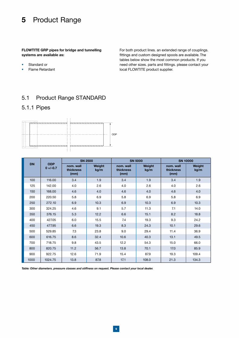
5.1 Product Range STANDARD
5.1.1 Pipes
5 Product Range
FLOWTITE GRP pipes for bridge and tunnelling systems are available as:
• Standard or• Flame Retardant
For both product lines. an extended range of couplings. fittings and custom designed spools are available. The tables below show the most common products. If you need other sizes. parts and fittings. please contact your local FLOWTITE product supplier.
ODP
Table: Other diameters. pressure classes and stiffness on request. Please contact your local dealer.
DN ODP0 +/-0.7
SN 2500 SN 5000 SN 10000
nom. wall thickness
(mm)
Weightkg/m
nom. wall thickness
(mm)
Weightkg/m
nom. wall thickness
(mm)
Weightkg/m
100 116.00 3.4 1.9 3.4 1.9 3.4 1.9
125 142.00 4.0 2.6 4.0 2.6 4.0 2.6
150 168.00 4.6 4.0 4.6 4.0 4.6 4.0
200 220.50 5.8 6.9 5.8 6.9 5.8 6.9
250 272.10 6.9 10.3 6.9 10.3 6.9 10.3
300 324.25 4.6 9.1 5.7 11.3 7.1 14.0
350 376.15 5.3 12.2 6.6 15.1 8.2 18.8
400 427.05 6.0 15.5 7.4 19.3 9.3 24.2
450 477.95 6.6 19.3 8.3 24.3 10.1 29.6
500 529.85 7.3 23.8 9.0 29.4 11.4 36.9
600 616.75 8.6 32.4 10.6 40.3 13.1 49.5
700 718.75 9.8 43.5 12.2 54.3 15.0 66.0
800 820.75 11.2 56.7 13.8 70.1 17.0 85.9
900 922.75 12.6 71.9 15.4 87.9 19.3 109.4
1000 1024.75 13.8 87.8 17.1 108.0 21.3 134.3
10
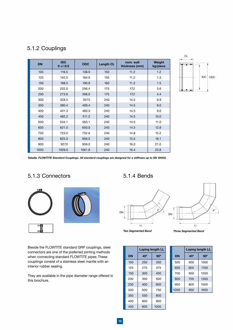
Tabelle: FLOWTITE Standard Couplings. All standard couplings are designed for a stiffness up to SN 10000.
5.1.2 Couplings
Beside the FLOWTITE standard GRP couplings, steel connectors are one of the preferred jointing methods when connecting standard FLOWTITE pipes. These couplings consist of a stainless steel mantle with an interior rubber sealing.
They are available in the pipe diameter range offered in this brochure.
5.1.3 Connectors 5.1.4 Bends
Two Segmented Bend Three Segmented Bend
LLLL
Laying length LL
DN 45� 90�
100 250 350
125 275 375
150 300 400
200 350 500
250 400 600
300 500 750
350 550 800
400 600 900
450 600 1000
Laying length LL
DN 45� 90�
500 650 1050
600 600 1100
700 650 1200
800 700 1350
900 800 1500
1000 850 1650
DN IDC0 +/-0.5 ODC Length CL nom. wall
thickness (mm)Weight
kg/piece
100 116.5 138.9 150 11.2 1.2
125 142.5 164.9 155 11.2 1.3
150 168.5 190.9 160 11.2 1.5
200 222.0 256.4 175 17.2 3.6
250 273.6 308.0 175 17.2 4.4
300 328.5 357.5 240 14.5 6.9
350 380.4 409.4 240 14.5 8.0
400 431.3 460.3 240 14.5 9.0
450 482.2 511.2 240 14.5 10.0
500 534.1 563.1 240 14.5 11.0
600 621.0 650.0 240 14.5 12.8
700 723.0 752.6 240 14.8 15.2
800 825.0 856.0 240 15.5 18.1
900 927.0 959.0 240 16.0 21.0
1000 1029.0 1061.8 240 16.4 23.8
CL
IDC ODC
11
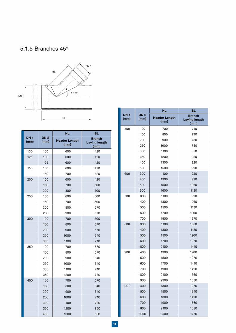
5.1.5 Branches 45�
DN 1 (mm)
DN 2 (mm)
HL BL
Header Length(mm)
Branch Laying length
(mm)
100 100 600 420
125 100 600 420
125 600 420
150 100 600 420
150 700 420
200 100 600 420
150 700 500
200 800 500
250 100 600 500
150 700 500
200 800 570
250 900 570
300 100 700 500
150 800 570
200 900 570
250 1000 640
300 1100 710
350 100 700 570
150 800 570
200 900 640
250 1000 640
300 1100 710
350 1200 780
400 100 700 570
150 800 640
200 900 640
250 1000 710
300 1100 780
350 1200 850
400 1300 850
DN 1 (mm)
DN 2 (mm)
HL BL
Header Length(mm)
Branch Laying length
(mm)
500 100 700 710
150 800 710
200 900 780
250 1000 780
300 1100 850
350 1200 920
400 1300 920
500 1500 990
600 300 1100 920
400 1300 990
500 1500 1060
600 1600 1130
700 300 1100 990
400 1300 1060
500 1500 1130
600 1700 1200
700 1900 1270
800 300 1100 1060
400 1300 1130
500 1500 1200
600 1700 1270
800 2100 1410
900 400 1300 1200
500 1500 1270
600 1700 1410
700 1900 1490
800 2100 1560
900 2300 1630
1000 400 1300 1270
500 1500 1340
600 1800 1490
700 1900 1560
800 2100 1630
1000 2500 1770
HL
BL
DN 1
DN 2
12
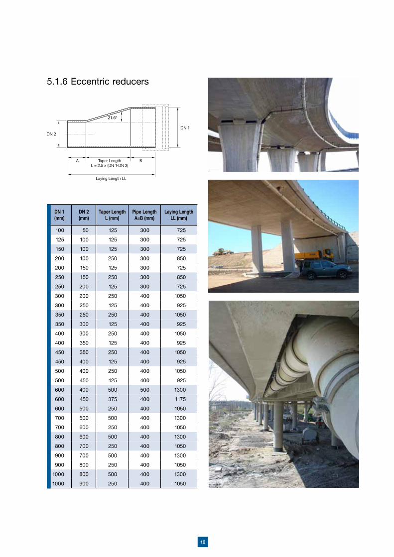
5.1.6 Eccentric reducers
DN 1 (mm)
DN 2 (mm)
Taper LengthL (mm)
Pipe LengthA=B (mm)
Laying LengthLL (mm)
100 50 125 300 725
125 100 125 300 725
150 100 125 300 725
200 100 250 300 850
200 150 125 300 725
250 150 250 300 850
250 200 125 300 725
300 200 250 400 1050
300 250 125 400 925
350 250 250 400 1050
350 300 125 400 925
400 300 250 400 1050
400 350 125 400 925
450 350 250 400 1050
450 400 125 400 925
500 400 250 400 1050
500 450 125 400 925
600 400 500 500 1300
600 450 375 400 1175
600 500 250 400 1050
700 500 500 400 1300
700 600 250 400 1050
800 600 500 400 1300
800 700 250 400 1050
900 700 500 400 1300
900 800 250 400 1050
1000 800 500 400 1300
1000 900 250 400 1050
Taper LengthL = 2.5 x (DN 1-DN 2)
Laying Length LL
13
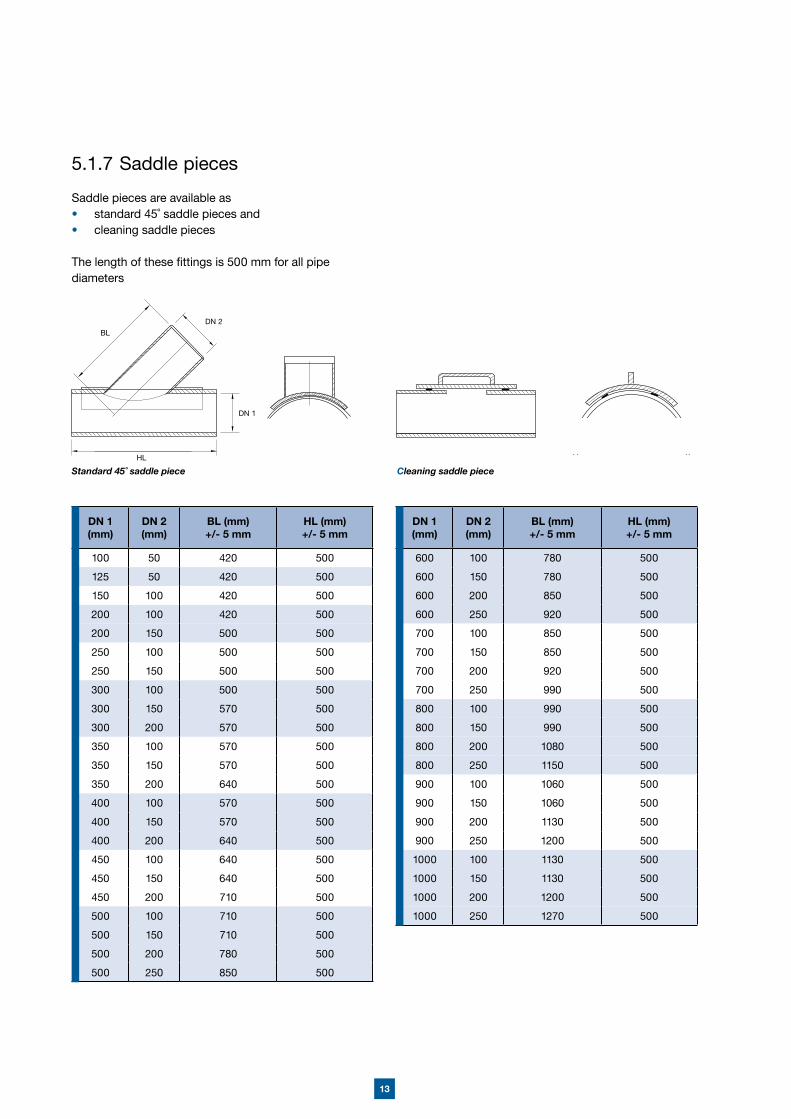
5.1.7 Saddle pieces
Saddle pieces are available as• standard 45˚ saddle pieces and • cleaning saddle pieces
The length of these fittings is 500 mm for all pipe diameters
Standard 45˚ saddle piece HL
DN 1
DN 2
Cleaning saddle piece
BL
DN 1 (mm)
DN 2 (mm)
BL (mm)+/- 5 mm
HL (mm)+/- 5 mm
600 100 780 500
600 150 780 500
600 200 850 500
600 250 920 500
700 100 850 500
700 150 850 500
700 200 920 500
700 250 990 500
800 100 990 500
800 150 990 500
800 200 1080 500
800 250 1150 500
900 100 1060 500
900 150 1060 500
900 200 1130 500
900 250 1200 500
1000 100 1130 500
1000 150 1130 500
1000 200 1200 500
1000 250 1270 500
DN 1 (mm)
DN 2 (mm)
BL (mm)+/- 5 mm
HL (mm)+/- 5 mm
100 50 420 500
125 50 420 500
150 100 420 500
200 100 420 500
200 150 500 500
250 100 500 500
250 150 500 500
300 100 500 500
300 150 570 500
300 200 570 500
350 100 570 500
350 150 570 500
350 200 640 500
400 100 570 500
400 150 570 500
400 200 640 500
450 100 640 500
450 150 640 500
450 200 710 500
500 100 710 500
500 150 710 500
500 200 780 500
500 250 850 500
14
5.1.9 Down Spout Supports
Down spout supports are available for diameters between DN 100 and DN 1000 with a length of 300 mm.
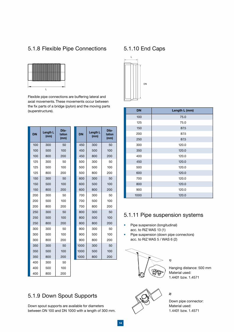
5.1.8 Flexible Pipe Connections
Flexible pipe connections are buffering lateral and axial movements. These movements occur between the fix parts of a bridge (pylon) and the moving parts (superstructure).
DN Length L (mm)
Dila-tation (mm)
100 300 50
100 500 100
100 800 200
125 300 50
125 500 100
125 800 200
150 300 50
150 500 100
150 800 200
200 300 50
200 500 100
200 800 200
250 300 50
250 500 100
250 800 200
300 300 50
300 500 100
300 800 200
350 300 50
350 500 100
350 800 200
400 300 50
400 500 100
400 800 200
DN Length L (mm)
Dila-tation (mm)
450 300 50
450 500 100
450 800 200
500 300 50
500 500 100
500 800 200
600 300 50
600 500 100
600 800 200
700 300 50
700 500 100
700 800 200
800 300 50
800 500 100
800 800 200
900 300 50
900 500 100
900 800 200
1000 300 50
1000 500 100
1000 800 200
L
5.1.10 End Caps
DN Length L (mm)
100 75.0
125 75.0
150 87.5
200 87.5
250 87.5
300 120.0
350 120.0
400 120.0
450 120.0
500 120.0
600 120.0
700 120.0
800 120.0
900 120.0
1000 120.0
5.1.11 Pipe suspension systems
• Pipe suspension (longitudinal) acc. to RIZ WAS 13 (1)• Pipe suspension (down pipe connectors) acc. to RIZ WAS 5 / WAS 6 (2)
Hanging distance: 500 mmMaterial used: 1.4401 bzw. 1.4571
Down pipe connector:Material used:1.4401 bzw. 1.4571
1)
2)
15
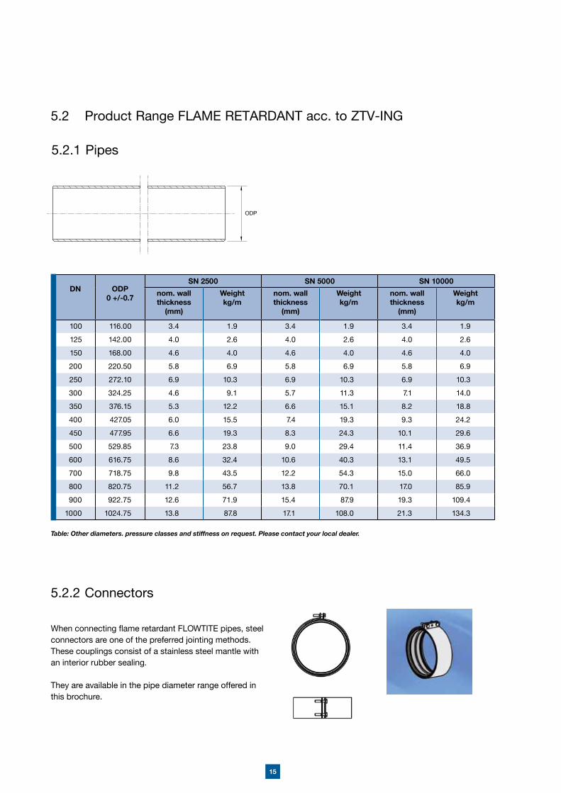
5.2 Product Range FLAME RETARDANT acc. to ZTV-ING
When connecting flame retardant FLOWTITE pipes, steel connectors are one of the preferred jointing methods. These couplings consist of a stainless steel mantle with an interior rubber sealing.
They are available in the pipe diameter range offered in this brochure.
5.2.2 Connectors
5.2.1 Pipes
ODP
Table: Other diameters. pressure classes and stiffness on request. Please contact your local dealer.
DN ODP0 +/-0.7
SN 2500 SN 5000 SN 10000
nom. wall thickness
(mm)
Weightkg/m
nom. wall thickness
(mm)
Weightkg/m
nom. wall thickness
(mm)
Weightkg/m
100 116.00 3.4 1.9 3.4 1.9 3.4 1.9
125 142.00 4.0 2.6 4.0 2.6 4.0 2.6
150 168.00 4.6 4.0 4.6 4.0 4.6 4.0
200 220.50 5.8 6.9 5.8 6.9 5.8 6.9
250 272.10 6.9 10.3 6.9 10.3 6.9 10.3
300 324.25 4.6 9.1 5.7 11.3 7.1 14.0
350 376.15 5.3 12.2 6.6 15.1 8.2 18.8
400 427.05 6.0 15.5 7.4 19.3 9.3 24.2
450 477.95 6.6 19.3 8.3 24.3 10.1 29.6
500 529.85 7.3 23.8 9.0 29.4 11.4 36.9
600 616.75 8.6 32.4 10.6 40.3 13.1 49.5
700 718.75 9.8 43.5 12.2 54.3 15.0 66.0
800 820.75 11.2 56.7 13.8 70.1 17.0 85.9
900 922.75 12.6 71.9 15.4 87.9 19.3 109.4
1000 1024.75 13.8 87.8 17.1 108.0 21.3 134.3
16
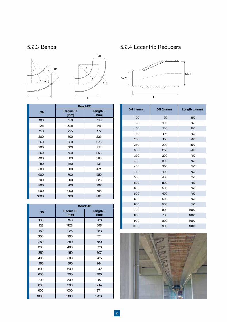
5.2.3 Bends
Bend 45�
DN Radius R (mm)
Length L (mm)
100 150 118
125 187.5 147
150 225 177
200 300 236
250 350 275
300 400 314
350 450 353
400 500 393
450 550 431
500 600 471
600 700 550
700 800 628
800 900 707
900 1000 785
1000 1100 864
Bend 90�
DN Radius R (mm)
Length L (mm)
100 150 236
125 187.5 295
150 225 353
200 300 471
250 350 550
300 400 628
350 450 707
400 500 785
450 550 864
500 600 942
600 700 1100
700 800 1257
800 900 1414
900 1000 1571
1000 1100 1728
5.2.4 Eccentric Reducers
L
DN 1
DN 2
L L
DN 1 (mm) DN 2 (mm) Length L (mm)
100 50 250
125 100 250
150 100 250
150 125 250
200 150 500
250 200 500
300 250 500
350 300 750
400 300 750
400 350 750
450 400 750
500 400 750
600 500 750
600 500 750
500 400 750
600 500 750
600 500 750
700 600 1000
800 700 1000
900 800 1000
1000 900 1000
17
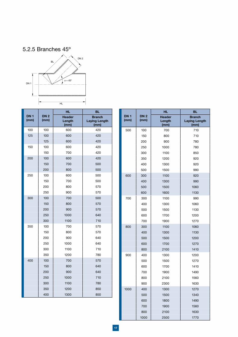
5.2.5 Branches 45�
DN 1 (mm)
DN 2 (mm)
HL BL
Header Length(mm)
BranchLaying Length
(mm)
100 100 600 420
125 100 600 420
125 600 420
150 100 600 420
150 700 420
200 100 600 420
150 700 500
200 800 500
250 100 600 500
150 700 500
200 800 570
250 900 570
300 100 700 500
150 800 570
200 900 570
250 1000 640
300 1100 710
350 100 700 570
150 800 570
200 900 640
250 1000 640
300 1100 710
350 1200 780
400 100 700 570
150 800 640
200 900 640
250 1000 710
300 1100 780
350 1200 850
400 1300 850
DN 1 (mm)
DN 2 (mm)
HL BL
Header Length(mm)
BranchLaying Length
(mm)
500 100 700 710
150 800 710
200 900 780
250 1000 780
300 1100 850
350 1200 920
400 1300 920
500 1500 990
600 300 1100 920
400 1300 990
500 1500 1060
600 1600 1130
700 300 1100 990
400 1300 1060
500 1500 1130
600 1700 1200
700 1900 1270
800 300 1100 1060
400 1300 1130
500 1500 1200
600 1700 1270
800 2100 1410
900 400 1300 1200
500 1500 1270
600 1700 1410
700 1900 1490
800 2100 1560
900 2300 1630
1000 400 1300 1270
500 1500 1340
600 1800 1490
700 1900 1560
800 2100 1630
1000 2500 1770
HL
BL
DN 1
DN 2
18
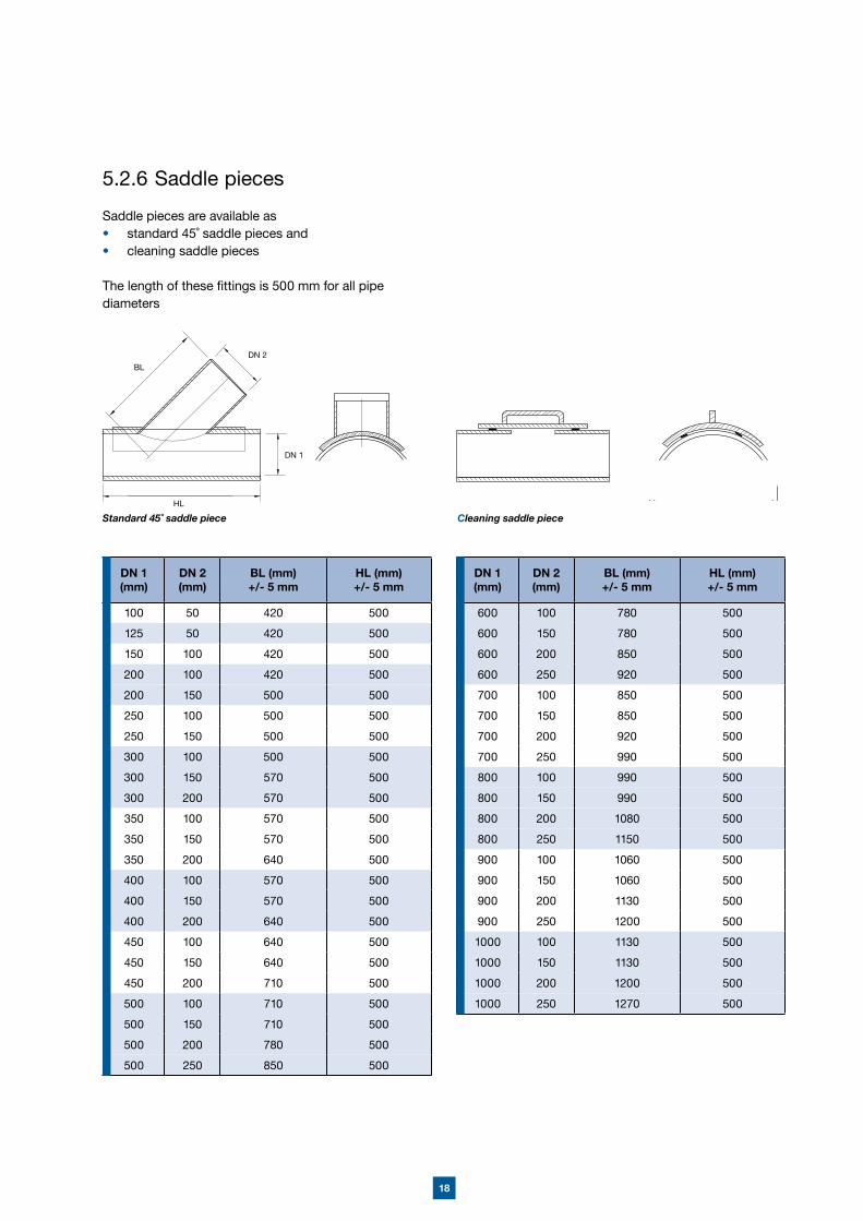
5.2.6 Saddle pieces
Saddle pieces are available as• standard 45˚ saddle pieces and • cleaning saddle pieces
The length of these fittings is 500 mm for all pipe diameters
Standard 45˚ saddle piece HL
DN 1
DN 2
Cleaning saddle piece
BL
DN 1 (mm)
DN 2 (mm)
BL (mm)+/- 5 mm
HL (mm)+/- 5 mm
600 100 780 500
600 150 780 500
600 200 850 500
600 250 920 500
700 100 850 500
700 150 850 500
700 200 920 500
700 250 990 500
800 100 990 500
800 150 990 500
800 200 1080 500
800 250 1150 500
900 100 1060 500
900 150 1060 500
900 200 1130 500
900 250 1200 500
1000 100 1130 500
1000 150 1130 500
1000 200 1200 500
1000 250 1270 500
DN 1 (mm)
DN 2 (mm)
BL (mm)+/- 5 mm
HL (mm)+/- 5 mm
100 50 420 500
125 50 420 500
150 100 420 500
200 100 420 500
200 150 500 500
250 100 500 500
250 150 500 500
300 100 500 500
300 150 570 500
300 200 570 500
350 100 570 500
350 150 570 500
350 200 640 500
400 100 570 500
400 150 570 500
400 200 640 500
450 100 640 500
450 150 640 500
450 200 710 500
500 100 710 500
500 150 710 500
500 200 780 500
500 250 850 500
19
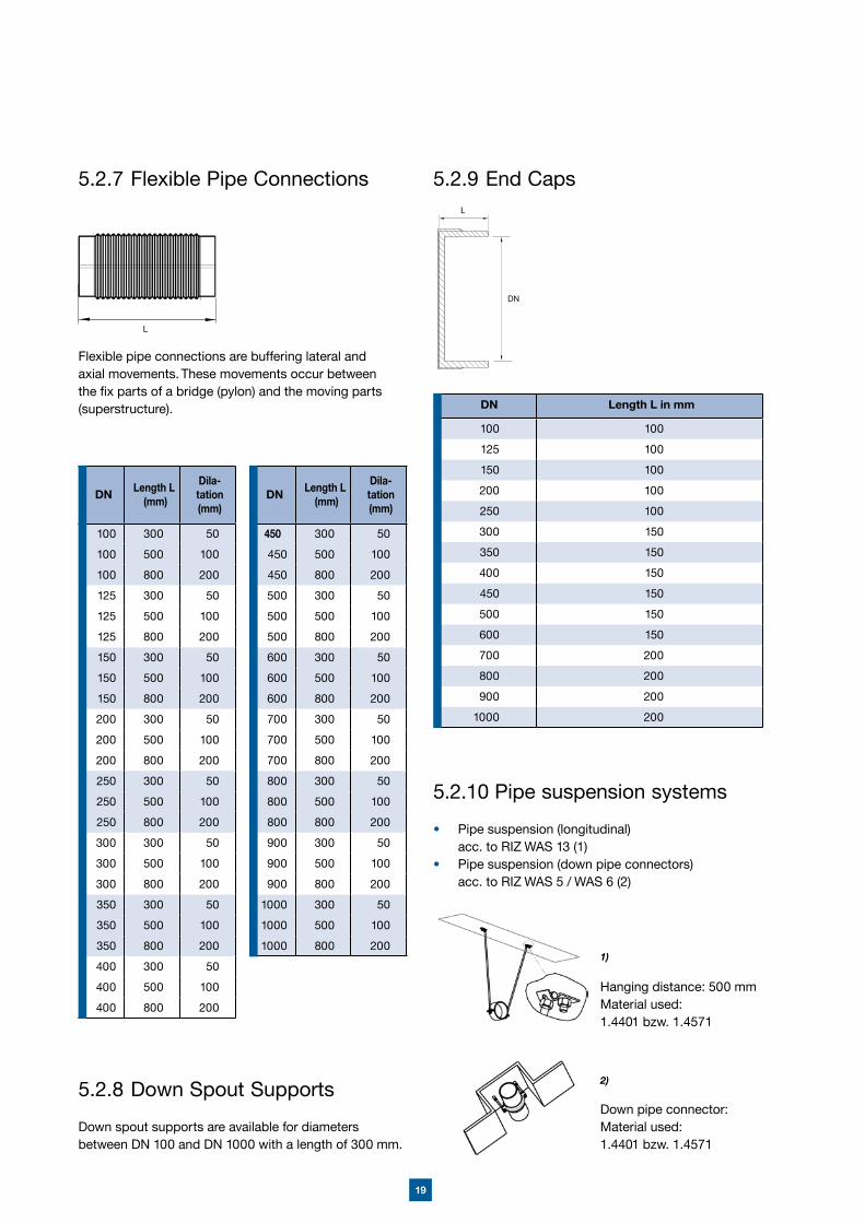
5.2.8 Down Spout Supports
Down spout supports are available for diameters between DN 100 and DN 1000 with a length of 300 mm.
5.2.7 Flexible Pipe Connections
Flexible pipe connections are buffering lateral and axial movements. These movements occur between the fix parts of a bridge (pylon) and the moving parts (superstructure).
DN Length L (mm)
Dila-tation (mm)
100 300 50
100 500 100
100 800 200
125 300 50
125 500 100
125 800 200
150 300 50
150 500 100
150 800 200
200 300 50
200 500 100
200 800 200
250 300 50
250 500 100
250 800 200
300 300 50
300 500 100
300 800 200
350 300 50
350 500 100
350 800 200
400 300 50
400 500 100
400 800 200
DN Length L (mm)
Dila-tation (mm)
450 300 50
450 500 100
450 800 200
500 300 50
500 500 100
500 800 200
600 300 50
600 500 100
600 800 200
700 300 50
700 500 100
700 800 200
800 300 50
800 500 100
800 800 200
900 300 50
900 500 100
900 800 200
1000 300 50
1000 500 100
1000 800 200
L
5.2.9 End Caps
DN Length L in mm
100 100
125 100
150 100
200 100
250 100
300 150
350 150
400 150
450 150
500 150
600 150
700 200
800 200
900 200
1000 200
DN
5.2.10 Pipe suspension systems
• Pipe suspension (longitudinal) acc. to RIZ WAS 13 (1)• Pipe suspension (down pipe connectors) acc. to RIZ WAS 5 / WAS 6 (2)
Hanging distance: 500 mmMaterial used: 1.4401 bzw. 1.4571
Down pipe connector:Material used: 1.4401 bzw. 1.4571
1)
2)
20
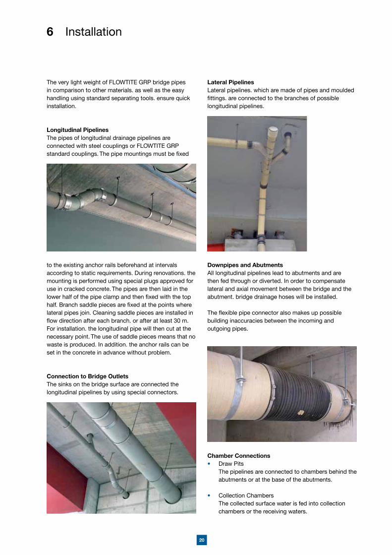
The very light weight of FLOWTITE GRP bridge pipes in comparison to other materials. as well as the easy handling using standard separating tools. ensure quick installation.
Longitudinal PipelinesThe pipes of longitudinal drainage pipelines are connected with steel couplings or FLOWTITE GRP standard couplings. The pipe mountings must be fixed
to the existing anchor rails beforehand at intervals according to static requirements. During renovations. the mounting is performed using special plugs approved for use in cracked concrete. The pipes are then laid in the lower half of the pipe clamp and then fixed with the top half. Branch saddle pieces are fixed at the points where lateral pipes join. Cleaning saddle pieces are installed in flow direction after each branch. or after at least 30 m. For installation. the longitudinal pipe will then cut at the necessary point. The use of saddle pieces means that no waste is produced. In addition. the anchor rails can be set in the concrete in advance without problem.
Connection to Bridge OutletsThe sinks on the bridge surface are connected the longitudinal pipelines by using special connectors.
6 Installation
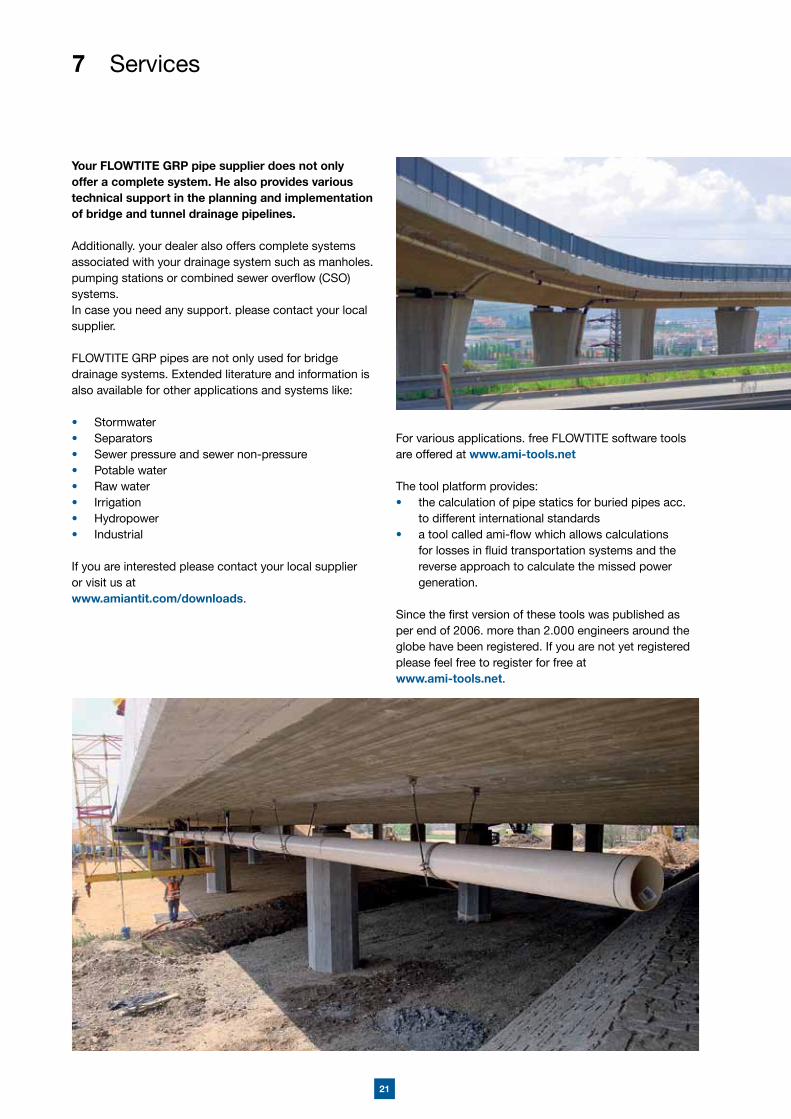
Lateral PipelinesLateral pipelines. which are made of pipes and moulded fittings. are connected to the branches of possible longitudinal pipelines.
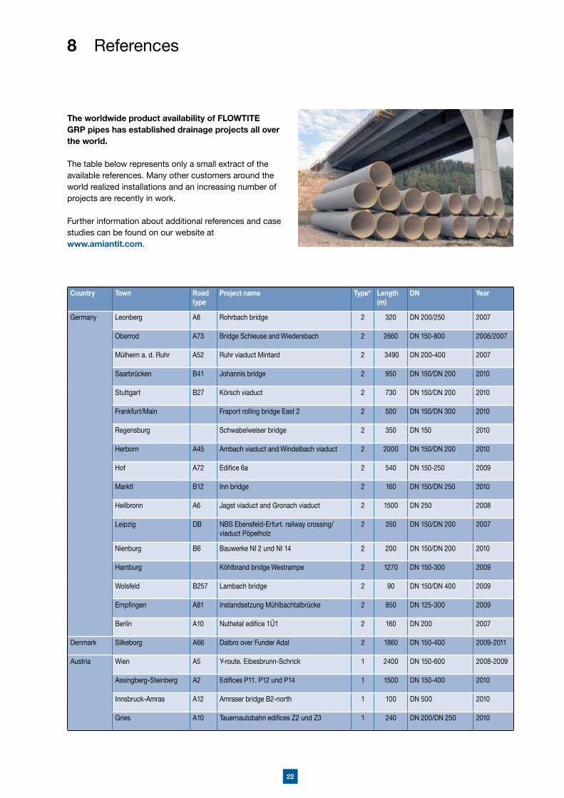
Downpipes and AbutmentsAll longitudinal pipelines lead to abutments and are then fed through or diverted. In order to compensate lateral and axial movement between the bridge and the abutment. bridge drainage hoses will be installed.
The flexible pipe connector also makes up possible building inaccuracies between the incoming and outgoing pipes.
Chamber Connections• Draw Pits The pipelines are connected to chambers behind the
abutments or at the base of the abutments.
• Collection Chambers The collected surface water is fed into collection
chambers or the receiving waters.
21
7 Services
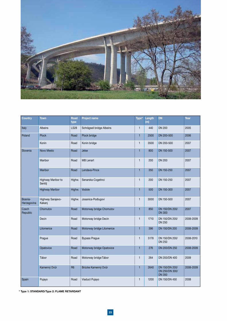
Your FLOWTITE GRP pipe supplier does not only offer a complete system. He also provides various technical support in the planning and implementation of bridge and tunnel drainage pipelines.
Additionally. your dealer also offers complete systems associated with your drainage system such as manholes. pumping stations or combined sewer overflow (CSO) systems.In case you need any support. please contact your local supplier.
FLOWTITE GRP pipes are not only used for bridge drainage systems. Extended literature and information is also available for other applications and systems like:
• Stormwater• Separators• Sewer pressure and sewer non-pressure• Potable water• Raw water• Irrigation• Hydropower• Industrial
If you are interested please contact your local supplier or visit us at www.amiantit.com/downloads.
For various applications. free FLOWTITE software tools are offered at www.ami-tools.net
The tool platform provides:• the calculation of pipe statics for buried pipes acc.
to different international standards • a tool called ami-flow which allows calculations
for losses in fluid transportation systems and the reverse approach to calculate the missed power generation.
Since the first version of these tools was published as per end of 2006. more than 2.000 engineers around the globe have been registered. If you are not yet registered please feel free to register for free at www.ami-tools.net.
22
8 References
The worldwide product availability of FLOWTITE GRP pipes has established drainage projects all over the world.
The table below represents only a small extract of the available references. Many other customers around the world realized installations and an increasing number of projects are recently in work.
Further information about additional references and case studies can be found on our website atwww.amiantit.com.
Country Town Roadtype
Project name Type* Length(m)
DN Year
Germany Leonberg A8 Rohrbach bridge 2 320 DN 200/250 2007
Oberrod A73 Bridge Schleuse and Wiedersbach 2 2660 DN 150-800 2006/2007
Mülheim a. d. Ruhr A52 Ruhr viaduct Mintard 2 3490 DN 200-400 2007
Saarbrücken B41 Johannis bridge 2 950 DN 150/DN 200 2010
Stuttgart B27 Körsch viaduct 2 730 DN 150/DN 200 2010
Frankfurt/Main Fraport rolling bridge East 2 2 500 DN 150/DN 300 2010
Regensburg Schwabelweiser bridge 2 350 DN 150 2010
Herborn A45 Ambach viaduct and Windelbach viaduct 2 2000 DN 150/DN 200 2010
Hof A72 Edifice 6a 2 540 DN 150-250 2009
Marktl B12 Inn bridge 2 160 DN 150/DN 250 2010
Heilbronn A6 Jagst viaduct and Gronach viaduct 2 1500 DN 250 2008
Leipzig DB NBS Ebensfeld-Erfurt. railway crossing/viaduct Pöpelholz
2 350 DN 150/DN 200 2007
Nienburg B6 Bauwerke NI 2 und NI 14 2 200 DN 150/DN 200 2010
Hamburg Köhlbrand bridge Westrampe 2 1270 DN 150-300 2009
Wolsfeld B257 Lambach bridge 2 90 DN 150/DN 400 2009
Empfingen A81 Instandsetzung Mühlbachtalbrücke 2 850 DN 125-300 2009
Berlin A10 Nuthetal edifice 1Ü1 2 160 DN 200 2007
Denmark Silkeborg A66 Dalbro over Funder Adal 2 1860 DN 150-400 2009-2011
Austria Wien A5 Y-route. Eibesbrunn-Schrick 1 2400 DN 150-600 2008-2009
Assingberg-Steinberg A2 Edifices P11. P12 und P14 1 1500 DN 150-400 2010
Innsbruck-Amras A12 Amraser bridge B2-north 1 100 DN 500 2010
Gries A10 Tauernautobahn edifices Z2 und Z3 1 240 DN 200/DN 250 2010
23
* Type 1: STANDARD/Type 2: FLAME RETARDANT
Country Town Roadtype
Project name Type* Length(m)
DN Year
Italy Albeins LS28 Schrägseil bridge Albeins 1 440 DN 200 2005
Poland Plock Road Plock bridge 1 2500 DN 200-500 2006
Konin Road Konin bridge 1 3500 DN 200-500 2007
Slovenia Novo Mesto Road Jelse 1 800 DN 150-500 2007
Maribor Road MB Lenart 1 200 DN 200 2007
Maribor Road Lendava-Pince 1 350 DN 150-250 2007
Highway Maribor to Sentilj
Highw. Senarska-Cogetinci 1 200 DN 150-250 2007
Highway Maribor Highw. Vodole 1 500 DN 150-300 2007
Bosnia-Herzegovina
Highway Sarajevo- Kakanj
Highw. Josanica-Podlugovi 1 3000 DN 150-500 2007
Czech Republic
Chomutov Road Motorway bridge Chomutov 1 850 DN 150/DN 200/DN 300
2007
Decin Road Motorway bridge Decin 1 1710 DN 150/DN 200/DN 250
2008-2009
Litomerice Road Motorway bridge Litomerice 1 396 DN 150/DN 200 2008-2009
Prague Road Bypass Prague 1 5178 DN 150/DN 200/DN 250
2008-2010
Opatovice Road Motorway bridge Opatovice 1 276 DN 200/DN 250 2008-2009
Tábor Road Motorway bridge Tábor 1 264 DN 200/DN 400 2009
Kamenný Dvůr R6 Brücke Kamenný Dvůr 1 2640 DN 150/DN 200/DN 250/DN 300/DN 350
2008-2009
Spain Pujayo Road Viaduct Pujayo 1 1200 DN 150/DN 450 2008

This handbook is intended as a guide only. All values listed in the product specifications are nominal. Unsatisfactory product results may occur due to environmental fluctuations. variations in operating procedures. or interpolation of data. We highly recommend that any personnel using this data have specialised training and experience in the application of these products and their normal installation and operating conditions.
The engineering staff should always be consulted before any of these products are installed to ensure the suitability of the products for their intended purpose and applications. We hereby state that we do not accept any liability. and will not be held liable. for any losses or damage which may result from the installation or use of any products listed in this handbook as we have not determined the degree of care required for product installation or service. We reserve the right to revise this data. as necessary. without notice.
We welcome comments regarding this handbook.
BR
ÜC
KE
NR
OH
RE
-V1
08-1
0-E
Saudi Arabian Amiantit Company- European Headquarters -Am Seestern 1840547 DüsseldorfGermanyTel.: +49 211 550 270 0Fax: +49 211 550 270 [email protected]
AMITECH Germany GmbH Am Fuchsloch 19 04720 Mochau. OT Großsteinbach GermanyTel.: + 49 34 31 71 82 0 Fax: + 49 34 31 70 23 24 [email protected] www.iH-germany.dewww.amiantit.comDistributed by: