Embed Size (px)
Citation preview
INTERNATIONAL JOURNAL of ENGINEERING TECHNOLOGIES Sahin and Bayraktar, Vol.1, No.3, 2015
106
Flow Visualization of Sloshing in an Accelerated
Two-Dimensional Rectangular Tank
Gurhan Sahin, Seyfettin Bayraktar‡
Department of Naval Architecture & Marine Engineering, Faculty of Naval Architecture & Maritime,
Yildiz Technical University, 34349 Istanbul, Turkey
([email protected], [email protected])
‡ Corresponding Author; Seyfettin Bayraktar, Yildiz Technical University, Department of Naval Architecture & Marine
Engineering, Faculty of Naval Architecture & Maritime, 34349 Istanbul, Turkey, Tel: +90 212 383 7070,
Received: 31.07.2015 Accepted:11.09.2015
Abstract-In the present paper, sloshing in a Two-Dimensional (2D) square liquid tank subjected to horizontal excitation is
investigated by means of Computational Fluid Dynamics (CFD) technique. The tank with/out the vertical and horizontal
baffles located at each side walls of the tank is moved on positive (+) x-axis for the excitation of 4.5 m2/s for each case study.
After series of simulations results obtained for each tank configuration are compared and flow is visualized for the tanks that
are 50% filled with the fresh water.
Keywords: Computational fluid dynamics (CFD), turbulence, sloshing, fluid, accelerated tank
1. Introduction
Sloshing is an important engineering problem. It may
cause large deformations to wall and supporting structures in
partially filled tanks. According to the classification
societies` guidance sloshing may be defined as violent
behavior of the liquid contents in tanks [1]. The phenomenon
can be seen in many industries including automotive,
aerospace, motorcycle, shipbuilding and maritime from the
sloshing oscillations in aircrafts or space-crafts to storage
tanks of ocean-going ships [2, 3].
Different wave conditions in partially filled tanks,
uncontrolled loading/unloading processes, structural
frequencies, shape and position of the tank, sources of the
motions, filling levels inside the tanks, density of the fluid,
etc. may cause sloshing. The tanks may be rectangular,
prismatic, tapered, spherical and cylindrical. The carried
liquids may be oil, liquefied gas, water, molasses and caustic
soda [4]. All these above parameters show how the sloshing
is complex and difficult to analyze. As stated by Rudman and
Cleary [5] sloshing affects ship stability and therefore, great
attention must be paid during not also loading and/or
unloading period but also transportation. Due to demand of
sloshing analysis for building large Liquefied Natural Gases
(LNG) carriers and LNG platforms classification societies
publish rules and guidance on this issue. For example,
Bureau Veritas [1] and Det Norske Veritas [6] show the
importance and specify the basic requirements for approval
of LNG carriers and floating structures as well as provide
necessary methodology to assess the sloshing loads and how
to use these methodologies. One may ask why tanks are left
partially-filled. The reason is that partial fillings in LNG
carriers are a consequence of boil-off of gas during
operations [4]. Up to now many experimental and numerical
works have been performed. Krata [7] presented the results
of an experimental and numerical works of a tank filled
partially with the water. The pressure was measured while
the tank was oscillated with the amplitude of 18, 30, and
40 which reflects the worst heavy sea conditions. Results
showed that the measured pressure consists of non-impulsive
dynamic pressure and impulsive (impact) pressure. The first
one varies slowly due to the global movement of the liquid in
the tank while the second lasts shortly and due to the
hydraulic jump. An improved volume of fluid (VOF) model
was developed by Wemmenhove et al. [8] and the numerical
results were compared by a 1:10 model test. Although no any
details on computational approach were given it was claimed
that both numerical and experimental results were in a good
agreement. Hou et al. [9] imposed external single and
multiple excitations to the tank and analyzed the sloshing by
CFD technique. It was revealed that the sloshing effects
INTERNATIONAL JOURNAL of ENGINEERING TECHNOLOGIES Sahin and Bayraktar, Vol.1, No.3, 2015
107
increased when the numbers of coupled excitations were
added. Shoji and Munakata [10] tried to analyze the sloshing
due to an earthquake by means of Fluid-Structure Interaction
(FSI) and their results cleared that the current potential
theories does not agree so much with the FSI analyses. Lots
of methods have been employed to analyze the sloshing
characteristics such as quasi-static method, hydrodynamics
method, experimental method, equivalent mechanical
method and computer simulation. Interested readers may find
detailed knowledge in the work of Xue-Lian et al. [11]. Each
technique has some advantages and disadvantages and
among them experimental and computational techniques take
more interests.
One of the fuel tank design objectives is to effectively
reduce noise level caused by fluid motion inside the tank by
designing baffles and separators to control the sloshing. In
addition, alternate materials and manufacturing processes are
evaluated for fuel tank design in order to reduce weight and
cost and to provide structural integrity for higher structural
performance. Sloshing in the tank may be controlled by
incorporating baffles, and the effectiveness highly depends
on the shape, the location, and the number of baffles inside a
tank.
In the present paper, one of the test cases of Akyildiz and
Celebi [12] and Javanshir et al. [13] is inspired where a
rectangular tank was separated into mainly three regions by
means of a vertical and two horizontal baffles. In addition to
these types of configurations, a new one is introduced in the
present paper and analyzed by means of CFD. The horizontal
baffles that connected to the left and rights walls of the tanks
are raised 15 upwards.
2. Figures and Tables
It is obvious that sloshing occurs due to motion of fluid
inside partially filled moving tank. As a passive control
method baffles can be used to reduce the severe effects of
sloshing. The following case studies simulate sloshing in a
partially filled rigid tanks with and without the baffles and
report the results for each configurations.
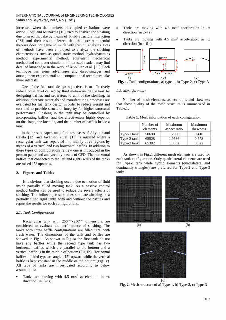
2.1. Tank Configurations
Rectangular tank with 250mm
x250mm
dimensions are
considered to evaluate the performance of sloshing. The
tanks with three baffle configurations are filled 50% with
fresh water. The dimensions of the tank and baffles are
showed in Fig.1. As shown in Fig.1a the first tank do not
have any baffles while the second type tank has two
horizontal baffles which are parallel to the bottom and a
vertical baffle is in the middle of bottom (Fig.1b). Horizontal
baffles of third type are angled 15 upward while the vertical
baffle is kept constant in the middle of the bottom (Fig.1c).
All type of tanks are investigated according to below
assumptions:
Tanks are moving with 4.5 m/s2 acceleration in +x
direction (in 0-2 s)
Tanks are moving with 4.5 m/s2 acceleration in -x
direction (in 2-4 s)
Tanks are moving with 4.5 m/s2 acceleration in +x
direction (in 4-6 s)
(a) (b) (c)
Fig. 1. Tank configurations, a) type-1, b) Type-2, c) Type-3
2.2. Mesh Structure
Number of mesh elements, aspect ratios and skewness
that show quality of the mesh structure is summarized in
Table.1.
Table 1. Mesh information of each configuration
Number of
elements
Maximum
aspect ratio
Maximum
skewness
Type-1 tank 50690 1.2896 0.410
Type-2 tank 65528 1.9586 0.573
Type-3 tank 65302 1.8882 0.622
As shown in Fig.2, different mesh elements are used for
each tank configuration. Only quadrilateral elements are used
for Type-1 tank while hybrid elements (quadrilateral and
dominantly triangles) are preferred for Type-2 and Type-3
tanks.
(a) (b)
(c)
Fig. 2. Mesh structure of a) Type-1, b) Type-2, c) Type-3
INTERNATIONAL JOURNAL of ENGINEERING TECHNOLOGIES Sahin and Bayraktar, Vol.1, No.3, 2015
108
3. Mathematical Model
The equations used to simulate the sloshing are the
continuity (Eq.1), Navier-Stokes (Eq.2) and VOF equations.
These are given in general form as follows:
0V
(1)
BFVpDt
VD
1 (2)
The momentum equation is dependent on the volume
fractions of all phases and given in Eq.3
VB FFVpVVt
u
1 (3)
where V
is the fluid velocity relative to tank, p is pressure; ρ
is fluid density and µ is viscosity. FB and Fv state body force
and virtual body force induced by the motion of tank.
As stated in detail by Nema [14] there are several techniques
such as
Moving grid or Lagrangian approach (capturing),
Fixed grid or Eulerian approach (tracking),
Combined method of Langrangian and Eulerian
for tracking immiscible interfaces. In the present study VOF,
a part of Eulerian approach, has been used. The VOF model
assumes that there is no any interaction between all the fluid
phases (air and water here). For each control volume, the
volume fraction of the phase in the cell will be introduced
and the volume fraction of all the phases sums to unity. If b
represent the both fluid`s volume fraction in the cell, then the
following three conditions are possible:
b=0: Shows the cell is empty (no fluid of b type is
present)
b=1: Shows the cell is full (only b type fluid is present)
10 b : Shows the cell contain the interface between the
both fluid and one or more other type of fluid.
Equation of volume fraction (VOF) for the both phase is
given in Eq.4.
baabbbbbb mmsV
t b
1 (4)
where abm , bam and abs is the mass transfer from a to b
phase, mass transfer from b to a phase and source term which
permits the use of cavitation model. For n phases:
n
b
b
1
1 (5)
Following equation is used to calculate physical parameters
in the 2-phase flow for a and b:
ab
ab
1
1 (6)
Where is defined as 1 for water and 0 for air.
As turbulence model, standard k- is selected that requires
the solution of k, turbulent kinetic energy (Eq.7) and , its
dissipation rate (Eq.8).
k
jk
t
jj
jp
x
k
xx
ku
t
k (7)
k
Ck
PCxxx
u
tK
j
t
jj
j2
21
(8)
where PK is the production of kinetic energy. Value of each
coefficient seen in the equations are given in Table 2.
Table 2. Value of coefficients.
1C 2C C k
1.44 1.92 0.09 1.0 1.3
It is assumed that there is no slip on tank sides, bottom
and top walls. The related equations are solved for time step
of 0.01 second for all cases. Recommendations of Javanshir
et al. [13] are followed initially. The model was validated by
theory [15] and then baffles that are parallels and angled to
the bottom of the thanks are used to reduce liquid sloshing.
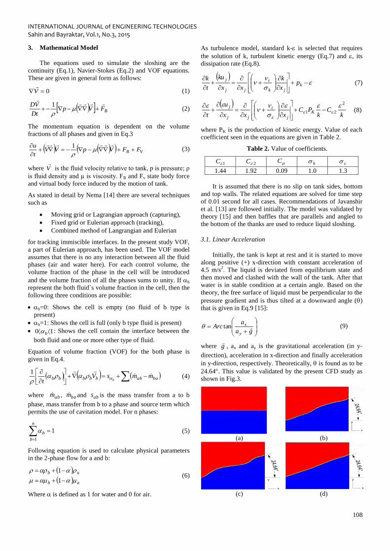
3.1. Linear Acceleration
Initially, the tank is kept at rest and it is started to move
along positive (+) x-direction with constant acceleration of
4.5 m/s2. The liquid is deviated from equilibrium state and
then moved and clashed with the wall of the tank. After that
water is in stable condition at a certain angle. Based on the
theory, the free surface of liquid must be perpendicular to the
pressure gradient and is thus tilted at a downward angle ()
that is given in Eq.9 [15]:
ga
aArc
y
x tan (9)
where g
, ax and ay is the gravitational acceleration (in y-
direction), acceleration in x-direction and finally acceleration
in y-direction, respectively. Theoretically, is found as to be
24.64. This value is validated by the present CFD study as
shown in Fig.3.
(a) (b)
(c) (d)
INTERNATIONAL JOURNAL of ENGINEERING TECHNOLOGIES Sahin and Bayraktar, Vol.1, No.3, 2015
109
Fig. 3. Sloshing in a rectangular tank without barrels under
linear acceleration of 4.5 m/s2 in the (+) x-direction during a)
t=0, b) t=2 seconds, c) t=5.5 seconds, d) t=10 seconds
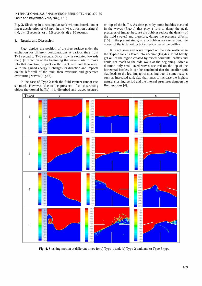
4. Results and Discussion
Fig.4 depicts the position of the free surface under the
excitation for different configurations at various time from
T=1 second to T=6 seconds. Since flow is excitated towards
the (+)x direction at the beginning the water starts to move
into that direction, impact on the right wall and then rises.
With the gained energy it changes its direction and impacts
on the left wall of the tank, then overturns and generates
overturning waves (Fig.4a).
In the case of Type-2 tank the fluid (water) cannot rise
so much. However, due to the presence of an obstructing
object (horizontal baffle) it is disturbed and waves occured
on top of the baffle. As time goes by some bubbles occured
in the waves (Fig.4b) that play a role to damp the peak
pressures of impact because the bubbles reduce the density of
the fluid (water) and therefore, damps the pressure effects,
[16]. In the present study, no any bubbles are seen around the
corner of the tank ceiling but at the corner of the baffles.
It is not seen any wave impact on the side walls when
the Type-3 tank is taken into account (Fig.4c). Fluid barely
get out of the region created by raised horizontal baffles and
could not reach to the side walls at the beginning. After a
duration only small-sized waves occured on the top of the
horizontal baffles. It can be concluded that the smaller tank
size leads to the less impact of sloshing due to some reasons
such as increased tank size that tends to increase the highest
natural sloshing period and the internal structures dampen the
fluid motions [4].
T (sec) a b c
1
2
4
6
Fig. 4. Sloshing motion at different times for a) Type-1 tank, b) Type-2 tank and c) Type-3 type
INTERNATIONAL JOURNAL of ENGINEERING TECHNOLOGIES Sahin and Bayraktar, Vol.1, No.3, 2015
110
At the beginning, type-1 tank seems the worst while
Type-2 is the best because the movement of the water
towards the left and right side walls can be prevented.
Type-3 is better than Type-1, however, worse than Type-2.
On the other hand, when time goes by Type-3 tank
prevents the sloshing and reduces its effects on side walls.
In addition to this, Type-2 prevents violent and
overturning and breaking waves that reduce the effects of
impact of water on the walls. Since the goal of the sloshing
is to study the sloshing pattern and improve the tank
design to reduce noise levels, stresses on the structure and
optimize the baffle arrangements it can be concluded that
Type-3 is the most appropriate among others.
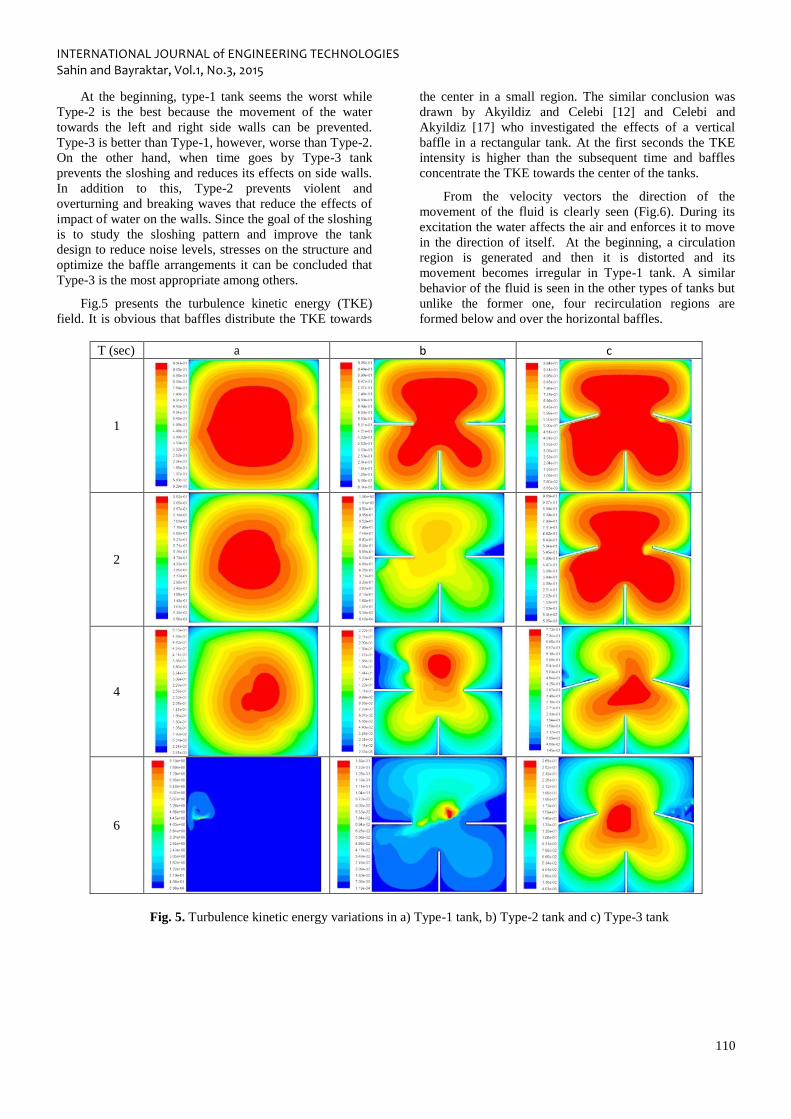
Fig.5 presents the turbulence kinetic energy (TKE)
field. It is obvious that baffles distribute the TKE towards
the center in a small region. The similar conclusion was
drawn by Akyildiz and Celebi [12] and Celebi and
Akyildiz [17] who investigated the effects of a vertical
baffle in a rectangular tank. At the first seconds the TKE
intensity is higher than the subsequent time and baffles
concentrate the TKE towards the center of the tanks.
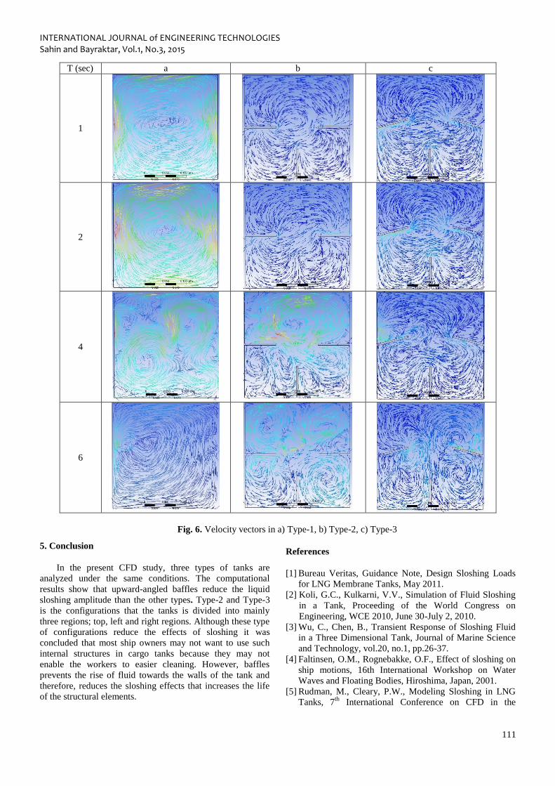
From the velocity vectors the direction of the
movement of the fluid is clearly seen (Fig.6). During its
excitation the water affects the air and enforces it to move
in the direction of itself. At the beginning, a circulation
region is generated and then it is distorted and its
movement becomes irregular in Type-1 tank. A similar
behavior of the fluid is seen in the other types of tanks but
unlike the former one, four recirculation regions are
formed below and over the horizontal baffles.
T (sec) a b c
1
2
4
6
Fig. 5. Turbulence kinetic energy variations in a) Type-1 tank, b) Type-2 tank and c) Type-3 tank
INTERNATIONAL JOURNAL of ENGINEERING TECHNOLOGIES Sahin and Bayraktar, Vol.1, No.3, 2015
111
T (sec) a b c
1
2
4
6
Fig. 6. Velocity vectors in a) Type-1, b) Type-2, c) Type-3
5. Conclusion
In the present CFD study, three types of tanks are
analyzed under the same conditions. The computational
results show that upward-angled baffles reduce the liquid
sloshing amplitude than the other types. Type-2 and Type-3
is the configurations that the tanks is divided into mainly
three regions; top, left and right regions. Although these type
of configurations reduce the effects of sloshing it was
concluded that most ship owners may not want to use such
internal structures in cargo tanks because they may not
enable the workers to easier cleaning. However, baffles
prevents the rise of fluid towards the walls of the tank and
therefore, reduces the sloshing effects that increases the life
of the structural elements.
References
[1] Bureau Veritas, Guidance Note, Design Sloshing Loads
for LNG Membrane Tanks, May 2011.
[2] Koli, G.C., Kulkarni, V.V., Simulation of Fluid Sloshing
in a Tank, Proceeding of the World Congress on
Engineering, WCE 2010, June 30-July 2, 2010.
[3] Wu, C., Chen, B., Transient Response of Sloshing Fluid
in a Three Dimensional Tank, Journal of Marine Science
and Technology, vol.20, no.1, pp.26-37.
[4] Faltinsen, O.M., Rognebakke, O.F., Effect of sloshing on
ship motions, 16th International Workshop on Water
Waves and Floating Bodies, Hiroshima, Japan, 2001.
[5] Rudman, M., Cleary, P.W., Modeling Sloshing in LNG
Tanks, 7th
International Conference on CFD in the
INTERNATIONAL JOURNAL of ENGINEERING TECHNOLOGIES Sahin and Bayraktar, Vol.1, No.3, 2015
112
Minerals and Process Industries, CSIRO, Melbourne,
Australia, 9-11 December 2009.
[6] Det Norske Veritas, Classification Notes on Sloshing
Analysis if LNG Membrane Tanks, No.30.9, August
2014.Krata, P., Model of Interaction of Water and Tank`s
Structure in Sloshing Phenomenon, International Journal
of Marine Navigation and Safety of Sea Transportation,
vol.2, no.4, December 2008.
[7] Krata, P, Model of Interaction of Water and Tank`s
Structure in Sloshing Phenomenon, International Journal
of Marine Navigation and Safety of Sea Transportation,
Vol.2, No.4, 2008.
[8] Wemmenhove, R., Luppes, R., Veldman, A.E.P., Bunnik,
T., Numerical Simulation and Model Experiments of
Sloshing in LNG Tanks, International Conference on
Computational Methods in Marine Engineering,
MARINE 2007, Barcelona, Spain.
[9] Hou, L., Li, F., Wu, C., A Numerical Study of Liquid
Sloshing in a Two-Dimensional Tank under External
Excitations, J. Marine Sci. Appl., 11, 305, 310, 2012.
10] Shoji, Y., Munakata, H., Sloshing of Cylindrical Tank
due to Seismic Acceleration, Abaqus Users Conference,
Newport, Rhode Island, May 2008.
[11] Xue-Lian, Z., Xian-Sheng, L., Yuan-yuan, R.,
Equivalent Mechanical Model for Lateral Liquid
Sloshing in Partially Filled Tank Vehicles,
Mathematical Problems in Engineering, vol.2012,
article ID 162825, 2012.
[12] Akyildiz, H., Celebi, M.S., Numerical Computation of
Hydrodynamic Loads on Walls of a Rigid Tank due to
Large Amplitude Liquid Sloshing, Turkish J. of Eng.
Sci., 26, 429-445, 2002a.
[13] Javanshir, A., Elahi, R., Passandideh-Fard, M.,
Numerical Simulation of Liquid Sloshing with Baffles
in the Fuel Container, the 12th
Iranian Aerospace
Society Conference, Amir Kabir University of
Technology, 2013.
[14] Nema, P.K., Computational Study of Sloshing
Behavior in 3-D Rectangular Tank with and without
Baffle under Seismic Excitation, MSc Thesis,
Department of Mechanical Engineering, National
Institute of Technology, Rourkela, India, 2014.
[15] White, F.M., Fluid Mechanics, 5th
Edition, McGraw-
Hill.
[16] Kim, Y., Experimental and Numerical Analyses of
Sloshing Flows, Journal of Engineering Mathematics,
vol.58, issue 1-4, pp.191-210, 2007.
[17] Celebi, M.S., Akyildiz, H., Nonlinear Modelling of
Liquid Sloshing in a Moving Rectangular Tank, Ocean
Engineering, vol.29, issue 12, pp.1527-1553, 2002b.


![Sloshing motion in excited tanks - context/Earthcontextearth.com/wp-content/uploads/2016/07/JCP04.pdf · Sloshing motion in excited tanks ... [35] modelled inviscid sloshing motion](https://img.pdfslide.us/doc/110x75/5a78985e7f8b9aa2448e4299/sloshing-motion-in-excited-tanks-context-motion-in-excited-tanks-35-modelled.jpg)