Embed Size (px)
Citation preview
FLOW-THROUGHFURNACE HUMIDIFIER
InstallationWarranty
MaintenanceTroubleshooting Guide
2 Installation
READ COMPLETE INSTALLATIONINSTRUCTIONS AND TEMPLATE
BEFORE STARTING
Attention Installer:
• Installation work and electrical wiring must be doneby qual i f ied person(s ) in accordance with a l lappl icable codes and s tandards, inc luding f i re -related construction.
• 120V may cause serious injury from electrical shock.Disconnect e lect r ica l power to furnace beforestarting installation.
• Wear safety glasses, work gloves.
• When dril l ing or cutting into ducting be extremelycareful not to damage air conditioner coils or otherfurnace parts.
• This unit must be installed on ducts at least 10” wide.
• Do not install this unit where extreme temperatureexist (below 45°F-above 145°F).
INSTALLATION TIP. Before starting , fully planout the installation. Check for the locations ofhumidi f ier, bypass col lar and damper, thelength and type of ducting required, the watersupply, the water drain, the electrical wiring .This wil l ensure your installation goes as easilyand quickly as possible.
1. The humidifier body mounted level on the return airduct ( to help even water dis t r ibut ion acrossevaporation pad).
2. The humidifier body and bypass duct are installed ateye level , eas i ly access ib le for ins ta l la t ion androutine maintenance.
3. Distance between centers of humidifier body (onreturn cold air duct) and bypass inlet (on the warmair supply duct ) are no more than 30” (to allow forbest air f low).
4. The bypass damper is fully opened.
5. The bypass inlet opening should be at least 6” aboveany restr ict ions (e.g . the air condit ioning coi ls )inside the duct.
6. The humidifier and bypass collar are at the same level.
7. Take the most direct route to join humidifier andbypass collar.
INSTALLATION
STEP #1: RIGHT HAND DUCTING OR LEFT HAND DUCTING
Depending on your furnace or for convenience of yourins ta l la t ion i t may be necessary to convert thehumidif ier for left hand ducting or r ight handingducting . Follow the steps below to switch the sidewhich bypass duct wil l attached to the unit.
1. Remove the humidifier front cover secured in placewith 10-24 plastic thumb screw at the bottom of thecover .Tilt the about 1/2” away from the body and liftthe cover up to free the hooks at the top of the body.
2. Remove all lose components packaged inside. Witha firm pull, disconnect the water tube from the waternozzle and remove the evaporator pad assembly bysliding it toward the top of the humidifier, and thenlift ing it out.
3. Remove the two #6 screws which hold thehumidifier side in place , l i ft the humidifier side outof the right hand position, turn the part and place iton other side of the body.
4. Use two #6 crews removed to secure the humidifierside in the left hand side.
STEP #2 MOUNTING THE HUMIDIFIER ON THE DUCT
1. Use adhesive tape to affix the template onto the ductin the selected location. Use the level line to templateand level to ensure the humidifier will be level.
2. Dril l the 3 marked 1/8” cabinet mounting holes.
3. Dril l 2 marked 7/32” cabinet position holes.
4. Cut out the area marked on the template for thehumidifier plenum.
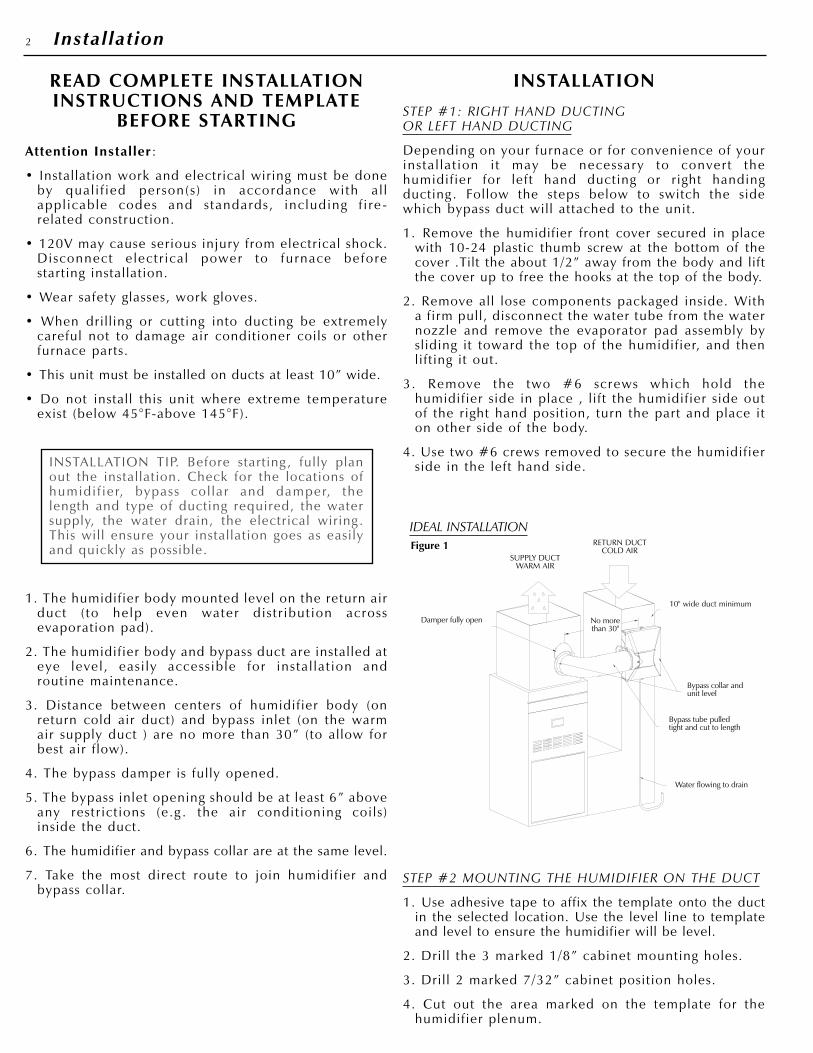
IDEAL INSTALLATION
SUPPLY DUCTWARM AIR
RETURN DUCTCOLD AIR
10" wide duct minimum
Bypass collar andunit level
Bypass tube pulledtight and cut to length
Water flowing to drain
Damper fully open No morethan 30"
Figure 1
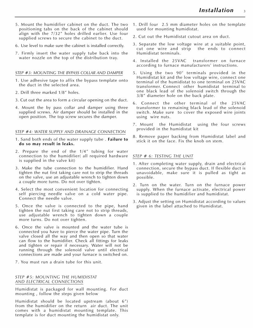
5. Mount the humidifier cabinet on the duct. The twopositioning tabs on the back of the cabinet shouldalign with the 7/32” holes dril led earlier. Use foursupplied screws to secure the cabinet to the duct.
6. Use level to make sure the cabinet is installed correctly.
7. Firmly insert the water supply tube back into thewater nozzle on the top of the distribution tray.
STEP #3: MOUNTING THE BYPASS COLLAR AND DAMPER
1. Use adhesive tape to affix the bypass template ontothe duct in the selected area.
2. Drill three marked 1/8” holes.
3. Cut out the area to form a circular opening on the duct.
4. Mount the by pass collar and damper using threesupplied screws. Air damper should be installed in theopen position. The top screw secures the damper.
STEP #4: WATER SUPPLY AND DRAINAGE CONNECTION
1. Sand both ends of the water supply tube . Failure todo so may result in leaks.
2. Prepare the end of the 1/4” tubing for waterconnection to the humidifier( al l required hardwareis supplied in the valve kit)
3. Make the tube connection to the humidifier. Handtighten the nut first taking care not to strip the threadson the valve, use an adjustable wrench to tighten downa couple more turns. Do not over tighten.
4. Select the most convenient location for connectingself piercing needle valve on a cold water pipe.Connect the needle valve.
5. Once the valve is connected to the pipe, handtighten the nut first taking care not to strip threads,use adjustable wrench to tighten down a couplemore turns. Do not over tighten.
6. Once the valve is mounted and the water tube isconnected you have to pierce the water pipe. Turn thevalve closed all the way and then open so that watercan flow to the humidifier. Check all fittings for leaksand tighten or repair if necessary. Water will not berunning through the solenoid valve until electricalconnections are made and your furnace is switched on.
7. You must run a drain tube for this unit.
STEP #5: MOUNTING THE HUMIDISTATAND ELECTRICAL CONNECTIONS
Humidistat is packaged for wall mounting . For ductmounting , follow the steps given below
Humidistat should be located upstream (about 6”)from the humidifier on the return air duct. The unitcomes with a humidistat mounting template. Thistemplate is for duct mounting the humidistat only.
1. Dril l four 2.5 mm diameter holes on the templateused for mounting humidistat.
2. Cut out the Humidistat cutout area on duct.
3. Separate the low voltage wire at a suitable point,cut one wire and s t r ip the ends to connectHumidistat terminals.
4. Ins ta l led the 25VAC t rans former on furnaceaccording to furnace manufacturers’ instructions.
5. Using the two 90° terminals provided in theHumidistat kit and the low voltage wire, connect oneterminal of the humidistat to one terminal on 25VACtransformer. Connect other humidistat terminal toone black lead of the solenoid switch through the3/8” diameter hole on the back plate.
6. Connect the other terminal of the 25VACtransformer to remaining black lead of the solenoidswitch. Make sure to cover the exposed wire jointsusing wire nuts.
7. Mount the Humidistat using the four screwsprovided in the humidistat kit
8. Remove paper backing from Humidistat label andstick it on the face. Fix the knob on stem.
STEP # 6: TESTING THE UNIT
1. After completing water supply, drain and electricalconnection, secure the bypass duct. If f lexible duct isunavoidable, make sure i t is pul led as t ight aspossible.
2. Turn on the water. Turn on the furnace powersupply. When the furnace activate, electrical poweris supplied to the humidifier and humidistat.
3. Adjust the setting on Humidistat according to valuesgiven in the label attached to Humidistat.
3Installation
WARRANTY
The manufacturer guarantees the for the period of one year from thedate of purchase, the product will be free of defects in workmanshipand/or material. As well the manufacturer offers a life time warranty onthe flow through humidifier body. During the warranty period, we willreplace or repair any defective part at no charge if the product isreturned prepaid to our factory.
This warranty does not cover any labor or shipping costs, or the cost ofreplacement components as part of routine maintenance (such as FlowThrough Humidifier Evaporator Pads, Inlet water Filters, or OrificeFittings). Any damage or failure caused by abuse, misuse, abnormalusage, faulty installation, or improper maintenance will not be coveredby this warranty.
In order to make a claim on this warranty you must be the originalconsumer of the product and you must contact the manufacturer 1-800-465-7300 between 8 AM and 3:30 PM EST Monday to Friday at the firstsign of a defect. You will be required to present to the manufacturer theoriginal bill of sale showing date of purchase, place of purchase, andmodel purchased. Failure to meet these requirements will void yourwarranty.
The manufacturer will not be held responsible for any bodily injuries ordamages to personal property or real estate whether caused directly orindirectly by the product. Some states and provinces do not allow theexclusion or limitation of incidental or consequential damages and somestates or provinces do not allow limitations on how long an impliedwarranty lasts, so these exclusions or limitations may not apply to you.This warranty gives you specific legal rights and you may have otherrights which vary from state to state and province to province.
SAVE THIS DOCUMENT AND ATTACH YOUR RECEIPT.
Date of Purchase Date Of Installation
Place of Purchase Brand and Model#
See attached table regards specific component warranty periods.
MAINTENANCE
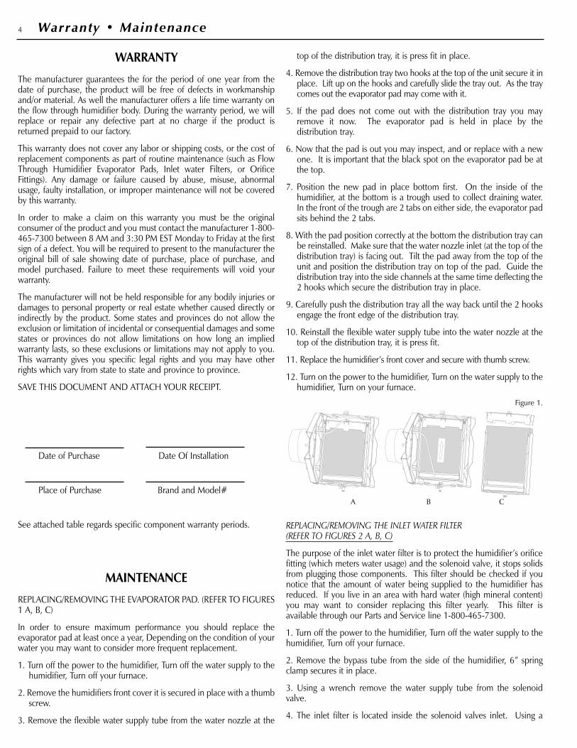
REPLACING/REMOVING THE EVAPORATOR PAD. (REFER TO FIGURES1 A, B, C)
In order to ensure maximum performance you should replace theevaporator pad at least once a year, Depending on the condition of yourwater you may want to consider more frequent replacement.
1. Turn off the power to the humidifier, Turn off the water supply to thehumidifier, Turn off your furnace.
2. Remove the humidifiers front cover it is secured in place with a thumbscrew.
3. Remove the flexible water supply tube from the water nozzle at the
top of the distribution tray, it is press fit in place.
4. Remove the distribution tray two hooks at the top of the unit secure it inplace. Lift up on the hooks and carefully slide the tray out. As the traycomes out the evaporator pad may come with it.
5. If the pad does not come out with the distribution tray you mayremove it now. The evaporator pad is held in place by thedistribution tray.
6. Now that the pad is out you may inspect, and or replace with a newone. It is important that the black spot on the evaporator pad be atthe top.
7. Position the new pad in place bottom first. On the inside of thehumidifier, at the bottom is a trough used to collect draining water.In the front of the trough are 2 tabs on either side, the evaporator padsits behind the 2 tabs.
8. With the pad position correctly at the bottom the distribution tray canbe reinstalled. Make sure that the water nozzle inlet (at the top of thedistribution tray) is facing out. Tilt the pad away from the top of theunit and position the distribution tray on top of the pad. Guide thedistribution tray into the side channels at the same time deflecting the2 hooks which secure the distribution tray in place.
9. Carefully push the distribution tray all the way back until the 2 hooksengage the front edge of the distribution tray.
10. Reinstall the flexible water supply tube into the water nozzle at thetop of the distribution tray, it is press fit.
11. Replace the humidifier’s front cover and secure with thumb screw.
12. Turn on the power to the humidifier, Turn on the water supply to thehumidifier, Turn on your furnace.
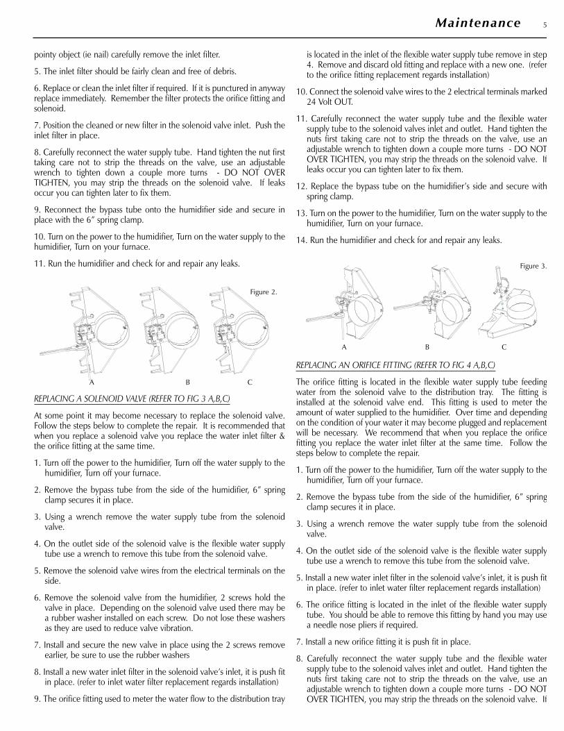
REPLACING/REMOVING THE INLET WATER FILTER(REFER TO FIGURES 2 A, B, C)
The purpose of the inlet water filter is to protect the humidifier’s orificefitting (which meters water usage) and the solenoid valve, it stops solidsfrom plugging those components. This filter should be checked if younotice that the amount of water being supplied to the humidifier hasreduced. If you live in an area with hard water (high mineral content)you may want to consider replacing this filter yearly. This filter isavailable through our Parts and Service line 1-800-465-7300.
1. Turn off the power to the humidifier, Turn off the water supply to thehumidifier, Turn off your furnace.
2. Remove the bypass tube from the side of the humidifier, 6” springclamp secures it in place.
3. Using a wrench remove the water supply tube from the solenoidvalve.
4. The inlet filter is located inside the solenoid valves inlet. Using a
4 Warranty • Maintenance
Figure 1.
A B C
pointy object (ie nail) carefully remove the inlet filter.
5. The inlet filter should be fairly clean and free of debris.
6. Replace or clean the inlet filter if required. If it is punctured in anywayreplace immediately. Remember the filter protects the orifice fitting andsolenoid.
7. Position the cleaned or new filter in the solenoid valve inlet. Push theinlet filter in place.
8. Carefully reconnect the water supply tube. Hand tighten the nut firsttaking care not to strip the threads on the valve, use an adjustablewrench to tighten down a couple more turns - DO NOT OVERTIGHTEN, you may strip the threads on the solenoid valve. If leaksoccur you can tighten later to fix them.
9. Reconnect the bypass tube onto the humidifier side and secure inplace with the 6” spring clamp.
10. Turn on the power to the humidifier, Turn on the water supply to thehumidifier, Turn on your furnace.
11. Run the humidifier and check for and repair any leaks.
REPLACING A SOLENOID VALVE (REFER TO FIG 3 A,B,C)
At some point it may become necessary to replace the solenoid valve.Follow the steps below to complete the repair. It is recommended thatwhen you replace a solenoid valve you replace the water inlet filter &the orifice fitting at the same time.
1. Turn off the power to the humidifier, Turn off the water supply to thehumidifier, Turn off your furnace.
2. Remove the bypass tube from the side of the humidifier, 6” springclamp secures it in place.
3. Using a wrench remove the water supply tube from the solenoidvalve.
4. On the outlet side of the solenoid valve is the flexible water supplytube use a wrench to remove this tube from the solenoid valve.
5. Remove the solenoid valve wires from the electrical terminals on theside.
6. Remove the solenoid valve from the humidifier, 2 screws hold thevalve in place. Depending on the solenoid valve used there may bea rubber washer installed on each screw. Do not lose these washersas they are used to reduce valve vibration.
7. Install and secure the new valve in place using the 2 screws removeearlier, be sure to use the rubber washers
8. Install a new water inlet filter in the solenoid valve’s inlet, it is push fitin place. (refer to inlet water filter replacement regards installation)
9. The orifice fitting used to meter the water flow to the distribution tray
is located in the inlet of the flexible water supply tube remove in step4. Remove and discard old fitting and replace with a new one. (referto the orifice fitting replacement regards installation)
10. Connect the solenoid valve wires to the 2 electrical terminals marked24 Volt OUT.
11. Carefully reconnect the water supply tube and the flexible watersupply tube to the solenoid valves inlet and outlet. Hand tighten thenuts first taking care not to strip the threads on the valve, use anadjustable wrench to tighten down a couple more turns - DO NOTOVER TIGHTEN, you may strip the threads on the solenoid valve. Ifleaks occur you can tighten later to fix them.
12. Replace the bypass tube on the humidifier’s side and secure withspring clamp.
13. Turn on the power to the humidifier, Turn on the water supply to thehumidifier, Turn on your furnace.
14. Run the humidifier and check for and repair any leaks.
REPLACING AN ORIFICE FITTING (REFER TO FIG 4 A,B,C)
The orifice fitting is located in the flexible water supply tube feedingwater from the solenoid valve to the distribution tray. The fitting isinstalled at the solenoid valve end. This fitting is used to meter theamount of water supplied to the humidifier. Over time and dependingon the condition of your water it may become plugged and replacementwill be necessary. We recommend that when you replace the orificefitting you replace the water inlet filter at the same time. Follow thesteps below to complete the repair.
1. Turn off the power to the humidifier, Turn off the water supply to thehumidifier, Turn off your furnace.
2. Remove the bypass tube from the side of the humidifier, 6” springclamp secures it in place.
3. Using a wrench remove the water supply tube from the solenoidvalve.
4. On the outlet side of the solenoid valve is the flexible water supplytube use a wrench to remove this tube from the solenoid valve.
5. Install a new water inlet filter in the solenoid valve’s inlet, it is push fitin place. (refer to inlet water filter replacement regards installation)
6. The orifice fitting is located in the inlet of the flexible water supplytube. You should be able to remove this fitting by hand you may usea needle nose pliers if required.
7. Install a new orifice fitting it is push fit in place.
8. Carefully reconnect the water supply tube and the flexible watersupply tube to the solenoid valves inlet and outlet. Hand tighten thenuts first taking care not to strip the threads on the valve, use anadjustable wrench to tighten down a couple more turns - DO NOTOVER TIGHTEN, you may strip the threads on the solenoid valve. If
5Maintenance
Figure 2.
A B C
Figure 3.
A B C
leaks occur you can tighten later to fix them.
9. Replace the bypass tube on the humidifier’s side and secure withspring clamp.
10. Turn on the power to the humidifier, Turn on the water supply to thehumidifier, Turn on your furnace.
Run the humidifier and check for and repair any leaks.
6 Maintenance
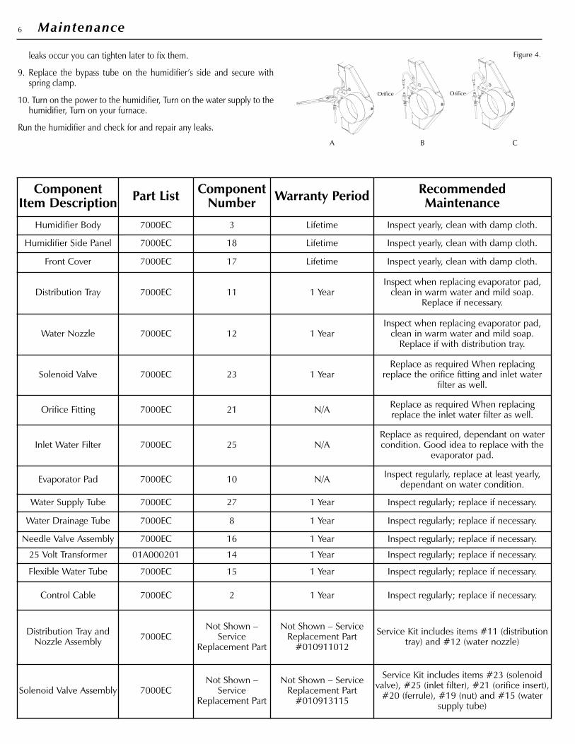
Figure 4.
A B C
ComponentItem Description Part List Component
Number Warranty Period RecommendedMaintenance
Humidifier Body 7000EC 3 Lifetime Inspect yearly, clean with damp cloth.
Humidifier Side Panel 7000EC 18 Lifetime Inspect yearly, clean with damp cloth.
Front Cover 7000EC 17 Lifetime Inspect yearly, clean with damp cloth.
Distribution Tray 7000EC 11 1 Year Inspect when replacing evaporator pad,
clean in warm water and mild soap.Replace if necessary.
Water Nozzle 7000EC 12 1 Year Inspect when replacing evaporator pad,
clean in warm water and mild soap.Replace if with distribution tray.
Solenoid Valve 7000EC 23 1 Year Replace as required When replacing
replace the orifice fitting and inlet waterfilter as well.
Orifice Fitting 7000EC 21 N/A Replace as required When replacingreplace the inlet water filter as well.
Inlet Water Filter 7000EC 25 N/A Replace as required, dependant on watercondition. Good idea to replace with the
evaporator pad.
Evaporator Pad 7000EC 10 N/A Inspect regularly, replace at least yearly,dependant on water condition.
Water Supply Tube 7000EC 27 1 Year Inspect regularly; replace if necessary.
Water Drainage Tube 7000EC 8 1 Year Inspect regularly; replace if necessary.
Needle Valve Assembly 7000EC 16 1 Year Inspect regularly; replace if necessary.
25 Volt Transformer 01A000201 14 1 Year Inspect regularly; replace if necessary.
Flexible Water Tube 7000EC 15 1 Year Inspect regularly; replace if necessary.
Control Cable 7000EC 2 1 Year Inspect regularly; replace if necessary.
Distribution Tray andNozzle Assembly 7000EC
Not Shown –Service
Replacement Part
Not Shown – ServiceReplacement Part
#010911012
Service Kit includes items #11 (distributiontray) and #12 (water nozzle)
Solenoid Valve Assembly 7000EC Not Shown –
ServiceReplacement Part
Not Shown – ServiceReplacement Part
#010913115
Service Kit includes items #23 (solenoidvalve), #25 (inlet filter), #21 (orifice insert),
#20 (ferrule), #19 (nut) and #15 (watersupply tube)
OrificeOrifice
7Maintenance
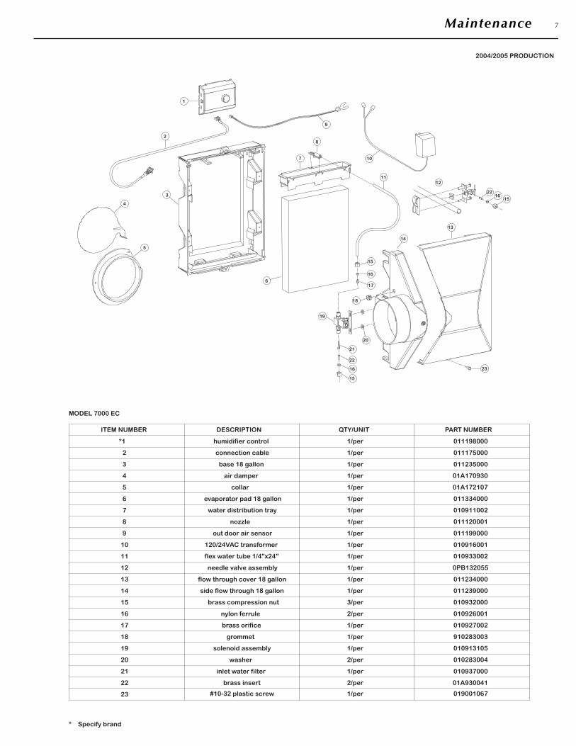
0112350001/perbase 18 gallon3
23
* Specify brand
17
19
22
20
15
16
14
7
11
12
10
5
6
4
8
0109370001/perinlet water filter
#10-32 plastic screw
brass compression nut
nylon ferrule
brass insert
1/per
3/per
2/per
2/per
019001067
010932000
010926001
01A930041
1/per120/24VAC transformer
grommet
washer
solenoid assembly
side flow through 18 gallon
flow through cover 18 gallon
needle valve assembly
flex water tube 1/4"x24"
1/per
2/per
1/per
1/per
1/per
1/per
1/per
nozzle
water distribution tray
evaporator pad 18 gallon
collar
air damper
1/per
1/per
1/per
1/per
1/per
010916001
010913105
010283004
910283003
011239000
011234000
0PB132055
010933002
011120001
010911002
011334000
01A172107
01A170930
MODEL 7000 EC
ITEM NUMBER
*1
2 connection cable
humidifier control
DESCRIPTION
1/per
1/per
QTY/UNIT
011175000
011198000
PART NUMBER
18
brass orifice 1/per 010927002
21
2004/2005 PRODUCTION
9
13
out door air sensor 1/per 011199000
5
4
3
13
15
16
22
21
616
17
19
20
18
23
14
28
7 10
1
1112
1516
22
15
9
TROUBLE SHOOTING GUIDE
PROBLEM: NOT ENOUGH HUMIDITY
POSSIBLE CAUSE: Humidistat set too low.
REMEDY: Turn up the humidistat.
POSSIBLE CAUSE: Humidifier has only been installed for a fewdays.
REMEDY: If you have just installed the humidifier it cantake anywhere from 3 to 4 weeks to build up the humiditylevel in the home.
POSSIBLE CAUSE: Not enough air flow through the humidifier.For the maximum performance of 12 us gallons in 24 hrs ofoperation there must be at least 0.5” static pressure.
REMEDY:
• Adjust bypass damper to fully open position.
• Ensure the bypass tube is fully stretched out tight.
• Furnace filter is dirty and needs replacement.
• Bypass tube and humidifier not installed parallel, use hardducting – use hard ducting for any elbows – take the mostdirect route when ducting.
• The bypass tube or humidifier is installed in front of air-conditioning coils or is blocked in some other way – move toanother location and ensure maximum air flow.
• The humidifier and bypass tube are installed on thesame duct – you must install the unit on either thesupply or return and the bypass tube on the oppositeduct or the unit will not work.
• For some reason your furnace is not supplying sufficientair to the unit.
POSSIBLE CAUSE: Not enough water is getting to the evaporatorpad. For the maximum performance of 12 US gallons in 24 hoursof operation there must be at least 60 PSI of water pressure.
REMEDY:
• Check that the unit is turned on and plugged in.
• Check that the humidistat is turned up and is calling forhumidity. If at the start of the furnace cycle the humidistat isnot calling for humidity then the humidifier will wait until thenext furnace cycle, even if during the furnace cycle thehumidity level drops below the set point.
• Check that the saddle valve is open.
• Check that the unit is level and that the evaporator padassembly is getting evenly wet.
• Check that there is water getting to the humidifier, turn off thewater disconnect the water supply to the unit and turn thewater back on. Allow the water to flow into a bucket,reconnect the water after test.
• Check the amount of water being supplied to the evaporatorpad. (Procedure in Maintenance Guide)
• Check that the water inlet filter is not plugged. Replace ifrequired. (Procedure in Maintenance Guide)
• Check that the black orifice fitting is not plugged. (Procedure inMaintenance Guide)
• The homes water pressure is too low. For rated output thewater pressure must be at least 60 PSI.
POSSIBLE CAUSE: Unit is not cycling with the furnace in heatingmode. For this unit to work it must sense a 4°C temperature riseover 1 minute of time and the air temperature must be at least30°C. This ensures that the humidifier is using water efficiently. Ifyour furnace does not supply the require temperatures you willhave to purchase and install a pressure switch.
REMEDY:
• Check that the unit is turned on and plugged in.
• Check that the humidistat is turned up and is calling forhumidity. If at the start of the furnace cycle the humidistat isnot calling for humidity then the humidifier will wait until thenext furnace cycle, even if during the furnace cycle thehumidity level drops below the setpoint.
• Check that the bypass damper is open and hot air is flowingthrough the humidifier.
• Ensure the bypass tube is fully stretched out tight.
• Furnace filter is dirty and needs replacement.
• Bypass tube and humidifier not installed parallel, use hardducting – use hard ducting for any elbows – take the mostdirect route when ducting.
• The bypass tube or humidifier is installed in front of air-conditioning coils or is blocked in some other way – move toanother location and ensure maximum air flow.
• The humidifier and bypass tube are installed on the same duct– you must install the unit on either the supply or return andthe bypass tube on the opposite duct or the unit will not work.
• For some reason your furnace is not supplying sufficient heat toactivate the unit. If you use a heat pump or a high efficientfurnace you may see this problem, or if your furnace is notworking properly. It will be necessary to purchase a pressureswitch to activate the unit (available through our parts andservice line 1-800-465-7300), or you may have the unit hardwired to your furnace by a HVAC or electrical professional andbypass the unit's control.
POSSIBLE CAUSE: The air going through the unit is not hotenough. For the maximum performance of 18 US gallons in 24hours of operation the air temperature going through the filtershould be 120°F. 100°F=15 US gal/24 hours, 80°F=9 US gal/24hours, etc.
REMEDY:
• Adjust bypass damper to fully open position.
• Ensure the bypass tube is fully stretched out tight.
8 Troubleshooting
• Furnace filter is dirty and needs replacement.
• Bypass tube and humidifier not installed parallel, use hardducting – use hard ducting for any elbows – take the mostdirect route when ducting.
• The bypass tube or humidifier is installed in front of air-conditioning coils or is blocked in some other way – move toanother location and ensure maximum air flow.
• The humidifier and bypass tube are installed on the same duct– you must install the unit on either the supply or return andthe bypass tube on the opposite duct or the unit will not work.
• Your furnace does not supply air hot enough to maximizeoutput. If you use a heat pump or a high efficient furnaceyou may see this problem. You may want to consider theuse of supplemental humidification such as floor or tabletop humidifiers.
POSSIBLE CAUSE: The outside conditions have beenextremely cold -15°C to -20°C for extended periods.During extended periods of extreme cold yourhumidifier is working to replenish the moisture which isbeing lost in the home’s structure, furniture, and otherhousehold items. As the humidifier is working the coldweather is continually drying out the house. Because thetemperature drop outside the water temperature beingsupplied to the unit is also low, a 5°F drop in watertemperature will reduce the output of the unit by asmuch as 15-25%
REMEDY: There is no remedy for this situation – except time.Your humidifier has a stated output. All you can do is ensurethat your unit is working at its peak performance. (See sectionin the instructions.)
All homes bring in outside fresh air – whether throughinfiltration (cracks) or through the use of HRV’s. This isimperative to ensure proper indoor air quality. Theamount of outside air brought in will directly affect thehumidity levels in your home, and the colder that air isthe more moisture it will take from the humidifier.
PROBLEM: HUMIDIFIER IS NOT CYCLING ONWHEN THE FURNACE TURNS ON
There may be a time lag occurring between your furnaceturning on and the humidifier turning on. Anything rangingfrom 60 – 120 seconds is considered acceptable, as the unitis waiting to sense the minimum air temperature required toevaporate water. As well it is waiting for a minimumtemperature rise to occur over a one minute period. This isa safe guard to ensure efficient water use.
POSSIBLE CAUSE: Humidistat is not turned on.
REMEDY: Adjust humidistat.
POSSIBLE CAUSE: Unit is not plugged in.
REMEDY: Plug in unit.
POSSIBLE CAUSE: The air going through the unit is nothot enough. For this unit to work it must sense a 4°Ctemperature rise over 1 minute of time and the airtemperature must be at least 30°C. This ensures that thehumidifier is using water efficiently. If your furnace doesnot supply the require temperatures you will have topurchase and install a pressure switch.
REMEDY:
• Adjust bypass damper to fully open position.
• Ensure the bypass tube is fully stretched out tight.
• Furnace filter is dirty and needs replacement.
• Bypass tube and humidifier not installed parallel, use hardducting – use hard ducting for any elbows – take the mostdirect route when ducting.
• The bypass tube or humidifier is installed in front of air-conditioning coils or is blocked in some other way – move toanother location and ensure maximum air flow.
• The humidifier and bypass tube are installed on the same duct– you must install the unit on either the supply or return andthe bypass tube on the opposite duct or the unit will not work.
• Your furnace does not supply air hot enough to activate thecontrol – you will have to install a flow through pressure switch(through our parts and service line) or bypass the humidifierscontrol and have the unit hardwired to your furnace by anelectrician or hvac professional.
There may be a time lag occurring between your furnace turningon and the humidifier turning on. Anything ranging from 60 to120 seconds is considered acceptable, as the unit is waiting tosense the minimum air temperature required to evaporatewater. As well it is waiting for a minimum temperature rise tooccur over a one minute period. This is a safeguard to ensure theefficient use of water.
PROBLEM: HUMIDIFIER IS NOT CYCLINGOFF WHEN THE FURNACE TURNS OFF
POSSIBLE CAUSE: Temperature set point on the control is not setproperly for your furnace. The control has 4 differenttemperature settings.
REMEDY: Follow the section in the instructions to customize thehumidifier’s control to your furnace’s cycles.
POSSIBLE CAUSE: The temperature in the furnace is notdropping fast enough to activate the control's off cycle. Thecontrol will work on all typical residential furnaceinstallations available today. However if for some reason youhave customized your furnace installation, or are usingvarious supplemental heating apparatus for your home (fireplace – gas or wood, radiant floor, etc.), have made additionsor renovations to your home without up grading your heatingsystem, or have not properly maintained your home’s heatingsystem, it may by necessary to use our pressure switch orhave the unit interlocked with your furnace by an electricalor HVAC professional.
9Troubleshooting
REMEDY:
• Adjust bypass damper to fully open position.
• Ensure the bypass tube is fully stretched out tight.
• Furnace filter is dirty and needs replacement.
• Bypass tube and humidifier not installed parallel, use hardducting – use hard ducting for any elbows – take the mostdirect route when ducting.
• The bypass tube or humidifier is installed in front of air-conditioning coils or is blocked in some other way – move toanother location and ensure maximum air flow.
• The fan delay on your furnace is not set properly and thefurnace fan is shutting off too early when the air is still hot. Youshould discuss with a HVAC professional to have yourfurnace’s fan cycle adjusted so you are maximizing the heatdelivered to your home. If the furnace is not adjusted you willhave to consider the use of a flow through pressure switch(through our parts and service line) or bypass the humidifierscontrol and have the unit hardwired to your furnace by anelectrician or HVAC professional.
• Your furnace is located in an enclosed space like a closet,and as a result the temperature in that space is very hot , thisis not a good condition. Proper ventilation is necessary foryour furnace to operate properly you should consult aHVAC professional. If this is the case you will have toconsider the use of a flow through pressure switch (throughour parts and service line) or bypass the humidifiers controland have the unit hardwired to your furnace by anelectrician or HVAC professional.
• Your furnace is not operating properly and running too hot –consult a HVAC professional.
PROBLEM: THE HUMIDISTAT READING DOES NOTSEEM TO MATCH THE HUMIDITY LEVEL IN THE HOME;
IT IS HIGHER OR LOWER
POSSIBLE CAUSE: Dirty humidistat sensor.
REMEDY: Carefully clean the humidity sensor located at the backof the humidistat. You will have to remove the humidistat from theduct and gently blow on the sensor located at the back of the unit.
POSSIBLE CAUSE: The humidistat is located near a fresh air intake
REMEDY: Fresh outdoor air is sometimes introduced to the homethrough the duct work, if you have located the humidistat nearone of these intakes the humidistat will be giving a false readingtry to relocate the humidistat to another part of the return duct.
PROBLEM: NO WATER GETTING TO THE EVAPORATOR PAD
POSSIBLE CAUSE: Humidistat is not turned up.
REMEDY: Turn up the humidistat.
POSSIBLE CAUSE: The unit is not plugged in.
REMEDY: Plug in the unit.
POSSIBLE CAUSE: The furnace is not in heating mode.
REMEDY: The furnace must be blowing hot air for thisunit to work.
POSSIBLE CAUSE: Water supply is not turned on.
REMEDY: Check to make sure water is flowing from thepiercing valve.
POSSIBLE CAUSE: Water is blocked at either the water inlet filteror at the orifice fitting.
REMEDY: Check both components to ensure no blockage exists.
POSSIBLE CAUSE: Solenoid valve is not working.
REMEDY: Replace the solenoid valve.
PROBLEM: THERE IS TOO MUCH WATERGOING DOWN THE DRAIN
POSSIBLE CAUSE: The unit is installed improperly and is notperforming efficiently.
REMEDY: Check your installation in the appropriate section inthe instructions and make any necessary adjustments.
POSSIBLE CAUSE: The unit is working properly and thefurnace is supplying the proper conditions – just not happywith the water usage.
REMEDY: Flow thru humidifiers will use water. This unit has anorifice fitting which meters the amount of water used. A total ofapprox 56 US gallons will be used in 24 hours of operation. – 24hours of operation could take as much as 3 days to completedepending on how often your furnace cycles on. Whencompared to the average shower which uses approx. 5 gallonsper minute. The amount of water used to humidifier your homeis not that much.
PROBLEM: TOO MUCH HUMIDITY IN THE HOME
POSSIBLE CAUSE: Humidistat set too high.
REMEDY: Turn humidistat down.
POSSIBLE CAUSE: Humidistat in Automatic mode and outdoorair sensor is sensing a source of heat.
REMEDY: The outdoor air sensor will adjust the humidity levelbased on outdoor air temperatures, if it is sensing air from a dryervent or exhaust fan vent then it will provide false readings. –move sensor location.
10 Troubleshooting
POSSIBLE CAUSE: Secondary humidity sources.
REMEDY: Humidity levels vary greatly from home to home – thetime of year your home was built will affect the levels – theamount of showers taken, cooking, the amount of ventilation ahome has, as well the amount of people living in a home willaffect the humidity level – turn the humidistat down or turn offthe humidifier until required.
PROBLEM: SOLENOID VALVE BUZZING OR HUMMING
POSSIBLE CAUSE: The 6” spring clamp used to hold the bypasstube is touching the valve.
REMEDY: Adjust the position of the 6” spring clamp so the valvedoes not buzz or hum.
POSSIBLE CAUSE: Loose screws holding the solenoid valve.
REMEDY: Tighten the screws.
POSSIBLE CAUSE: The humidifier body is not secured to thefurnace duct properly.
REMEDY: Ensure all 4 screws which hold the humidifier body inplace are installed and are tightened.
POSSIBLE CAUSE: Using a copper water supply tube.
REMEDY: If using copper water tube ensure it is not touchingsome part of the furnace – you may have to use cushioned pipeclamps to stop humming or buzzing. We recommend that youuse the supplied plastic water supply tube.
POSSIBLE CAUSE: No water is present at the valve.
REMEDY:
• Ensure the water supply valve is open and supplying waterto the unit.
• Check there is no blockage of the inlet filter or orifice fitting.
PROBLEM: LEAKING WATER
POSSIBLE CAUSE: Water connection not tight.
REMEDY: Tighten water connections..
POSSIBLE CAUSE: Flexible water supply tube to the humidifier’sdistribution tray not installed.
REMEDY: Check water supply tube and install correctly.
POSSIBLE CAUSE: Water supply tube has a leak.
REMEDY: Check the condition of the hose and replaceif necessary.
POSSIBLE CAUSE: Evaporator pad assembly is not installedcorrectly.
REMEDY: Check pad and install correctly.
POSSIBLE CAUSE: Air Flow through the unit is too great andwater is blowing off evaporator pad or blowing from underneathevaporator pad.
REMEDY: Close the bypass damper until problem is resolved.
Notes
11Troubleshooting
FLOW-THROUGHFURNACE HUMIDIFIERInstallationWarrantyMaintenanceTroubleshooting Guide
MODEL AK5000 AK5500 & AK7000 SUPPLEMENTAL INSTRUCTION SHEET
WARNING: THIS UNIT IS INTENDED TO BE INSTALLED BY AN LICENCED HVAC PROFESSIONAL – FOR THIS UNIT TO OPERATE PROPERLY THE SUPPLIED 24 VOLT TRANSFORMER MUST BE INTERLOCKED WITH THE
FURNACE HEATING CYCLE – THE 24 VOLT TRANSFORMER SHOULD BE ENERGIZED ONLY WHEN THE FURNACE IS IN HEATING CYCLE. THIS UNIT WILL NOT OPERATE PROPERLY AND YOU RISK DAMAGE UNLESS YOU
PROPERLY INSTALL THE TRANSFORMER. DO NOT ATTEMPT TO COMPLETE THIS INSTALLATION UNLESS YOU ARE A LICENCED HVAC PROFESSIONAL.
TRANSFORMER - MODEL AK5000, AK5500, AK7000• Hazardous Voltage Can Cause Personal Injury Or Equipment Damage. • Disconnect Power Supply Before Installing or Servicing. • On Multispeed Blower Applications, Do Not Wire The High Voltage Side Of The Transformer To The Same Power
Source That Services The Furnace Blower Or The Transformer May Burn Out Prematurely. • Do Not Attempt to Install the transformer unless you are an HVAC professional.
The transformer supplied with the unit is different then indicated in the supplied Installation/operating instructions. You havebeen supplied with a Class 2 120Volt/24 VAC hard wire transformer. It is designed to be connected to the furnace through the furnace accessory terminals, the furnace heating relay, or interlocked with the furnace blower. Install the transformer onthe outside of a grounded metal junction box using only a 7/8” knockout hole. Secure the transformer in place using the locking nut on the transformer mounting sleeve.
HUMIDISENSE HUMIDIFIER CYCLING CONTROL - MODEL AK5000, AK5500, AK7000In the supplied installation/operating instructions reference is made to the electronic “Humidisense” humidifier cycling control,and indicating LED’s. Because models AK5000, AK5500, & AK7000 are contractor installed units, with the transformer interlocked with the furnace’s heating cycles the electronic controls and accompanying LED’s are not required or installed on the units. Your furnace humidifier will automatically cycle ON & OFF when your furnace cycles, no adjustments are required.
ELECTRONIC HUMIDISTAT CONTROL MANUAL AND AUTOMATIC OPERATION - MODEL AK7000In the supplied Model 7000 installation/operating instructions & maintenance/warranty booklets reference is made to the electronic humidistat control with manual and automatic operation. This control is not supplied with the contractor model AK7000, in its place your unit has been provided with a standard mechanical humidistat design for either duct mount or wall mount installation. Refer to the provided humidistat installation sheet for installation instructions.
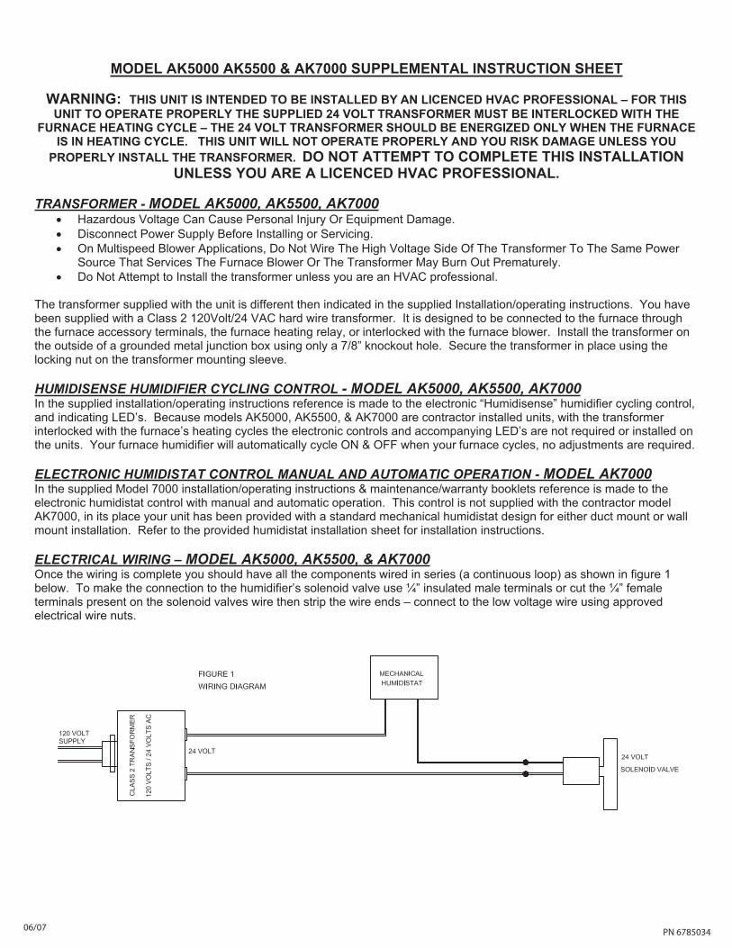
ELECTRICAL WIRING – MODEL AK5000, AK5500, & AK7000Once the wiring is complete you should have all the components wired in series (a continuous loop) as shown in figure 1 below. To make the connection to the humidifier’s solenoid valve use ¼” insulated male terminals or cut the ¼” female terminals present on the solenoid valves wire then strip the wire ends – connect to the low voltage wire using approved electrical wire nuts.
PN 6785034 06/07
FEUILLE D’INSTRUCTION COMPLÉMENTAIRE, MODÈLES AK5000, AK5500 ET AK7000
MISE EN GARDE : CET APPAREIL EST CONÇU POUR ÊTRE INSTALLÉ PAR UN PROFESSIONNEL CVC AUTORISÉ SOUS LICENCE – POUR QUE CET APPAREIL FONCTIONNE CONVENABLEMENT, LE
TRANSFORMATEUR DE 24 VOLTS FOURNI DOIT ÊTRE INTERVERROUILLÉ AVEC LE CYCLE DE CHAUFFAGE DE LA FOURNAISE - LE TRANSFORMATEUR DE 24 VOLTS DEVRAIT ÊTRE MIS SOUS TENSION SEULEMENT
LORSQUE LA FOURNAISE SE TROUVE DANS LE CYCLE DE CHAUFFAGE. CET APPAREIL NE FONCTIONNERA PAS CONVENABLEMENT OU VOUS RISQUEREZ DES DOMMAGES À MOINS QUE LE TRANSFORMATEUR N’AIT ÉTÉ CONVENABLEMENT INSTALLÉ. N’ESSAYEZ PAS DE COMPLÉTER CETTE INSTALLATION À MOINS QUE
VOUS NE SOYEZ UN PROFESSIONNEL CVC AUTORISÉ SOUS LICENCE.
TRANSFORMATEUR – MODÈLES AK5000, AK5500 ET AK7000• La tension dangereuse peut causer des blessures ou des dommages à l’équipement. • Débranchez l’approvisionnement en courant avant de faire l’installation ou l’entretien. • Sur les applications de souffleur à vitesses multiples, ne raccordez pas le côté à haute tension du transformateur
à la même source de courant que celle qui dessert le souffleur de la fournaise, sinon le transformateur risque de se détériorer prématurément.
• N’essayez pas d’installer le transformateur à moins que vous ne soyez un professionnel CVC.
Le transformateur fourni avec cet appareil est différent de celui indiqué dans les instructions fournies d’installation/fonctionnement. Vous avez reçu un transformateur à câblage direct classe 2 de 120 volts/24 VCA. Celui-ci est conçu pour être raccordé à la fournaise au moyen des bornes accessoires de fournaise, du relais de chauffage de fournaise, ou pour être interverrouillé au souffleur de fournaise. Installez le transformateur à l’extérieur d’une boîte de jonction en métal avec mise à la terre en utilisant seulement un trou à pastille défonçable de 7/8 po. Fixez le transformateur en place en utilisant l’écrou de blocage sur le manchon de montage du transformateur.
COMMANDE DE CYCLAGE D’HUMIDIFICATEUR HUMIDISENSE - MODÈLES AK5000, AK5500 ET AK7000Dans les instructions d’installation/fonctionnement fournies, il est fait référence à une commande de cyclage d’humidificateur «Humidisense» électronique et aux DEL d’indication. Étant donné que les modèles AK5000, AK5500 et AK7000 sont des ensembles installés par l’entrepreneur, avec le transformateur interverrouillé aux cycles de chauffage de la fournaise, les commandes électroniques et les DEL les accompagnant ne sont pas nécessaires ni installés sur les ensembles. L’humidificateur de votre fournaise passera automatiquement au cycle de MARCHE ET D’ARRÊT durant les cycles de votre fournaise, aucun ajustement n’est nécessaire.
FONCTIONNEMENT MANUEL ET AUTOMATIQUE DE LA COMMANDE D’HUMIDISTAT ELECTRONIQUE – MODÈLE AK7000Dans le modèle 7000 fourni, les instructions d’installation/fonctionnement et la référence aux livrets d’entretien/garantie sont faites à la commande d’humidistat électronique avec fonctionnement manuel et automatique. Cette commande n’est pas fournie avec le modèle AK7000 de l’entrepreneur, et à sa place votre système a reçu un concept d’humidistat mécanique standard pour installation à montage sur canalisation ou mural. Référez-vous à la feuille d’installation de l’humidistat pour les instructions d’installation.
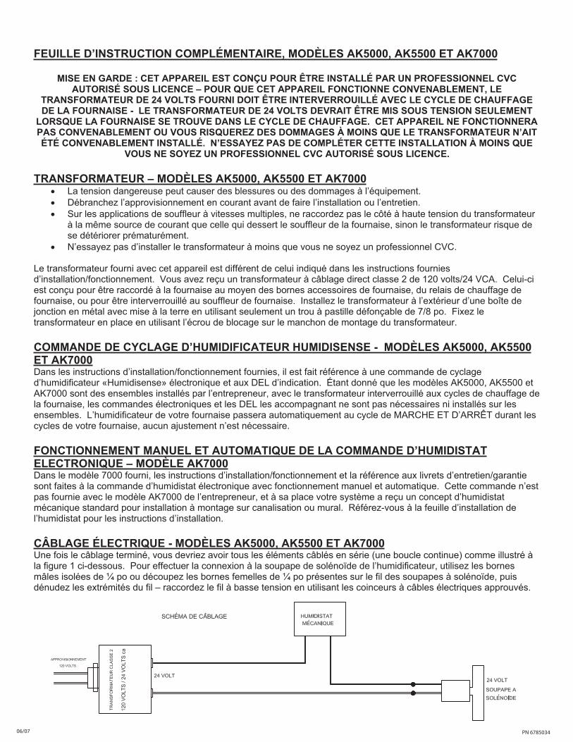
CÂBLAGE ÉLECTRIQUE - MODÈLES AK5000, AK5500 ET AK7000Une fois le câblage terminé, vous devriez avoir tous les éléments câblés en série (une boucle continue) comme illustré à la figure 1 ci-dessous. Pour effectuer la connexion à la soupape de solénoïde de l’humidificateur, utilisez les bornes mâles isolées de ¼ po ou découpez les bornes femelles de ¼ po présentes sur le fil des soupapes à solénoïde, puis dénudez les extrémités du fil – raccordez le fil à basse tension en utilisant les coinceurs à câbles électriques approuvés.
PN 678503406/07