Embed Size (px)
Citation preview

Flow structures around a rectangular cylinder in the vicinity of a wall
J.F. Derakhshandeh1) and *Md. Mahbub Alam2,#)
1) J.F. Derakhshandeh is with School of Mechanical Engineering of University of Adelaide, Australia
2) Md. Mahbub Alam, is with Institute for Turbulence-Noise-Vibration Interaction and Control, Shenzhen Graduate School, Harbin Institute of Technology, Shenzhen 518055,
China #Corresponding author Email: [email protected]
ABSTRACT
A numerical study is conducted on the flow characteristics of a rectangular cylinder (chord-to-width ratio C/W = 2 - 10) mounted close to a rigid wall at gap-to-width ratio G/W = 0.25 - 6.25. The effects of G/W and C/W on the Strouhal number, vortex structure, and time-mean drag and lift forces are examined. The results reveal that both G/W and C/W have strong influences on vortex structure and shear layer instabilities, which significantly affect the forces on the cylinder. An increase in G/W leads to four different flow regimes, namely no vortex street flow (G/W < 0.75), single-row vortex street flow (0.75 ≤ G/W ≤ 1.25), inverted two-row vortex street flow (1.25 < G/W ≤ 2.5), and two-row vortex street flow (G/W > 2.5). Both Strouhal number and time-mean drag are more sensitive to C/W than to G/W. For a given G/W, Strouhal number grows with C/W while time-mean drag decays with C/W, the growth and decay being large between C/W = 2 and 4. The time-mean drag is largest in the single-row vortex street regime, contributed by a large pressure on the front surface, regardless of C/W. A higher C/W, in general, leads to a higher time-mean lift. Maximum time-mean lift occurs for C/W = 10 at G/W = 0.75, while minimum time-mean lift appears for C/W = 2 at the same G/W. The impact of C/W on time-mean lift is more substantial in single-row vortex regime. The effect of G/W on time-mean lift is larger at a larger C/W.
Keywords: Boundary layers, rectangular cylinder, Strouhal number, vortex shedding frequency.
1. INTRODUCTION In this paper, a laminar flow past 2D rectangular cylinders located in the vicinity of
a wall is investigated. For the chosen test cases different chord-to-width (C/W) and gap ratios (G/W) are considered. This problem has associated in many industrial applications such as wind engineering, civil engineering, and heat transfer in electronic equipment.
The flow around a circular cylinder has been extensively studied experimentally and numerically during the past decades (Bearman 1984, Parkinson 1989, Zdravkovich 1997, Norberg 2001, Norberg 2003, Williamson and Govardhan 2004, Alam and Kim 2009, Alam 2014, Derakhshandeh, Arjomandi et al. 2014, Derakhshandeh et al. 2014, Derakhshandeh et al. 2015, Alam 2016, Derakhshandeh et al. 2016). Alternating vortex
shedding occurs from the cylinder when the Reynolds number Re (= < 150) is sufficiently high, Re > 50, where U is the freestream velocity, D is the diameter and is kinematic viscosity of the flowing fluid. The shedding frequency is normalized as
Strouhal number St = , where is the vortex shedding frequency.
A number of studies have been carried out on a rectangular cylinder subjected to a uniform flow. The flow structure over a rectangular cylinder is quite different from that over a circular cylinder because of the difference in the flow separation mechanism, separation being oscillating for the circular cylinder and fixed for the rectangular cylinder (Mills et al. 2002; Alam et al. 2002; Zheng and Alam 2017). The separation mechanism impacts on the shedding frequency as well as aerodynamic forces (Alam et al. 2011). The flow structure and dynamic behaviour of vortices from a rectangular can also be altered by changing the chord-to-width ratio C/W of the rectangular cylinder (Hourigan et al. 2001, Mills et al. 2003). The associated fluid dynamics become more complex for a cylinder mounted in a vicinity of a rigid wall, as the wall-to-cylinder gap ratio G/W gets involved in the flow.
A circular cylinder mounted in the vicinity of a rigid wall undergoes a number of different fluidic instabilities. Many of the previous investigations were conducted on the flow over a circular cylinder at relatively high Re, whereas the fluidic parameters of the flow are comparatively less sensitive to Re (Price et al. 2002, Re = 1200-4960; Sarkar and Sarkar 2010, Re =1440; Derakhshandeh et al. 2014a, Re = 8700). Similar studies have been conducted on the flow around square cylinders, again at high Re (Durao
1991, Re = 1.36 104, Bosch et al. 1996, Re = 2.2 104, Martinuzzi et al. 2003, Re = 1.89 104). Finite Volume (FV) analysis performed by Sohankar et al. (1999) identified two modes, known as Modes A and B, have been identified in their numerical
simulations. Martinuzzi et al. (2003) at Re = 1.89 104 measured time-mean and fluctuating surface pressure on a square cylinder with G/W varying from 0.07 to 1.6. The flow and the vortex shedding strength are similar to the no-wall case for G/W > 0.9. For 0.3<G/W<0.9, the wall exerts a greater influence on the flow. The mean drag and the strength of the shed vortices decrease as G/W is reduced from 0.9 to 0.6. The circulation of vortices in the wake of the square cylinder is found to be directly related to the periodic loading of the cylinder. On the other hand, for G/W< 0.3D, the periodic activity of the flow is fully suppressed in the near wake region.
Mills et al. (2003) performed a series of particle image velocimetry measurements in a closed loop water channel for flow around a rectangular cylinder at Re = 490. The results revealed that the growth of vortices at the trailing edge was weaker as

compared with the leading edge vortices. This is due to the interaction of the trailing and leading edge vortices, which are generated at a similar phase in the perturbation cycle. Vortex shedding from rectangular cylinders of C/W = 2 - 16 in has been experimentally investigated by Nakamura et al. (1991). It was found that the Strouhal number was approximately constant at 0.6 for C/W = 3-5. Nakamura et al. (1991) also showed that a further increase in C/W causes an increment in St, which was equal to integral multiples of 0.6. Later, the relationship between the C/W and St has been numerically confirmed by Tan et al. (2004).
A number of studies have been conducted on flow over circular and square cylinders at high Re. Some selected are presented in Table 1, highlighting the critical G/W below which the alternating vortex shedding is suppressed. It is seen that for the most of the studies, the critical gap ratio arranges between 0.3 and 0.5. However, studies on a square or rectangular cylinder at low Re are very limited.
Table 1. Selected studies on flow over circular and square cylinders highlighting the
critical G/W.
Two and three-dimensional numerical studies were conducted by Mahir (2009) at
Re = 175-250 for the flow over a square cylinder near a wall. The effect of G/W was considered. It was found that at G/W = 0.5, the Strouhal numbers for both two and three-dimensional models are similar. The maximum lift and drag coefficients were achieved for G/W < 1. Mahir (2009) did not consider the effect of C/W on the flow or forces.
The objective of this study is to investigate the flow past a rectangular cylinder in the vicinity of the rigid wall in order find the relationship between the Strouhal number, C/W (= 2-10) and G/W (= 0.25-6.25). The vortex structure and forces on the rectangular cylinder at different G/W and C/W are analyzed and presented. A series of numerical simulations of two-dimensional flow over rectangular cylinders is performed for C/W and G/W ranges considered.
Scholars Cylinder Re G/W
Grass et al. (1984) Circular 2.24-4.32 103 0.28, 6 0.25-0.3
Taniguchi and Miyakoshi (1990) Circular 9.4 104 0.34-1.05 0.3-0.9
Buresti and Lanciotti (1992) Circular 8.6-27.7 104 0.1-1.1 0.3
Lei et al. (1999) Circular 13-14.5 103
0.14-2.89 0.5
Sarkar and Sarkar (2010) Circular 1.44 103 0.25-1.0 0.5
Wang et al. (2013) Circular 3-13 103 0.05-2.5 0.3
Durao et al. (1988) Square 13.6 103 0.8 0.35
Bosch et al. (1996) Square 22 103 0.13 0.35-0.5
Wu (1999) Square 23 103 1.5 0.3-0.5
Martinuzzi et al. (2003) Square 18.9 103 0.5 0.3-0.5
Mahir (2009) Square < 250 0.2-4 0.5

2. GOVERNING EQUATIONS AND NUMERICAL METHOD The numerical simulations were modelled in ANSYS Fluent using Lagrangian
solution of two-dimensional Navier-Stokes equations. The solution was based on the second order implicit Finite Volume Method (FVM) to achieve a better approximation as compared with the first order. The governing equations including continuity and momentum for an unsteady viscous laminar fluid flow can be written as,
(2)
(
)
(3)
In Eqs. (2) and (3), x is the direction, u is the velocity component, stands for the density of the fluid, and P denotes the static pressure.
The Computational domain and boundary conditions considered in this study are presented in Fig. 1. The surfaces of both cylinder and wall were set smooth. The boundary conditions applied at the computational domain were defined as: uniform velocity at the inlet boundary, no-slip on the surface of the cylinder and the rigid wall, free-slip on the upper boundary, and zero velocity derivative at the outlet boundary. The thickness of the cylinder W was 8 mm while the gap G between the cylinder and rigid wall was varied as 2 mm, 6 mm, 10 mm, 20 mm and 50 mm, corresponding to G/W = 0.25, 0.75, 1.25, 2.5, 6.25, respectively.
Fig. 1. Computational domain and boundary conditions for the laminar flow around a
rectangular cylinder with constant inlet and outlet temperature in the vicinity of the wall at Re = 200.
The front surface of the cylinder was set 10W away from the inlet boundary (Fig.
1). Therefore, the boundary layer thickness of the flow over the rigid wall can be
estimated as 5x/ that is 28 mm at the front surface of the cylinder. As a result, the cylinder is fully or partially submerged in the boundary layers when G varies from 2 to 20 mm. At G = 50 mm, the cylinder is completely mounted outside of the boundary layers. With keeping W constant, the chord C of cylinder is varied as C/W = 2, 4, 6, 8 and 10. Therefore, a total of 25 simulations are carried out as listed in Table 2.

For all test cases, the Re based on W was 200, chosen to guarantee the vortex street as well as to avoid three-dimensionality in the flow (Tan et al. 2004).
Table 2. Test cases showing values of C/W and G/W.
*Cylinder lying outside the boundary layer.
3. MESH STRUCTURE AND GRID RESOLUTION TESTS
In the numerical models, the structured mesh was generated and used. Four mesh resolutions were examined for one typical test case C/W = 10 (it is the maximum C/W in the computational domain). The method of Grid Convergence Index (GCI) recommended by Celik, et al. (Celik et al. 2008) was exploited to identify that the selected resolution was sufficient to precisely capture the flow characteristics, particularly in boundary layers close to the rigid wall and around the cylinder. Fig. 2 depicts typically structured meshes for the longest C/W with minimum gap ratio (G/W = 0.25). The time step was determined to be 0.002 s, based on the minimum mesh size in order to satisfy the convergence criteria and Courant constraint.
Groups Test
Case
C/W G/W
1 1 2 0.25
2 2 0.75
3 2 1.25
4 2 2.5
5* 2 6.25
2 6 4 0.25
7 4 0.75
8 4 1.25
9 4 2.5
10* 4 6.25
3 11 6 0.25
12 6 0.75
13 6 1.25
14 6 2.5
15* 6 6.25
4 16 8 0.25
17 8 0.75
18 8 1.25
19 8 2.5
20* 8 6.25
5 21 10 0.25
22 10 0.75
23 10 1.25
24 10 2.5
25* 10 6.25

Fig. 2. A typical two-dimensional structured mesh around a rectangular cylinder with
C/W = 10 and G/W = 0.25.
Table 3 summarizes St, time-mean drag (D
C ) and rms lift coefficient (CL,rms) as a
function of grid number ( . The results reveal that St, DC and CL,rms converge for
Mesh case 3 ( ), with a percentage of error of 1%, 1.6% and 1.5%, respectively. Hence, for the rest of the simulations, MC3 is chosen.
Table 3. Typical mesh refinement test for C/T = 10 and G/W = 0.25.
Mesh Case
Mesh quality St %
error CL,rms % error DC
% error
Very Coarse 38,688 1.810 6.2 % 0.101 15.8 % 0.175 9.7 %
Coarse 49,746 1.870 3.1 % 0.108 10.0 % 0.186 4.1 %
Refined 57,211 1.910 1.0 % 0.118 1.6 % 0.191 1.5 %
Highly refined
61,442 1.930 --- 0.120 --- 0.194 ---
4. RESULTS AND DISCUSSION 4.1. REPRODUCTION OF STROUHAL NUMBER FOR UNBOUNDED CYLINDER
In order to further verify the numerical results, the laminar flow around unbounded cylinders of different C/W was considered, and the variation of Strouhal number is compared in Fig. 3. Here Stc represents the Strouhal number based on C. Typical power spectra of the lift forces as a function of C/W are illustrated in Fig. 3(a). The power spectra reveal that an increase in C/W leads to a jump in Stc step-by-step. With
Stc = 0.35 at C/W = 2, Stc jumps between C/W = 2 and 3, lying constant at 0.55 over C/W = 4-5. The Stc leaps to higher values with a further increase in C/W, which are almost equal to integral multiples of 0.55. Numerical investigations conducted by Tan et al. (2003) for the flow around a rectangular cylinder revealed that Stc can be formulated as Stc = 0.55n. Here, the “n” is an integer number and stands for the number of vortices along the rectangular cylinder. The results demonstrate that the Stc’s for all test cases are in good agreement with the previous numerical studies.

Fig. 3. (a) Power spectra of lift force for typical C/W, and (b) dependence of Stc on C/W.
4.2. VORTEX SHEDDING IN THE WAKE OF THE CYLINDER
Figures 4 and 5 show dependence of G/W on typical vorticity structures at C/W =
6 and 10, respectively. Vorticity contours represent a comprehensive physical behavior of the flow and vortex pattern, which is always accompanied by a physical alteration in the flow. For instance, it causes a pressure fluctuation and a flow velocity alteration around and in the near wake of the cylinder (Derakhshandeh et al. 2014b). At G/D = 0.25 (Fig. 4a), there is no vortex shedding from the cylinder, the shear layers persisting to be stable. A similar observation was made for other C/W (e.g., Fig. 5a). This means that G/W plays more important role than C/W.
At G/W = 0.75 - 1.25, vortex shedding occurs from both freestream side and gap, the feature being different from that for G/W = 0.25 (Fig. 4b, c). In the gap, two boundary layers are developed, one by the wall and the other by the lower surface of the cylinder, generating two counter-rotating vortices behind the cylinder. The positive-signed vortices originating from the lower surface of the cylinder are elongated outwards as a jet flow. On the other hand, the upper shear layer reattaches near the trailing edge of the cylinder, shedding negative-signed vortices. The vortices from the upper side of the cylinder manifest themselves and interact with vortices from the gap. Having a higher velocity because of the jet like flow from the gap, the two vortices from the gap approach the vortex from the upper shear layer and interact. Because of having the same-sign of vorticity, the vortices from the upper side and wall merge (Fig. 4c). The merged vortex thus gets bigger in size. As the positive-signed vortex shed from the lower surface lies between the vortices from the wall and lower surface, it elongates and moves to the freestream side due to the clockwise rotation of the merged vortex. The elongated vortices decay rapidly and lose their identities downstream. A single-row vortex street thus characterizes the wake.
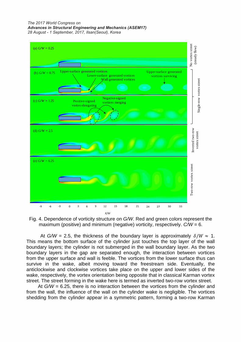
Fig. 4. Dependence of vorticity structure on G/W. Red and green colors represent the
maximum (positive) and minimum (negative) vorticity, respectively. C/W = 6.
At G/W = 2.5, the thickness of the boundary layer is approximately 1. This means the bottom surface of the cylinder just touches the top layer of the wall boundary layers; the cylinder is not submerged in the wall boundary layer. As the two boundary layers in the gap are separated enough, the interaction between vortices from the upper surface and wall is feeble. The vortices from the lower surface thus can survive in the wake, albeit moving toward the freestream side. Eventually, the anticlockwise and clockwise vortices take place on the upper and lower sides of the wake, respectively, the vortex orientation being opposite that in classical Karman vortex street. The street forming in the wake here is termed as inverted two-row vortex street.
At G/W = 6.25, there is no interaction between the vortices from the cylinder and from the wall, the influence of the wall on the cylinder wake is negligible. The vortices shedding from the cylinder appear in a symmetric pattern, forming a two-row Karman
(a) G/W = 0.25
(b) G/W = 0.75
(c) G/W = 1.25
(d) G/W = 2.5
(e) G/W = 6.25
Lower-surface generated vortices
Upper-surface generated vortices Upper-surface generated
vortices surviving
Negative-signed
vortices mergingPositive-signed
vortex elongating
Wall generated vortices
No
vo
rtex
str
eet
(ste
ad
y flo
w)
Sin
gle
-ro
w v
ort
ex
str
eet
Inv
ert
ed
tw
o-r
ow
vo
rtex
str
eet
Tw
o-r
ow
vo
rtex
str
eet

vortex street. A similar observation is made for C/W = 10 (Fig. 5), albeit the influence of C/W cannot be neglected. For example, at G/W = 0.75 and 1.25, while vortices from the wall boundary layer and cylinder lower-side boundary layer for C/W = 6 are comparable to each other (Fig. 4), vortex from the wall for C/W = 10 is weaker than that from the cylinder.
Fig. 5. Dependence of vorticity structure on G/W. Red and green colors represent the
maximum (positive) and minimum (negative) vorticity, respectively. C/W = 10.
Fig. 6 shows the time series of lift coefficient CL of the cylinder (left column) for C/W = 6, exploring further evidence of the claim made above. While constant for G/W = 0.25, CL after convergence oscillates for G/W = 0.75 due to alternating vortex shedding from the two sides of the cylinder. No peak in the power spectra (right column) is discernible for G/W = 0.25, but a clear peak emerges for G/W = 0.75. Further increasing the gap ratio
(a) G/W = 0.25
(b) G/W = 0.75
(c) G/W = 1.25
(d) G/W = 2.5
(e) G/W = 6.25N
o v
ort
ex
str
eet
(ste
ad
y flo
w)
Sin
gle
-ro
w v
ort
ex
str
eet
Inv
ert
ed
tw
o-r
ow
vo
rtex
str
eet
Tw
o-r
ow
vo
rtex
str
eet

up to G/W = 6.25 not only causes a reduction in the amplitude of the fluctuating CL but also leads to a reduction in the mean CL. The amplitude of CL is maximum at G/W = 0.75 where the gap vortices vigorously interact with the freestream side vortices. With increasing G/W from 0.75, as the interaction gets feeble, the amplitude of CL follows suit.
Fig. 6. Time histories of lift coefficient (left column) and power spectrum of fluctuating
lift (right column). C/W = 6. To gain more insight into the frequency response of the vortices, variations in Stc
as a function of C/W is also plotted in Fig. 7. An unbounded cylinder Stc is also included for a comparison purpose. For all the cases, Stc grows with C/W. The Stc for G/W = 6.25 follows the unbounded cylinder results, implying that the cylinder with G/W behaves an unbounded cylinder regardless of C/W. Interestingly, compared to the counterpart in the unbounded cylinder, Stc is smaller for G/W = 0.75 but larger for G/W
= 1.25 and 2.5. The Stc for 3 C/W 8 at G/W = 1.25 and 2.5 is approximately 20-30% (depending on C/W) higher than that of the unbounded cylinder.
Stc

Fig. 7. Variation in the Strouhal number as a function of C/W and G/W.
Fig. 8. Effect of G/W on Strouhal number at different C/W.
0 2 4 6 8 10 12 14
0
0.2
0.4
0.6
0.8
1
1.2
1.4
1.6
1.8
2
C/W
St c
G/W = 0.75
G/W = 1.25
G/W = 2.5
G/W = 6.25
Unbounded cyl.
0 1 2 3 4 5 6 70
0.2
0.4
0.6
0.8
1
1.2
1.4
1.6
1.8
2
G/W
St c
No
vo
rtex
str
eet
Sin
gle
-ro
w
vo
rtex
str
eet
Inver
ted
tw
o-r
ow
vo
rtex
str
eet
Two-row vortex
street
C/W = 2
C/W = 4
C/W = 6
C/W = 8
C/W = 10
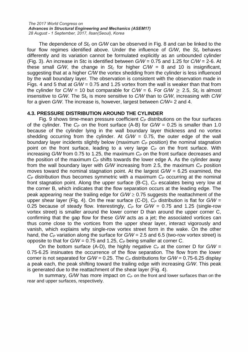
The dependence of Stc on G/W can be observed in Fig. 8 and can be linked to the four flow regimes identified above. Under the influence of G/W, the Stc behaves differently and its variation cannot be formulated explicitly as an unbounded cylinder (Fig. 3). An increase in Stc is identified between G/W = 0.75 and 1.25 for C/W = 2-6. At these small G/W, the change in Stc for higher C/W = 8 and 10 is insignificant, suggesting that at a higher C/W the vortex shedding from the cylinder is less influenced by the wall boundary layer. The observation is consistent with the observation made in Figs. 4 and 5 that at G/W = 0.75 and 1.25 vortex from the wall is weaker than that from
the cylinder for C/W = 10 but comparable for C/W = 6. For G/W 2.5, Stc is almost insensitive to G/W. The Stc is more sensitive to C/W than to G/W, increasing with C/W for a given G/W. The increase is, however, largest between C/W= 2 and 4.
4.3. PRESSURE DISTRIBUTION AROUND THE CYLINDER
Fig. 9 shows time-mean pressure coefficient CP distributions on the four surfaces of the cylinder. The CP on the front surface (A-B) for G/W = 0.25 is smaller than 1.0 because of the cylinder lying in the wall boundary layer thickness and no vortex shedding occurring from the cylinder. At G/W = 0.75, the outer edge of the wall boundary layer incidents slightly below (maximum CP position) the nominal stagnation point on the front surface, leading to a very large CP on the front surface. With increasing G/W from 0.75 to 1.25, the maximum CP on the front surface decreases and the position of the maximum CP shifts towards the lower edge A. As the cylinder away from the wall boundary layer with G/W increasing from 2.5, the maximum CP position moves toward the nominal stagnation point. At the largest G/W = 6.25 examined, the CP distribution thus becomes symmetric with a maximum CP occurring at the nominal front stagnation point. Along the upper surface (B-C), CP escalates being very low at the corner B, which indicates that the flow separation occurs at the leading edge. The
peak appearing near the trailing edge for G/W 0.75 suggests the reattachment of the upper shear layer (Fig. 4). On the rear surface (C-D), CP distribution is flat for G/W = 0.25 because of steady flow. Interestingly, CP for G/W = 0.75 and 1.25 (single-row vortex street) is smaller around the lower corner D than around the upper corner C, confirming that the gap flow for these G/W acts as a jet; the associated vortices can thus come close to the vortices from the upper shear layer, interact vigorously and vanish, which explains why single-row vortex street form in the wake. On the other hand, the CP variation along the surface for G/W = 2.5 and 6.5 (two-row vortex street) is opposite to that for G/W = 0.75 and 1.25, CP being smaller at corner C.
On the bottom surface (A-D), the highly negative CP at the corner D for G/W = 0.75-6.25 insinuates the occurrence of the flow separation. The flow from the lower corner is not separated for G/W = 0.25. The CP distributions for G/W = 0.75-6.25 display a peak each, the peak shifting toward the trailing edge with increasing G/W. This peak is generated due to the reattachment of the shear layer (Fig. 4).
In summary, G/W has more impact on CP on the front and lower surfaces than on the
rear and upper surfaces, respectively.

Fig. 9. Time-mean pressure coefficient CP on the surfaces of cylinder. C/W = 0.6.
4. 4. LIFT AND DRAG FORCES
The effect of G/W on the pressure distribution around the cylinder was studied in
the previous section. The surface pressure can be suitably highlighted through the drag and lift forces. Consequently, in this section, the drag and lift coefficients are studied and evaluated.
The dependence on G/W of time-mean drag coefficient D
C for different C/W is
illustrated in Fig. 10(a). Again the flow regimes are marked in the figure. In the no
vortex street regime, D
C for a given C/W is small and sharply increases with G/W. D
C
becomes maximum in the single-row vortex street regime where the interaction between the upper side and gap vortices is the strongest. Due to the weakening
interaction, D
C declines with G/D in inverted two-row vortex street and two-row vortex
street regimes. Interestingly, given the same G/W, an increase in C/W corresponds to a
decrease in D
C . The decrease is however very large between C/W = 2 and 4.
The effect of G/W on the time-mean lift coefficient L
C is presented in Fig. 12(b). In
general, a higher C/W corresponds to a higher L
C in the no vortex, single-row vortex
and inverted two-row vortex street regimes. Maximum L
C however prevails at C/W =
10, G/W = 0.75. At this G/W, this maximum value tappers off with decreasing C/D,
getting minimum for C/W = 2.0. At the higher G/W examined, L
C is almost
independent of C/W. Interestingly, the influence of C/W is more substantial in the
single-row vortex regime, for instance, at G/W = 0.75,2/10/
][5.10][
WCLWCL
CC . On the
other hand, the effect of G/W is the greatest for C/W = 10.

Fig. 10. Variations in (a) mean drag coefficient
DC and (b) time-mean lift coefficient
LC as a function of G/W and C/W.
No
vo
rtex
str
eet
Sin
gle-
row
vo
rtex
str
eet
Inve
rted
tw
o-r
ow
vort
ex s
tree
t
Tw
o-r
ow
vo
rtex
str
eet
(a)
(b)
LC
DC

5. CONCLUSIONS A 2D laminar flow past a rectangular cylinder mounted in a vicinity of a rigid wall is
simulated to study the physical feature of the flow at Re = 200 based on W. Chord-to-width ratios (C/W) for the rectangular cylinder is varied from 2 to and the gap spacing ratio (G/W) between the cylinder and wall is changed from 0.25 to 6.25. The results reveal that both G/W and C/W have strong influences on vortex structure and shear layer instabilities which significantly affect the forces imposing on the cylinder. As such four different flows are identified based on the dynamic behaviour of the vortices, i.e., no vortex street flow, single-row vortex street flow, inverted two-row vortex street flow, and two-row vortex street flow. The no vortex street flow occurring at G/W < 0.75 is steady, no vortices generated in the wake. The single-row vortex flow (0.75 ≤ G/W ≤ 1.25) features a single row of negative vortices. Two opposite-signed vortices (one by the wall and the other by the lower surface of the cylinder) from the gap come into being against one vortex shed from the upper surface in one period. The vortex from the wall merges with that the upper surface, forming a combined vortex. The vortex from the lower surface of the cylinder exhausts because of a strong interaction with the vortices from the wall and upper surface. The combined vortices thus surviving in the wake generate a single-row street. In inverted two-row vortex street flow (1.25 < G/W ≤ 2.5), the interaction between the lower surface vortex and the upper surface vortex and/or wall vortex is feeble. The vortices from the lower surface thus can survive, moving toward the freestream side. The upper and lower surface vortices take position oppositely in the wake, forming an inverted two-row vortex street. The two-row vortex street flow appearing at G/W > 2.5 is characterized by a vortex street of 2S type where the upper and lower surface vortices take positions in the upper and lower sides of the wake, respectively. The interaction between the vortices from the cylinder and from the wall is negligible.
The presence of the wall significantly influences the Strouhal number in the single-row and inverted two-row vortex streets. The Strouhal number is highly dependent on C/W, increasing with C/W. The increase is largest between C/W= 2 and 4. The Strouhal number for G/W = 6.25 follows that of the unbounded cylinder, regardless of C/W. Compared to the counterpart in the unbounded cylinder, Strouhal number is smaller for G/W = 0.75 but larger for G/W = 1.25 and 2.5. The Strouhal
number for 3 C/W 8 at G/W = 1.25 and 2.5 is approximately 20-30% (depending on C/W) higher than that of the unbounded cylinder. The Strouhal number is more sensitive to C/W than to G/W, increasing with C/W for a given G/W.
Time-mean pressure on the front surface is the largest at G/W = 0.75 in the single-row vortex street flow as the outer edge of the wall boundary layer incidents on the front surface. With increasing G/W from 0.75 to 1.25, the maximum CP on the front surface decreases and the position of the maximum CP shifts towards the lower edge. The pressure on the front and lower surfaces is more sensitive to G/W than that on the
rear and upper surfaces, respectively. Regardless of C/W, D
C is largest in the single-
row vortex street regime, contributed by a large pressure on the front surface. D
C
decays with G/W in inverted two-row vortex street and two-row vortex street regimes.
Given the same G/W, an increased C/W leads to a decreased D
C , the decrease being
very large between C/W = 2 and 4. A higher C/W corresponds to a higher L
C for a

given G/W. Maximum L
C occurs for C/W = 10 at G/W = 0.75, while minimum L
C
appears for C/W = 2 at the same G/W. The impact of C/W is more substantial in the
single-row vortex regime. The effect of G/W on L
C is larger at a larger C/W.
ACKNOWLEDGMENT Alam wishes to acknowledge the support given to them from National Natural
Science Foundation of China through Grants 11672096 and from Research Grant Council of Shenzhen Government through grant JCYJ20160531191442288.
REFERENCES
Alam, M. M. (2014), "The aerodynamics of a cylinder submerged in the wake of another", J. Fluids Struct. 51, 393-400.
Alam, M. M. (2016), "Lift forces induced by phase lag between the vortex sheddings from two tandem bluff bodies", J. Fluids Struct. 65: 217-237.
Alam, M. M. and S. Kim (2009), "Free vibration of two identical circular cylinders in staggered arrangement", Fluid Dynamics Research, 41(3): 035507.
Alam, M. M., Moriya, M., Takai, K. and Sakamoto, H. (2002), "Suppression of fluid forces acting on two square prisms in tandem arrangement by passive control of flow", J. Fluids Struct. 16, 1073-1092.
Alam, M. M., Zhou, Y., and Wang, X.W. (2011), "The wake of two side-by-side square cylinders", J. Fluid Mech. 669, 432-471.
Zheng, Q., and Alam, M.M., (2017), "Intrinsic features of flow past three square prisms in side-by-side arrangement", J. Fluid Mech. (in press).
Bearman, P. W. (1984), "Vortex shedding from oscillating bluff bodies", Ann. Rev. Fluid Mech. 16(1): 195-222.
Bosch, G., M. Kappler and W. Rodi (1996), "Experiments on the flow past a square cylinder placed near a wall", Exp. Ther. fluid Sc. 13(3): 292-305.
Buresti, G. and A. Lanciotti (1992), "Mean and fluctuating forces on a circular cylinder in cross-flow near a plane surface", J. Wind Eng. Indust. Aerodyn. 41(1-3): 639-650.
Celik, I. B., U. Ghia and P. J. Roache (2008), "Procedure for estimation and reporting of uncertainty due to discretization in CFD applications", J. Fluids Eng., Trans. ASME 130(7).
Derakhshandeh, J., M. Arjomandi, B. Cazzolato and B. Dally (2015), "Harnessing hydro-kinetic energy from wake-induced vibration using virtual mass spring damper system", Oean Eng.108: 115-128.
Derakhshandeh, J., M. Arjomandi, B. Dally and B. Cazzolato (2016), "Flow-induced vibration of an elastically mounted airfoil under the influence of the wake of a circular cylinder", Exp. Ther. fluid Sc. 74: 58-72.
Derakhshandeh, J. F., M. Arjomandi, B. S. Cazzolato and B. Dally (2014a), "Effect of a rigid wall on the vortex induced vibration of two staggered circular cylinders", J. Renewable and Sustainable Energy 6(3): 033114.

Derakhshandeh, J. F., M. Arjomandi, B. Dally and B. Cazzolato (2014b), "The effect of arrangement of two circular cylinders on the maximum efficiency of Vortex-Induced Vibration power using a Scale-Adaptive Simulation model", J. Fluids Struct. 49: 654-666.
Durao, D., M. Heitor and J. Pereira (1988), "Measurements of turbulent and periodic flows around a square cross-section cylinder", Exp. Fluids 6(5): 298-304.
Grass, A., P. Raven, R. Stuart and J. Bray (1984), "The influence of boundary layer velocity gradients and bed proximity on vortex shedding from free spanning pipelines", J. Energy Resources Technology 106(1): 70-78.
Hourigan, K., M. Thompson and B. Tan (2001), "Self-sustained oscillations in flows around long blunt plates", J. Fluids Struct. 15(3-4): 387-398.
Lei, C., L. Cheng and K. Kavanagh (1999), "Re-examination of the effect of a plane boundary on force and vortex shedding of a circular cylinder", J. Wind Eng. Indust. Aerodyn. 80(3): 263-286.
Mahir, N. (2009), "Three-dimensional flow around a square cylinder near a wall", Oean Eng. 36(5): 357-367.
Martinuzzi, R., S. Bailey and G. Kopp (2003), "Influence of wall proximity on vortex shedding from a square cylinder", Exp. Fluids 34(5): 585-596.
Mills, R., J. Sheridan and K. Hourigan (2002), "Response of base suction and vortex shedding from rectangular prisms to transverse forcing", J. Fluid Mech. 461: 25.
Mills, R., J. Sheridan and K. Hourigan (2003), "Particle image velocimetry and visualization of natural and forced flow around rectangular cylinders", J. Fluid Mech. 478: 299.
Nakamura, Y., Y. Ohya and H. Tsuruta (1991), "Experiments on vortex shedding from flat plates with square leading and trailing edges", J. Fluid Mech. 222: 437-447.
Norberg, C. (2001), "Flow around a circular cylinder: aspects of fluctuating lift", J. Fluids Struct. 15(3-4): 459-469.
Norberg, C. (2003), "Fluctuating lift on a circular cylinder: review and new measurements", J. Fluids Struct. 17(1): 57-96.
Ozono, S., Y. Ohya, Y. Nakamura and R. Nakayama (1992), "Stepwise increase in the Strouhal number for flows around flat plates", Int. J. Num. Meth. Fluids 15(9): 1025-1036.
Parkinson, G. (1989), "Phenomena and modelling of flow-induced vibrations of bluff bodies", Prog. Aerospace Sc. 26(2): 169-224.
Price, S., D. Sumner, J. Smith, K. Leong and M. Paidoussis (2002), "Flow visualization around a circular cylinder near to a plane wall", J. Fluids Struct. 16(2): 175-191.
Sarkar, S. and S. Sarkar (2010), "Vortex dynamics of a cylinder wake in proximity to a wall", J. Fluids Struct. 26(1): 19-40.
Sohankar, A., C. Norberg and L. Davidson (1999), "Numerical simulation of flow past a square cylinder", FEDSM99-7172—3rd ASME/JSME Joint Fluids Engineering Conference.
Tan, B., M. Thompson and K. Hourigan (2003), "Sources of acoustic resonance generated by flow around a long rectangular plate in a duct", J. Fluids Struct. 18(6): 729-740.
Taniguchi, S. and K. Miyakoshi (1990), "Fluctuating fluid forces acting on a circular cylinder and interference with a plane wall", Exp. Fluids 9(4): 197-204.

Wang, X., Z. Hao and S. Tan (2013), "Vortex-induced vibrations of a neutrally buoyant circular cylinder near a plane wall", J. Fluids Struct. 39: 188-204.
Williamson, C. and R. Govardhan (2004), "Vortex-induced vibrations", Annu. Rev. Fluid Mech, 36: 413-455.
Wu, K. (1999), "An experimental investigation of the flow around a two-dimensional cylinder in the proximity of a solid wall: effect of the gap size", MESc thesis, Faculty of Engineering Science, The University of Western Ontario, London, Canada.
Zdravkovich, M. (1997), "Flow around circular cylinders; vol. i fundamentals", J. Fluid Mech. 350(1): 377-378.