Embed Size (px)
Citation preview

3/200 Siemens FI 01 · 2015 US Edition
Flow MeasurementSITRANS F C
Flow sensor SITRANS FCS200
3
■ Overview
SITRANS FCS200 (DN10, DN 15 and DN 25) is a Coriolis sensor specialized for accurate mass flow measurement of gases.
The sensor offers superior performance in terms of flow accu-racy and turn down ratio. The ultra compact sensor design makes installation, replacement and commissioning very straight forward and easy.
■ Benefits
• High accuracy gas measurement• Approved for use in hazardous area• DN 10 and DN 15 is custody transfer approved, according to
OIML R 139 (Compressed gaseous fuel measuring systems for vehicles). For custody transfer applications SIFLOW FC070 Ex CT must be used.
• Self-draining in vertical orientation• Pt1000 temperature measurement for optimum accuracy • SENSORPROM enabling true "plug & play"• Rigid enclosure design reducing influence from pipeline vi-
bration and thermal stress• High-pressure measurement up to 350 bar (5076 psi)• Ultra compact sensor design with space-saving split flow
■ Application
SITRANS FCS200 is designed for measurement of gases and is suitable for use in the oil and gas industry:• Filling of gas bottles• CNG dispensers• Metering of general gas applications
■ Design
SITRANS FCS200 is available in DN 10, DN 15 and DN 25.
The sensor consists of 2 parallel measuring pipes, welded di-rectly onto a flow splitter at each end of the sensor to eliminate a direct coupling to the process connectors and significantly re-duce effects from external vibrations. The flow-splitters are welded directly onto a rigid sensor housing which acts as a me-chanical low pass filter.
The SITRANS FCS200 DN 10 and DN 15 wetted parts material is Hastelloy C22, and the DN 25 wetted parts material is AISI 316Ti/1.4571. The enclosure is made of stainless steel AISI 316L/1.4404 with a grade of encapsulation of IP67.
The two black rupture discs are designed to protect theenclosure from overpressure.
■ Function
The flow measuring principle is based on the Coriolis effect. See "System information SITRANS F C".
■ Integration
The complete flowmeter consists of the sensor (SITRANS FCS200) and a transmitter SITRANS F C MASS 6000 or SIFLOW FC070. All communication options are available for MASS 6000.
The sensor is shipped with a SENSORPROM memory unit con-taining all information about calibration data, device identity and factory pre-programming of transmitter settings.
Installation guidelines
Siemens Flow Instruments recommends installing the sensor in one of the following ways:
Vertical orientation with an upwards flow
Horizontal installation, tubes up
Horizontal installation, tubes sideways
FI01_2015_us_Kap03.book Seite 200 Freitag, 20. Februar 2015 10:20 10
© Siemens AG 2015

3/201Siemens FI 01 · 2015 US Edition
Flow MeasurementSITRANS F C
Flow sensor SITRANS FCS200
3
■ Technical specifications
■ Characteristic curves
DN 10
DN 15
DN 25
The pressure drop as a function of capacity for CNG with a pres-sure of 200 bar (2900 psi) and an ambient temperature of 20 °C (68 °F).
Sensor size DN 10 DN 15 DN 25
Mass Flow
Accuracy [% of rate] 0.5
Repeatability [% of rate] 0.25
Max. zero point error [kg/h (lb/h)]
0.25 (0.55) 1.2 (2.65) 3.0 (6.6)
Measuring range [kg/min (lb/min)]
0 … 42 (0 … 92.6)
0 … 200 (0 … 440.9)
0 … 500 (0 … 1102.3)
Process temperature -40 ... +125 °C (-40 ... +257 °F)
Ambient temperature -40 ... +60 °C (-40 ... +140 °F)
Temperature error 0.5 °C (0.9 °F)
Pressure [bar (psi)] 350 (5076) 350 (5076) 214 (3104)
Enclosure grade IP66/IP67 (EN 60529)
Material
Measuring pipe Hastelloy C22/2.4602
Hastelloy C22/2.4602
Stainless steel AISI
316L/1.4571
Splitter Hastelloy C22/2.4602
Stainless steel AISI
316L/1.4571
Stainless steel AISI
316L/1.4571
Enclosure and connection (flanges)
Stainless steel
Connection thread ¼" NPT½" NPT ½" VCO
½" NPT¾" NPT1" NPT¾" VCO
1" NPT1½" NPT 1" VCO
Ex approval
• ATEX II 1/2 G Ex ia IIC T5/T4 Ga/Gb
• IECEx Ex ia IIC T5/T4 Ga/Gb
• FM Class I, Div 1, Groups A, B, C and D
Weight approx. 2.8 kg (6.2 lb)
6.0 kg (13.2 lb)
11 kg (24.2 lb)
Approvals Custodytransfer
DN 10/DN 15 PTB Germany approval nr: 5.4.11/11.22OIML R 139 - Compressed gaseous fuel
measuring systems for vehicles
00
0.5
1.0
1.5
2.0
2.5bar
200 400 600 800 1000 1200 1400 [kg/h]
00
0.4
0.6
0.8
1.0
1.2bar
500 1000 1500 2000 2500 3000 3500 [kg/h]
0.2
00
1.0
1.5
2.0
2.5
3.0
3.5bar
5000 10000 15000 20000 25000 [kg/h]
0.5
FI01_2015_us_Kap03.book Seite 201 Freitag, 20. Februar 2015 10:20 10
© Siemens AG 2015

3/202 Siemens FI 01 · 2015 US Edition
Flow MeasurementSITRANS F C
Flow sensor SITRANS FCS200
3
Accessories
Operating instructions for SITRANS FCS200
Spare parts
Selection and Ordering data Article No.
SITRANS F C Flow sensors
SITRANS FCS200 sensor, without heating jacket
7 ME 4 5 0 0 -
77777 - 7777
Click on the Article No. for the online confi-guration in the PIA Life Cycle Portal.
Sensor size and materialDN 10, Hastelloy C22/2.4602 2 DDN 15, Hastelloy C22/2.4602 2 EDN 25, Stainless steel AISI 316Ti/1.4571 1 F
PressurePN 214 (DN 25) KPN 350 (DN 10 and DN 15) N
Process connection/flange
½“/VCO 7 1¾“/VCO 7 21“/VCO 7 3
¼“/NPT pipe thread 8 1½“/NPT pipe thread 8 2
¾“/NPT pipe thread 8 31“/NPT pipe thread 8 41½“/NPT pipe thread 8 5
ConfigurationStandard 1
Transmitter
None A
CableNo cable A
CalibrationStandard calibration 1
Selection and Ordering data Order code
Additional informationPlease add “-Z“ to Article No. and specify Order code(s) and plain text.
Pressure testing certificate PED: 97/23/EC C11
Material certificate EN 10204-3.1 C12
NDT-Penetrant inspection report ISO 3452 C13
Factory certificate according to EN 10204 2.2 C14
Factory certificate according to EN 10204 2.1 C15
Tag name plate, stainless steel Y17
Description Article No.
Cable with multiple plugStandard blue cable betweenSIFLOW FC070/MASS 6000 andFCS200, 5 x 2 x 0.34 mm2 twisted and screened in pairs. Temperature range -20 °C ... +110 °C(-4 °F ... +230 °F)
5 m (16.4 ft) FDK:083H3015
10 m (32.8 ft) FDK:083H3016
25 m (82 ft) FDK:083H3017
50 m (164 ft) FDK:083H3018
75 m (246 ft) FDK:083H3054
150 m (492 ft) FDK:083H3055
Description Article No.
• English A5E02508199
• German A5E03082574
• Spanish A5E03082587
• French A5E03082581
• Italian A5E03504933
Description Article No.
Multiple plug for cable mounting FDK:083H5056
2 kB SENSORPROM unit(Sensor Serial No. and Article No. must be specified by ordering)
FDK:083H4410
FI01_2015_us_Kap03.book Seite 202 Freitag, 20. Februar 2015 10:20 10
© Siemens AG 2015
3/203Siemens FI 01 · 2015 US Edition
Flow MeasurementSITRANS F C
Flow sensor SITRANS FCS200
3
■ Dimensional drawings
SITRANS FCS200, DN 10 ... DN 15
SITRANS FCS200, DN 10 ... DN 15, dimensions in mm (inch)
Position DN 10 with NPT connectorsmm (inch)
DN 10 with VCO connectorsmm (inch)
DN 15
mm (inch)
(1) 350 (13.78) 330 (12.99) 450 (17.72)
(2) 72 (2.84) 72 (2.84) 72 (2.84)
(3) 100 (3.94) 100 (3.94) 148 (5.83)
(4) 204 (8.03) 204 (8.03) 253 (9.96)
(5) 40 (1.57) 40 (1.57) 48 (1.89)
FI01_2015_us_Kap03.book Seite 203 Freitag, 20. Februar 2015 10:20 10
© Siemens AG 2015

3/204 Siemens FI 01 · 2015 US Edition
Flow MeasurementSITRANS F C
Flow sensor SITRANS FCS200
3
SITRANS FCS200, DN 25
SITRANS FCS200, DN 25, dimensions in mm (inch)
DN 25 - NPT
DN 25 - VCO
Position DN 25 with NPT connectionmm (inch)
DN 25with VCO connectionmm (inch)
(1) 520 (20.47) 550 (21.65)
(2) 72 (2.84) 72 (2.84)
(3) 200 (7.87) 200 (7.87)
(4) 357 (14.77) 357 (14.77)
(5) 74 (2.91) 74 (2.91)
(6) 80 (3.15) 80 (3.15)
(7) 125 (4.92) 125 (4.92)
(8) 32 (1.26) 32 (1.26)
FI01_2015_us_Kap03.book Seite 204 Freitag, 20. Februar 2015 10:20 10
© Siemens AG 2015

3/205Siemens FI 01 · 2015 US Edition
Flow MeasurementSITRANS F C
Flow sensor MASS 2100 DI 1.5
3
■ Overview
MASS 2100 DI 1.5 is suitable for low flow measurement applica-tions of a variety of liquids and gases.
The sensor offers superior performance in terms of flow accu-racy, turn-down ratio and density accuracy. The ease of installa-tion through a "plug & play" mechanical and electrical interface ensures optimum performance and operation.
The sensor delivers true multi-parameter measurements i.e.: Mass flow, volume flow, density, temperature and fraction.
■ Benefits
• High accuracy better than 0.1 % of mass flow rate • Large dynamic turn-down ratio better than 500:1, from 30 kg/h
to a few g/h• Densitometer performance available through a density accu-
racy better than 0.001 g/cm3 with a repeatability better than 0.0002 g/cm3.
• Single continuous tube design, with no internal welds, reduc-tions or flow splitters offers optimal hygiene, safety and CIP cleanability for food and beverage and pharmaceutical appli-cations.
• Market’s biggest wall thickness, ensuring optimal life-time and corrosion resistance and high-pressure durability
• Balanced pipe design with little mechanical energy-loss, en-sures optimal performance and stability under non-ideal and unstable process conditions (pressure, temperature, density-changes etc.).
• 4-wire Pt1000 temperature measurement ensures optimum accuracy on mass flow, density and fraction flow
• Multi-plug electrical connector and SENSORPROM enables true "plug & play". Installation and commissioning in less than 10 minutes
• Intrinsically safe Ex ia design as standard• Sensor pipe available in high-quality stainless steel AISI 316L/
1.4435 or Hastelloy C22/2.4602 offering optimum corrosion re-sistance
• Dual-drive pick-up and driver construction facilitate ultra low-weight pipe construction giving the markets’ smallest and most stable zero point.
• Rugged and space-saving sensor design in stainless steel matching all environments
• High-pressure program as standard• The sensor calibration factor is also valid for gas measurement.
■ Application
In many industries such as the food and beverage or pharam-ceutical industry, accurate recipe control means everything. The MASS 2100 DI 1.5 has demonstrated superiour performance in numerous applications and field trails relating to accuracy and turn-down ratio. It is today the preferred meter for research and development and mini-plant applications for liquid or gas meas-urement, where measuring small quantities is important.
■ Design
The MASS 2100 sensor consists of a single bent tube in a double omega pipe configuration, welded directly to the process con-nectors at each end.
The sensor is available in 2 material configurations, AISI 316L/ 1.4404 or Hastelloy C22/2.4602 with ¼” NPT or ¼” ISO process connections.
The enclosure is made in stainless steel AISI 316L/1.4404 with a grade of encapsulation of IP65/NEMA 4.
The sensor is available in either a standard version with a maxi-mum liquid temperature of 125 °C (257 °F) or a high-tempera-ture version, with raised electrical connector for 180 °C (356 °F).
The sensor can be installed in horizontal or vertical position. The enclosed single quick release clamp fitting which, along with its compact design and single multi-plug electrical connector, will keep installation costs and time to a minimum as shown below.
The main applications for the MASS 2100 DI 1.5 sensor can be found in:
Chemical industry Liquid and gas measurement within Miniplant and R & D, dosing of additives and catalysts
Cosmetic industry Dosing of essence and fragrances
Pharmaceutical industry High-speed dosing and coating of pills, filling of ampuls/injectors
Food and beverage industry Dosing of flavourings, colours and additives, density measurement, inline measurement of liquid or gaseous CO2
Automotive industry Fuel injection nozzle and pump testing, filling of AC units, engine consumption, paint robots, ABS test-beds
FI01_2015_us_Kap03.book Seite 205 Freitag, 20. Februar 2015 10:20 10
© Siemens AG 2015

3/206 Siemens FI 01 · 2015 US Edition
Flow MeasurementSITRANS F C
Flow sensor MASS 2100 DI 1.5
3
■ Function
The measuring principle is based on the Coriolis effect. See “System information SITRANS F C Coriolis mass flowmeters”.
■ Integration
The sensor can be connected to all MASS 6000 transmitters for remote installation only.
All sensors are delivered with a SENSORPROM containing all in-formation about calibration data, identity and factory pre-pro-gramming of transmitter settings
Installation guidelines MASS 2100 DI 1.5 (1/16“)
Installation of MASS 2100 sensor• The optimal installation is horizontal.
If vertical mounting is necessary, upward flow is recom-mended to facilitate the removal of air bubbles. To remove the air from the sensor the flow speed in the sensor must be at least 1 m/s.If there are solid particles in the liquid, especially in connec-tion with low flow, it is recommended that the sensor be mounted horizontally with inlet flange uppermost so that parti-cles are more easily flushed out. To ensure that the sensor does not become partially empty, there must be sufficient counter-pressure on the unit min. 0.2 bar (2.9 psi).
• Mount the sensor on a vibration-free wall or steel frame.• Locate the sensor low in the system in order to avoid an under-
pressure in the sensor separating air/gas in the liquid.• Ensure that the sensor is not emptied of liquid (during normal
operation) otherwise incorrect measurement will occur.
Horizontal
Liquid and gas application
Vertical
Liquid application (left), gas application (right)
■ Technical specifications
1) According to DIN 2413, DIN 174572) Housing is not rated for pressure containment.
For accuracy specifications see “System information SITRANS F C”.
Pressure drop
MASS 2100 DI 1.5 (1/16“), pressure drop for density = 1000 kg/m3
Inside pipe diameter (sensor con-sists of one continuous pipe)
1.5 mm (0.06”)
Pipe wall thickness 0.25 mm (0.010”)
Mass flow measuring range 0 ... 30 kg/h (0 ... 66 lb/h)
Density 0 ... 2.9 g/cm3 (0 ... 0.10 lb/inch3)
Fraction e.g. 0 ... 100 °Brix
Temperature
Standard -50 ... +125 °C (-58 ... +257 °F)
High-temperature version -50 ... +180 °C (-58 ... +356 °F)
Liquid pressure measuring pipe1)
Stainless steel 230 bar (3336 psi) at 20 °C (68 °F)
Hastelloy C22/2.4602 365 bar (5294 psi) at 20 °C (68 °F)
Materials
Measuring pipe and connection Stainless steel AISI 316L/1.4435
Hastelloy C22/2.4602
Enclosure and enclosure material2)
IP65 and stainless steel AISI316L/1.4404
Connection thread
ISO 228/1 G¼” male
ANSI/ASME B1.20.1 ¼” NPT male
Cable connection Multiple plug connection to sen-sor 5 x 2 x 0.35 mm2 twisted and screened in pairs, ext. Ø 12 mm
Ex-version II 1G Eex ia IIC T3-T6, DEMKO 03 ATEX 135252Xc-UL-usEx ia IIC T3-T6UL WYMG.E232147
Weight approx. 2.6 kg (5.73 lb)
Viscosity [cSt]
Mass flow [kg/h]0.1
0.01
0.1
1.0
70101
10
100Δp [bar]
15
1020
50
100
2005001000
FI01_2015_us_Kap03.book Seite 206 Freitag, 20. Februar 2015 10:20 10
© Siemens AG 2015

3/207Siemens FI 01 · 2015 US Edition
Flow MeasurementSITRANS F C
Flow sensor MASS 2100 DI 1.5
3
Operating instructions for SITRANS F C MASS 2100 DI 1.5
This device is shipped with a Quick Start guide and a CD containingfurther SITRANS F literature.
All literature is also available for free at: http://www.siemens.com/flowdocumentation
Accessories
Spare parts
Selection and Ordering data Article No. Ord. code
SITRANS F C Flow sensors 7 ME 4 1 0 0 -
MASS 2100 DI 1.5 (1/16“) sensor 77777 - 7777 777
Click on the Article No. for the online confi-guration in the PIA Life Cycle Portal.
Diameter
Stainless steel AISI 316L/1.4435DI 1.5, max. 125 °C (257 °F) 1 ADI 1.5, max. 180 °C (356 °F) 1 B
Hastelloy C22/2.4602DI 1.5, max. 125 °C (257 °F) 2 ADI 1.5, max. 180 °C (356 °F) 2 B
Pressure
PN 100 DPN 230 (AISI 316L/1.4404) LPN 365 (C22/2.4602) P
Process connection/flange
Pipe thread
G ¼“ male 1 0¼“ NPT male 1 1
Configuration
Standard 1Density 2Brix/Plato 3
Fraction (specification required) 9 N 0 Y
Transmitter compact mounted on sensor
No transmitter, sensor and adapter only A
MASS 6000, Ex d, stainless steel enclosure, 1 current, 1 freq./pulse and 1 relay output, 24 V AC/DC with Ex de [ia/ib] T3 -T6 Ex-approval.
B
MASS 6000, IP67, Polyamide enclosure, cable glands M20, 1 current, 1 freq./pulse and 1 relay output, 24 V AC/DC.
C
MASS 6000, IP67, Polyamide enclosure, cable glands M20, 1 current, 1 freq./pulse and 1 relay output, 115/230 V AC 50/60 Hz
D
MASS 6000, IP67, Polyamide enclosure, cable glands ½" NPT, 1 current, 1 freq./pulse and 1 relay output, 24 V AC/DC
E
MASS 6000, IP67, Polyamide enclosure, cable glands ½" NPT, 1 current, 1 freq./pulse and 1 relay output, 115/230 V AC 50/60 Hz, ½" NPT
F
CableNo cable A5 m (16.4 ft) cable B10 m (32.8 ft) cable C
25 m (82 ft) cable D
50 m (164 ft) cable E75 m (246 ft) cable F
150 m (492 ft) cable G
Calibration
Standard calibration 3 flow x 2 points 1Standard calibration matched pair 3 flow x 2 points
2
Accredited calibration matched pair 5 flow x 2 points (DANAK)
3
Extended calibration customer-specified select Y60, Y61, Y62 or Y63 (see additional information)
8
Selection and Ordering data Order code
Additional informationPlease add “-Z“ to Article No. and specify Order code(s) and plain text.
Pressure testing certificate PED: 97/23/EC C11
Material certificate EN 10204-3.1 C12
Welding certificate NDT-Penetrant: ISO 3452 C13
Factory certificate according to EN 10204 2.2 C14
Factory certificate according to EN 10204 2.1 C15
Tag name plate, stainless steel Y17
Tag name plate, plastic Y18
Customer-specific transmitter setup Y20
Customer-specified, matched pair (5 x 2) Y60
Customer-specified calibration (5 x 2) Y61
Customer-specified, matched pair (10 x 1) Y62
Customer-specified calibration (10 x 1) Y63
Cleaned for oil and grease Y80
Special version Y99
Description Article No.
• English A5E03089952
Description Article No.
Cable with multiple plugStandard blue cable between MASS 6000 and MASS 2100, 5 x 2 x 0.34 mm2 twisted and screened in pairs. Temperature range -20 °C ... +110 °C (-4 °F ... +230 °F)
• 5 m (16.4 ft) FDK:083H3015
• 10 m (32.8 ft) FDK:083H3016
• 25 m (82 ft) FDK:083H3017
• 50 m (164 ft) FDK:083H3018
• 75 m (246 ft) FDK:083H3054
• 150 m (492 ft) FDK:083H3055
Description Article No.
Multiple plug for cable mounting
FDK:083H5056
2 kB SENSORPROM unit(Sensor Serial No. and Article No. must be specified by ordering)
FDK:083H4410
Bracket A5E02590427
FI01_2015_us_Kap03.book Seite 207 Freitag, 20. Februar 2015 10:20 10
© Siemens AG 2015
3/208 Siemens FI 01 · 2015 US Edition
Flow MeasurementSITRANS F C
Flow sensor MASS 2100 DI 1.5
3
■ Dimensional drawings
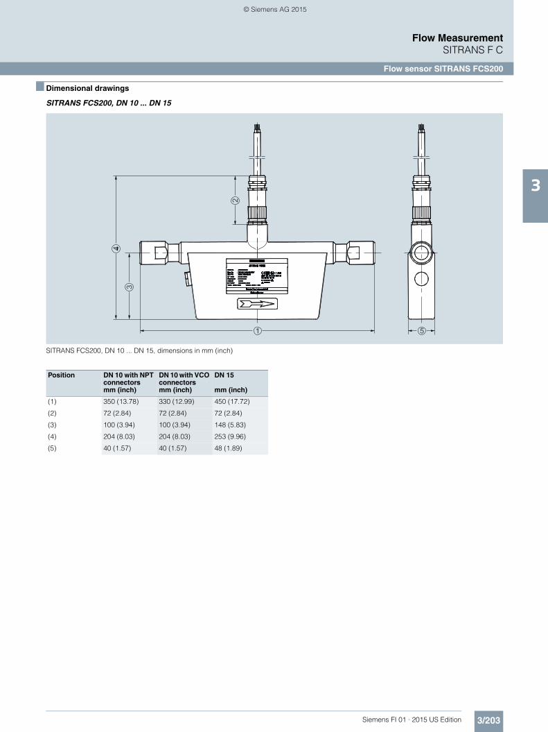
MASS 2100 DI 1.5 (1/16“)
Dimensions in mm (inch)
MASS 2100 DI 1.5 High-temperature version to 180 °C (356 °F)
Dimensions in mm (inch)
152 (5.98)
20 (0
.79)
46 (1
.81)
86 (3.39)
Ø12
9 (5
.08)
78 (3
.07)
64,5
(2.5
4)
4 (0.16)120 (4.72)
25 (0.98)Ø57 (2.4)
10 (0
.39)
100 (3.94)
G 1/4” ISO 228/1
Ø 9 (0.35)
1/4” NPTANSI/ASMEB1.20.1-1983
20 (0
.79)
G 1/4ӯ18,8 (0.74)
12 (0
.47)
15 (0
.6)
Ø24 (0.94)
NV21
1/4” NPTØ18,8 (0.74)
12 (0
.47)
15 (0
.6)
Ø24 (0.94)
NV21
192,6 (7.58)
152 (5.98)
20 (0
.79)
46 (1
.81)
86 (3.39)
Ø12
9 (5
.08)
78 (3
.07)
64,5
(2.5
4)
4 (0.16)120 (4.72)
25 (0.98)Ø57 (2.4)
10 (0
.39)
100 (3.94)
G 1/4” ISO 228/1
Ø 9 (0.35)
1/4” NPTANSI/ASMEB1.20.1-1983
20 (0
.79)
G 1/4ӯ18,8 (0.74)
12 (0
.47)
15 (0
.6)
Ø24 (0.94)
NV21
1/4” NPTØ18,8 (0.74)
12 (0
.47)
15 (0
.6)
Ø24 (0.94)
NV21
FI01_2015_us_Kap03.book Seite 208 Freitag, 20. Februar 2015 10:20 10
© Siemens AG 2015

3/209Siemens FI 01 · 2015 US Edition
Flow MeasurementSITRANS F C
Flow sensor SITRANS FC300
3
■ Overview
SITRANS FC300 is a compact Coriolis mass sensor suitable for flow measurement of a variety of liquids and gases.
The sensor offers superior performance in terms of flow accu-racy, turn-down ratio and density accuracy. The ease of installa-tion through a „plug & play“ interface ensures optimum perfor-mance and operation.
A new designed encapsulation in stainless steel with a surpris-ingly low weight of only 3.5 kg (7.7 lb), ensures a rigid and robust sensor performance for a wide range of applications.
■ Benefits
• High accuracy better than 0.1 % of mass flow rate• Large dynamic turn-down ratio better than 500:1• Densitometer performance available through a density accu-
racy as follows: - For 316L/1.4404 version better than 0.0015 g/cm3
(0.000036 lb/inch3) with repeatability better than 0.0002 g/cm3 (0.0000072 lb/inch3)
- For C22/2.4602 version better than 0.0025 g/cm3 (0.000090 lb/inch3) with repeatability better than 0.001 g/cm3 (0.000036 lb/inch3)
• One tube without internal welds, reductions or flow splitters of-fers optimal hygiene, safety and CIP cleanability for food and beverage and pharmaceutical applications
• Larger wall thickness, ensures optimal life-time and corrosion resistance and high-pressure durability
• Balanced pipe design with little mechanical energy loss, en-sures optimal performance and stability under non-ideal and unstable process conditions (pressure, temperature, density-changes etc.).
• 4-wire Pt1000 temperature measurement ensures optimum accuracy on mass flow, density and fraction flow
• Multi-plug electrical connector and SENSORPROM enable true „plug & play“. Installation and commissioning in less than 10 minutes.
• Intrinsically safe Ex design ia IIC as standard• Sensor pipe available in high-quality stainless steel
AISI 316L/1.4435 or Hastelloy C22/2.4602 offering optimum corrosion resistance.
• Rugged and space-saving sensor design in stainless steel matching all applications.
• High-pressure program as standard• The sensor calibration factor is also valid for gas measure-
ment.
■ Application
The industry today has an increasing demand for mass flowme-ters with a reduced physical size without loss of performance. The meters must be suitable for installation in traditional process industry environment as well as OEM equipment for instance within automotive or appliance industry. Independent of industry application the meter must deliver accurate and reliable meas-urements. The new and versatile design of the FC300 offers this flexibility.
■ Design
The FC300 sensor consists of a single tube bent in double omega pipe geometry, welded directly to the process connec-tors at each end. The sensor is available in 2 material configura-tions, AISI 316L/1.4404 or Hastelloy C22/2.4602 with ¼”-NPT or G¼”-ISO process connections.
The enclosure is made of stainless steel AISI 316L/1.4409 with a grade of encapsulation of IP67/NEMA 4. The enclosure has a very robust design and with an overall size of 130 x 200 x 60 mm (5.12“ x 7.87“ x 2.36“) the sensor is very com-pact and requires only little installation space.
The sensor can be delivered in a standard version with a maxi-mum liquid temperature of 115 °C (239 °F) or a high-tempera-ture version, with raised electrical connector for 180 °C (356 °F).
The sensor can be installed in horizontal or vertical position. The sensor can be mounted directly on any given plane surface or if desired with the enclosed quick release clamp fitting which, along with its compact design and multi-plug electrical connec-tor, will keep installation costs and time to a minimum.
■ Function
The measuring principle is based on the Coriolis effect. See “System information SITRANS F C Coriolis mass flowmeters”.
■ Integration
The sensor can be connected to all MASS 6000 and SIFLOW FC070 (standard and Ex types) transmitters for remote installation only.
All sensors are delivered with a SENSORPROM containing all in-formation about calibration data, identity and factory pre-pro-gramming of transmitter settings
The main applications for the SITRANS FC300 DN 4 can be found in:
Chemical industry Liquid and gas measurement in normal as well as corrosive envi-ronments
Cosmetic industry Dosing of essence and fra-grances
Pharmaceutical industry High-speed dosing and coating of pills, filling of ampuls/injectors
Food and beverage industry Filling, dosing of flavorings, colors and additives, inline density mea-surementMeasurement and dosing ofliquid or gaseous CO2
Automotive industry Fuel injection nozzle and pump testing, filling of AC units, engine consumption, paint robots, ABS test-beds
FI01_2015_us_Kap03.book Seite 209 Freitag, 20. Februar 2015 10:20 10
© Siemens AG 2015

3/210 Siemens FI 01 · 2015 US Edition
Flow MeasurementSITRANS F C
Flow sensor SITRANS FC300
3
Installation guidelines for SITRANS FC300 sensor
Horizontal installation as shown in figure A is recommended with gas or liquid applications.
This installation is also recommended when the flow velocity is low (< 1 m/s) or the liquid contains solid particles or air bubbles.
Vertical installation as shown in figure B can be used for liquid or gas applications.
For liquid applications upwards flow is recommended to facili-tate the removal of air bubbles and to avoid partly emptying of the sensor.For gas applications we recommend to place the flow inlet on the sensor high and the outlet low to remove impurities and oil films.• To ensure that the sensor does not become partly empty, there
must be a sufficient counter-pressure on the unit min. 0.2 bar (2.9 psi).
• Mount the sensor on a vibration-free and plane wall or steel frame.
• Locate the sensor low in the system in order to avoid under-pressure in the sensor separating air/gas in the liquid.
• Ensure that the sensor is not emptied of liquid (during normal operation) otherwise incorrect measurement will occur.
Horizontal mounting (recommended) (fig. A)
Liquid or gas (low to high flow)
Vertical mounting (fig. B)
Liquid or gas (medium to high flow)
■ Technical specifications
1) According to DIN 2413, DIN 174572) Housing is not rated for pressure containment.
Sensor size DN 4 (1/6“)
Mass flow
Measuring range 0 ... 350 kg/h (0 ... 772 lb/h)
Accuracy, mass flow 0.1 % of rate
Repeatability 0.05 % of rate
Max. zero point error 0.010 kg/h (0.022 lb/h)
Density
Density range 0 ... 2.9 g/cm3 (0 ... 0.105 lb/inch3)
Density error
• Stainless steel 0.007 g/cm3
(0.00025 lb/inch3)
• Hastelloy C22/2.4602 0.0025 g/cm3
(0.00009 lb/inch3)
Repeatability error 0.0002 g/cm3
(0.0000072 lb/inch3)
Temperature
Standard -40 ... +115 °C (-40 ... +239 °F)
High-temperature version -40 ... +180 °C (-40 ... +356 °F)
Temperature error 0.5 °C (0.9 °F)
Brix
Measuring range 0 ... 100 °Brix
Brix error 0.3 °Brix
Inside pipe diameter
Stainless steel version 3.5 mm (0.14“)
Hastelloy version 3.0 mm (0.12“)
Pipe wall thickness
Stainless steel version 0.25 mm (0.0098“)
Hastelloy version 0.5 mm (0.0196“)
Liquid pressure measuring pipe1)
Stainless steel 130 bar (1885 psi) at 20 °C (68 °F)
Hastelloy C22/2.4602 410 bar (5945 psi) at 20 °C (68 °F)
Materials Stainless steel AISI 316L/1.4435
Measuring pipe and connection Hastelloy C22/2.4602
Enclosure2)
Material Stainless steel AISI 316L/1.4404
Enclosure grade IP67/NEMA4
Connection thread
ISO 228/1 G¼” male
ANSI/ASME B1.20.1 ¼” NPT male
Ex approval Ex ia IIC T3-T6
05ATEX138072X
c-UL-us Class 1 Div. 1, Gr. A, B, C, D
Weight 3.5 kg (7.7 lb)
Dimensions 135 x 205 x 58 mm(5.31“ x 8.07“ x 2.28“)
FI01_2015_us_Kap03.book Seite 210 Freitag, 20. Februar 2015 10:20 10
© Siemens AG 2015

3/211Siemens FI 01 · 2015 US Edition
Flow MeasurementSITRANS F C
Flow sensor SITRANS FC300
3
Operating instructions for SITRANS F C FC300
This device is shipped with a Quick Start guide and a CD containingfurther SITRANS F literature.All literature is also available for free at: http://www.siemens.com/flowdocumentation
Accessories
Spare parts
Selection and Ordering data Article No. Order code
SITRANS F C Flow sensors 7 M E 4 4 0 0 -
SITRANS FC300 DN 4 (1/6“) sensor 77777 - 7777 777
Click on the Article No. for the online confi-guration in the PIA Life Cycle Portal.
Pipe material and temperatureStainless steel AISI 316L/1.4435115 °C (239 °F) 1 G180 °C (356 °F) 1 H
Hastelloy C22/2.4602115 °C (239 °F) 2 G180 °C (356 °F) 2 H
PressurePN 100 DPN 130 (316L/C22) GPN 410 (C22) Q
Process connectionPipe thread
G ¼“ male 1 0¼“ NPT male 1 1
ConfigurationStandard 1Density 2Brix/Plato 3Fraction (specification required) 9 N 0 Y
Transmitter compact mounted on sensor
No transmitter, sensor and adapter only A
MASS 6000, Ex d, stainless steel enclosure, 1 current, 1 freq./pulse and 1 relay output, 24 V AC/DC with Ex de [ia/ib] T3 -T6 Ex-approval
B
MASS 6000, IP67, Polyamide enclosure, cable glands M20, 1 current, 1 freq./pulse and 1 relay output, 24 V AC/DC
C
MASS 6000, IP67, Polyamide enclosure, cable glands M20, 1 current, 1 freq./pulse and 1 relay output, 115/230 V AC 50/60 Hz
D
MASS 6000, IP67, Polyamide enclosure, cable glands ½" NPT, 1 current, 1 freq./pulse and 1 relay output, 24 V AC/DC
E
MASS 6000, IP67, Polyamide enclosure, cable glands ½" NPT, 1 current, 1 freq./pulse and 1 relay output, 115/230 V AC 50/60 Hz, ½" NPT
F
CableNo cable A5 m (16.4 ft) cable B10 m (32.8 ft) cable C
25 m (82 ft) cable D
50 m (164 ft) cable E75 m (246 ft) cable F
150 m (492 ft) cable G
CalibrationStandard calibration 3 flow x 2 points 1Standard calibration matched pair 3 flow x 2 points
2
Accredited calibration matched pair 5 flow x 2 points (DANAK)
3
Extended calibration customer-specified select Y60, Y61, Y62 or Y63 (see additional information)
8
Selection and Ordering data Order code
Additional informationPlease add “-Z“ to Article No. and specify Order code(s) and plain text.
Pressure testing certificate PED: 97/23/EC C11
Material certificate EN 10204-3.1 C12
Welding certificate NDT-Penetrant: ISO 3452 C13
Factory certificate according to EN 10204 2.2 C14
Factory certificate according to EN 10204 2.1 C15
Tag name plate, stainless steel Y17
Tag name plate, plastic Y18
Customer-specific transmitter setup Y20
Customer-specified, matched pair (5 x 2) Y60
Customer-specified calibration (5 x 2) Y61
Customer-specified, matched pair (10 x 1) Y62
Customer-specified calibration (10 x 1) Y63
Cleaned for oil and grease Y80
Special version Y99
Description Article No.
• English A5E00698213
• German A5E00728101
• Spanish A5E00746629
• French A5E00746625
Description Article No.
Cable with multiple plugStandard blue cable between MASS 6000 and MASS 2100, 5 x 2 x 0.34 mm2 twisted and screened in pairs. Temperature range -20 °C ... +110 °C (-4 °F ... +230 °F)
• 5 m (16.4 ft) FDK:083H3015
• 10 m (32.8 ft) FDK:083H3016
• 25 m (82 ft) FDK:083H3017
• 50 m (164 ft) FDK:083H3018
• 75 m (246 ft) FDK:083H3054
• 150 m (492 ft) FDK:083H3055
Description Article No.
Multiple plug for cable mounting
FDK:083H5056
2 kB SENSORPROM unit(Sensor Serial No. and Article No. must be specified by ordering)
FDK:083H4410
Mounting bracket in AISI 304 A5E02590439
Demo suitcaseincluding MASS 6000, FC300 (DN 4),and HART module
A5E00789737
FI01_2015_us_Kap03.book Seite 211 Freitag, 20. Februar 2015 10:20 10
© Siemens AG 2015

3/212 Siemens FI 01 · 2015 US Edition
Flow MeasurementSITRANS F C
Flow sensor SITRANS FC300
3
■ Characteristic curves
Pressure drop
Stainless steel 316L/1.4404
Hastelloy C22/2.4602
Viscosity [cSt]
Mass flow [kg/h]
0.1
1.0
500103
10Δp [bar]
1
5
10
20501002005001000
100
2
10
103
1.0
0.1100 300 [kg/h]
P [bar]
FI01_2015_us_Kap03.book Seite 212 Freitag, 20. Februar 2015 10:20 10
© Siemens AG 2015

3/213Siemens FI 01 · 2015 US Edition
Flow MeasurementSITRANS F C
Flow sensor SITRANS FC300
3
■ Dimensional drawings
SITRANS FC300 DN 4
SITRANS FC300, dimensions in mm (inch)
NV 24 (0.95)
12 (0.47)15 (0.59)
Ø18
,8 (0
.74) 1/
4”-1
8 N
PT
12 (0.47)15 (0.59)
G 1
/4”
Ø18
,8 (0
.740
)
18,8
(0.7
4)
NV 5 (0.20)
77 (3
.03)
121
(4.7
6)
58 (2.28)
M4
135 (5.31)
75 (2.95)
32 (1
.26)
Ø27
(1.0
6)
190 (3.54)
19 (0
.75)
NV 6 (0.24)
2 x M8
28,8
(1.1
34)
14 ±
2 (0
.55
± 0.
08)
38 (1
.50)
110 (4.33)M8
1/4”-18 NPT (ANSI/ASME B1.20.1)
G 1/4” (ISO 228/1 )
205
(8.0
7)
20 (1
.33)
FI01_2015_us_Kap03.book Seite 213 Freitag, 20. Februar 2015 10:20 10
© Siemens AG 2015

3/214 Siemens FI 01 · 2015 US Edition
Flow MeasurementSITRANS F C
Flow sensor MASS 2100 DI 3 to DI 15
3
■ Overview
MASS 2100 DI 3 to DI 15 is suitable for accurate mass flow measurement of a variety of liquids and gases.
The sensor offers superior performance in terms of flow accu-racy, turn-down ratio and density accuracy. The ease of installa-tion through a "plug & play" mechanical and electrical interface ensures optimum performance and operation.
The sensor delivers true multi-parameter measurements i.e.: Mass flow, volume flow, density, temperature and fraction.
■ Benefits
• High accuracy better than 0.1 % of mass flow rate • Large dynamic turn-down ratio better than 500:1• Densitometer performance available through density accu-
racy (depending upon sensor size) ranging from 0.0005 to 0.0015 g/cm3 with a typical repeatability better than 0.0001 to 0.0002 g/cm3
• Single continuous tube design, with no internal welds, reduc-tions or flow splitters offers optimal hygiene, safety and CIP cleanability for food and beverage and pharmaceutical appli-cations
• Markets’ thickest sensor walls ensure optimal life-time and corrosion resistance and high-pressure durability
• Full bore design provides lower pressure loss due to same in-ternal diameter throughout the entire sensor
• Balanced pipe design with little mechanical energy loss, en-sures optimal performance and stability under non-ideal and unstable process conditions (pressure, temperature, density changes etc.)
• 4-wire Pt1000 temperature measurement ensures optimum accuracy on mass flow, density and fraction flow
• Multi-plug electrical connector and SENSORPROM enables true "plug & play". Installation and commissioning in less than 10 minutes
• Intrinsically safe Ex design ia IIC as standard, making service in hazardous area possible without having to demount the sensor if a compact Ex d transmitter needs service
• Sensor pipe available in high-quality stainless steel AISI 316L/1.4435 or Hastelloy C22/2.4602 offering optimum corrosion resistance
• Centre-block design decouples process noise from the envi-ronment such as vibrations, pulsations, pressure shocks etc. making installation flexible and versatile
• Rugged and space-saving sensor design in stainless steel matching all environments
• High-pressure program as standard• The sensor calibration factor is also valid for gas measure-
ment• Uniform sensor interface matching all transmitter versions at
the same time whether it is compact IP67/NEMA 6, compact Ex d or remote installation, one sensor fits all
■ Application
Coriolis mass flowmeters are suitable for measuring all liquids and gases. The measurement is independent of changes in pro-cess conditions/parameters such as temperature, density, pres-sure, viscosity, conductivity and flow profile.
Due to this versatility the meter is easy to install and the Coriolis flowmeter is recognized for its high accuracy in a wide turn-down ratio which is a paramount in many applications.
The wide varity of combinations and versions from the modular system means that ideal adaptation is possible to each measur-ing task.
■ Design
The MASS 2100 sensor consists of a single bent tube in a double bent pipe configuration, welded directly to the process connec-tors at each end.The centre-block is brazed onto the sensor pipes from the out-side acting as a mechanical low pass filter.
The sensor is available in 2 material configurations, AISI 316L/1.4404 or Hastelloy C22/2.4602 with a wide variety of process connections.
The enclosure is made in stainless steel AISI 316L/1.4404 with a grade of encapsulation of IP67.
The sensor is as standard Ex ia approved, intrinsically safe.
The sensor can be installed in horizontal or vertical position. In horizontal position the sensor is self draining.
Heating: All the sensors MASS 2100, DI 3 to DI 15, can option-ally be equipped with a heating coil to avoid solidification of sen-sitive fluids during down-time or period between discontinuing processes. This feature gives the user an alternative to the costly electrical heating normally used, as it gives the freedom to choose either hot water, superheated steam or hot oil, to main-tain a constant temperature inside the sensor.
The main applications of the Coriolis flowmeter can be found in all industries, such as:
Chemical and pharma Detergents, bulk chemicals,pharmaceuticals, acids, alkalis
Food and beverage Dairy products, beer, wine,soft-drinks, Brix/Plato, fruit juices and pulps, bottling, CO2 dosing, CIP-liquids
Automotive Fuel injection nozzle and pump testing, filling of AC units, engine consumption, paint robots
Oil and gas Filling of gas bottles, furnace con-trol, test separators, LPG
Water and waste water Dosing of chemicals for water treatment
FI01_2015_us_Kap03.book Seite 214 Freitag, 20. Februar 2015 10:20 10
© Siemens AG 2015

3/215Siemens FI 01 · 2015 US Edition
Flow MeasurementSITRANS F C
Flow sensor MASS 2100 DI 3 to DI 15
3
■ Function
The measuring principle is based on the Coriolis effect. See “System information SITRANS F C Coriolis mass flowmeters”.
■ Integration
The sensor can be connected to all MASS 6000 transmitters for compact and remote installation as well as SIFLOW FC070 stan-dard and Ex type transmitters.
All sensors are delivered with a SENSORPROM containing all in-formation about calibration data, identity and factory pre-pro-gramming of transmitter settings.
Installation guidelines MASS 2100 DI 3 ... DI 15 (1/8" ... ½")
Installation of sensor
In order to perform according to given specifications for flow and density accuracy, the sensor must be installed using rigid mounting brackets as shown in the installation examples.
If the liquid is volatile or contains solid particles, vertical mount-ing is not recommended.
Vibration
Always locate the flowmeter as far away as possible from com-ponents that generate mechanical vibration in the piping.
Cross talk
Cross talk between sensors mounted close to each other may disturb the measurement. To avoid cross talk never mount more than one meter on each frame and mount flexible hose connec-tions between the sensors as shown.
Zero point adjustment
To facilitiate zero point adjustment a shut-off valve should always be mounted in connection with the sensor as a proper zero point setting is essential for a good accuarcy.
Liquid Gas
Horizontal
Vertical
FI01_2015_us_Kap03.book Seite 215 Freitag, 20. Februar 2015 10:20 10
© Siemens AG 2015

3/216 Siemens FI 01 · 2015 US Edition
Flow MeasurementSITRANS F C
Flow sensor MASS 2100 DI 3 to DI 15
3
■ Technical specifications
1) Max. at 20 °C (68 °F), DIN 2413, DIN 174572) Other connections to order, see “Selection and Ordering data”3) Material, AISI 316/1.4401 or corresponding
For accuracy specification see “System information SITRANS F C”.
Versions (mm (inch)) DI 3 (1/8) DI 6 (¼) DI 15 (5/8) DI 25 (1) DI 40 (1½)
Inside pipe diameter (sen-sor consists of one continu-ous pipe)
mm (inch) 3.0 (0.12) 6.0 (0.24) 14.0 (0.55) 29.7 (1.17) 43.1 (1.70)
Pipe wall thickness mm (inch) 0.5 (0.02) 1.0 (0.04) 1.0 (0.04) 2.0 (0.08) 2.6 (0.10)
Mass flow measuring range
kg/h (lb/h) 0 ... 250 (0 ... 550) 0 ... 1000 (0 ... 2200)
0 ... 5600 (0 ... 12345)
0 ... 25000 (0 ... 55100)
0 ... 52000 (0 ... 114600)
Density g/cm3
(lb/inch3)0 ... 2.9 (0 ... 0.10)
Fraction e.g. °Brix 0 ... 70 (applicable temperature range: 10 ... 99 °C (50 ... 210.2 °F))
Temperature
Standard °C (°F) -50 ... +180 °C (-58 ... +356 °F)
Liquid pressure measur-ing pipe1)
Stainless steel bar (psi) 230 (3336) 265 (3844) 130 (1885) 110 (1595) 105 (1523)
Hastelloy C22/2.4602 bar (psi) 350 (5076) 410 (5946) 200 (2900) 185 (2683) not available
Materials
Measuring pipe, flange and thread connection
Stainless steel AISI 316L/1.4435
Hastelloy C22/2.4602 not available
Enclosure and enclosure material
IP67 (NEMA 4) and stainless steel AISI 316L/1.4404,The housing is not rated for pressure containment
Process connections2)
Flange
EN 1092-1, PN 40 DN 10 DN 15 DN 25 DN 40
ANSI B16.5, Class 150 ½” ½” 1” 1½”
ANSI B16.5, Class 600 (Class 300)
½” ½” 1” 1½”
Dairy screwed connec-tion (PN 16/25/40)3)
DIN 11851 DN 10 DN 15 DN 32 DN 40
ISO 2853/BS 4825 part 4 (SS3351)
25 mm 25 mm 38 mm 51 mm
Dairy clamp connection (PN 16)3)
ISO 2852/BS 4825 part 3 (SMS3016)
25 mm 25 mm 38 mm 51 mm
Thread
ISO 228/1, PN 100 G¼” female G¼” male G½” male G1“ male G2“ male
ANSI/ASME B1.20.1, PN 100
¼” NPT female ¼” NPT male ½” NPT male 1“ NPT male 2“ NPT male
Cable connection Multiple plug connection to sensor 5 x 2 x 0.35 mm2 twisted and screened in pairs, ext. Ø 12 mm
Ex-version Ex ia IIC T3-T6, DEMKO 03 ATEX 135252X
Weight approx. kg (lb) 4 (8.8) 8 (17.6) 12 (26.5) 48 (105.8) 70 (154.5)
FI01_2015_us_Kap03.book Seite 216 Freitag, 20. Februar 2015 10:20 10
© Siemens AG 2015

3/217Siemens FI 01 · 2015 US Edition
Flow MeasurementSITRANS F C
Flow sensor MASS 2100 DI 3 to DI 15
3
Pressure drop
MASS 2100 DI 3 (1/8”), pressure drop for density = 1000 kg/m3
MASS 2100 DI 6 (¼“), pressure drop for density = 1000 kg/m3
MASS 2100 DI 15 (½”), pressure drop for density = 1000 kg/m3
MASS 2100 DI 25 (1”), pressure drop for density = 1000 kg/m3
Viscosity [cSt]
Mass flow [kg/h]
0.1
1.0
Δp [bar]
300100103
101000 2050200 100500
10
5
2
1
Viscosity [cSt]
Mass flow [kg/h]
0.1
1.0
1
20
50
Δp [bar]
10
100010010
1002005001000
Viscosity [cSt]
Mass flow [kg/h]
0.1
1.0
p [ bar]
10
60 100 1000 6000
100
50
00
1
20
10
D0 0
52
0
0
Viscosity [cSt]
Mass flow [kg/h]
0.1
1.0
100
200
120
50
500
1000
30000100001000300
10Δp [bar]
FI01_2015_us_Kap03.book Seite 217 Freitag, 20. Februar 2015 10:20 10
© Siemens AG 2015

3/218 Siemens FI 01 · 2015 US Edition
Flow MeasurementSITRANS F C
Flow sensor MASS 2100 DI 3 to DI 15
3
MASS 2100 DI 40 (1½”), pressure drop for density = 1000 kg/m3
Pressure/temperature curves
ASME flanges B16.5 stainless steel
ASME flanges B16.5 Hastelloy C22/2.4602
DIN 32676 flanges stainless steel (PN 10 ... PN 25)
DIN 11581 flanges stainless steel (PN 25 ... PN 40)
Viscosity [cSt]
Mass flow [kg/h]
0.1
1.0100
200
1
2050
1000
500
50000100001000500
10Δp [bar]
CLASS150
CLASS300
CLASS600
Pro
cess
Pre
ssur
e (b
ar)
ANSI Flange Ratings per ASME B16.5, Material Group 2.3
Process temperature (°C)1801308030-20 0
90
70
60
50
30
20
10
60
30
12
110
100
40
80
CLASS150
CLASS300
CLASS600
Pro
cess
Pre
ssur
e (b
ar)
ANSI Flange Ratings per ASME B16.5, Group Material 3.8
Process temperature (°C)1801308030-20 0
90
80
70
60
50
40
30
20
10
98
49
15
110
100
Pro
cess
pre
ssur
e (b
ar)
Process temperature (°C)1801201008020 40-20 0
45
40
35
30
25
20
15
10
5
60 140 160
PN25
PN16
PN10
DIN 32676
25
10
16
Pro
cess
Pre
ssur
e (b
ar)
Process temperature (°C)1801201008020 40-20 0
45
40
35
30
25
20
15
10
5
60 140 160
DIN 11851
PN25 DN50 - DN100
PN16 DN125 - DN150
PN40 DN10 - DN40
25
40
16
FI01_2015_us_Kap03.book Seite 218 Freitag, 20. Februar 2015 10:20 10
© Siemens AG 2015

3/219Siemens FI 01 · 2015 US Edition
Flow MeasurementSITRANS F C
Flow sensor MASS 2100 DI 3 to DI 15
3
EN 1092 flanges stainless steel (PN 40 ... PN 100)
EN 1092 flanges Hastelloy C22/2.4602 (PN 40 ... PN 100)
ISO 228 and NPT pipe thread stainless steel (PN 100 ... PN 265)
ISO 218 and NPT pipe thread stainless steel (PN 185 ... PN 410)
For further information on the PED standard and requirements, see page 9/6.
Pro
cess
pre
ssur
e (b
ar)
Metric flange ratings, EN 1092-1, Material group 13E0
Process temperature (°C)1801308030-20 0
90
80
70
60
50
40
30
20
10
82
52
33
110
100
PN40
PN63
PN100
Pro
cess
Pre
ssur
e (b
ar)
Flange EN 1092-1, UNS NO6022
Process temperature (°C)1801308030-20 0
90
80
70
60
50
40
30
20
10
79
50
31
110
100
PN40
PN63
PN100
Pro
cess
Pre
ssur
e (b
ar)
ISO 228, Pipe thread NPT - ANSI/ASME B1.20.1, Pipe thread
Process temperature (°C)1801308030-20 0
60
188
164
92
360
310
110
160
210
260
PN130
PN230
PN265
71
PN100
Pro
cess
Pre
ssur
e (b
ar)
ISO 228, Pipe thread NPT - ANSI/ASME B1.20.1, Pipe thread UNS NO6022
Process temperature (°C)1801308030-20 0
120
322
287275
157
420
370
170
220
270
320
PN200
PN350PN365
PN410
PN185
145
FI01_2015_us_Kap03.book Seite 219 Freitag, 20. Februar 2015 10:20 10
© Siemens AG 2015

3/220 Siemens FI 01 · 2015 US Edition
Flow MeasurementSITRANS F C
Flow sensor MASS 2100 DI 3 to DI 15
3
Selection and Ordering data Article No. Ord. code
SITRANS F C sensors
MASS 2100 without heating jacket 7 ME 4 1 0 0 -
MASS 2100 heated, DN 15 connection 7 ME 4 2 0 0 -
MASS 2100 heated, ½ inch, ANSI B16.5 connection
7 ME 4 2 1 0 -
77777 - 7777 777
Click on the Article No. for the online confi-guration in the PIA Life Cycle Portal.
Diameter
Stainless steel AISI 316L/1.4435DI 3 (PN 100/PN 230) 1 C
DI 6 1 DDI 15 1 E
Hastelloy C22/2.4602DI 3 (PN 100/PN 350) 2 CDI 6 2 D
Pressure
PN 16 (DI 6, DI 15) APN 25 (DI 6, DI 15) BPN 40 (DI 6, DI 15) C
PN 100 (DI 3, DI 6, DI 15) DPN 130 (DI 15, ½“, AISI 316L/1.4404) G
PN 200 (DI 15, ½“, Hastelloy C22/2.4602) KPN 230 (DI 3, ¼“, AISI 316L/1.4404) LPN 265 (DI 6, ¼“, AISI 316L/1.4404) M
PN 350 (DI 3, ¼“, Hastelloy C22/2.4602) NPN 410 (DI 6, ¼“, Hastelloy C22/2.4602) Q
Class 150 (DI 6, DI 15) RClass 600 (DI 6, DI 15) S
Process connection/flange
Pipe thread
G ¼“ 1 0¼“ NPT 1 1G ½“ 1 2
½“ NPT 1 3G 1 1 41“ NPT 1 5
G 2“ 1 62“ NPT 1 7
Flange EN1092-1 Form B
DN 10 (PN 40/PN 100) 2 0DN 15 (PN 40/PN 100) 2 1DN 25 (PN 40/PN 100) 2 2
DN 40 (PN 40/PN 100) 2 3DN 50 (PN 40/PN 100) 2 4
Flange ASME/ANSI B 16.5
½“ (class 150/class 600) 3 0¾“ (class 150/class 600) 3 11“ (class 150/class 600) 3 2
1 ½“ (class 150/class 600) 3 32“ (class 150/class 600) 3 4
Dairy screwed connection DIN 11851
DN 10 (PN 40) 4 0DN 15 (PN 40) 4 1DN 25 (PN 40) 4 2
DN 32 (PN 40) 4 3DN 40 (PN 25) 4 4DN 50 (PN 25) 4 5
DN 65 (PN 25) 4 6
Dairy clamp connection ISO 2852 (DIN 32676)Cone down the sensor in order to obtain self- drainage with connectors ISO 2852
25 mm (PN 16) 5 038 mm (PN 16) 5 151 mm (PN 16) 5 2
Dairy screwed connection ISO 2853
25 mm (PN 16) 6 038 mm (PN 16) 6 151 mm (PN 16) 6 2
Configuration/calibration type
Standard 1Density 2Brix/Plato 3
Fraction (specification required) 9 N 0 Y
Transmitter compact mounted on sensor
No transmitter, sensor and adapter only A
MASS 6000, Ex d, stainless steel enclosure, 1 current, 1 freq./pulse and 1 relay output, 24 V AC/DC with Ex de [ia/ib] T3 -T6 Ex-approval
B
MASS 6000, IP67, Polyamide enclosure, cable glands M20, 1 current, 1 freq./pulse and 1 relay output, 24 V AC/DC
C
MASS 6000, IP67, Polyamide enclosure, cable glands M20, 1 current, 1 freq./pulse and 1 relay output, 115/230 V AC 50/60 Hz
D
MASS 6000, IP67, Polyamide enclosure, cable glands ½" NPT, 1 current, 1 freq./pulse and 1 relay output, 24 V AC/DC
E
MASS 6000, IP67, Polyamide enclosure, cable glands ½" NPT, 1 current, 1 freq./pulse and 1 relay output, 115/230 V AC 50/60 Hz
F
CableNo cable A5 m (16.4 ft) cable B10 m (32.8 ft) cable C
25 m (82 ft) cable D50 m (164 ft) cable E75 m (246 ft) cable F
150 m (492 ft) cable G
Calibration/verification
Standard calibration 3 flow x 2 points 1Stand. calibration matched pair 3 flow x 2 points 2Accredited calibration matched pair 5 flow x 2 points (DANAK to ISO 17025)
3
Extended calibration customer-specified select Y60, Y61, Y62 or Y63 (see additional information)
8
Selection and Ordering data Article No. Ord. code
SITRANS F C sensors
MASS 2100 without heating jacket 7 ME 4 1 0 0 -
MASS 2100 heated, DN 15 connection 7 ME 4 2 0 0 -
MASS 2100 heated, ½ inch, ANSI B16.5 connection
7 ME 4 2 1 0 -
77777 - 7777 777
FI01_2015_us_Kap03.book Seite 220 Freitag, 20. Februar 2015 10:20 10
© Siemens AG 2015

3/221Siemens FI 01 · 2015 US Edition
Flow MeasurementSITRANS F C
Flow sensor MASS 2100 DI 3 to DI 15
3
Operating instructions forSITRANS F C MASS 2100 DI 3 to DI 40
This device is shipped with a Quick Start guide and a CD containingfurther SITRANS F literature.
All literature is also available for free at: http://www.siemens.com/flowdocumentation
■ Selection and Ordering data
Accessories
Spare parts
Dairy MLFB example
MASS 2100 7 M E 4 1 0 0 - 77777 7777
Sensor size DI 15, AISI 316L/1.4435
1 E
PN 40 C
DN 15 connector 4 1
Standard configuration/calibration 1
MASS 6000 IP67 compact mounted D
No cable A
Standard calibration, 3 flow x 2 points 1
Selection and Ordering data Order code
Addtional informationPlease add “-Z“ to Article No. and specify Order code(s) and plain text.
Pressure testing certificate PED: 97/23/EC C11
Material certificate EN 10204-3.1 C12
NDT- X-ray inspection report: EN 1435DI3 sensor only: NDT-Penetrant inspection report ISO 3452.
C13
Factory certificate according to EN 10204 2.2 C14
Factory certificate according to EN 10204 2.1 C15
Tag name plate, stainless steel Y17
Tag name plate, plastic Y18
Customer-specific transmitter setup Y20
Customer-specified, matched pair (5 x 2) Y60
Customer-specified calibration (5 x 2) Y61
Customer-specified, matched pair (10 x 1) Y62
Customer-specified calibration (10 x 1) Y63
Cleaned for oil and grease Y80
Special version Y99
Description Article No.
• English A5E02896535
• German A5E03073519
• Spanish A5E03073549
• French A5E03073539
Description Dimension Article No.
Mating parts for hygienic fittings DIN 11851Includes:• 2 unions• 2 mating parts (for welding in)• 2 EPDM gaskets
DN 10 FDK:085U1016
DN 15 FDK:085U1017
DN 25 FDK:085U1019
DN 32 FDK:085U1020
DN 40 FDK:085U1021
DN 50 FDK:085U1022
DN 65 FDK:085U1023
Mating parts for hygienic clamp ISO 2852Includes:• 2 clamps• 2 mating parts• 2 EPDM gaskets
25 mm FDK:085U1029
40 mm FDK:085U1031
50 mm FDK:085U1032
2 EPDM gaskets with collar for mounting set DIN 11851
DN 10 FDK:085U1006
DN 15 FDK:085U1007
DN 25 FDK:085U1009
DN 32 FDK:085U1010
DN 40 FDK:085U1011
DN 50 FDK:085U1012
DN 65 FDK:085U1013
Description Length Article No.
Cable with multiple plugStandard blue cable between MASS 6000 and MASS 2100, 5 x 2 x 0.34 mm2 twisted and screened in pairs. Temperature range -20 °C ... +110 °C (-4 °F ... +230 °F)
5 m (16.4 ft) FDK:083H3015
10 m (32.8 ft) FDK:083H3016
25 m (82 ft) FDK:083H3017
50 m (164 ft) FDK:083H3018
75 m (246 ft) FDK:083H3054
150 m (492 ft) FDK:083H3055
Description Article No.
Adapter for MASS 2100 FDK:083L8889
Multiple plug for cable mounting FDK:083H5056
2 kB SENSORPROM unit, including programming(Sensor Serial No. and Article No. must be specified by ordering)
FDK:083H4410
FI01_2015_us_Kap03.book Seite 221 Freitag, 20. Februar 2015 10:20 10
© Siemens AG 2015

3/222 Siemens FI 01 · 2015 US Edition
Flow MeasurementSITRANS F C
Flow sensor MASS 2100 DI 3 to DI 15
3
■ Dimensional drawings
MASS 2100 sensor
Dimension in mm (inch)For not listed variants please contact product support
Flange EN 1092-1ANSI B16.5
Clamp ISO 2852
Screwed connector for Di 3 ISO 228/1-G 1/4 and ANSI/ASME B1.20.1-1983 1/4 NPT
Dairy screwed connection DIN 11851 (Connection)
17.5 (0.69)
88 (3.5)
225
(8.8
6)
284
(11.
2)
155 (6.10)
130 (5.12)
77 (3
.03)
L1
L2
L1
L1
L1
L1
D2
H1
L2
D1
D5
D4
D3
B1
Sensor size
Connections L1mm
L2mm
L3mm
H1mm
B1mm
D1mm
D2mm
D3mm
D4mm
D5mm
DI (inch) Type Pressure rating Size
DI 3(1/8)
Pipe thread ISO 228/1 - G¼ PN 100 ¼” 400 280 75.5 60 0 21.3 104 - - -Pipe thread ANSI/ASME B 1.20.1 - ¼” NPT
PN 100 ¼” 400 280 75.5 60 0 21.3 104 - - -
DI 6(¼)
Flange EN 1092-1 PN 100 DN 10 580 390 62.0 40 12 17.0 104 100 70.0 14.0Flange EN 1092-1 PN 40 DN 10 560 390 62.0 40 12 17.0 104 90.0 60.0 14.0Flange ANSI B16.5 Class 150 ½“ 624 390 62.0 40 12 17.0 104 88.9 60.5 15.7Flange ANSI B16.5 Class 600 ½“ 608 390 62.0 40 12 17.0 104 95.3 66.5 15.7Screwed connection DIN 11851 PN 40 DN 10 532 390 62.0 40 12 17.0 104 - - -Clamp ISO 2852 PN 16 25 mm 570 390 62.0 40 12 17.0 104 - - -
DI 15(½)
Flange EN 1092-1 PN 100 DN 15 634 444 75.5 44 20 21.3 129 105 75.0 14.0Flange EN 1092-1 PN 40 DN 15 620 444 75.5 44 20 21.3 129 95.0 65.0 14.0Flange ANSI B16.5 Class 150 ½“ 639 444 75.5 44 20 21.3 129 88.9 60.5 15.7Flange ANSI B16.5 Class 600 ½“ 660 444 75.5 44 20 21.3 129 95.3 66.5 15.7Screwed connection DIN 11851 PN 40 DN 15 586 444 75.5 44 20 21.3 129 - - -Clamp ISO 2852 PN 16 25 mm 624 444 75.5 44 20 21.3 129 - - -
DI 25(1)
Flange EN 1092-1 PN 100 DN 25 970 700 75.5 126 25 33.7 219 140.0 100.0 18.0Flange EN 1092-1 PN 40 DN 25 934 700 75.5 126 25 33.7 219 115.0 85.0 14.0Flange ANSI B16.5 Class 150 1“ 967 700 75.5 126 25 33.7 219 108.0 79.2 15.7Flange ANSI B16.5 Class 600 1“ 992 700 75.5 126 25 33.7 219 124.0 88.9 19.1Screwed connection DIN 11851 PN 40 DN 32 922 700 75.5 126 25 33.7 219 - - -Clamp ISO 2852 PN 16 38 mm 940 700 75.5 126 25 33.7 219 - - -
DI 40(1½)
Flange EN 1092-1 PN 100 DN 40 1100 850 75.5 180 0 48.3 273 170.0 125.0 22.0Flange EN 1092-1 PN 40 DN 40 1063 850 75.5 180 0 48.3 273 150.0 110.0 18.0Flange ANSI B16.5 Class 150 1½“ 1100 850 75.5 180 0 48.3 273 127.0 98.6 15.7Flange ANSI B16.5 Class 600 1½“ 1128 850 75.5 180 0 48.3 273 155.4 114.3 22.4Screwed connection DIN 11851 PN 25 DN 50 1090 850 75.5 180 0 48.3 273 - - -Clamp ISO 2852 PN 25 51 mm 1062 850 75.5 180 0 48.3 273 - - -
FI01_2015_us_Kap03.book Seite 222 Freitag, 20. Februar 2015 10:20 10
© Siemens AG 2015

3/223Siemens FI 01 · 2015 US Edition
Flow MeasurementSITRANS F C
Flow sensor MASS 2100 DI 3 to DI 15
3
For not listed variants please contact product support.
Sensor size
Connections L1inch
L2inch
L3inch
H1inch
B1inch
D1inch
D2inch
D3inch
D4inch
D5inch
DI (inch) Type Pressure rating Size
DI 3(1/8)
Pipe thread ISO 228/1 - G¼ PN 100 ¼” 15.75 11.02 2.97 2.36 0 0.84 4.09 - - -
Pipe thread ANSI/ASME B 1.20.1 - ¼” NPT
PN 100 ¼” 15.75 11.02 2.97 2.36 0 0.84 4.09 - - -
DI 6(¼)
Flange EN 1092-1 PN 100 DN 10 22.83 15.35 2.44 1.57 0.47 0.67 4.09 3.94 2.76 0.55
Flange EN 1092-1 PN 40 DN 10 22.05 15.35 2.44 1.57 0.47 0.67 4.09 3.54 2.36 0.55
Flange ANSI B16.5 Class 150 ½“ 24.57 15.35 2.44 1.57 0.47 0.67 4.09 3.5 2.38 0.62
Flange ANSI B16.5 Class 600 ½“ 23.94 15.35 2.44 1.57 0.47 0.67 4.09 3.75 2.62 0.62
Screwed connection DIN 11851 PN 40 DN 10 20.94 15.35 2.44 1.57 0.47 0.67 4.09 - - -
Clamp ISO 2852 PN 16 25 mm 22.44 15.35 2.44 1.57 0.47 0.67 4.09 - - -
DI 15(½)
Flange EN 1092-1 PN 100 DN 15 24.96 17.48 2.97 1.73 0.79 0.84 5.08 2.95 4.13 0.55
Flange EN 1092-1 PN 40 DN 15 24.41 17.48 2.97 1.73 0.79 0.84 5.08 3.74 2.56 0.55
Flange ANSI B16.5 Class 150 ½“ 25.16 17.48 2.97 1.73 0.79 0.84 5.08 3.5 2.38 0.62
Flange ANSI B16.5 Class 600 ½“ 25.98 17.48 2.97 1.73 0.79 0.84 5.08 3.75 2.62 0.62
Screwed connection DIN 11851 PN 40 DN 15 23.07 17.48 2.97 1.73 0.79 0.84 5.08 - - -
Clamp ISO 2852 PN 16 25 mm 24.57 17.48 2.97 1.73 0.79 0.84 5.08 - - -
DI 25(1)
Flange EN 1092-1 PN 100 DN 25 38.19 27.56 2.97 4.96 0.98 1.33 8.62 3.94 5.51 0.71
Flange EN 1092-1 PN 40 DN 25 36.77 27.56 2.97 4.96 0.98 1.33 8.62 4.53 3.35 0.55
Flange ANSI B16.5 Class 150 1“ 38.07 27.56 2.97 4.96 0.98 1.33 8.62 4.25 3.12 0.62
Flange ANSI B16.5 Class 600 1“ 39.06 27.56 2.97 4.96 0.98 1.33 8.62 4.88 3.50 0.75
Screwed connection DIN 11851 PN 40 DN 32 36.30 27.56 2.97 4.96 0.98 1.33 8.62 - - -
Clamp ISO 2852 PN 16 38 mm 37.01 27.56 2.97 4.96 0.98 1.33 8.62 - - -
DI 40(1½)
Flange EN 1092-1 PN 100 DN 40 43.31 33.46 2.97 7.09 0 1.9 10.75 4.92 6.69 0.87
Flange EN 1092-1 PN 40 DN 40 41.85 33.46 2.97 7.09 0 1.9 10.75 5.91 4.33 0.71
Flange ANSI B16.5 Class 150 1½“ 43.31 33.46 2.97 7.09 0 1.9 10.75 5 3.88 0.62
Flange ANSI B16.5 Class 600 1½“ 44.41 33.46 2.97 7.09 0 1.9 10.75 6.12 4.50 0.88
Screwed connection DIN 11851 PN 25 DN 50 42.91 33.46 2.97 7.09 0 1.9 10.75 - - -
Clamp ISO 2852 PN 25 51 mm 41.81 33.46 2.97 7.09 0 1.9 10.75 - - -
FI01_2015_us_Kap03.book Seite 223 Freitag, 20. Februar 2015 10:20 10
© Siemens AG 2015

3/224 Siemens FI 01 · 2015 US Edition
Flow MeasurementSITRANS F C
Flow sensor MASS 2100 DI 3 to DI 15
3
MASS 2100 sensor with “heating jacket”
Dimensions in mm (inch)
MASS 2100 and MASS 6000 Ex d compact version
Dimensions in mm (inch)
MASS 2100 and MASS 6000 IP67 compact version
Dimensions in mm (inch)
D6
D7
L5
D8
H3
H3
B2
Sensor size Connec-tions heated
L5 H3 B2 D6 D7 D8
DI (inch) Type Pressure rating Size mm (inch) mm (inch) mm (inch) mm (inch) mm (inch) mm (inch)
DI 3 (1/8) EN 1092-1 PN 40 DN 15 234 (9.21) 122 (4.8) 22 (0.87) 95 (3.74) 65.0 (2.56) 14.0 (0.55)
ANSI B16.5 Class 150 ½" 234 (9.21) 131.6 (5.18) 22 (0.87) 88.9 (3.5) 60.5 (2.38) 15.7 (0.62)
DI 6 (¼) EN 1092-1 PN 40 DN 15 234 (9.21) 112 (4.41) 22.7 (0.89) 95 (3.74) 65.0 (2.56) 14.0 (0.55)
ANSI B16.5 Class 150 ½" 234 (9.21) 121.6 (4.79) 22.7 (0.89) 88.9 (3.5) 60.5 (2.38) 15.7 (0.62)
DI 15 (½) EN 1092-1 PN 40 DN 15 234 (9.21) 126.5 (4.98) 31.5 (1.24) 95 (3.74) 65.0 (2.56) 14.0 (0.55)
ANSI B16.5 Class150 ½" 234 (9.21) 136.1 (5.36) 31.5 (1.24) 88.9 (3.5) 60.5 (2.38) 15.7 (0.62)
DI 25 (1) EN 1092-1 PN 40 DN 15 420 (16.54) 213.6 (8.41) 60 (2.36) 95 (3.74) 65.0 (2.56) 14.0 (0.55)
ANSI B16.5 Class 150 ½" 420 (16.54) 223.2 (8.79) 60 (2.36) 88.9 (3.5) 60.5 (2.38) 15.7 (0.62)
DI 40 (1½) EN 1092-1 PN 40 DN 15 500 (19.68) 267.5 (10.53) 43 (1.69) 95 (3.74) 65.0 (2.56) 14.0 (0.55)
ANSI B16.5 Class 150 ½" 500 (19.68) 277.1 (10.91) 43 (1.69) 88.9 (3.5) 60.5 (2.38) 15.7 (0.62)
Sensor size [DI (inch)]
L3[mm (inch)]
H5[mm (inch)]
H6[mm (inch)]
H5 + H6[mm (inch)]
3 (1/8) 75 (2.95) 82 (3.23) 247 (9.72) 329 (12.95)
6 (¼) 62 (2.44) 72 (2.83) 257 (10.12) 329 (12.95)
15 (½) 75 (2.95) 87 (3.43) 267 (10.51) 354 (13.94)
25 (1) 75 (2.95) 173 (6.81) 271 (10.67) 444 (17.48)
40 (1½) 75 (2.95) 227 (8.94) 271 (10.67) 498 (19.61)
255.1 (10.04)Ø130 (5.12)
H5
H6
L3
Sensor size [DI (inch)]
L3[mm (inch)]
H5[mm (inch)]
H6[mm (inch)]
H5 + H6[mm (inch)]
3 (1/8) 75 (2.95) 82 (3.23) 306 (12.04) 388 (15.28)
6 (¼) 62 (2.44) 72 (2.83) 316 (12.44) 388 (15.28)
15 (½) 75 (2.95) 87 (3.43) 326 (12.83) 413 (16.26)
25 (1) 75 (2.95) 173 (6.81) 330 (13.00) 503 (19.80)
40 (1½) 75 (2.95) 227 (8.94) 330 (13.00) 557 (21.93)
FI01_2015_us_Kap03.book Seite 224 Freitag, 20. Februar 2015 10:20 10
© Siemens AG 2015

3/225Siemens FI 01 · 2015 US Edition
Flow MeasurementSITRANS F C
Flow sensor MC2
3
■ Overview
SITRANS F C MC2 is available in sizes DN 100 and DN 150 (4" and 6").
The MC2 sensor is suitable for accurate mass flow measurement of a variety of liquids.
The sensor offers superior performance in terms of flow accu-racy, turn-down ratio and density accuracy and delivers true multi-parameter measurements i.e.: mass flow, volume flow, density, temperature and fraction flow.
The very compact sensor construction makes installation and commissioning of even the largest sizes very straight forward and easy.
■ Benefits
• High accuracy better than 0.15 % of mass flow rate• Large dynamic turn-down ratio• Densitometer performance available through density accu-
racy better than 0.001 g/cm3
• Space-saving split-flow sensor design facilitating low pres-sure loss
• Parallel S-tube design and optimal oriented inductive sensors enhances accuracy and turn-down ratio.
• Self-draining in both horizontal and vertical position• Rigid enclosure design reduces the influence from pipeline vi-
bration and thermal stress• 4-wire Pt100 temperature measurement ensures optimum ac-
curacy on mass flow, density and fraction flow• SENSORPROM enables true "plug & play" - installed and com-
missioned in less than 10 minutes.• Safe Ex design Ex em [ib] IIC• Sensor pipe available in high-quality stainless steel
AISI 316Ti/1.4571 or Hastelloy C4/2.4610 offering optimum corrosion resistance.
• CIP cleanability for food and beverage and pharmaceutical applications
■ Application
Coriolis mass flowmeters are suitable for measuring all liquids. The measurement is independent of changes in process condi-tions/parameters such as temperature, density, pressure, vis-cosity, conductivity, and flow profile.
Due to this versatility the meter is easy to install and the Coriolis flowmeter is recognized for its high accuracy in a wide turndown ratio which is paramount in many applications.
MC2 sensors are not designed or approved for flow measure-ment of gaseous process media.
The product is manufactured by ABB Automation Products GmbH and distributed by Siemens.
The wide variety of combinations and versions from the modular system means that ideal adaptation is possible to each measur-ing task. MC2 ist not recommended for gas applications.
■ Design
The MC2 sensor consists of 2 parallel measuring pipes, welded directly onto a flow-splitter at each end to eliminate a direct cou-pling to the process connectors and significantly reduce effects from external vibrations.
The flow-splitters are welded onto a rigid sensor housing which acts as a mechanical low-pass filter.
The sensor is available in 2 material configurations, AISI 316L/ 1.4436 or Hastelloy C4/2.4610 with a wide variety of process connections.
The enclosure is made of stainless steel AISI 304/1.4301 with an encapsulation grade of IP67/NEMA 4.
The sensor is Ex-approved Ex em [ib] IIC.
It can be installed in horizontal or vertical position, and is self-draining in both positions.
The MC2 Ex version sensor is based on a different Ex concept than MASS 6000. Therefore the MC2 Ex version sensor can only be connected to MASS 6000 IP67, MASS 6000 19" or SIFLOW FC070 standard versions, which have to be remote mounted in the safe area. MASS 6000 Ex d, MASS 6000 19" Ex and SIFLOW FC070 Ex can not be used with MC2 Ex sensors.
The main applications of the Coriolis flowmeter can be found in all industries, such as:
Chemical and pharma Detergents, bulk chemicals, phar-maceuticals, acids, alkalis
Food and beverage Dairy products, beer, wine, soft-drinks, Plato/Brix, fruit juices and pulps, bottling, CO2 dosing, CIP-liquids
Oil and gas Liquid measurement, furnace con-trol, test separators, LPG, oil bun-kering
Water and waste water Dosing of chemicals for water treatment
Hazardous areaZone 1 + 2
Safe area
FI01_2015_us_Kap03.book Seite 225 Freitag, 20. Februar 2015 10:20 10
© Siemens AG 2015

3/226 Siemens FI 01 · 2015 US Edition
Flow MeasurementSITRANS F C
Flow sensor MC2
3
■ Function
The measuring principle is based on the Coriolis effect. See “System information Coriolis mass flowmeters”.
■ Integration
Installation guidelines MC2 DN 100 and DN 150
Installation of sensor
Rigid mounting brackets must be used when installing the sen-sor. The brackets must be installed as close to the sensor as possible, attached to the piping outside the process connec-tions.
The optimal installation orientation is a vertical installation with an upward flow as shown in the following figure. This has the advan-tage that any solids contained in the fluid will settle downward and gas bubbles will move upward out of the meter tube when the flow rate is zero. Additionally, it is easy to drain the meter tube. Deposits can thereby be avoided.
Vertical orientation:
Vertical installation self-draining (upward flow)
Horizontal orientation, self-draining
Avoid vibrations
Avoid cross talk
Installation in a drop line
Mount with reduction (A) or orifice (B) to prevent partially drain-ing (min. back pressure: 0.2 bar).
Installation in a drop line
α
A
B
FI01_2015_us_Kap03.book Seite 226 Freitag, 20. Februar 2015 10:20 10
© Siemens AG 2015

3/227Siemens FI 01 · 2015 US Edition
Flow MeasurementSITRANS F C
Flow sensor MC2
3
■ Technical specifications
For accuracy specifications see „System information Coriolis mass flowmeters“.
Pressure drop
Versions (mm (inch)) 100 (4) 150 (6)
Inside pipe diameter mm (inch) 43.1 (1.69) 76.1 (2.99)
Pipe wall thickness mm (inch) 2.6 (0.10) 3.2 (0.13)
Mass flow measur-ing range at pressure drop of 2 bar (29 psi) at 1 g/cm3 (0.036 lb/inch3)
kg/h(lb/h)
203 500(448 640)
602 000(1 327 181)
Density g/cm3
(lb/inch3)0.5 ... 3.5 (0.18 ... 0.126)
Fraction e.g. Brix °Brix 0 ... 100(on request)
Not possible
Temperature
Standard-version -50 ... +200 °C (-58 ... +392 °F)
Ex-version -50 ... +200 °C (-58 ... +392 °F)
Liquid pressure measuring pipe
Stainless steel (DIN 2413, 20 °C (68 °F))
bar (psi) 40 (580) 40 (580)
Materials
Measuring pipe Stainless steel AISI 316Ti/1.4571 or Hastelloy C4/2.4610
Enclosure IP67
Enclosure material/connection box
AISI 304 (1.4301)/aluminum, max. pressure 40 bar (580 psi)
Process connections See dimensional drawings
Electrical connections Screw terminals, M 20
Cable 5 x 2 x 0.35 mm2 twisted and screened in pairs, ext. Ø 12 mm
Cable length 10, 25, 75 or 150 m (32.8, 82, 246 or 492 ft.)
Ex-version
ATEX 1443X II 2G Ex em [ib] IIC T2-T6
Weight approx. kg (lb) 91 (201) 261 (573)
1000
100
10
p [mbar]
1000100101 10000
DN
100
(4˝)
DN
150
(6˝)
FI01_2015_us_Kap03.book Seite 227 Freitag, 20. Februar 2015 10:20 10
© Siemens AG 2015
3/228 Siemens FI 01 · 2015 US Edition
Flow MeasurementSITRANS F C
Flow sensor MC2
3
Operating instructions for SITRANS F C MC2This device is shipped with ABB documentation and an installation/con-nection instruction in four languages (Article No. A5E34730442).
All literature is also available for free at: http://www.siemens.com/flowdocumentation
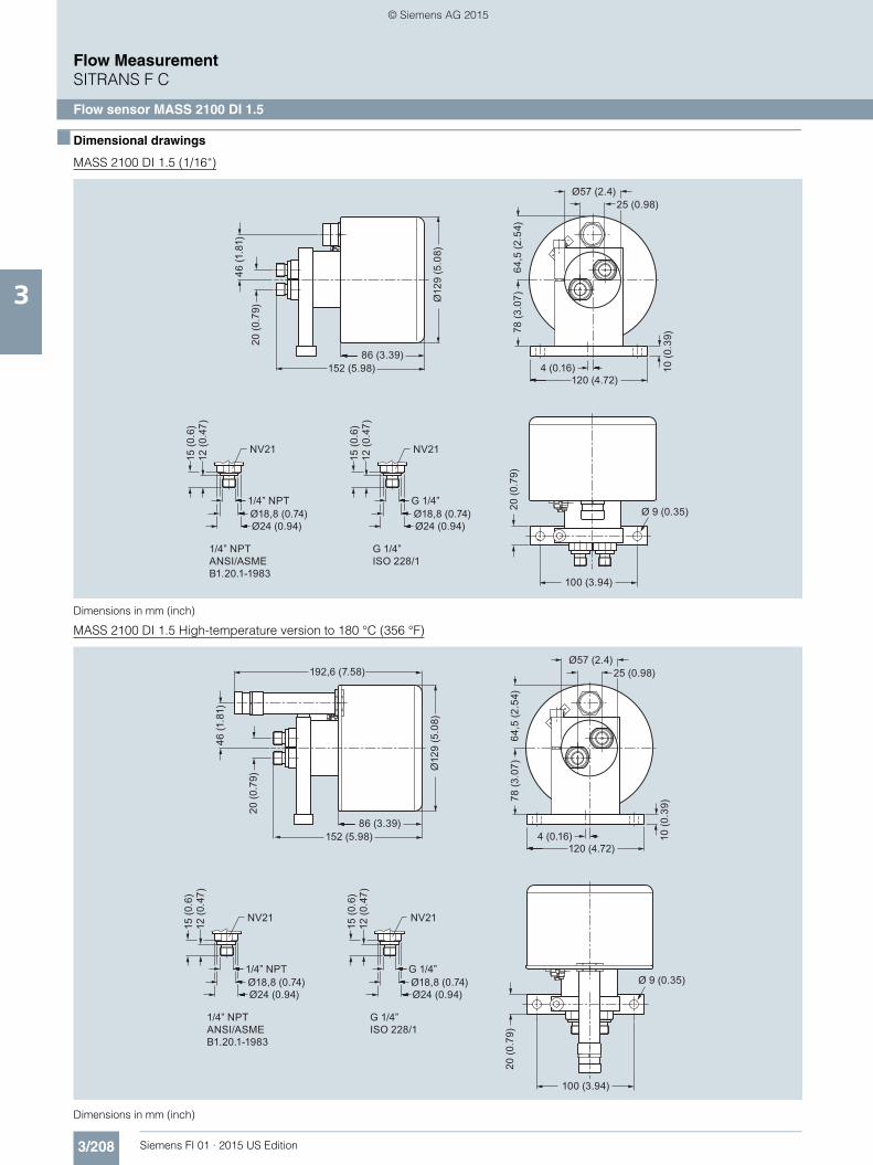
Selection and Ordering data Article No. Ord. code
SITRANS F C flow sensors MC2 7 ME 4 3 0 0 -
77777 - 7777 777
Click on the Article No. for the online confi-guration in the PIA Life Cycle Portal.
Nominal diameter
Stainless steel AISI 316Ti/1.4571
DN 100 1 DDN 150 1 E
Hastelloy C4/2.4610
DN 100 2 DDN 150 2 E
Nominal pressurePN 40 AClass 150 CClass 300 DClamps/screwed-connections F
Process connections
Flange EN 1092-1DN 80 (PN 40, PN 100) 2 2DN 100 (PN 40) 2 3DN 150 (PN 40) 2 4
Flange ASME/ANSI B16.53“ (class 150/300/600) 3 24“ (class 150/300) 3 36“ (class 150/300) 3 4
Dairy screwed connection to DIN 11851DN 80 (PN 25) 4 2DN 100 (PN 25) 4 3
Dairy clamp connection DIN 32676 (ISO 2852) Tri-clamp81 mm clamp (PN 10) 5 2100 mm clamp (PN 10) 5 3
Aseptic nut flange DIN 11864-2 form A for pipes dimensioned by DIN 11866DN 80 (3“) 6 3DN 100 (4“) 6 4
ConfigurationFlow (0.15% of rate) and density (5 kg/m3 [0.31 lb/ft3])
1
Flow (0.15% of rate) and density (1 kg/m3 [0.06 lb/ft3])
5
Ex-approval and cable glandNon-Ex, M20 x 1.5 AATEX, M20 x 1.5 B
CableNo cable A
CalibrationStandard 1
Dairy MLFB example Article No.MC2 sensor 7 M E 4 3 0 0 - 77777 - 7777
Sensor size DN 100. AISI 316Ti/1.4571 1 DNominal pressure: Clamps FDIN 11851, DN 100, PN 25 4 3
Configuration/calibration type: flow and density (5 kg/m3 [0.31 lb/ft3])
1
Without Ex appproval ANo cable AStandard calibration 1
Selection and Ordering data Order code
Additional informationPlease add “-Z“ to Article No. and specify Order code(s) and plain text.
Pressure testing certificate PED: 97/23/EC C11
Material certificate EN 10204-3.1 C12
Material certificate according to NACE C16
Tag name plate, stainless steel Y17
Tag name plate, plastic self-adhesive Y18
Customer-specified, matched pair (5 x 2) On request
Customer-specified calibration (5 x 2) On request
Customer-specified, matched pair (10 x 1) On request
Customer-specified calibration (10 x 1) On request
FI01_2015_us_Kap03.book Seite 228 Freitag, 20. Februar 2015 10:20 10
© Siemens AG 2015

3/229Siemens FI 01 · 2015 US Edition
Flow MeasurementSITRANS F C
Flow sensor MC2
3
■ Dimensional drawingsRemote design, flanged construction, DIN EN/ANSI
1) For Ex add 54 mm
Remote design, food industry fittings, DIN 11851
1) For Ex add 54 mm
Meter size
Process connec-tion size
L [mm (inch)]
G1)
[mm (inch)]
F[mm (inch)]
B[mm (inch)]
A[mm (inch)]
Weight[kg (lb)]
inch DN inch DN DIN 11864-2 form A
EN 1092-1PN 40
EN 1092-1PN 100
ANSI B16.5CL 150
ANSI B16.5CL 300
ANSI B16.5CL 600
4 100 3 80 1618 (63.70) 1640 (64.57) 1680 (66.14) 1660 (65.35) 1680 (66.14) 1702 (67.01) 500 (19.69)
215 (8.46)
131 (5.16)
170 (6.69)
84 (185)4 100 1463 (57.60) 1480 (58.27) 1530 (60.24) 1500 (59.06) 1520 (59.84) 1568 (61.73) 91 (201)6 150 N/A 1778 (69.92) N/A 1806 (71.10) 1826 (71.89) N/A 120 (265)
6 150 6 150 N/A 2040 (80.31) N/A 2070 (81.50) 2090 (82.28) N/A 613 (24.13)
285 (11.22)
190 (7.84)
260 (9.84)
260 (573)
Flow direction
Threaded stubsThreaded stubs
Food industry fittings DIN 11851
A
Ø80Ø80
F
G
B L
R
L
g
Meter size Process connection size L [mm (inch)]
g [mm (inch)]
G1) [mm (inch)]
F [mm (inch)]
B [mm (inch)]
A [mm (inch)]
R [mm (inch)]
Weight[kg (lb)]
inch DN inch DN4 100 3 80 Rd 110 x 1/6 1618 (63.70) 8 (0.31) 500 (19.69) 215 (8.46) 131 (5.16) 170 (6.69) 401 (15.79) 82 (180)
4 100 Rd 130 x ¼ 1463 (57.60) 10 (0.39) 314 (12.36) 86 (190)
FI01_2015_us_Kap03.book Seite 229 Freitag, 20. Februar 2015 10:20 10
© Siemens AG 2015

3/230 Siemens FI 01 · 2015 US Edition
Flow MeasurementSITRANS F C
Flow sensor MC2
3
Remote design, Tri-clamp DIN 32676 (ISO 2852)
Dimensions in mm (inch)
1) For Ex add 54 mm
Flow direction
A
8080F
G
B L
R
Meter size Process connection size
L [mm (inch)] 3
G1)
[mm (inch)]F [mm (inch)]
B [mm (inch)]
A [mm (inch)]
R [mm (inch)]
Weight[kg (lb)]
inch DN inch DN
4 100 3 80 1598 (62.91) 500 (19.69) 215 (8.46) 131 (5.16) 170 (6.69) 440 (17.32) 71 (157)
4 100 1448 (57.01) 365 (14.37) 69 (152)
FI01_2015_us_Kap03.book Seite 230 Freitag, 20. Februar 2015 10:20 10
© Siemens AG 2015

3/231Siemens FI 01 · 2015 US Edition
Flow MeasurementSITRANS F C
Flow sensor MC2
3
Process Connections• Flanges EN 1092-1/ANSI B16.5• Tri-Clamp DIN 32676 (ISO 2852)
- DN 100: Series 1• Food Industry fittings DIN 11851
The max. allowable operating pressure is a function of the pro-cess connection type, the fluid temperature, the bolts and the gaskets.
Pressure Rating• PN 16, PN 40
Class 150, Class 300
Housing as secondary containment • Max. 40 bar
Pressure Equipment Directive 97/23/EG• Conformity evaluation category III, fluid group 1
Corrosion resistance of measuring pipe material to measuring medium has to be considered.
Material strength for process connections
Pressure/temperature curves
DIN-Flanges stainless steel AISI 316Ti/1.4571 to DN 100 (4”)
ASME-Flanges stainless steel AISI 326Ti/1.4571 to DN 100 (4”)
For further information on the PED standard and requirements, see page 9/6.
Processconnection
Size PSmax.at 20 °C (68 °F)
TSmax. TSmin.
DN inch bar (psi g) °C (°F) °C (°F)
Thread acc.DIN 11851
100 4 25 (363) 140 (284) -40 (-40)
Tri-Clamp acc. DIN 32676
100 4 10 (145) 120 (248) -40 (-40)
PN 63
PN 40
PN 16
0 15010050-50
120
100
80
60
40
20
0
0 15010050-50
120
100
80
60
40
20
0
300 lb
150 lb
FI01_2015_us_Kap03.book Seite 231 Freitag, 20. Februar 2015 10:20 10
© Siemens AG 2015


![Flow Measurement SITRANS F X - Fine Controls (UK) Ltd PDFS... · Flow Measurement SITRANS F X ... A = cross-section area [m2] V = flow velocity [m/s] 1 2 d Q ... 1 Density compensation](https://img.pdfslide.us/doc/110x75/5b2569d07f8b9a517c8b4779/flow-measurement-sitrans-f-x-fine-controls-uk-ltd-pdfs-flow-measurement.jpg)