Embed Size (px)
Citation preview
Controllers
SensorsA
nalysersSam
plers
FlowLevel
PressureW
eb A
pp
Remote
controlD
atalog
ging
Accessories
Flow Leveland Pressure
Flow
For measurements in open channels to be installed upstream of constricted sections or shaped weirs664204 P Ultrasonic meters
For measurements in pressurised full section piping
Suitable for clean and dirty water with conductivity of at least 5 μS
Available with different types of flanges, Wafer, food connections
High power / low voltage or battery
69S103C Electromagnetic meters
For measurements in pressurised full section piping
Suitable for clean and dirty water with suspended solids up to a maximum of 10 g/l,non-conductive liquids, chemically aggressive roducts, oils
74Ultrasonic “transit time” Meters
For pressurised piping with liquids with a high content of suspended solids and sludge76Ultrasonic “Doppler” effect Meters
For measurements in open channels without restrictions, partially filled piping 78“Area x velocity” Meters

Controllers
SensorsA
nalysersSam
plers
FlowLevel
PressureW
eb A
pp
Remote
controlD
atalog
ging
Accessories
Ultrasonic measuring system with submerged sensor (Sonar)
for applications in the water treatment and industrial processes
Level
804204 L/U Level/differential meter to controlup to 5 pumps
Pressure
90Piezoresistive Transmitters
82Ultrasonic and Piezometric Sensors
83Radar and guided microwave Transmitters
86EchoSmart™ Sludge interface level measurement
88Piezoresistive Transmitters

Controllers
SensorsA
nalysersSam
plers
FlowLevel
PressureW
eb A
pp
Remote
controlD
atalog
ging
Accessories
66
FLOW METERS FOR OPEN CHANNELSWITH ULTRASONIC OR PIEZOMETRIC SENSOR
4204 P
• Flow rate measurements on channels with constrictionsor weirs
• Preset calculation exponents or freely programmableby user
• Possibility of calibration with table of up to 20 points,for nonlinear functions
• Dual data logger for instantaneous measurements andtotalized volumes
• Graphic display with indication of real-time values andstored values in graphical or tabular mode
• MODBUS RTU communication protocol
Main features
Dimensions: (L x H x P) 144 x 144 x 122.5mm – Weight: 1 KgDimensions /Weight
Display Backlit 128x64 graphic STN LCD
Controls 6 keys
DATA LOGGER Internal with 4 Mbit Flash
Serial output One (1) RS485 MODBUS RTU galvanically isolated
Analogue outputs
Relay outputs
Two (2) Programmable galvanically isolated
Five (5) for Thresholds – One (1) for Alarm (max.load 1A at 230Vac resistive)
Digital inputs Five (5) programmable
Power supply 100 ÷ 240Vac/dc 50-60Hz (Optional 24Vac/dc) – Transformer Insulation 4KV
Power consumption < 12W
Hardware features
Simultaneous indication of: Instantaneous flow (absolute + bar graph forpercentage of full scale), Totalized volume, Temperature, Status of digitaloutputs, Alarm events.In scrolling: Level, Status of analogue outputs, Resettable totalizer
Types of devices /exponents for calculatingPMD (primary measuringdevice) flow
Hardware features, software features and functions 4204 P
Flow 0 ÷ 9999 mc/h – Level 0.30 ÷ 5.00 mt. – Temperature 0 ÷ 100 °CMeasuring ranges
Flow: mc/h, lt/sec – Level: mt, cm, mm – Temperature: °CMeasurement unit
Measurement features
± 0.2% F.S.Precision
RETTANG (rectangular weir) / TRAPEZ (Cipolletti weir) / VENTURI (Venturichannel) / PARSHALL (Parshall channel) / L LEOPOLD (Leopold Lagco channel)/ STRAM. V (V-shaped weir) OTHER (freely programmable exponent). Tablewith 20 points for free programming
Absolute 9-digit (saved on non-resettable Flash PROM) – Partial 9-digit resettableTwo (2) totalizers

Controllers
SensorsA
nalysersSam
plers
FlowLevel
PressureW
eb A
pp
Remote
controlD
atalog
ging
Accessories
67
Hardware features, software features and functions 4204 P
Weirs
NAMUR 2.4 mA (with range 4/20mA)
Programming
Operating conditions
Alarm output
SecondaryPrimary
Flow / Temperature / LevelFlow / Temperature
Analogue outputs
Relay outputs (5)
Function – selectable Thresholds Pulses
Programming ON-OFF with hysteresis Scaler: 1, 10, 100 mc/hDuration: 250, 500, 1000, 2000 msec
Echo loss alarm
Alarm
Function
Time out (echo absence time): 00:00 ÷ 24:00 h
Temperature operating 0÷50°C ; storage and transport -25÷65°C
Humidity 10-95% non-condensing
Mechanical protection Closed IP66 EN60529
EMI / RFI CEI-EN55011 – 05/99
Quantity
0.00 ÷ 20.00 mA / 4.00 ÷ 20.00 mAType
Programming limits: Lower / UpperRange
500 OhmMaximum load
Recording interval 1/2/5/10/15/20/30/60 min 5/10/30 min. 1/2/6/12/24 h.
Instantaneous flow rate Totalized volume
Type Circular / Filling Circular / Filling
Display Graph: minimum, maximum andaverage values for the period and Zoom
Tabular
Measurement recording
Regular weirwith lateral constrictions
Rectangular weir withoutlateral constrictions
V-shaped weir
Trapezoidal weir
"Venturi" type constriction

Controllers
SensorsA
nalysersSam
plers
FlowLevel
PressureW
eb A
pp
Remote
controlD
atalog
ging
Accessories
68
Ultrasonic level measurement, without contact, suitable formeasurement of liquids, with integrated temperature sensorfor temperature compensation.
S425CFeatures and advantages
PVDF body resistant to aggressive environments
High resolution measurement 1mm
Double threaded connection
Immediate installation with disconnectable connector (IP67)
Modbus RTU Protocol
Technical specifications S425C
30 cm - 500 cmMeasuring ranges
Ultrasonic with automatic temperature compensationMeasuring method
14° ±1° Emission angle
± 0.2% of the measured distance (but not better than 2 mm)Accuracy
1 mmResolution
-10°C ÷ 75°COperating temperature
0.5 bar ÷ 1.5 barMaximum pressure
PVDF – PCVBody materials
IP67 ( IP68 optional)Protection grade
IP67 connectorElectrical connection
24 VdcPower supply
2 WPower consumption
5 meters (other on request)Cable
1”g.m and 1.5”g.m. Thread
Modbus RTU Standard Protocol RS485Signal interface
DIGITALSENSORS
Chemitec
PIEZOMETRIC TRANSDUCERThe absence of a separation liquid between themembrane and the pressure sensor, the “Dry-Pressure”measuring technology, allows you to have superiortechnological overpressure performance, small thermaldrifts, high stability and accuracy.
KPL / 36 XKY
ULTRASOUND LEVEL PROBE

Controllers
SensorsA
nalysersSam
plers
FlowLevel
PressureW
eb A
pp
Remote
controlD
atalog
ging
Accessories
69
The electromagnetic flow meter is used to measure theflow rate of conductive fluids and waste water.
The measurement is independent of the density,viscosity, temperature and pressure. The conductivity ofthe fluid must be greater than 5μS/cm.
The measuring tube must not be crossed by fluidscarrying solid bodies of high dimension that cannot beconsidered suspended solids. Load losses are absentand straight stretches reduced upstream anddownstream of the instrument are necessary.
Main application fields
• Sludge and water (primary, drinking and waste) treatment
• Control of civil and industrial wastes
• Measurement of industrial process water: chemical,paper, tanning, pharmaceutical, food
• Control of the chemical dosage
• Energy industry: generation and distribution
• Extractive industry: quarries, mines
• Environmental protection
MOUNTING
The electromagnetic meter must be installed so that thepipe is always completely filled with fluid. In the case of ahalf-empty pipe, the meter must be installed in anunderground channel, or in a “goose neck”, to achieve asiphon effect.
Installation may be vertical or horizontal but in the lattercase, ensure that there is no deposit of material on theelectrodes.
Installation must take place in such a position that thepiping cannot be emptied.
S103C
ELECTROMAGNETIC FLOW METERS

Controllers
SensorsA
nalysersSam
plers
FlowLevel
PressureW
eb A
pp
Remote
controlD
atalog
ging
Accessories
70
ELECTROMAGNETIC FLOW METERSDIAMETER SELECTION TABLE
ABACUS FOR THE OPTIMAL SELECTION OF THE MEASURING TUBE

Controllers
SensorsA
nalysersSam
plers
FlowLevel
PressureW
eb A
pp
Remote
controlD
atalog
ging
Accessories
71
ELECTROMAGNETIC FLOW METERS
CH 608 A/B/R ConverterThe 608 converter has been designed with the purpose of meetingall the requirements of modern water management systems.
It supports extended functions which make it perfectly suitable formeasuring and billing in civil, industrial and agricultural sector and forflow measurement in residual water treatment.
Hardware features, software features and functions CH 608 A/B/R
Compact on the sensor or remote on support, up to 100 m far from the sensorConverter installation
Epoxy painted aluminum, IP 67. With front window in toughened glass.Converter case
CH608A 90...264 Vac; 12/24 Vac/dcPower supply
Active analogue output 4 ÷ 20 mA ;Digital output for pulses maxim 1000 Hz duty cycle max 50% for instant flow,positive only, positive and negative
Output signals
Process -10°C ÷ 70°C ; Ambient -20°C ÷ 60°C; Storing -30°C ÷ 70°CTemperature
graphic LCD 128x64 pixels, visual area 50x25mm, backlitDisplay
simultaneous indications: counter, instant variable and status flags
4 totalizers available (2 positive totals and 2 negative totals)
– with 4 push buttons for non-billing applications – through IrCOM interface and dedicated software – via RS485 MODBUS RTU protocol
Programming
4 MB flash memory, 200,000 lines of data (one line includes: instant flow, 2counters, date, time, temperature)
Process data logger
64 kB EEPROM, 2000 lines of data (one line includes: date, time, temperature,error codes, user actions with changes made)
Diagnostics data logger
Programmable digital output for: – Maximum pulses1000 Hz duty cycle max 50% for negative flow;– Negative flow indication;– Cumulative alarm
Digital output in active frequency 0 ÷ 10 kHz
CH608B Battery powered or 12/24 Vac/dc ; Expected battery life T=0 / 50°C( 32 / 122 °F) ; Internal battery pack 6-10 years
CH608R Rechargeable battery + 10 Watt photovoltaic panel

Controllers
SensorsA
nalysersSam
plers
FlowLevel
PressureW
eb A
pp
Remote
controlD
atalog
ging
Accessories
72
ELECTROMAGNETIC FLOW METERS
CH2200 CH2500 CH2400 CH1000
DN15…DN400 DN 450…DN2000 DN25…DN100 DN25…DN300
Connection to process
Dimensions
UNI 2223on request ANSI 150; ANSI 300;
AWWA CI.D; ANSI 600
TRICLAMPon request DIN 11851;
SMS fil. male
WAFERConnections
PN10…PN64 PN10…PN40 PN16…PN40Pressure
0.2% 0.2% 0.2% 0.2%
Accuracy
With liquid speed ≥ 0.2 m/s
PFTEon request EBANITE
EBANITEon request PTFE
PFTE PFTEon request EBANITE
Materials
Inner lining
HASTELLOY Con request Titanium, Tantalum, Platinum
HASTELLOY Con request Titanium, Tantalum
Electrodes
3 x DN15…404 x DN50…400
4 2 3 x DN15…404 x DN50…300
No. of electrodes
Carbon steel AISI 304 Carbon steelBody
Carbon steel
-25 ÷ 80°C -25 ÷ 80°C -25 ÷ 80°C -25 ÷ 80°C
AISI 304 –Flange
Process temperature
Compact version with converter integralwith the sensor
-25 ÷ 200°C -25 ÷ 200°C -25 ÷ 130°C -25 ÷ 130°C Separated versionwith converter separatedfrom the sensor
IP67 IP67 IP67 IP67
Protection grade
Compact version with converter integralwith the sensor
IP68 IP68 IP68 IP68 Separated versionwith converter separatedfrom the sensor
on request on request on request on request
Certifications
ATEX II 2 GD EExmb IIC T4 U

Controllers
SensorsA
nalysersSam
plers
FlowLevel
PressureW
eb A
pp
Remote
controlD
atalog
ging
Accessories
73
CH2660 CH2770 CH2700 CH1222CH500
Connection to process
DN80…DN500 DN100…DN4000 DN100…DN4000 DN40…DN1000DN3…DN20
INSERTIONTHREADED
INSERTIONFLANGED
UNI2278 DN40
INSERTIONWelded
sleeve 2”
INSERTIONGASon request NPT;
TRICLAMP; DIN 11851
PN10 PN25 PN20PN16
2% 2% 2% 2%
Accuracy
0,2%
PFTE PFTE PFTE PFTEPFTE
AISI316 L AISI316 L AISI316 L AISI316 LAISI316 L
Materials
2 2 2 22
AISI 304 AISI 304 AISI 304 AISI 304AISI 304
– Carbon steel Ball valve AISI 316 LAISI 316 L
-25 ÷ 80°C -25 ÷ 80°C -25 ÷ 80°C -25 ÷ 80°C
Process temperature
-25 ÷ 80°C
-25 ÷ 130°C -25 ÷ 130°C -25 ÷ 130°C -25 ÷ 130°C -25 ÷ 130°C
IP67 IP67 IP67 IP67
Protection grade
IP67
on request on request on request on request
Certifications
on request
IP68 IP68 IP68 IP68 IP68

Controllers
SensorsA
nalysersSam
plers
FlowLevel
PressureW
eb A
pp
Remote
controlD
atalog
ging
Accessories
74
The flow measurement systems S101F and200H consist of a digital converter and twoultrasonic clamp-on or insertion transducers.
The transit time of a fluid inside a pipe with acylindrical section is the operating principle onwhich the instrument is based to calculate thevalue of the instantaneous flow rate.
DSP technology
Digital Signal Processing technology (DSP),ensures low sensitivity of the system to anypotential disturbing factors.
The pipe dimensions may vary from 20 to 4000mm (by using different transducers) whileliquids can be: ultra-pure, drinking water,chemicals, dirty water, cooling water, riverwater etc.
As far as the transducers are applied externallyto the pipe, are not in contact with the liquidand have no moving parts, the transmitter willnot be damaged by wear, deposits or pressure.
All the configuration values entered by user aresaved on the EEPROM, which is password-protected to prevent accidental changes.
Mod. S101F for fixed installation
Mod. 200H portable
DSP technology - diagram
FIXED OR PORTABLE ULTRASONIC “TRANSIT TIME”FLOW METERS FOR PRESSURIZED LINES

Controllers
SensorsA
nalysersSam
plers
FlowLevel
PressureW
eb A
pp
Remote
controlD
atalog
ging
Accessories
75
Hardware features, software features and functions
S101F 200HModels
from DN 20 to 4000mm from DN 20 to 4000mmMeasurement on pipes
steel, stainless steel, cast iron, copper, PVC, aluminium, fibreglass-reinforced plastic (cement with insertion transducers)
Piping material
metres, cubic metres, litres, feet, cubic feet, U.S. gallons, imperialgallons, oil barrels, U.S. oil barrels, imperial oil barrels, millions ofU.S. gallons
Measurement units (user selectable)
virtually all liquids that transmit sound wavesType of liquid
± 32m/sSpeed range
0.5% ; repeatability: 0.2% ; total accuracy ± 1%Linearity
programmable from 1 to 999sResponse time
2 x 2016 alphanumeric characters 4 lines 16 alphanumeric charactersDisplay
4 membrane buttons 8 buttons Keypad
instantaneous flow rate; total flow; otherDisplayed data
7 digit totalizer; 7 digit direct flow counter; 7 digit reverse flowcounter
Internal volume totalizers
setup and change settings password protectedSafety
optional storage capacity up to 16GBInternal data logger
4 ÷ 20 mA or 0 ÷ 20 mA –Selectable output
programmable 0 ÷ 9999 Hz –Frequency output
for pulse or alarm totalizer –Output relay
RS485Signal interface
MODBUS RTU; MODBUS ASCIICommunication protocol
230Vac / 24Vdc
–
external p. supply 100 ± 253Vac
three (3) AAA Ni-mH integratedwith autonomy >10 hours
Power supply
Rechargeable batteries
wall-mounted portableMounting
aluminium ABSHousing
215 x 158 x 74 mm case 460 x 400 x 110 mmDimensions (L x H x P)
3.1 kg 4.5 kgWeight
-30 ÷ 80°C –Operating temperature
85% RH non-condensing (40°C) –Maximum humidity
sensor 0 ÷ 150°C –Process temperature
98% RH non-condensing (40°C) –Sensor humidity

Controllers
SensorsA
nalysersSam
plers
FlowLevel
PressureW
eb A
pp
Remote
controlD
atalog
ging
Accessories
76
FIXED OR PORTABLE "DOPPLER" EFFECTFLOW METERS FOR PRESSURIZED LINES
The DFM-5.0 Doppler effect flow transmitter is suitable formost liquids, such as water, waste water, chemical liquids,sludge and viscous liquids. It controls, indicates, totalizesand transmits the flow rate in gallons, liters or othermeasurement units.
The PDFM-5.0 Doppler effect flow meter is suitable formonitoring a flow rate or to identify problems encounteredin a closed pipe.
Operating principle
The sensor transmits high frequency sounds into theliquid, through the pipe wall. The pulses are reflectedand sent back to the sensor by solid particles and airbubbles present into the fluid. Because of the fluid’smovement, the reflected sounds return to the sensorwith an altered frequency (Doppler effect). DFM-5.0 andPDFM-5.0 continuously measures the frequencydeviation in order to ensure very precise measurement ofthe velocity of the fluid and thus the flow rate.
Installation
Can be done without stopping the plant. There is nocontact between the sensitive element and the fluidwhose flow rate is to be measured and no cutting ordrilling are required on the pipe. The sensor is of aparallelepiped shape, is not affected by dirt or depositsand is easy to mount on the outside of a pipe using atape.
Easy programming
Using the program buttons can be easily accessed theprogramming menu where it is possible to select thediameter of the pipe, to set the engineering units(gallons, litres etc.), the totalization velocity, the relays,the sensitivity and the damping. Totalisation andcalibration data are password-protected and alsoprotected against power failures.
Application
DFM-5.0 is recommended for liquids containing solidsor air bubbles; the sensor is mounted on the outside of apipe made off steel, iron, PVC or ABS.
PDFM-5.0 is an ideal instrument for evaluating theperformance of flow meters inserted in line. Can beinstalled, calibrated and commissioned in a few minutesand, therefore, used as a temporary substitution of an inline transmitter.
DFM-5.0 fixed meter
PDFM-5.0 portable meter
operating principle - diagram
Controllers
SensorsA
nalysersSam
plers
FlowLevel
PressureW
eb A
pp
Remote
controlD
atalog
ging
Accessories
77
Sensor
Operating temperature
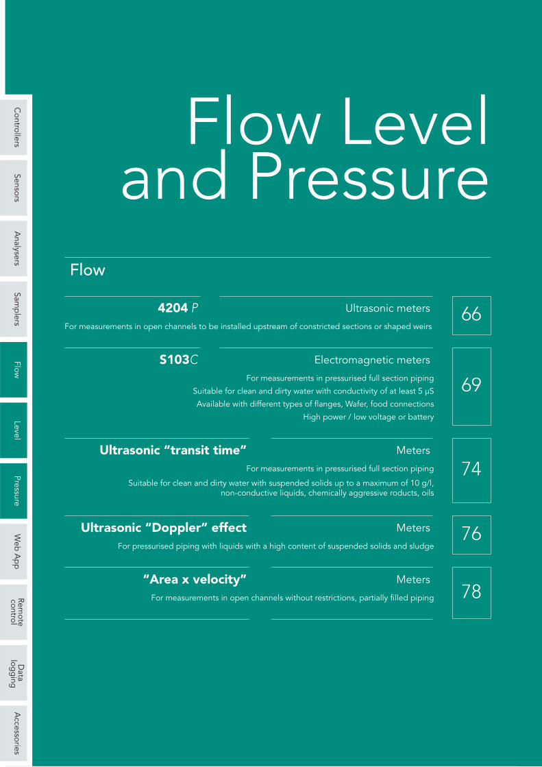
Hardware features, software features and functions
DFM-5.0 PDFM-5.0Models
0.08 ÷ 112.2 m/sec 0.03 ÷ 112.2 m/secMeasuring range
± 2% (suspended solids or air bubbles with a min. diameter of 100 microns andconcentration of 75 ppm are required)
Precision
1/2” ÷ 180” (12.7 mm ÷ 4.5 m)Piping
± 0.1% / ± 0.5%Repeatability / Linearity
adjustable / adjustableSensitivity / Damping
on sensor, signal and power supplyProtection
LCD 16 alphanumeric digitsDisplay
optional
2,000,000 recordable points
programmable
300,000 recordable pointsprinted with time or formatted report ofthe flow rate with total, minimum,maximum and average (time if required)
Data logger
Capacity
100 ÷ 160 Vca; 180 ÷ 260 Vca; 12 or 24 Vdc
–
integrated 12 Vdc AAA recharge-able batteries, 24 hours autonomy
built-in, network selectable 115or 230 Vac or external 12 Vdc
Power supply
Battery charger
wall portableMounting
Cable (optional)
Installation kit stainless steel tape and 150 g of silicone paste
watertight NEMA 4X (IP67),fibreglass and transparentfront
ABS (IP 67) with caseHousing
188 x 278 x 130 mm 110 x 204 x 41 mmDimensions (L x H x P)
– approx. 4 kgWeight
up to 150 m 15 m
-5 ÷ 40°C -23 ÷ 60°C
SE4 A – external installation,for piping of internal diameterfrom 12.7 mm to 4.5 m
PSE4 – external installation, forpiping of internal diameter from12.5 mm to 4.5 m or higher
flow rate value 4 digits (19 mm); totalization; menu; status; signalIndication
Calibration keypad 3 frontal buttons 5 frontal buttons
4 ÷ 20 mA; 1000 ohm 4 ÷ 20 mA; 500 ohm(when powered by mains)
Output
USB port
Two (2) SPDT; 5A;programmable (for alarms and/orpulses proportional to the flow rate)
–Control relays
optional included

Controllers
SensorsA
nalysersSam
plers
FlowLevel
PressureW
eb A
pp
Remote
controlD
atalog
ging
Accessories
78
FIXED OR PORTABLE “AREA X VELOCITY” FLOW METERS
The AVFM 5.0 system simultaneously measures the leveland the velocity of the fluid in order to calculate the flowrate into an open channel or a pipe.
The STINGRAY portable instrument works for a very longperiod of time powered by alkaline batteries and storesmeasurements of water level, velocity and temperature inopen channels and in partially filled or pressurised pipeswithout the need for constrictions or weirs.
Operating principle
The immersible ultrasonic sensor continuously monitorsboth the velocity and the level of the channel or piping bytransmitting high frequency sounds into the liquid, throughthe pipe wall. The pulses are reflected and sent back tothe sensor by solid particles and air bubbles present intothe fluid. Because of the fluid‘s movement, the reflectedsounds return to the sensor with an altered frequency(Doppler effect).
The best accuracy is achieved if the flow does not have anexcessive turbulence and the velocity on the sensor is notless than 1 m/sec. The channel, right upstream of thesensor, must not have abrupt changes in the level of thebottom and a slope of no more than 3%. The conditionsdownstream of the sensor do not affect the measurementif the surface profile is not changed right above the sensoritself.
Easy calibration
To calibrate AVFM 5.0 just insert the pipe diameter or thechannel width and choose the measurement unit from themenu. The flow rate, level and velocity can be expressedin gallons, litres, ft³ or m³. The calibration parametersremain stored even in the absence of tension.
For STINGRAY no calibration is required. On the frontthere is a bar indicating the velocity, level, temperature,battery status and finally the used/available memory. Thedisplay automatically turns off after 60 seconds to savepower. The software allows the user to set the samplingintervals, to download the files and to get an indication ofthe variables. The logger displays the files and thecalculated velocity in trend graphs and tables, includingthe minimum and maximum values, the average and totalflow rate in normal measurement units.
AVFM 5.0 fixed meter
STINGRAY portable meter
operating principle - diagram

Controllers
SensorsA
nalysersSam
plers
FlowLevel
PressureW
eb A
pp
Remote
controlD
atalog
ging
Accessories
79
Sensor
Operating temperature
Hardware features, software features and functions
AVFM 5.0 STINGRAYModels
Level ± 0.25% of the range ; Velocity ±2% of the readingPrecision
± 2% (suspended solids or air bubbles with a min. diameter of 100 microns andconcentration of 75 ppm are required)
Precision
± 0.1% / ± 0.5%Repeatability / Linearity
adjustable / adjustableSensitivity / Damping
on sensor, signal and power supplyProtection
LCD 16 alphanumeric digitsDisplay
optional
2,000,000 recordable points
programmable
300,000 recordable pointsprinted with time or formatted report ofthe flow rate with total, minimum,maximum and average (time if required)
Data logger
Capacity
100 ÷ 160 Vca; 180 ÷ 260 Vca; 12 or 24 Vcc
–
integrated 12 Vdc AAA recharge-able batteries, 24 hours autonomy
built-in, network selectable 115or 230 Vac or external 12 Vdc
Power supply
Battery charger
wall portableMounting
Cable (optional)
watertight NEMA 4X (IP67),fibreglass and transparentfront
ABS (IP 67) with caseHousing
188 x 278 x 130 mm 208 x 166 x 86 mmDimensions (L x H x P)
– approx. 4 kgWeight
up to 150 m 15 m
-5 ÷ 40°C -23 ÷ 60°C
-40 ÷ 95°C -40 ÷ 120 °COperating temperature
Standard sensor, QZ02Lsubmersible – velocity andlevel measurements. Separateversions or for hightemperatures on request
QZ02L Submersible level-velocity ultrasonic sensor. Forhigh temperatures on request
flow rate value 4 digits (19 mm); totalization; menu; status; signalIndication
Calibration keypad 3 frontal buttons 5 frontal buttons
4 ÷ 20 mA; 1000 ohm 4 ÷ 20 mA; 500 ohm(when powered by mains)
Output
USB port
Two (2) SPDT; 5A;programmable (for alarms and/orpulses proportional to the flow rate)
–Control relays
optional included
Controllers
SensorsA
nalysersSam
plers
FlowLevel
PressureW
eb A
pp
Remote
controlD
atalog
ging
Accessories
80
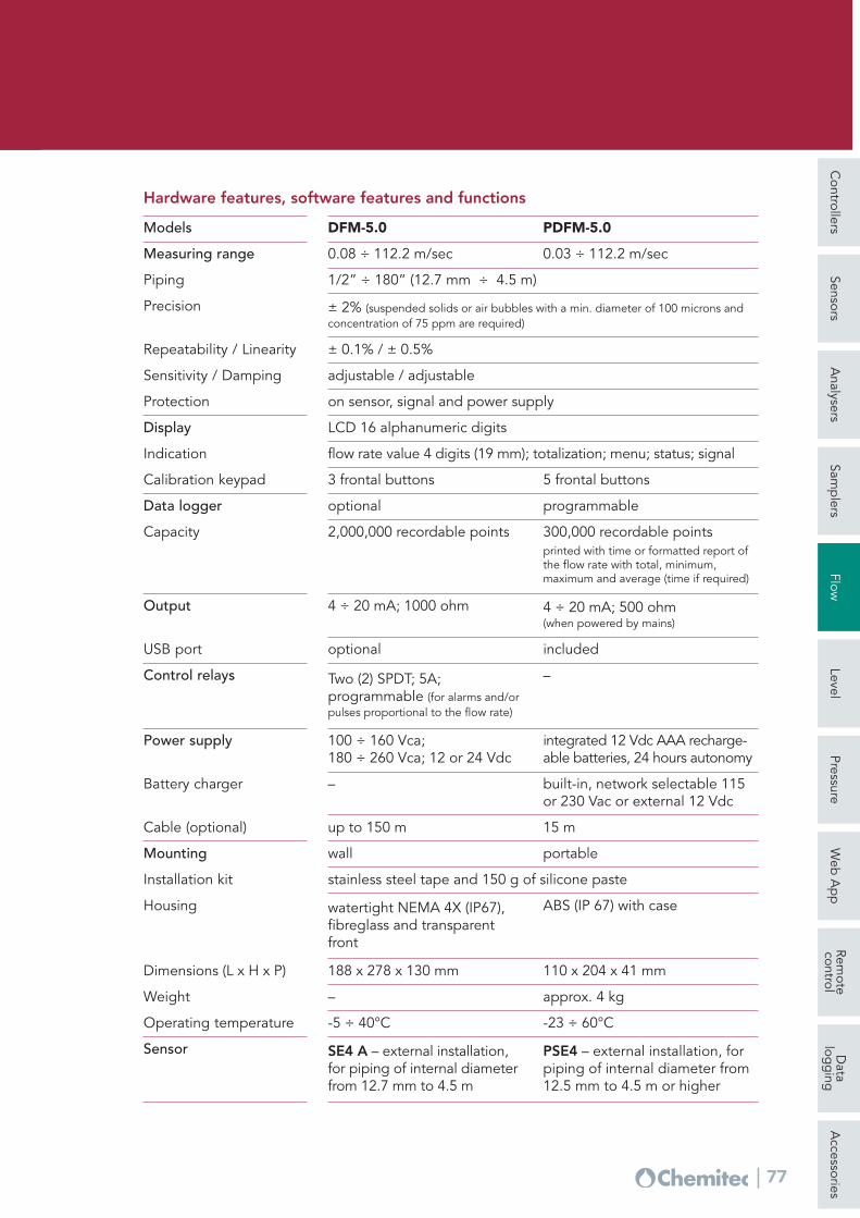
4204 L/UMain features
• Ultrasonic levelmeasurement, singlelevel, double level,differential level
• Automatic temperaturecompensation
• Programming keypadwith 6 bubble-keys
• Graphic display
• Pumps operation:single, rotation ortimed
• RS485 MODBUS RTUserial output
• 2 Programmableanalogue outputs
• 5 Relay outputs forintervention thresholdsfor pumps control
• 1 Relay output forinstrument anomalyalarm / for flowtotalization / or level 2alarm
• 5 Digital inputs pumps operation /anomaly
LEVEL METERWITH ULTRASONIC OR PIEZOMETRIC SENSOR
Distanzamassima
Zonamorta Sonda
100%
LivelloMax.
LivelloMin.
Livello
Spazio Range
0%
Main operating settings
DEAD ZONE Distance of insensitivity of thetransducer measured from the active surface of thetransducer. (~ 30/40/70 cm in relation to the type ofprobe connected)DISTANCE Interval between the transducer faceand the liquid surface inside the tank or equivalent.The distance cannot be higher than the range of thetransducer.RANGE Measurement interval. Freely programmablewithin the range of the transducer - dead zone; istherefore the theoretical operating range of theSystem.
LEVEL The interval between the zero level and theliquid surface level inside the tank or equivalent.
MAX LEV It is the MAX operating level above whichthe system gives an alarm.
MIN LEV It is the MIN operating level below whichthe system gives an alarm.
MAX DISTANCE Max distance between thetransducer surface and the vacuum level (zero).
SPACE Interval between the surface of the liquidinside the tank or equivalent and the dead zone.
Deadzone
Max.distance
Level
Space Range
Probe
Max.level
Min.level

Controllers
SensorsA
nalysersSam
plers
FlowLevel
PressureW
eb A
pp
Remote
controlD
atalog
ging
Accessories
81
Hardware features, software features and functions 4204 L/U
NAMUR 2.4 mA (with range 4/20mA)
Programming
Operating conditions
Alarm output
SecondaryPrimary
Dimensions: (L x H x P) 144 x 144 x 122.5mm – Weight: 1 KgDimensions /Weight
Level / TemperatureLevel
Display
Level 0.30 ÷ 5.00/0.40 ÷ 8.00/ 0.70 ÷ 12.00 mt (in relation to the probe connected)
Temperature -25°C - +75°C
Measuring ranges
Level: mt, cm, mm – Temperature: °CMeasurement unit
Measurement features
Backlit 128x64 graphic STN LCD
Controls 6 keys
DATA LOGGER Internal with 4 Mbit Flash
Serial output One (1) RS485 MODBUS RTU galvanically isolated
Analogue outputs
Relay outputs
Two (2) Programmable galvanically isolated
Five (5) for Thresholds – One (1) for Alarm (max.load 1A at 230Vac resistive)
Digital inputs Five (5) programmable
Power supply 100 ÷ 240Vac/dc 50-60Hz (Optional 24Vac/dc) – Transformer Insulation 4KV
Power consumption < 12W
Analogue outputs
Relay outputs (5)
Function – selectable Thresholds Pulses
Echo loss alarm
Alarm
Function
Time out (echo absence time): 00:00 ÷ 24:00 h
Temperature operating 0÷50°C ; storage and transport -25÷65°C
Humidity 10-95% non-condensing
Mechanical protection Closed IP66 EN60529
EMI / RFI CEI-EN55011 – 05/99
Quantity
0.00 ÷ 20.00 mA / 4.00 ÷ 20.00 mAType
Programming limits: Lower / UpperRange
500 OhmMaximum load
1°Output: Level / Temperature – 2° Output: level 2, differential, temperature
Hardware features
Simultaneous indication of: Level (absolute / differential + bar graph forpercentage of full scale), Temperature, Status of digital outputs (led), Alarmevents.In scrolling: Level 2, Status of analogue outputs
± 0.2% F.S.Precision

Controllers
SensorsA
nalysersSam
plers
FlowLevel
PressureW
eb A
pp
Remote
controlD
atalog
ging
Accessories
82
Modbus RTU Standard Protocol RS485Signal interface
Technical specifications S425C
30 cm - 500 cm 40 cm - 800 cm 70 cm - 1200 cmMeasuring ranges
S425C–5 S425C–8 S425C 12Models
Ultrasonic with automatic temperature compensationMeasuring method
14° ±1° 7° ±1° Emission angle
± 0.2% of the measured distance (but not better than 2 mm)Accuracy
1 mmResolution
-10°C ÷ 75°COperating temperature
0.5 bar ÷ 1.5 barMaximum pressure
PVDF – PCVBody materials
IP67 ( IP68 optional )Protection grade
screw connectorElectrical connection
24 VdcPower supply
2 WPower consumption
5 meters 8 meters 12 metersCable
optional max load 500 ohmCurrent output
1”g.m ; 1.5”g.m. 1”g.mThread
Ultrasonic level measurement, without contact, suitable formeasurement of liquids, with integrated temperature sensorfor temperature compensation.
S425CFeatures and advantages
PVDF body resistant to aggressive environments
High resolution measurement 1mm
Double threaded connection
Immediate installation with disconnectable connettor (IP67)
Modbus RTU Protocol
DIGITALSENSORS
Chemitec
PIEZOMETRIC TRANSDUCERThe absence of a separation liquid between themembrane and the pressure sensor, the “Dry-Pressure”measuring technology, allows you to have superiortechnological overpressure performance, small thermaldrifts, high stability and accuracy.
KPL / 36 XKY
ULTRASOUND LEVEL PROBE

Controllers
SensorsA
nalysersSam
plers
FlowLevel
PressureW
eb A
pp
Remote
controlD
atalog
ging
Accessories
83
The measurement technology used by the METER level transmitter isthe emission of a short ultrasonic pulse. The ultrasonic wave propagatestowards the surface of the product to be measured, bouncing back onits surface towards the sensor. The time interval that elapses betweenthe emission and the reception of the wave is called the flight time andit is proportional to the distance measured, therefore to the level.
METERAvailable versions
RANGE 5M 4 wires, 2 relays ; 4 wires, 2 relays, MODBUS2 wires; 2 wires HART; 2 wires HART, ATEX
RANGE 8M 2 wires; 2 wires, HART, ATEX4 wires, 2 relays; 4 wires, 2 relays, MODBUS
Programming takes place via a removable module (keypad/display).Once programming is complete, it is possible to remove the module(keypad/display), leaving the level transmitter operational but with nodisplay on board.
0.25 ÷ 5 m ; max. 0.4 ÷ 8 m (Distances expressed are valid formeasurements of perfectly reflective surfaces, otherwise the maximummeasurable distance is reduced)
Measuring range
Temp. compensation
Hardware features, software features and functions METER
removable module with 4 keys and dot matrix LCD (or via HART / MODBUSRTU on request) Programming / Display
PC or Al / PP or PVDF wetted part (ATEX certified versions only of PVDF)Housing material
2”GAS M (PP flange DN80 opt.)Mechanical installation
2 wires version 20 ÷ 30Vdc ; 4 wires version 24VdcPower supply
2 wires version 0.6 W ; 4 wires version 1.5 WPower Consumption
4÷20mA, max 750ohm (4 wires version)Analogue output
ATEX II 1/2G Ex ia II C T6Ex-proof
4 wires version two (2) 3A 230Vac (n.a.)Output relays
2 wires version (opt.) HART ; 4 wires version MODBUS RTUDigital communication
IP67 Protection grade
digital between -30 ÷ +80°C
Accuracy ±0.5% (of the measured distance) but not less than ±3mm
Resolution 1 mm
Operating temperature -30 ÷ +70°C; +80°C non-continuous
Pressure from 0.5 to 1.5 bar (absolute)
ULTRASONIC LEVEL TRANSMITTERS

Controllers
SensorsA
nalysersSam
plers
FlowLevel
PressureW
eb A
pp
Remote
controlD
atalog
ging
Accessories
84
Hardware features, software features and functions RPL
Features
– Continuous level measurementwithout contact of solids,liquids, pastes and sludges
– Measurement independentfrom physical featuresvariations of the product
– Dust, vapours and temperaturevariations do not interfere withmeasurement
– Coniguration with guidedmenu using the alphanumericdisplay
– 2/4 wires technology
RPL51 RPL52 RPL55 RPL56 RPL58Models
with threaded fitting with threaded fittingand emission cone
Type
Highlyaggressiveliquids withnondemandingprocessconditions
Highlyaggressiveliquids
Highlyaggressiveliquids
Extreme processconditions
Extreme processconditions
Applications
30 m 30 m 10 m 30 m 70 mMeasuring range
± 10 mm ± 10 mm ± 5 mm ± 3 mm ± 15 mmAccuracy
G 1” ½ APVDF
FlangeAISI 316LDN50, DN80,DN100,DN150 PN16
G 1” ½ APTFE
G 1” ½ AAISI 316LAdditionalflange
G 1” ½ AAdditionalflange
Connection to process
PPPTFE
PTFE PTFE AISI 316LPTFE
AISI 316LPTFE
Antenna material
6GHz 6GHz 6GHz 26GHz 26GHzFrequency range
2/4 wires ; 4 ÷ 20mA ; HARTOutput signal
IP67Protection grade
RPL devices are instruments for level measurement without contact with theproduct. The radar pulses emitted by the antenna are relected from the surfaceof the product and subsequently received by the antenna itself. The integratedmanagement system of the RPL devices uses the flight time to obtain the distanceof the surface of the product from the probe and, consequently, the level.
RPL
-20 ÷100° C-20 ÷ 120° C
-1 ÷ 3 bar -1 ÷ 16 bar -1 ÷ 3 bar -1 ÷ 40 bar -1 ÷ 16 bar
-40 ÷ 150 °C -40 ÷ 120° C -40 ÷ 200 °C -40 ÷ 200 °COperating temperature
Process pressure
MICROWAVE LEVEL TRANSMITTERS (RADAR)

Controllers
SensorsA
nalysersSam
plers
FlowLevel
PressureW
eb A
pp
Remote
controlD
atalog
ging
Accessories
85
Protection grade
Process pressure
Connection to process(AISI 316L)
Measuring range
The instrument emits high frequency pulses. The “GODA” measuringtechnique, combined with the management system, allows the RWL units tobe used even in particularly demanding process conditions such as: hightemperature, high pressure, low dielectric constant etc.
RWLFeatures
Continuous measurement of dust levels on solid materials of variableconsistency and liquids (dust, vapours and temperature variations do notinterfere with the measurement)
Available probes:– rope probes for measuring loose solids, measuring range up to 30 m– rod probes in particular for measuring liquids, measuring range up to 6m– coaxial probes for liquid products, measuring range up to 6m
Configuration with guided menu and calibration by means of entering theempty and full distances without product movement, through alphanumericdisplay
Storage and recognition system of false signals
level and curve measurement of echo signal shown on alphanumeric displayDisplay
CENELECCertifications
HART optionalCommunication protocol
rope 30 mrod 3 m
rod 3 m coaxial 3 m rope 30 mrod 3 m
± 10 mmAccuracy
-40 ÷ 150 °C -40 ÷ 250 °COperating temperature
-1 ÷ 40 bar
AISI 316L / PTFERope/Rod material
Gaskets Viton ( -30 ÷ 130°C) ; Kalrez ( -40 ÷ 150°C)
1 ½" G2" G
DN50 PN16DN80 PN16DN100 PN16DN150 PN16
1 ½" G2" G
1 ½" G2" G
IP67
Hardware features, software features and functions RWL
RWL51 RWL52 RWL53 RWL54Models
rope Ø 4/6mmrod Ø 10mm
for liquids/solids for liquids/solids for liquids withlow dielectricconstant
for liquids withhigh processtemperatures /pressures
rod Ø 10mm coaxialØ 28mm
rope Ø 4/6mmrod Ø 10mm
Probe type
Applications
MICROWAVE LEVEL TRANSMITTERS (RADAR)

Controllers
SensorsA
nalysersSam
plers
FlowLevel
PressureW
eb A
pp
Remote
controlD
atalog
ging
Accessories
86
SLUDGE INTERFACE LEVEL METER
Control unit
Power supply unit
Level Sensor Level (otp. Turbidity)Sensor with wiper
EchoSmart™ Sensors
EchoSmart sensors generate and process the ultrasoundsignal for real-time measurement with maximum flexibilityof the liquid/solid interface.
They have greater signal control and the performance ofthe control algorithms, specifically developed and fieldtested, has been confirmed in the U.S. and around theworld.
Flexibility
Available options – EchoSmart sensor in conjunction with the EchoSmart
control unit– EchoSmart with sensor in conjunction with the power
supply unit (remote programming via EchoSmartConsole SW)
EchoSmart Networks – Network interconnection of up to 128 EchoSmart
sensors – Communication via RS-485 or Ethernet – RF compatible ZigBee network integration
Easy to use– Large display with intuitive screens for quick entry of
parameters – Soft Keys operation with Guide for all settings– Initialisation and automatic calibration for quick start-
up with no process interruption
EchoSmart™Ultrasonic measuring system withsubmerged sensor (Sonar)
Controllers
SensorsA
nalysersSam
plers
FlowLevel
PressureW
eb A
pp
Remote
controlD
atalog
ging
Accessories
87
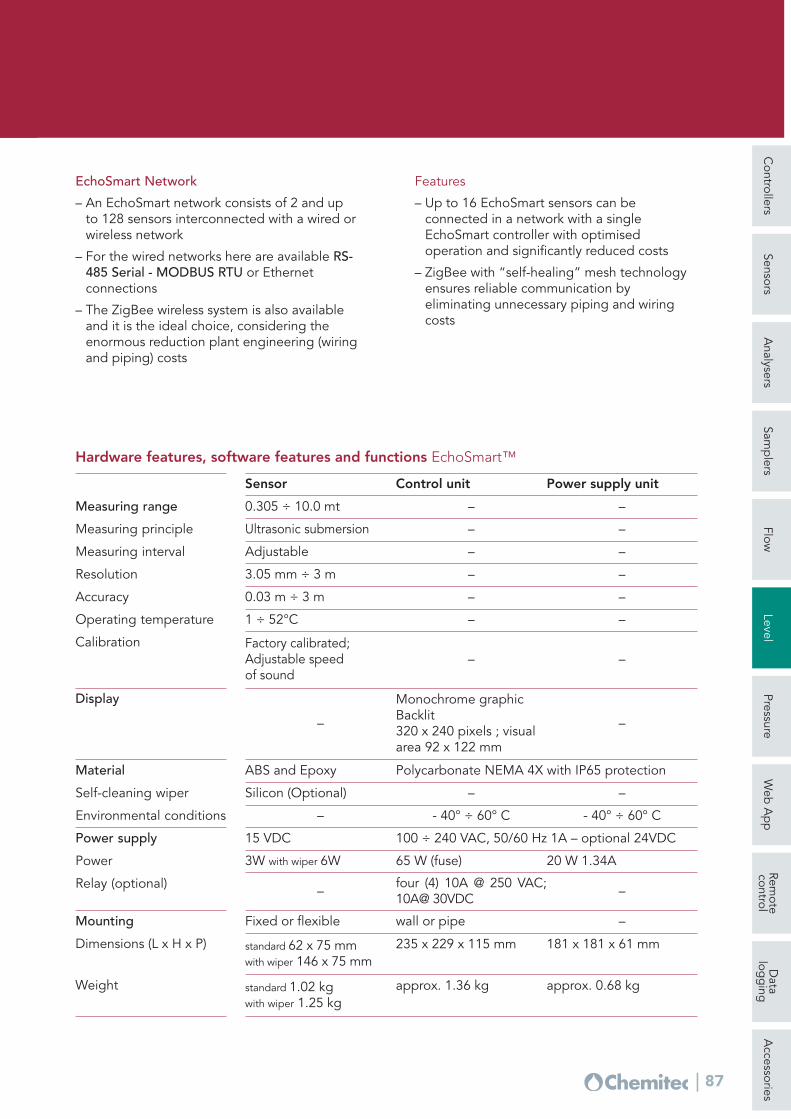
EchoSmart Network
– An EchoSmart network consists of 2 and upto 128 sensors interconnected with a wired orwireless network
– For the wired networks here are available RS-485 Serial - MODBUS RTU or Ethernetconnections
– The ZigBee wireless system is also availableand it is the ideal choice, considering theenormous reduction plant engineering (wiringand piping) costs
Features
– Up to 16 EchoSmart sensors can beconnected in a network with a singleEchoSmart controller with optimisedoperation and significantly reduced costs
– ZigBee with “self-healing” mesh technologyensures reliable communication byeliminating unnecessary piping and wiringcosts
Fixed or flexible wall or pipe –Mounting
standard 62 x 75 mmwith wiper 146 x 75 mm
235 x 229 x 115 mm 181 x 181 x 61 mmDimensions (L x H x P)
standard 1.02 kgwith wiper 1.25 kg
approx. 1.36 kg approx. 0.68 kgWeight
15 VDC 100 ÷ 240 VAC, 50/60 Hz 1A – optional 24VDCPower supply
3W with wiper 6W 65 W (fuse) 20 W 1.34APower
– four (4) 10A @ 250 VAC;10A@ 30VDC –Relay (optional)
ABS and Epoxy Polycarbonate NEMA 4X with IP65 protection
Silicon (Optional) – –
Material
Self-cleaning wiper
– - 40° ÷ 60° C - 40° ÷ 60° CEnvironmental conditions
–
Monochrome graphicBacklit320 x 240 pixels ; visualarea 92 x 122 mm
–
Display
0.305 ÷ 10.0 mt –
–
–
–
–
–
–
–
–
–
–
–
Measuring range
Sensor Control unit Power supply unit
Ultrasonic submersionMeasuring principle
3.05 mm ÷ 3 mResolution
AdjustableMeasuring interval
0.03 m ÷ 3 mAccuracy
– –1 ÷ 52°COperating temperature
Factory calibrated;Adjustable speed of sound
Calibration
Hardware features, software features and functions EchoSmart™

Controllers
SensorsA
nalysersSam
plers
FlowLevel
PressureW
eb A
pp
Remote
controlD
atalog
ging
Accessories
88
PIEZORESISTIVE LEVEL TRANSMITTERS
KPLAn ideal instrument for automating the process for measuring levels withhydrostatic head in duty applications. The absence of a separation liquidbetween the membrane and the pressure sensor, “Dry-Pressure” measure-ment technology, allows getting of superior technological performance interms of overpressure, small temperature drifts, high stability and accuracy.
from 0.1 bar (1m H2O) to 20 bar (200m H2O)Measurement
±0.5 % FS / ±0.1 % FSAccuracy / Stability
product -20°÷60° C ; ambient -20°÷70° C ; storing -40÷80°COperating temperature
4 ÷ 20mA
10 ÷ 36Vdc, 2 wires
Output signal
Power supply
probe submerged Ø 27 mm ; cable Ø 8 mmDimensions
membrane AISI316L ; probe submerged AISI304 ; cable PU (polyurethane) Material
IP68Protection grade
1 3 10
2-cables analogue RS485 only4…20 mA RS 485RS485 1) RS485
Series 36 XKYSpecifically designed for extended service in sewage lift station environments,the 36 XKY features a relatively wide sensing diaphragm yet small overall size.The 36 XKY incorporates a monolithic diaphragm made of Kynar® whichcombines the non-stick quality of Teflon with superior toughness and abrasionresistance that simplify installation and eliminate the need for bulky andexpensive protective cages.
Standard pressure ranges (FS) and Overpressure in BarPR-36 XKY
3 5 20Overpressure
0.002 % FSResolution+/- 0.2 % FSLinearity (BFSL)storage -10…80 °C ; compensated 0…50 °CTemperatureMODBUS RTU, 9600 baud and 115200 baudCommunicationstainless steel 316L / Kynar®Material in contactØ 32 mmDimensions
OutputDigital interface
8…28 V 6…28 VPower supply (VDC) 2)
+/- 0.3 %FS +/- 0.3 %FSAccuracy at ambient temperature 3)
8…28 V 6…28 VTotal error band 4) 0…50 °C1) During RS485 communication the analog signal will be influenced2) With lightning protection: minimum supply voltage increase by 1 V3) Includes linearity (BFSL), hysteresis and repeatability4) Includes accuracy as well as temperature coefficients of zero and span tolerance.

Controllers
SensorsA
nalysersSam
plers
FlowLevel
PressureW
eb A
pp
Remote
controlD
atalog
ging
Accessories
89
1 3 10 30
3(digital) (analogue) (analogue)RS 485 4…20 mA (2 wires) 0…10 V (3 wires)
8…28 Vdc 8…28 Vdc 13…28 Vdc
5 20 60
PIEZORESISTIVE LEVEL TRANSMITTERS
Series 36 X WHigh accuracy level transmitter digitally compensated / variable range /analogue and digital output. It is based on the stable, piezoresistivetransducer and a micro-processor electronics with integrated 16 bit A/Dconverter. Temperature dependencies and non-linearities of the sensor aremathematically compensate.
Standard pressure ranges (FS) and Overpressure in Bar
0.1 %FS 0.15 %FS 0.15 %FS
PR-36 X W1 3 10 30PAA-36 X W
0.025 % FS / 0.002 %FSLinearity / ResolutionRange ≤ 1 bar 1 mbar ; Range > 1 bar 0.1 % FSLong term stabilitystorage/operating -20…80 °CTemperature10 million pressure cycles 0…100 % FS at 25 °CPressure endurancestainless steel 316L (DIN 1.4435) / Viton® / PEContact materialIP 68, resistant to iceProtection grade
Overpressure
OutputPower supply (U)Accuracy, Error band(*) 0...50 °C
1 3 10
34…20 mA / RS 48510...30 Vdc
5 20
Series 36 X S (STRAIT LINE)
These pressure transmitters are designed for level measurement inapplications such as downhole in limited spaces, where the highest accuracyis required. Diameter of only 16 mm. The 36 XS level transmitter is availablein two different versions:• PAA-36 X S Absolute pressure, when the atmospheric pressure is measured
by a separate barometer • PR-36 X S Relative pressure, through tube for pressure compensation
Standard pressure ranges (FS) and Overpressure in Bar
0.2 %FS (within the compensated temperature range)
PR-36 X S0.8…3 0.8…10PAA-36 X S
0.025 % FS / 0.002 %FSLinearity / ResolutionRange ≤ 1 bar 2 mbar ; Range > 1 bar 0.2 % FSLong term stabilitystorage / operating -20 ÷ 80 °C ; compensated 0 ÷ 50 °CTemperaturestainless steel AISI 316L / Viton® / PEMaterial in contactIP68Protection grade
OverpressureOutputPower supply (U)Error band(*)
(*) Linearity + Hysteresis + Repeatability + Temperature Coefficients + Zero + Span Tolerance
(*) Linearity + Hysteresis + Repeatability + Temperature Coefficients + Zero + Span Tolerance

Controllers
SensorsA
nalysersSam
plers
FlowLevel
PressureW
eb A
pp
Remote
controlD
atalog
ging
Accessories
90
PIEZORESISTIVE PRESSURE TRANSMITTERS
0.002 % FSResolutionRelative: 1 mbar or 0.05 %FSAbsolute: 0.5 mbar or 0.025 %FS (10…40 °C)
Typical long termstability
storage / operating -40…120 °CTemperaturestainless steel 316L (DIN 1.4435) / VitonMaterial in contactIP 65 on request: IP 67 or IP 68 (with cable)Protection grade
(*) Influence static line pressure < 0.005 %FS/bar (**) Only for Series 33 X and for ranges ≥ 10 bar.
(digital) RS 485 (2-cables analogue) 4…20 mA8…28 V / 3.5…12 V 8…28 V(10...40 °C) 0.05 %FS(-10...80 °C) 0.1 %FS
(10...40 °C) 0.1 %FS(-10...80 °C) 0.15 %FS
OutputPower supply (U)
(10…40 °C) 0.01 %FSOptional: Precision(**)
Accuracy,Error band
2…10 bar FS2 x pressure range, max 1100 bar
2-cable model 4…20 mA
Series 21 YThe Y-line transmitters have an extremely small temperature error. This resultis achieved by using an additional circuit containing a temperature sensor thatsubdivides the temperature range into fields that are 1.5 Kelvin (K) wide. TheTK zero and TK compensation values are calculated for each field andprogrammed into the additional circuit.
Pressure ranges(all intermediate ranges possible)
2-cable model 8...32 VDC
2…1000 bar FS
standard ±0.25 % FS ; max. ±0.5 %FSLinearity (best fitted straight line) 1)
Accuracy
0...50 °C max. ±1.0 % FS ; 10...80 °C max. ±1.5 % FSTotal error band 2)
storage / operating -40…100 °CTemperature
Overpressure
Signal outputPower supply
1) Including hysteresis + repeatability 2) Linearity + hysteresis + repeatability + temperature coefficients + zero + span tollerance
PAA: absolute values, zero at vacuum PA: sealed gauge, zero at 1000 mbar absolute PR: vented gauge, zero at atmospheric pressure
PR-21 Y PAA-21 Y / PA-21 Y
PR Version max. ±0.5 % FS ; PAA/PA Version max. ±0.3 % FSStability
Series 33 X • Series 35 XThis high precision 0.01 %FS is available as an option (the standard Series 33X 33 X has an accuracy of 0.05% FS). These Series are based on the stable,floating piezoresistive transducer and a newly developed micro-processor withintegrated 16 bit A/D converter. With the READ30 software and with the cableK-107, the calculated pressure can be displayed on a Laptop or a PC.
Standard pressure ranges (FS) and Overpressure in BarPR 33 X / PD 33 X / PR 35 X
0.8…1.211
33
1010
3030 100 300 700 1000
2 2 5 20 60 200 400 1000 1000PA(A) 33 X / PA(A) 35 XOverpressure
2 5 7 20Overpr. referential press. side PD200 bar / 600 barPD, static line pressure(*) / standard / high pressure

Controllers
SensorsA
nalysersSam
plers
FlowLevel
PressureW
eb A
pp
Remote
controlD
atalog
ging
Accessories
91
PIEZORESISTIVE PRESSURE TRANSMITTERS
Special versions IP 67 ; alternative plugs ; with cable ; negative/positive pressure ranges: e.g. -10…+10 bar
(*) Within the compensated temperature range
Series 41 X • Series 41 X EiThe Series 41 X combines the ceramic measurement cell for low pressure rangeswith the μP electronics of the digital transmitter. The values can be displayedand stored on a PC via an RS485 interface. It is also available as intrinsically safeversion (Series 41 X Ei) category 1 and 2.
30 100300300 1000150030 100300
Standard FS pressure ranges in mbar
(2-cables version) 8…28 VDC / 10…28 VDC(2-cables version) 4…20 mA
PR-41 X (relative) • PD-41 X (differential)OverpressureNegative overpressurePower supply (U) 41 X / 41 X EiAnalogue output (scaleable)
FS ≥ 100 mbar: ± 0.1 %FS FS ≤ 100 mbar: ± 0.1 mbaroperating -20…80 °C ; compensated 10…50 °C± 0.1 %FS standard ± 0.2 %FS max.
StabilityTemperature
G1/4” male, Viton® flat sealPressure connectionStainless steel (AISI 316L) ; Nitrile O-ring; Gold-coated ceramic diaphragmMaterial in contact
IP40Protection grade
Positive pole: stainless steel AISI 316L, silicon O-ring Negative pole: additionally gold, silicon
Material in contactwith media
IP 65, IP 67 or IP 68 optionalProtection grade
Error band(*)
(1) Measured at the High (+) pressure connection (*) Other pressure ranges on request (**) Includes linearity (BFSL) + Repeatability + Hysteresis (***)
With temperature -30…+ 60 °C, includes Precision, Temperature error, Static line dependence
Series PRD-33 XThe Series PRD-33 X has been developed for applications that require a highaccuracy differential pressure measurement. Thanks to a second integratedpressure sensor, the line, or common mode, pressure can now be measuredalong with the differential pressure.
0…350 mbar 0…1 bar 0…3 bar± 0.1 %FS / 0.01 %FS ± 0.05 %FS / 0.005 %FS ± 0.05 %FS / 0.005 %FS± 1 % FS ± 0.4 % FS ± 0.2 % FS0…40 bar abs 0…40 bar abs 0…40 bar abs
Differential pressure measurement (P1)Pressure range(*)
Precision(**) / Resolution
0…40 bar absolute± 0.1 %FS / 0.005 %FS0.3 % FS
Total error band(***)
Commune mode / lineLine / Absolute pressure measurement (P2) (1)
Pressure rangePrecision(**) / ResolutionTotal error band(***)
Standard RS485 Low voltage RS485Standard 8…32 VDC Low voltage 3.2…32 VDC
InterfaceNetwork voltage
G1/4” femalestorage/operating -40…+ 80 °C ; compensated -30…+ 60 °C
Pressure connectionTemperature