Embed Size (px)
DESCRIPTION
COncentric
Citation preview
ROTARY GEAR FLOW DIVIDERS
Concentric AB Innovation + Technology = Sustainability
Concentric AB-FLOW DIV-USA-2012-062
GC and D Series Rotary Gear Flow DividersIntensifi er - Combiner (European and U.S. Versions)
Field-proven Concentric Hydraulic Systems’ Rotary Gear Flow Dividers are providing effi -cient, reliable service for a wide variety of ap-plications in agricultural, materials handling, and construction equipment. These hydraulic fl ow dividers provide many useful functions from a single pump source:• Synchronized operation of multiple cylinders or fl uid motors.• Proportional division of pump output among several circuits.• Intensifi ed pressure when pressure higher than pump capacity is needed.
WHY ROTARY GEAR FLOW DIVIDERS
INSTEAD OF SPOOL TYPE DIVIDERS? Connected within the hydraulic circuit, rotary gear fl ow dividers operate automati-cally and only when needed. They require no maintenance. In a rotary gear divider, horsepower-in is equal to horsepower-out with very small effi ciency losses. Consequently, it does not generate heat. Since the effi ciency of the unit is a function of the pressure drop across the section, effi ciencies approaching 98 percent
are not uncommon. This enhances the over-all system eff ectiveness. Spool type dividers require a signifi cant pressure drop just to operate. Heat is designed in when spool type dividers are incorporated in an application. Much care has to be taken to accommodate the inherent ineffi ciencies of spool type divid-ers when sizing them for an application. Rotary gear fl ow dividers are also more tolerant of contamination and more rugged than spool type fl ow dividers. Spool type dividers can be accurate and exhibit little internal leakage but their cost is generally as much as 25% greater than comparable rotary gear dividers.
DIFFERENTIAL RELIEF
VALVES Our modular design allows us to add diff er-ential relief valves in each section of our fl ow dividers. These valves are not system relief valves. They are commonly used in applica-tions where cylinders must be synchronized. They also serve to protect the fl ow divider against excessive diff erential pressure in the divider which could be caused by actuators becoming stalled or restricted.
APPLICATION OF A ROTARY GEAR
FLOW DIVIDER IN A CYLINDER CIR-
CUIT Rotary Gear Flow Dividers are designed to synchronize hydraulic cylinders (bring them to equal stroke length) in one direction only. This needs to be in a direction where the cylinders bottom out (go to the end of their stroke). The synchronizing is accomplished because excess fl uid is bled off over the fl ow divider’s internal relief valves to feed the cylinder that is late getting to the end of it’s stroke. Reversing the direction of the cylinders, the Rotary Gear Flow Divider will act as a combiner with the same effi ciency as a divider. Please note that a combiner doesn’t regulate cylinder speed, so a fl ow control is required to limit maximum fl ow.
ROTARY GEAR FLOW DIVIDER USED
AS AN INTENSIFIER Press and clamping circuits that require high fl ow at low pressure and low fl ow at high pressure are good applications for Rotary Gear Flow Dividers to intensify pressure. High fl ow from the outputs of the divider are combined until high pressure is required, then one or more of the divider outputs are dumped to tank giving high pressure in the intensifi ed circuit. Caution is required so that the pressure does not exceed the rating of the fl ow divider.
WHAT’S NEW AND INNOVATIVE
ABOUT CONCENTRIC ROTARY GEAR
FLOW DIVIDERS? We have earned a reputation over the last 80 years as innovators and systems special-ists. We go beyond the basic requirements for hydraulic components to analyze the total system goals. In doing this, many times we fi nd that we can help solve a customer’s sys-tem problem by doing something diff erent to our product. The following are examples of how we have done this with fl ow dividers:
SOLENOID ACTUATED 2-WAY
VALVES FOR FLUID MOTOR DRIVE
APPLICATIONSThis feature provides operator selection between a positive traction drive or diff er-ential drive on turf care vehicles, small utility vehicles and various mobile lift devices. This feature is available in 2, 3 or 4 section dividers.
ADJUSTABLE NEEDLE
VALVE BETWEEN SECTIONSto allow only the set amount of fl ow provid-ing the desired diff erential eff ect for drive motors. It can also be adjusted for varying tire ratios.
WHY CONCENTRIC VS. OTHER
ROTARY GEAR FLOW DIVIDERS? Concentric GC series fl ow dividers are of cast iron construction with 1/2” diameter shaft and needle bearings for high pressure operation. The gear bores are held to ex-tremely close tolerances to provide maximum effi ciency. They are lighter weight than many competitors because no interface plates are required between sections. This feature also insures better shaft alignment and fewer leakage paths. Seal plates between each section provide additional insurance against leakage. The modular design easily accom-modates multiple gear width combinations and multiple porting options. Concentric D series fl ow dividers incorporate the above features but substitute a 5/8” diameter shaft and needle bearings. The D series also sub-stitutes o-ring seals between each section for enhanced sealing.
INSIDE THIS CATALOG ... This catalog combines both GC and D series fl ow divider information, including European versions. We have included perfor-mance and dimensional information as well.
Please review the information provided to get a general understanding of what Concentric can off er your company. To answer your specifi c needs, please contact us. We have an excellent track record for meeting unique hydraulic system challenges.
Pictures on front cover are used with the kind permission of eg: Atlet, BT, Huddig, Scania, Toro and Volvo Construction Equipment.
Concentric AB-FLOW DIV-USA-2012-063
GC Series Rotary Gear Flow DividersCont. Diff .
Pressure
Between
Inlet/Outlet
PSI BAR
1800 124
1600 110
1300 90
1200 83
Maxium
Outlet
Pressure
Any Section
PSI BAR
3500 241
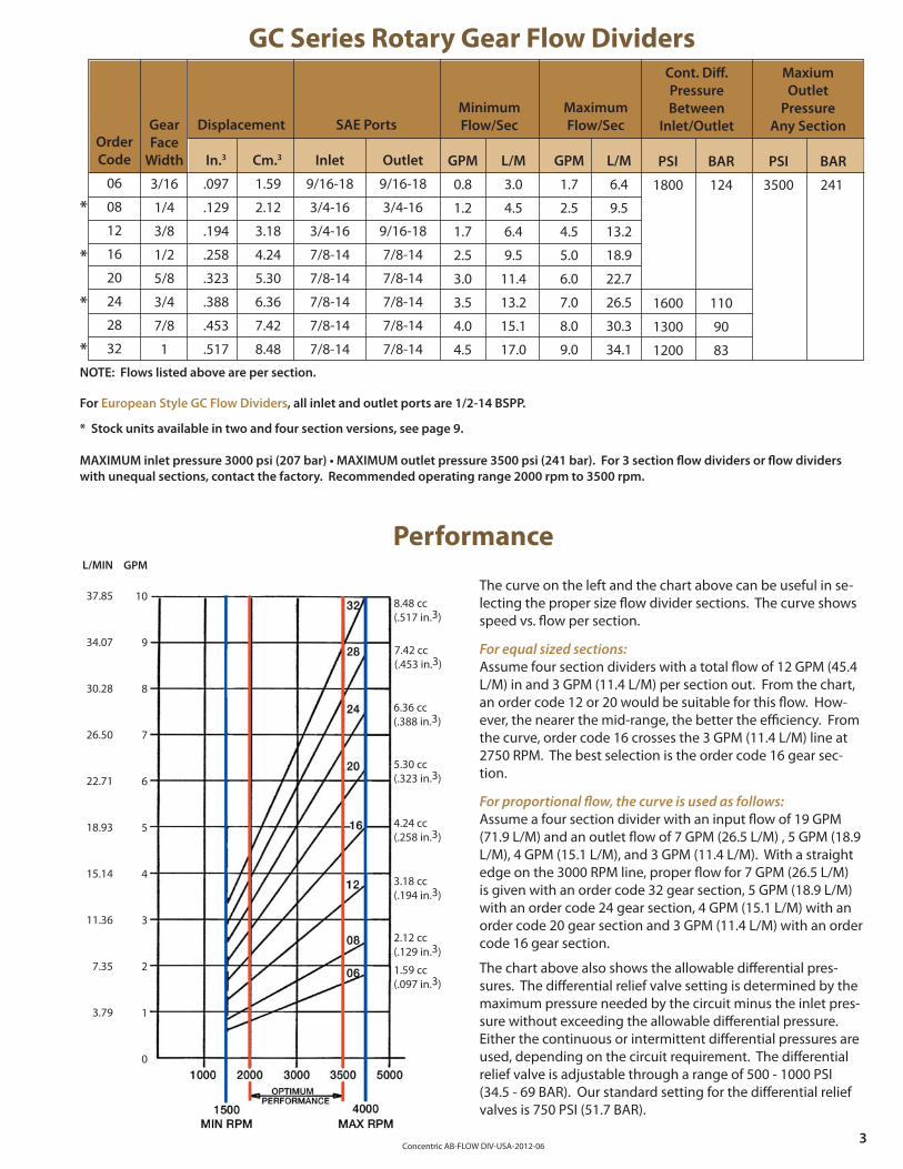
NOTE: Flows listed above are per section.
For European Style GC Flow Dividers, all inlet and outlet ports are 1/2-14 BSPP.
* Stock units available in two and four section versions, see page 9.
MAXIMUM inlet pressure 3000 psi (207 bar) • MAXIMUM outlet pressure 3500 psi (241 bar). For 3 section fl ow dividers or fl ow dividers
with unequal sections, contact the factory. Recommended operating range 2000 rpm to 3500 rpm.
*
*
*
*
Order
Code
06
08
12
16
20
24
28
32
Minimum Maximum
Flow/Sec Flow/Sec
GPM L/M GPM L/M
0.8 3.0 1.7 6.4
1.2 4.5 2.5 9.5
1.7 6.4 4.5 13.2
2.5 9.5 5.0 18.9
3.0 11.4 6.0 22.7
3.5 13.2 7.0 26.5
4.0 15.1 8.0 30.3
4.5 17.0 9.0 34.1
SAE Ports
Inlet Outlet
9/16-18 9/16-18
3/4-16 3/4-16
3/4-16 9/16-18
7/8-14 7/8-14
7/8-14 7/8-14
7/8-14 7/8-14
7/8-14 7/8-14
7/8-14 7/8-14
Displacement
In.3 Cm.3
.097 1.59
.129 2.12
.194 3.18
.258 4.24
.323 5.30
.388 6.36
.453 7.42
.517 8.48
Gear
Face
Width
3/16
1/4
3/8
1/2
5/8
3/4
7/8
1
The curve on the left and the chart above can be useful in se-lecting the proper size fl ow divider sections. The curve shows speed vs. fl ow per section.
For equal sized sections:Assume four section dividers with a total fl ow of 12 GPM (45.4 L/M) in and 3 GPM (11.4 L/M) per section out. From the chart, an order code 12 or 20 would be suitable for this fl ow. How-ever, the nearer the mid-range, the better the effi ciency. From the curve, order code 16 crosses the 3 GPM (11.4 L/M) line at 2750 RPM. The best selection is the order code 16 gear sec-tion.
For proportional fl ow, the curve is used as follows:Assume a four section divider with an input fl ow of 19 GPM (71.9 L/M) and an outlet fl ow of 7 GPM (26.5 L/M) , 5 GPM (18.9 L/M), 4 GPM (15.1 L/M), and 3 GPM (11.4 L/M). With a straight edge on the 3000 RPM line, proper fl ow for 7 GPM (26.5 L/M) is given with an order code 32 gear section, 5 GPM (18.9 L/M) with an order code 24 gear section, 4 GPM (15.1 L/M) with an order code 20 gear section and 3 GPM (11.4 L/M) with an order code 16 gear section.
The chart above also shows the allowable diff erential pres-sures. The diff erential relief valve setting is determined by the maximum pressure needed by the circuit minus the inlet pres-sure without exceeding the allowable diff erential pressure. Either the continuous or intermittent diff erential pressures are used, depending on the circuit requirement. The diff erential relief valve is adjustable through a range of 500 - 1000 PSI (34.5 - 69 BAR). Our standard setting for the diff erential relief valves is 750 PSI (51.7 BAR).
GPM
10
9
8
7
6
5
4
3
2
1
0
L/MIN
37.85
34.07
30.28
26.50
22.71
18.93
15.14
11.36
7.35
3.79
8.48 cc(.517 in.3)
7.42 cc(.453 in.3)
6.36 cc(.388 in.3)
5.30 cc(.323 in.3)
4.24 cc(.258 in.3)
3.18 cc(.194 in.3)
2.12 cc(.129 in.3)
1.59 cc(.097 in.3)
Performance
Concentric AB-FLOW DIV-USA-2012-064
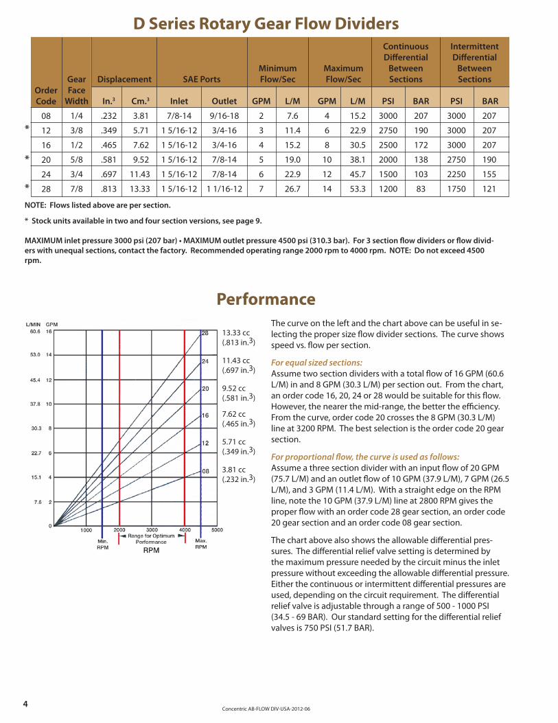
The curve on the left and the chart above can be useful in se-lecting the proper size fl ow divider sections. The curve shows speed vs. fl ow per section.
For equal sized sections:Assume two section dividers with a total fl ow of 16 GPM (60.6 L/M) in and 8 GPM (30.3 L/M) per section out. From the chart, an order code 16, 20, 24 or 28 would be suitable for this fl ow. However, the nearer the mid-range, the better the effi ciency. From the curve, order code 20 crosses the 8 GPM (30.3 L/M) line at 3200 RPM. The best selection is the order code 20 gear section.
For proportional fl ow, the curve is used as follows:Assume a three section divider with an input fl ow of 20 GPM (75.7 L/M) and an outlet fl ow of 10 GPM (37.9 L/M), 7 GPM (26.5 L/M), and 3 GPM (11.4 L/M). With a straight edge on the RPM line, note the 10 GPM (37.9 L/M) line at 2800 RPM gives the proper fl ow with an order code 28 gear section, an order code 20 gear section and an order code 08 gear section.
The chart above also shows the allowable diff erential pres-sures. The diff erential relief valve setting is determined by the maximum pressure needed by the circuit minus the inlet pressure without exceeding the allowable diff erential pressure. Either the continuous or intermittent diff erential pressures are used, depending on the circuit requirement. The diff erential relief valve is adjustable through a range of 500 - 1000 PSI (34.5 - 69 BAR). Our standard setting for the diff erential relief valves is 750 PSI (51.7 BAR).
D Series Rotary Gear Flow Dividers
Continuous
Diff erential
Between
Sections
PSI BAR
3000 207
2750 190
2500 172
2000 138
1500 103
1200 83
Intermittent
Diff erential
Between
Sections
PSI BAR
3000 207
3000 207
3000 207
2750 190
2250 155
1750 121
NOTE: Flows listed above are per section.
* Stock units available in two and four section versions, see page 9.
MAXIMUM inlet pressure 3000 psi (207 bar) • MAXIMUM outlet pressure 4500 psi (310.3 bar). For 3 section fl ow dividers or fl ow divid-
ers with unequal sections, contact the factory. Recommended operating range 2000 rpm to 4000 rpm. NOTE: Do not exceed 4500
rpm.
*
*
*
Order
Code
08
12
16
20
24
28
Minimum Maximum
Flow/Sec Flow/Sec
GPM L/M GPM L/M
2 7.6 4 15.2
3 11.4 6 22.9
4 15.2 8 30.5
5 19.0 10 38.1
6 22.9 12 45.7
7 26.7 14 53.3
SAE Ports
Inlet Outlet
7/8-14 9/16-18
1 5/16-12 3/4-16
1 5/16-12 3/4-16
1 5/16-12 7/8-14
1 5/16-12 7/8-14
1 5/16-12 1 1/16-12
Displacement
In.3 Cm.3
.232 3.81
.349 5.71
.465 7.62
.581 9.52
.697 11.43
.813 13.33
Gear
Face
Width
1/4
3/8
1/2
5/8
3/4
7/8
Performance
13.33 cc(.813 in.3)
11.43 cc(.697 in.3)
9.52 cc(.581 in.3)
7.62 cc(.465 in.3)
5.71 cc(.349 in.3)
3.81 cc(.232 in.3)
Concentric AB-FLOW DIV-USA-2012-065
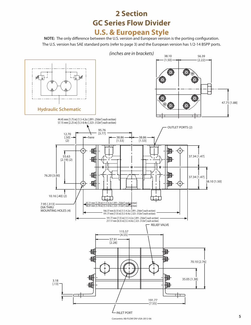
2 Section
GC Series Flow Divider
U.S. & European StyleNOTE: The only diff erence between the U.S. version and European version is the porting confi guration.
The U.S. version has SAE standard ports (refer to page 3) and the European version has 1/2-14 BSPP ports.
(inches are in brackets)
RELIEF VALVE
35.05 [1.38]
115.57[4.55]
INLET PORT
3.18[.13]
191.77[7.55]
70.10 [2.76]
57.91[2.28]
Hydraulic Schematic
56.39[2.22]
47.75 [1.88]
38.10[1.50]
38.86[1.53]
95.76[3.77]12.70
[.50](2)
76.20 [3.00]
10.16 [.40] (2)
37.34 [1.47]38.10 [1.50]
37.34 [1.47]
38.86[1.53]
OUTLET PORTS (2)
55.63[2.19] (2)
7.95 [.313]DIA THRUMOUNTING HOLES (4)
here
44.45 mm [1.75 in] (1.5-4.2cc [.091-.256in3] each section)57.15 mm [2.25 in] (5.3-8.4cc [.323-.512in3] each section)
83.31 mm [3.28 in] (1.5-4.2cc [.091-.256in3] each section)96.01 mm [3.78 in] (5.3-8.4cc [.323-.512in3] each section)
166.37 mm [6.55 in] (1.5-4.2cc [.091-.256in3] each section)191.77 mm [7.55 in] (5.3-8.4cc [.323-.512in3] each section)
191.77 mm [7.55 in] (1.5-4.2cc [.091-.256in3] each section)217.17 mm [8.55 in] (5.3-8.4cc [.323-.512in3] each section)
Concentric AB-FLOW DIV-USA-2012-066
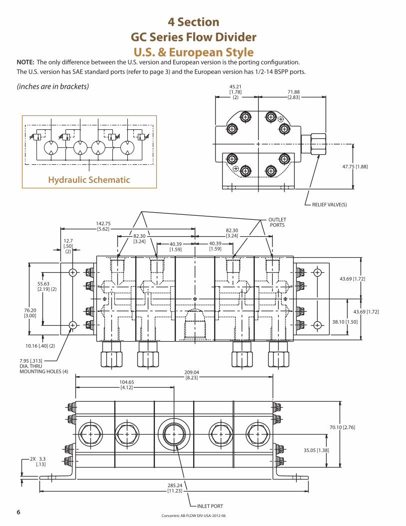
4 Section
GC Series Flow Divider
U.S. & European StyleNOTE: The only diff erence between the U.S. version and European version is the porting confi guration. The U.S. version has SAE standard ports (refer to page 3) and the European version has 1/2-14 BSPP ports.
(inches are in brackets)
Hydraulic Schematic
35.05 [1.38]
2X 3.3[.13]
285.24[11.23]
INLET PORT
70.10 [2.76]
104.65[4.12]
209.04[8.23]
71.88[2.83]
47.75 [1.88]
RELIEF VALVE(S)
45.21[1.78]
(2)
82.30[3.24]
142.75[5.62]
12.7[.50](2)
40.39[1.59]
40.39[1.59]
82.30[3.24]
OUTLETPORTS
43.69 [1.72]
43.69 [1.72]
38.10 [1.50]
10.16 [.40] (2)
7.95 [.313]DIA. THRUMOUNTING HOLES (4)
55.63[2.19] (2)
76.20[3.00]
Concentric AB-FLOW DIV-USA-2012-067
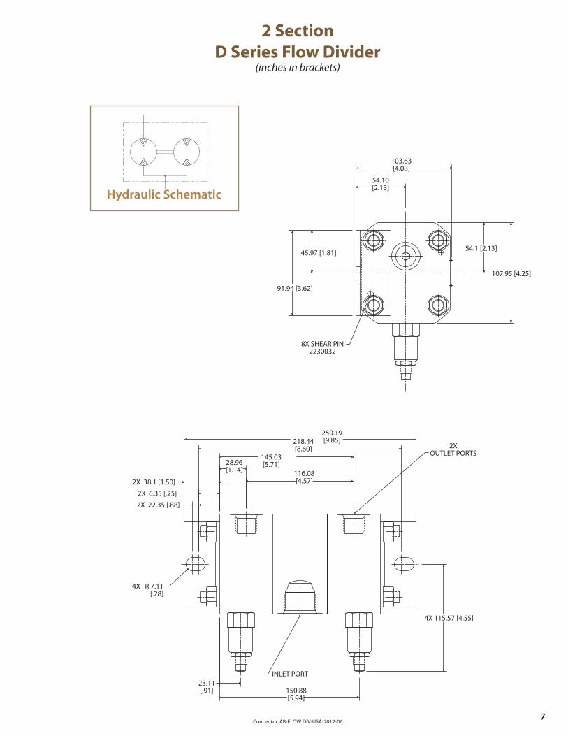
2 Section
D Series Flow Divider(inches in brackets)
Hydraulic Schematic
116.08[4.57]2X 38.1 [1.50]
4X R 7.11[.28]
2X 6.35 [.25]
2X 22.35 [.88]
150.88[5.94]
23.11[.91]
INLET PORT
4X 115.57 [4.55]
2XOUTLET PORTS
250.19[9.85]
145.03[5.71]28.96
[1.14]
218.44[8.60]
103.63[4.08]
45.97 [1.81]
91.94 [3.62]
54.1 [2.13]
107.95 [4.25]
8X SHEAR PIN2230032
54.10[2.13]
Concentric AB-FLOW DIV-USA-2012-068
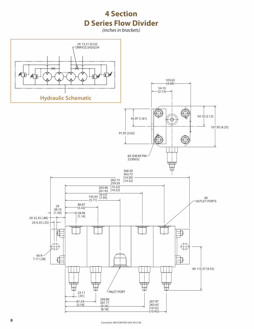
4 Section
D Series Flow Divider(inches in brackets)
8X SHEAR PIN2230032
54.10[2.13]
54.10 [2.13]45.97 [1.81]
103.63[4.08]
Hydraulic Schematic
2X 13.21 [0.52]ORIFICE/2420234
203.96201.93[8.03][7.95]
86.87[3.42]38.10
[1.50]
2X
2X 22.35 [.88]2X 6.35 [.25]
4X R7.11 [.28]
209.80207.77[8.26][8.18]
4XOUTLET PORTS
368.30363.73[14.50][14.32]262.13
259.59[10.32][10.22]
28.96[1.14]
23.11[.91]
81.03[3.19]
INLET PORT
267.97265.43[10.55][10.45]
4X 115.57 [4.55]
145.03[5.71]
91.95 [3.62]
107.95 [4.25]
Concentric AB-FLOW DIV-USA-2012-069
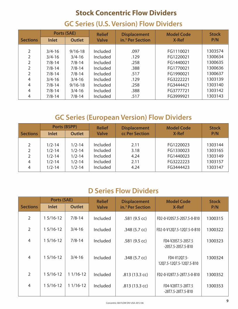
Stock Concentric Flow Dividers
Stock
P/N
1300315
1300322
1300323
1300324
1300352
1300353
Sections
2
2
4
4
2
4
Inlet
1 5/16-12
1 5/16-12
1 5/16-12
1 5/16-12
1 5/16-12
1 5/16-12
Ports (SAE)
Outlet
7/8-14
3/4-16
7/8-14
3/4-16
1 1/16-12
1 1/16-12
Relief
Valve
Included
Included
Included
Included
Included
Included
Displacement
in.3 Per Section
.581 (9.5 cc)
.348 (5.7 cc)
.581 (9.5 cc)
.348 (5.7 cc)
.813 (13.3 cc)
.813 (13.3 cc)
Model Code
X-Ref
FD2-0-V20S7.5-20S7.5-0-B10
FD2-0-V12Q7.5-12Q7.5-0-B10
FD4-V20S7.5-20S7.5-20S7.5-20S7.5-B10
FD4-V12Q7.5-12Q7.5-12Q7.5-12Q7.5-B10
FD2-0-V28T7.5-28T7.5-0-B10
FD4-V28T7.5-28T7.5-28T7.5-28T7.5-B10
D Series Flow Dividers
Sections
222224444
Inlet
3/4-163/4-167/8-147/8-147/8-143/4-167/8-147/8-147/8-14
Ports (SAE)
Outlet
9/16-183/4-167/8-147/8-147/8-143/4-16
9/16-183/4-167/8-14
Relief
Valve
Included IncludedIncludedIncludedIncludedIncludedIncludedIncludedIncluded
Displacement
in.3 Per Section
.097
.129
.258
.388
.517
.129
.258
.388
.517
Model Code
X-Ref
FG1110021 FG1220021FG1440021FG1770021FG1990021FG3222221FG3444421FG3777721FG3999921
Stock
P/N
1303574 13006341300635130063613006371303139130314013031421303143
GC Series (U.S. Version) Flow Dividers
Sections
22244
Inlet
1/2-141/2-141/2-141/2-141/2-14
Ports (BSPP)
Outlet
1/2-141/2-141/2-141/2-141/2-14
Relief
Valve
IncludedIncludedIncludedIncludedIncluded
Displacement
cc Per Section
2.113.184.242.114.24
Model Code
X-Ref
FG1220023FG1330023FG1440023FG3222223FG3444423
Stock
P/N
13031441303165130314913031571303147
GC Series (European Version) Flow Dividers
Concentric AB-FLOW DIV-USA-2012-0610
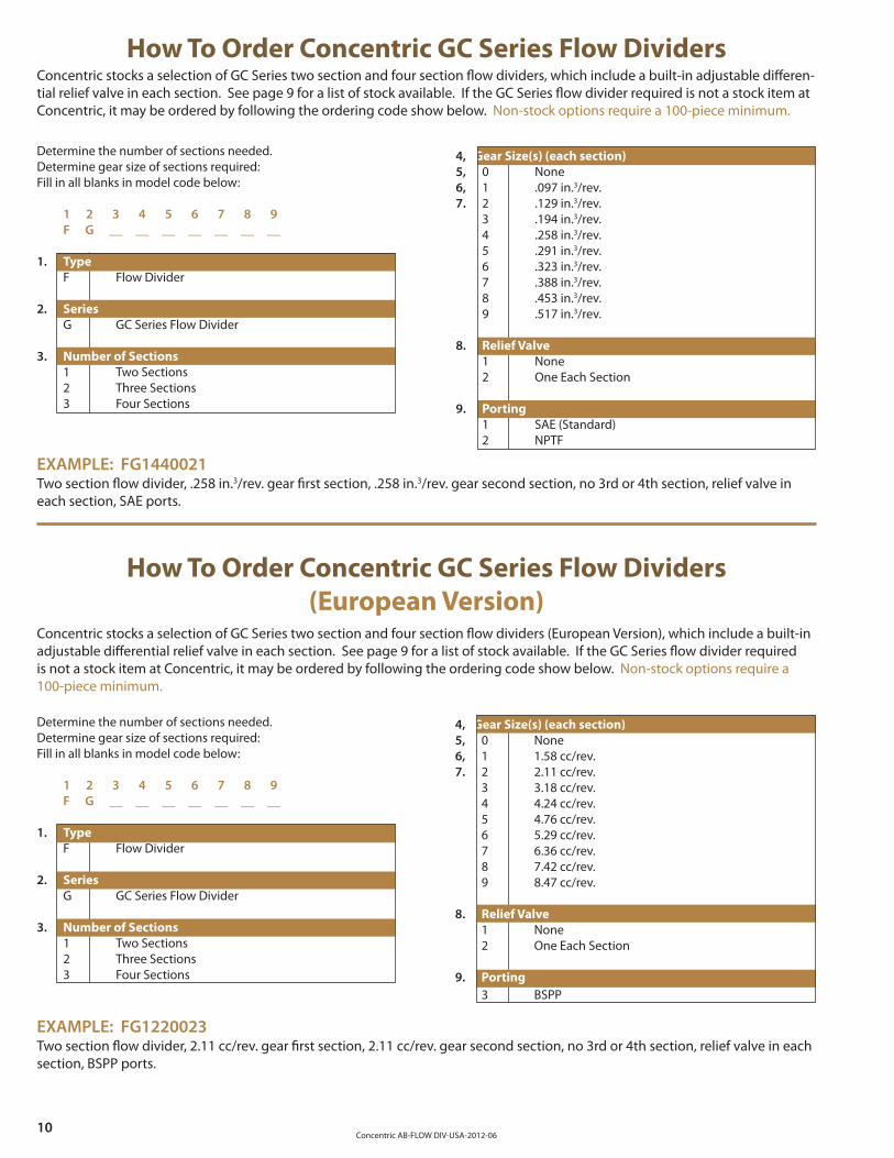
How To Order Concentric GC Series Flow DividersConcentric stocks a selection of GC Series two section and four section fl ow dividers, which include a built-in adjustable diff eren-tial relief valve in each section. See page 9 for a list of stock available. If the GC Series fl ow divider required is not a stock item at Concentric, it may be ordered by following the ordering code show below. Non-stock options require a 100-piece minimum.
EXAMPLE: FG1440021Two section fl ow divider, .258 in.3/rev. gear fi rst section, .258 in.3/rev. gear second section, no 3rd or 4th section, relief valve in each section, SAE ports.
4, Gear Size(s) (each section)
5, 0 None6, 1 .097 in.3/rev.7. 2 .129 in.3/rev. 3 .194 in.3/rev. 4 .258 in.3/rev. 5 .291 in.3/rev. 6 .323 in.3/rev. 7 .388 in.3/rev. 8 .453 in.3/rev. 9 .517 in.3/rev.
8. Relief Valve
1 None 2 One Each Section
9. Porting
1 SAE (Standard) 2 NPTF
Determine the number of sections needed. Determine gear size of sections required: Fill in all blanks in model code below:
1 2 3 4 5 6 7 8 9
F G __ __ __ __ __ __ __
1. Type
F Flow Divider
2. Series
G GC Series Flow Divider
3. Number of Sections
1 Two Sections 2 Three Sections 3 Four Sections
How To Order Concentric GC Series Flow Dividers
(European Version)Concentric stocks a selection of GC Series two section and four section fl ow dividers (European Version), which include a built-in adjustable diff erential relief valve in each section. See page 9 for a list of stock available. If the GC Series fl ow divider required is not a stock item at Concentric, it may be ordered by following the ordering code show below. Non-stock options require a 100-piece minimum.
EXAMPLE: FG1220023Two section fl ow divider, 2.11 cc/rev. gear fi rst section, 2.11 cc/rev. gear second section, no 3rd or 4th section, relief valve in each section, BSPP ports.
4, Gear Size(s) (each section)
5, 0 None6, 1 1.58 cc/rev.7. 2 2.11 cc/rev. 3 3.18 cc/rev. 4 4.24 cc/rev. 5 4.76 cc/rev. 6 5.29 cc/rev. 7 6.36 cc/rev. 8 7.42 cc/rev. 9 8.47 cc/rev.
8. Relief Valve
1 None 2 One Each Section
9. Porting
3 BSPP
Determine the number of sections needed. Determine gear size of sections required: Fill in all blanks in model code below:
1 2 3 4 5 6 7 8 9
F G __ __ __ __ __ __ __
1. Type
F Flow Divider
2. Series
G GC Series Flow Divider
3. Number of Sections
1 Two Sections 2 Three Sections 3 Four Sections
Concentric AB-FLOW DIV-USA-2012-0611
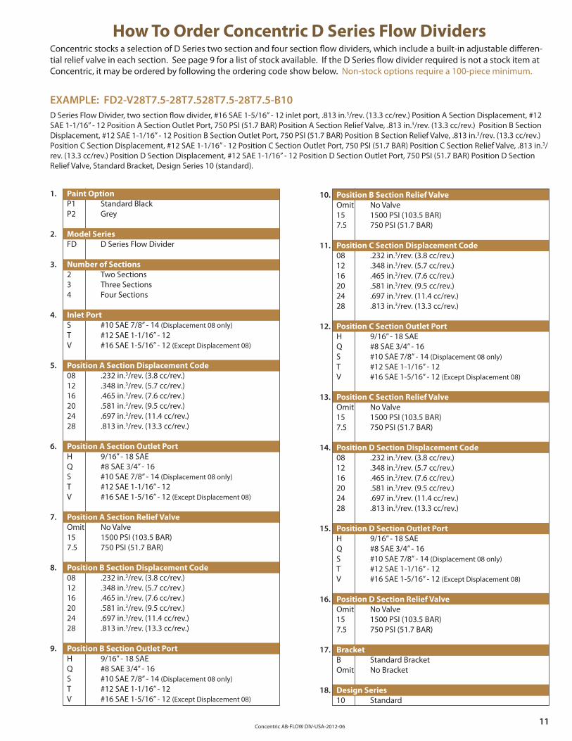
How To Order Concentric D Series Flow DividersConcentric stocks a selection of D Series two section and four section fl ow dividers, which include a built-in adjustable diff eren-tial relief valve in each section. See page 9 for a list of stock available. If the D Series fl ow divider required is not a stock item at Concentric, it may be ordered by following the ordering code show below. Non-stock options require a 100-piece minimum.
EXAMPLE: FD2-V28T7.5-28T7.528T7.5-28T7.5-B10
D Series Flow Divider, two section fl ow divider, #16 SAE 1-5/16” - 12 inlet port, .813 in.3/rev. (13.3 cc/rev.) Position A Section Displacement, #12 SAE 1-1/16” - 12 Position A Section Outlet Port, 750 PSI (51.7 BAR) Position A Section Relief Valve, .813 in.3/rev. (13.3 cc/rev.) Position B Section Displacement, #12 SAE 1-1/16” - 12 Position B Section Outlet Port, 750 PSI (51.7 BAR) Position B Section Relief Valve, .813 in.3/rev. (13.3 cc/rev.) Position C Section Displacement, #12 SAE 1-1/16” - 12 Position C Section Outlet Port, 750 PSI (51.7 BAR) Position C Section Relief Valve, .813 in.3/rev. (13.3 cc/rev.) Position D Section Displacement, #12 SAE 1-1/16” - 12 Position D Section Outlet Port, 750 PSI (51.7 BAR) Position D Section Relief Valve, Standard Bracket, Design Series 10 (standard).
1. Paint Option
P1 Standard Black P2 Grey
2. Model Series
FD D Series Flow Divider
3. Number of Sections
2 Two Sections 3 Three Sections 4 Four Sections
4. Inlet Port
S #10 SAE 7/8” - 14 (Displacement 08 only) T #12 SAE 1-1/16” - 12 V #16 SAE 1-5/16” - 12 (Except Displacement 08) 5. Position A Section Displacement Code
08 .232 in.3/rev. (3.8 cc/rev.) 12 .348 in.3/rev. (5.7 cc/rev.) 16 .465 in.3/rev. (7.6 cc/rev.) 20 .581 in.3/rev. (9.5 cc/rev.) 24 .697 in.3/rev. (11.4 cc/rev.) 28 .813 in.3/rev. (13.3 cc/rev.)
6. Position A Section Outlet Port
H 9/16” - 18 SAE Q #8 SAE 3/4” - 16 S #10 SAE 7/8” - 14 (Displacement 08 only) T #12 SAE 1-1/16” - 12 V #16 SAE 1-5/16” - 12 (Except Displacement 08)
7. Position A Section Relief Valve
Omit No Valve 15 1500 PSI (103.5 BAR) 7.5 750 PSI (51.7 BAR)
8. Position B Section Displacement Code
08 .232 in.3/rev. (3.8 cc/rev.) 12 .348 in.3/rev. (5.7 cc/rev.) 16 .465 in.3/rev. (7.6 cc/rev.) 20 .581 in.3/rev. (9.5 cc/rev.) 24 .697 in.3/rev. (11.4 cc/rev.) 28 .813 in.3/rev. (13.3 cc/rev.)
9. Position B Section Outlet Port
H 9/16” - 18 SAE Q #8 SAE 3/4” - 16 S #10 SAE 7/8” - 14 (Displacement 08 only) T #12 SAE 1-1/16” - 12 V #16 SAE 1-5/16” - 12 (Except Displacement 08)
10. Position B Section Relief Valve
Omit No Valve 15 1500 PSI (103.5 BAR) 7.5 750 PSI (51.7 BAR)
11. Position C Section Displacement Code
08 .232 in.3/rev. (3.8 cc/rev.) 12 .348 in.3/rev. (5.7 cc/rev.) 16 .465 in.3/rev. (7.6 cc/rev.) 20 .581 in.3/rev. (9.5 cc/rev.) 24 .697 in.3/rev. (11.4 cc/rev.) 28 .813 in.3/rev. (13.3 cc/rev.)
12. Position C Section Outlet Port
H 9/16” - 18 SAE Q #8 SAE 3/4” - 16 S #10 SAE 7/8” - 14 (Displacement 08 only) T #12 SAE 1-1/16” - 12 V #16 SAE 1-5/16” - 12 (Except Displacement 08)
13. Position C Section Relief Valve
Omit No Valve 15 1500 PSI (103.5 BAR) 7.5 750 PSI (51.7 BAR)
14. Position D Section Displacement Code
08 .232 in.3/rev. (3.8 cc/rev.) 12 .348 in.3/rev. (5.7 cc/rev.) 16 .465 in.3/rev. (7.6 cc/rev.) 20 .581 in.3/rev. (9.5 cc/rev.) 24 .697 in.3/rev. (11.4 cc/rev.) 28 .813 in.3/rev. (13.3 cc/rev.)
15. Position D Section Outlet Port
H 9/16” - 18 SAE Q #8 SAE 3/4” - 16 S #10 SAE 7/8” - 14 (Displacement 08 only) T #12 SAE 1-1/16” - 12 V #16 SAE 1-5/16” - 12 (Except Displacement 08)
16. Position D Section Relief Valve
Omit No Valve 15 1500 PSI (103.5 BAR) 7.5 750 PSI (51.7 BAR)
17. Bracket
B Standard Bracket Omit No Bracket
18. Design Series
10 Standard
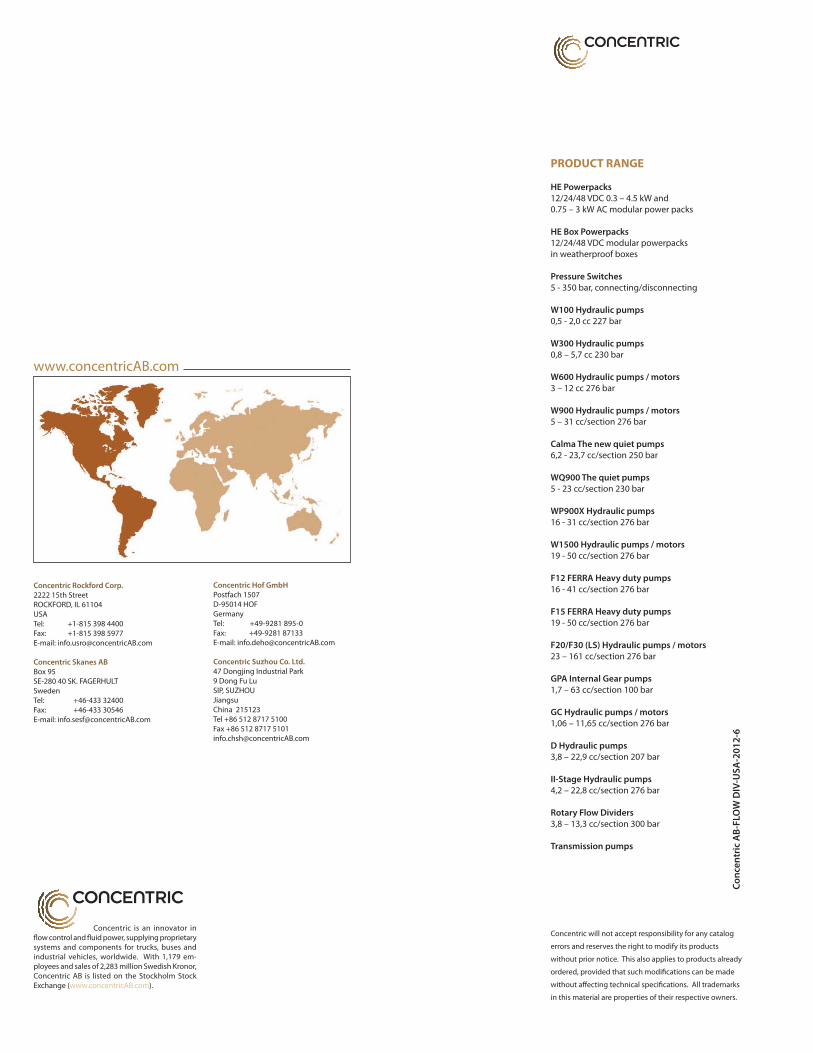
Concentric is an innovator in fl ow control and fl uid power, supplying proprietary systems and components for trucks, buses and industrial vehicles, worldwide. With 1,179 em-ployees and sales of 2,283 million Swedish Kronor, Concentric AB is listed on the Stockholm Stock Exchange (www.concentricAB.com).
www.concentricAB.com
Concentric Rockford Corp.
2222 15th Street ROCKFORD, IL 61104 USA Tel: +1-815 398 4400 Fax: +1-815 398 5977E-mail: [email protected]
Concentric Skanes AB
Box 95 SE-280 40 SK. FAGERHULT Sweden Tel: +46-433 32400 Fax: +46-433 30546E-mail: [email protected]
PRODUCT RANGE
HE Powerpacks
12/24/48 VDC 0.3 – 4.5 kW and 0.75 – 3 kW AC modular power packs
HE Box Powerpacks
12/24/48 VDC modular powerpacks in weatherproof boxes
Pressure Switches
5 - 350 bar, connecting/disconnecting
W100 Hydraulic pumps
0,5 - 2,0 cc 227 bar
W300 Hydraulic pumps
0,8 – 5,7 cc 230 bar
W600 Hydraulic pumps / motors
3 – 12 cc 276 bar
W900 Hydraulic pumps / motors
5 – 31 cc/section 276 bar
Calma The new quiet pumps
6,2 - 23,7 cc/section 250 bar
WQ900 The quiet pumps
5 - 23 cc/section 230 bar
WP900X Hydraulic pumps
16 - 31 cc/section 276 bar
W1500 Hydraulic pumps / motors
19 - 50 cc/section 276 bar
F12 FERRA Heavy duty pumps
16 - 41 cc/section 276 bar
F15 FERRA Heavy duty pumps
19 - 50 cc/section 276 bar
F20/F30 (LS) Hydraulic pumps / motors
23 – 161 cc/section 276 bar
GPA Internal Gear pumps
1,7 – 63 cc/section 100 bar
GC Hydraulic pumps / motors
1,06 – 11,65 cc/section 276 bar
D Hydraulic pumps
3,8 – 22,9 cc/section 207 bar
II-Stage Hydraulic pumps
4,2 – 22,8 cc/section 276 bar
Rotary Flow Dividers
3,8 – 13,3 cc/section 300 bar
Transmission pumps
Co
nce
ntr
ic A
B-F
LO
W D
IV-U
SA
-20
12
-6
Concentric will not accept responsibility for any catalog
errors and reserves the right to modify its products
without prior notice. This also applies to products already
ordered, provided that such modifi cations can be made
without aff ecting technical specifi cations. All trademarks
in this material are properties of their respective owners.
Concentric Hof GmbH
Postfach 1507 D-95014 HOFGermany Tel: +49-9281 895-0 Fax: +49-9281 87133E-mail: [email protected]
Concentric Suzhou Co. Ltd.
47 Dongjing Industrial Park9 Dong Fu LuSIP, SUZHOUJiangsuChina 215123Tel +86 512 8717 5100Fax +86 512 8717 [email protected]