Embed Size (px)
Citation preview
14-02-2017 IM312A
FLOW CONTROL TRAINER
(PCT version)
(With Ethernet communication)
Instruction manual
Contents
1 Description
2 Specifications
3 Packing slip
4 Installation requirements
5 Installation commissioning
6 Troubleshooting
7 Components used
8 Warranty
9 Experiments
Product Code 312A
Apex Innovations
14-02-2017 2 IM312A
Documents to be referred
Following table lists various documents available in PCTSoft CD which needs to be referred while
working with the product.
File name Document description
Im311A.pdf Product Instruction manual & Experiments
Theory Process Control.pdf Describes theoretical aspects of process control study
Components.pdf Additional details of the components used
Apex Innovations
14-02-2017 3 IM312A
Description
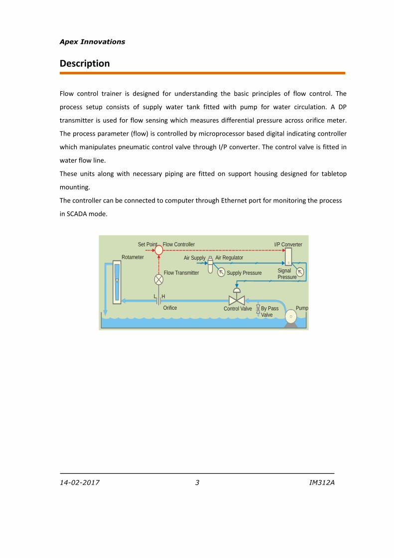
Flow control trainer is designed for understanding the basic principles of flow control. The
process setup consists of supply water tank fitted with pump for water circulation. A DP
transmitter is used for flow sensing which measures differential pressure across orifice meter.
The process parameter (flow) is controlled by microprocessor based digital indicating controller
which manipulates pneumatic control valve through I/P converter. The control valve is fitted in
water flow line.
These units along with necessary piping are fitted on support housing designed for tabletop
mounting.
The controller can be connected to computer through Ethernet port for monitoring the process
in SCADA mode.
Supply Pressure Signal Pressure
Air Regulator
I/P Converter
Control Valve
Set Point
Flow Transmitter
Rotameter
Orifice By Pass Valve
Pump
Flow Controller
HL
Air Supply
Apex Innovations
14-02-2017 4 IM312A
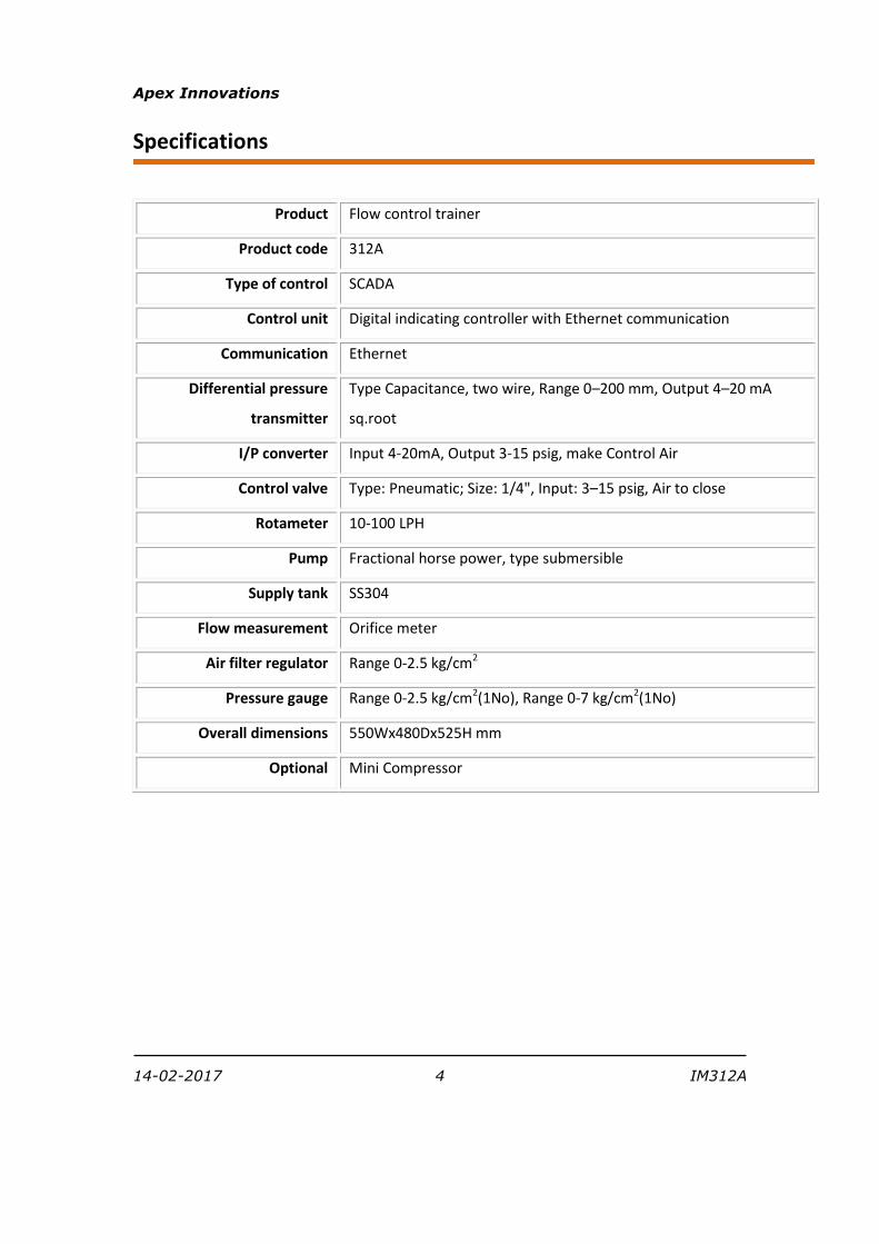
Specifications
Product Flow control trainer
Product code 312A
Type of control SCADA
Control unit Digital indicating controller with Ethernet communication
Communication Ethernet
Differential pressure
transmitter
Type Capacitance, two wire, Range 0–200 mm, Output 4–20 mA
sq.root
I/P converter Input 4-20mA, Output 3-15 psig, make Control Air
Control valve Type: Pneumatic; Size: 1/4", Input: 3–15 psig, Air to close
Rotameter 10-100 LPH
Pump Fractional horse power, type submersible
Supply tank SS304
Flow measurement Orifice meter
Air filter regulator Range 0-2.5 kg/cm2
Pressure gauge Range 0-2.5 kg/cm2(1No), Range 0-7 kg/cm2(1No)
Overall dimensions 550Wx480Dx525H mm
Optional Mini Compressor
Apex Innovations
14-02-2017 5 IM312A
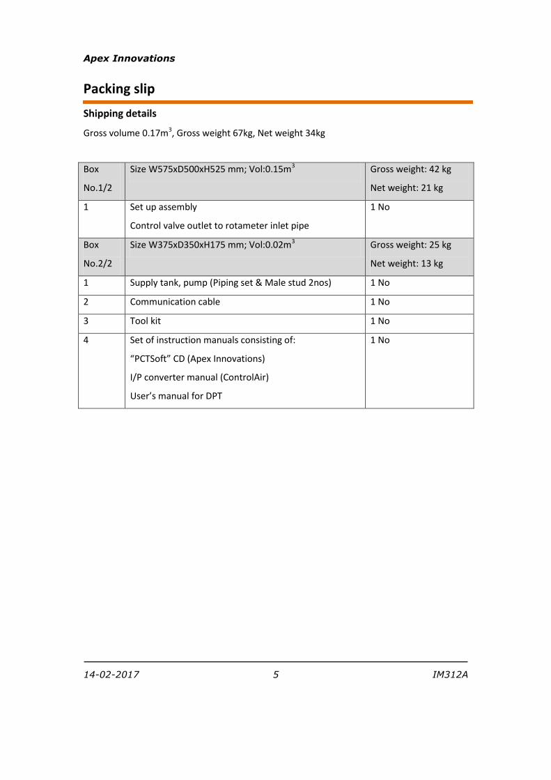
Packing slip
Shipping details
Gross volume 0.17m3, Gross weight 67kg, Net weight 34kg
Box
No.1/2
Size W575xD500xH525 mm; Vol:0.15m3 Gross weight: 42 kg
Net weight: 21 kg
1 Set up assembly
Control valve outlet to rotameter inlet pipe
1 No
Box
No.2/2
Size W375xD350xH175 mm; Vol:0.02m3 Gross weight: 25 kg
Net weight: 13 kg
1 Supply tank, pump (Piping set & Male stud 2nos) 1 No
2 Communication cable 1 No
3 Tool kit 1 No
4 Set of instruction manuals consisting of:
“PCTSoft” CD (Apex Innovations)
I/P converter manual (ControlAir)
User’s manual for DPT
1 No
Apex Innovations
14-02-2017 6 IM312A
Installation requirements
Electric supply
Provide 230 VAC single phase electric supply with proper earthing. (Neutral – Earth voltage less
than 5 VAC)
5A, three pin socket with switch (1 No.)
Water supply
Distilled water @10 liters
Air supply
Clean, oil and moisture free air, pressure 2 Bar, consumption 50 LPH
Computer
Standard configuration
Support table
Size: 800Wx800Dx750H in mm

14-02-2017 7 IM312A
Installation commissioning
Installation
Front view:
Back view:
14-02-2017 8 IM312A
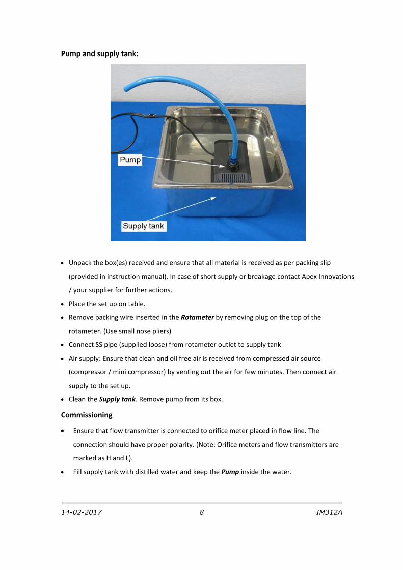
Pump and supply tank:
Unpack the box(es) received and ensure that all material is received as per packing slip
(provided in instruction manual). In case of short supply or breakage contact Apex Innovations
/ your supplier for further actions.
Place the set up on table.
Remove packing wire inserted in the Rotameter by removing plug on the top of the
rotameter. (Use small nose pliers)
Connect SS pipe (supplied loose) from rotameter outlet to supply tank
Air supply: Ensure that clean and oil free air is received from compressed air source
(compressor / mini compressor) by venting out the air for few minutes. Then connect air
supply to the set up.
Clean the Supply tank. Remove pump from its box.
Commissioning
Ensure that flow transmitter is connected to orifice meter placed in flow line. The
connection should have proper polarity. (Note: Orifice meters and flow transmitters are
marked as H and L).
Fill supply tank with distilled water and keep the Pump inside the water.
14-02-2017 9 IM312A
Keep the setup over the tray. Take the pump cable and pump outlet tube to the top side
through the hole on the base plate. Connect the cable to the pump switch and connect the
pump outlet tube to the inlet of control valve.
Return the bypass line back to SS tray through the hole provided on the base plate.
Switch on electric supply. Switch on Mains.
Switch on the pump and ensure that flow through rotameter is above 100 LPH.
Confirm that flow signal reading is displayed at controller. (For 100 LPH flow the reading
should be @100%. If not, remove air from the pressure signal connections of Flow
transmitter by loosening vent plugs provided on it).
Ensure that Air regulator is fully open by rotating anticlockwise. Switch on the compressed
air source and adjust the Air regulator to set supply air pressure at @ 25 psig.
Set the controller to manual mode by pressing the A/M key.
Increase output of controller from 0 to 100% in steps of 25%. Check the pressure on
pressure gauge at the output of I/P converter is varying from 3-15 psig and ensure that
Control valve operates from full open to fully close position.
Switch on the computer and install “MCRInstaller “ provided on PCTSoft CD
Copy the file “Apex_Process_Trainers “ at any drive/ folder.
Create the desktop icon for the “Apex _Process_Trainers” for further use.
Set computer IP address as 192.168.1.2
Execute the software and ensure correct signals are displayed on computer.
NOTE: For longer shut down, remove water from the supply tank and clean it.
14-02-2017 10 IM312A
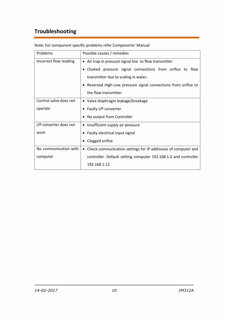
Troubleshooting
Note: For component specific problems refer Components’ Manual
Problems Possible causes / remedies
Incorrect flow reading Air trap in pressure signal line to flow transmitter
Choked pressure signal connections from orifice to flow
transmitter due to scaling in water.
Reversed High-Low pressure signal connections from orifice to
the flow transmitter
Control valve does not
operate
Valve diaphragm leakage/breakage
Faulty I/P converter
No output from Controller
I/P converter does not
work
Insufficient supply air pressure
Faulty electrical input signal
Clogged orifice
No communication with
computer
Check communication settings for IP addresses of computer and
controller. Default setting computer 192.168.1.2 and controller
192.168.1.12
14-02-2017 11 IM312A
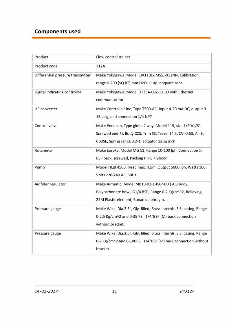
Components used
Product Flow control trainer
Product code 312A
Differential pressure transmitter Make Yokogawa, Model EJA110E-JMS5J-912NN, Calibration
range 0-200 (SQ RT) mm H2O, Output square root
Digital indicating controller Make Yokogawa, Model UT35A-002-11-00 with Ethernet
communication
I/P converter Make Control air inc, Type T500-AC, Input 4-20 mA DC, output 3-
15 psig, end connection 1/4 NPT
Control valve Make Pneucon, Type globe 2 way, Model 119, size 1/2"x1/8",
Screwed end(F), Body CCS, Trim SS, Travel 14.3, CV=0.63, Air to
CLOSE, Spring range 0.2-1, actuator 12 sq inch.
Rotameter Make Eureka, Model MG 11, Range 10-100 lph, Connection ¼”
BSP back, screwed, Packing PTFE + Silicon
Pump Model HQB 4500, Head max. 4.5m, Output 5000 lph, Watts 100,
Volts 220-240 AC, 50Hz.
Air filter regulator Make Airmatic, Model MB10-02-1-PAP-PD ( Alu body,
Polycarbonate bowl, G1/4 BSP, Range 0-2 Kg/cm^2, Relieving,
25M Plastic element, Bunan diaphragm.
Pressure gauge Make Wika, Dia.2.5", Gly. filled, Brass internls, S.S. casing, Range
0-2.5 Kg/cm^2 and 0-35 PSI, 1/4"BSP (M) back connection
without bracket.
Pressure gauge Make Wika, Dia.2.5", Gly. filled, Brass internls, S.S. casing, Range
0-7 Kg/cm^2 and 0-100PSI, 1/4"BSP (M) back connection without
bracket.
14-02-2017 12 IM312A
Warranty
This product is warranted for a period of 12 months from the date of supply against
manufacturing defects. You shall inform us in writing any defect in the system noticed during the
warranty period. On receipt of your written notice, Apex at its option either repairs or replaces
the product if proved to be defective as stated above. You shall not return any part of the
system to us before receiving our confirmation to this effect.
The foregoing warranty shall not apply to defects resulting from:
Buyer/ User shall not have subjected the system to unauthorized alterations/ additions/
modifications.
Unauthorized use of external software/ interfacing.
Unauthorized maintenance by third party not authorized by Apex.
Improper site utilities and/or maintenance.
We do not take any responsibility for accidental injuries caused while working with the set up.
Apex Innovations Pvt. Ltd.
E9/1, MIDC, Kupwad, Sangli-416436 (Maharashtra) India
Telefax:0233-2644098, 2644398
Email: support @apexinnovations.co.in Web: www.apexinnovations.co.in
14-02-2017 13 IM312A
Experiments The experiment nos 1 thr 6 are to get feel of the process and PID settings.
1 Study of open loop response (Manual control)
Procedure
Switch on electric supply. Switch on Mains.
Switch on the pump and adjust the bypass valve to set rotameter flow at 100 LPH.
Switch on the compressed air source and adjust the air regulator to set supply air pressure at
@ 2 kg/cm^2
Switch on the computer.
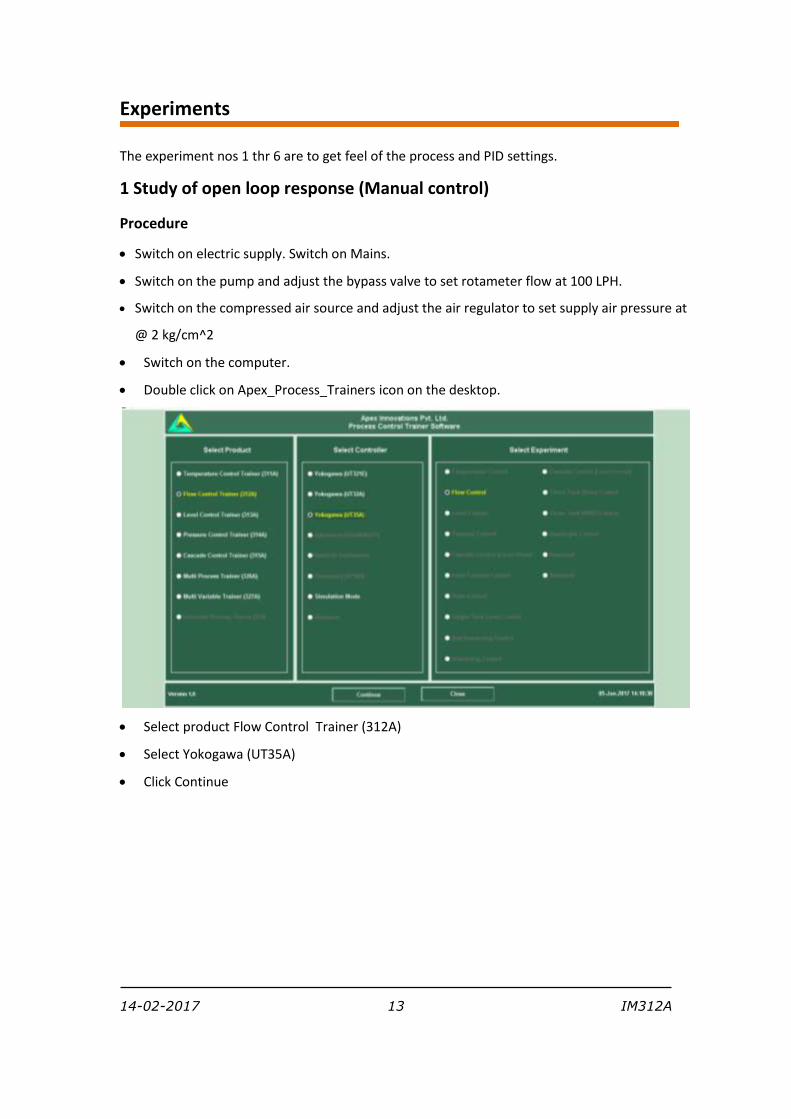
Double click on Apex_Process_Trainers icon on the desktop.
Select product Flow Control Trainer (312A)
Select Yokogawa (UT35A)
Click Continue
14-02-2017 14 IM312A
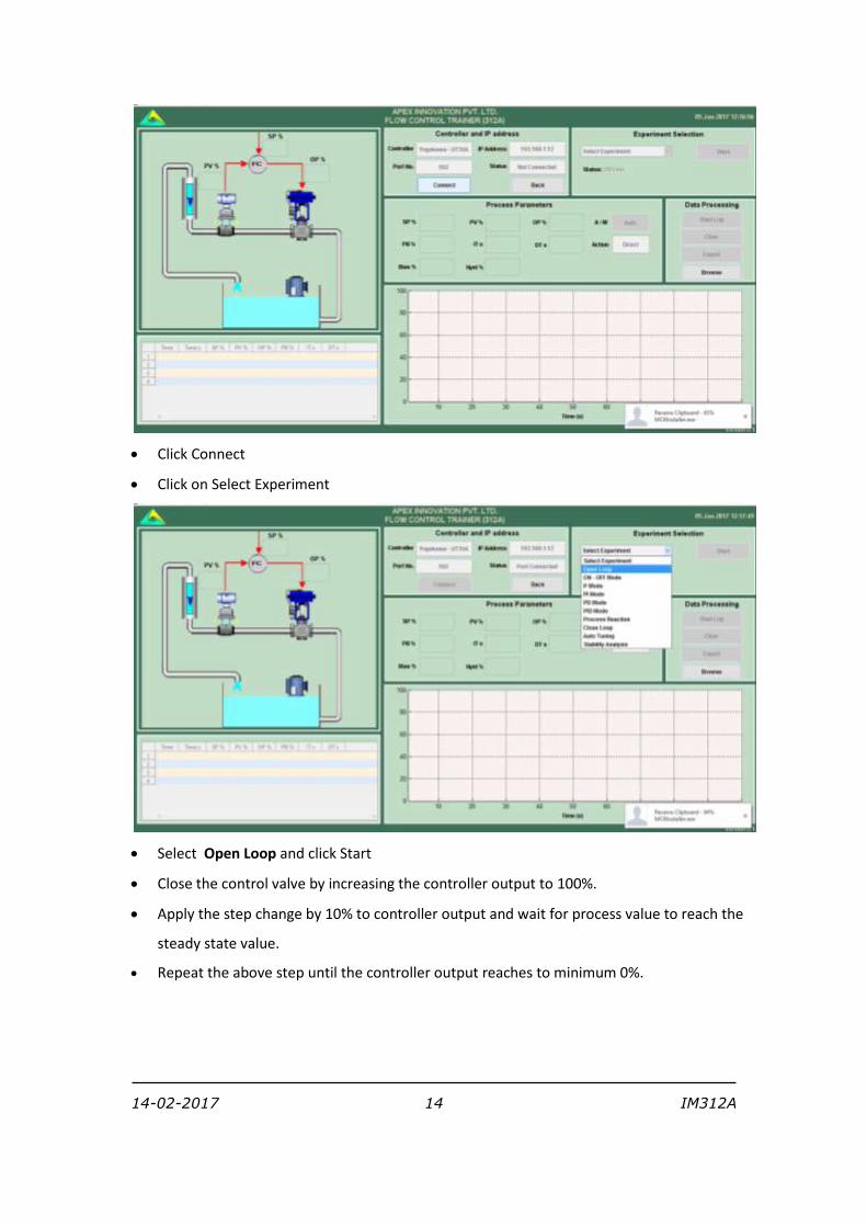
Click Connect
Click on Select Experiment
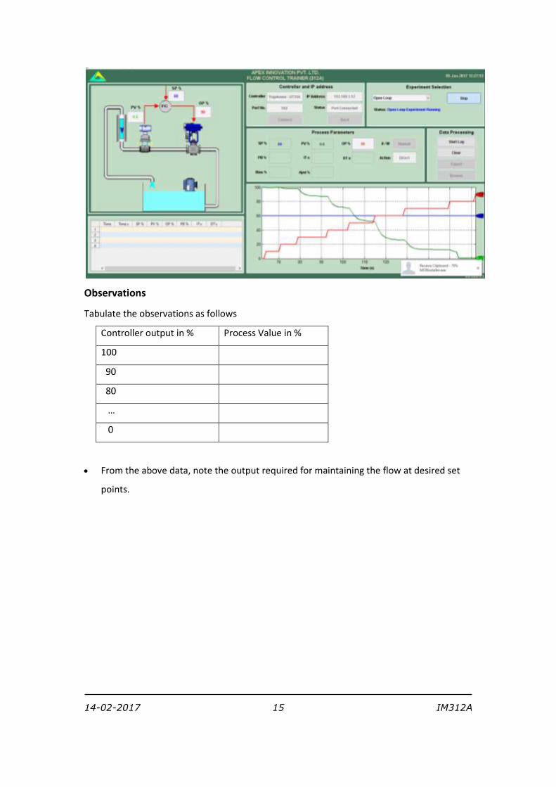
Select Open Loop and click Start
Close the control valve by increasing the controller output to 100%.
Apply the step change by 10% to controller output and wait for process value to reach the
steady state value.
Repeat the above step until the controller output reaches to minimum 0%.
14-02-2017 15 IM312A
Observations
Tabulate the observations as follows
Controller output in % Process Value in %
100
90
80
…
0
From the above data, note the output required for maintaining the flow at desired set
points.
14-02-2017 16 IM312A
2 Study of on/off controller
Switch on electric supply. Switch on Mains.
Switch on the pump and adjust the bypass valve to set rotameter flow at 100 LPH.
Switch on the compressed air source and adjust the air regulator to set supply air pressure at
@ 2 kg/cm^2
Switch on the computer.
Double click on Apex_Process_Trainers icon on the desktop.
Select product Flow Control Trainer (312A)
Select Yokogawa (UT35A)
Click Continue
Click Connect
Click on Select Experiment
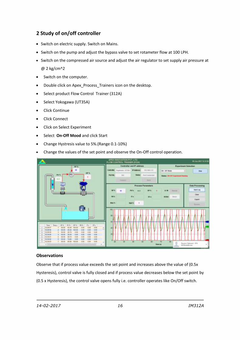
Select On-Off Mood and click Start
Change Hystresis value to 5%.(Range 0.1-10%)
Change the values of the set point and observe the On-Off control operation.
Observations
Observe that if process value exceeds the set point and increases above the value of (0.5x
Hysteresis), control valve is fully closed and if process value decreases below the set point by
(0.5 x Hysteresis), the control valve opens fully i.e. controller operates like On/Off switch.
14-02-2017 17 IM312A
3 Study of proportional controller
Switch on electric supply. Switch on Mains.
Switch on the pump and adjust the bypass valve to set rotameter flow at 100 LPH.
Switch on the compressed air source and adjust the air regulator to set supply air pressure at
@ 2 kg/cm^2
Switch on the computer.
Double click on Apex_Process_Trainers icon on the desktop.
Select product Flow Control Trainer (312A)
Select Yokogawa (UT35A)
Click Continue
Click Connect
Click on Select Experiment
Select P Mood and click Start
Adjust the process value by switching the controller to manual mode to a particular flow (say
50 %) on the screen and apply output of the controller as bias value. Change the
proportional band to 100%.
Switch the controller to auto mode.
Apply step change of 10% to set point.
Switch the controller to manual mode. Decrease proportional band to half of the previous
value. With each decrease, obtain a new response of the step change. Ensure that the set
point changes are around the same operating point (Say 50%).
Using trail and error approach find a value of proportional band so that the response to a
step change has at most one overshoot and one undershoot.
Set the controller to the settings obtained in the above step and wait for the system to reach
at steady state.
14-02-2017 18 IM312A
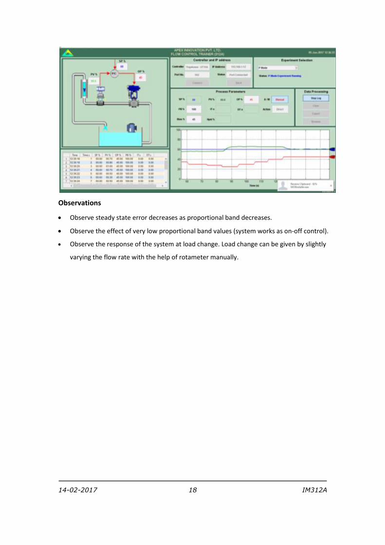
Observations
Observe steady state error decreases as proportional band decreases.
Observe the effect of very low proportional band values (system works as on-off control).
Observe the response of the system at load change. Load change can be given by slightly
varying the flow rate with the help of rotameter manually.
14-02-2017 19 IM312A
4 Study of proportional integral controller
Switch on electric supply. Switch on Mains.
Switch on the pump and adjust the bypass valve to set rotameter flow at 100 LPH.
Switch on the compressed air source and adjust the air regulator to set supply air pressure at
@ 2 kg/cm^2
Switch on the computer.
Double click on Apex_Process_Trainers icon on the desktop.
Select product Flow Control Trainer (312A)
Select Yokogawa (UT35A)
Click Continue
Click Connect
Click on Select Experiment
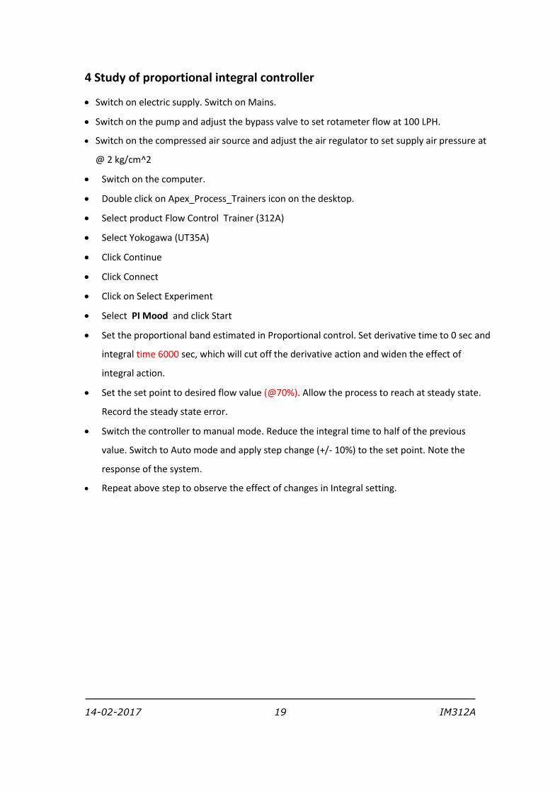
Select PI Mood and click Start
Set the proportional band estimated in Proportional control. Set derivative time to 0 sec and
integral time 6000 sec, which will cut off the derivative action and widen the effect of
integral action.
Set the set point to desired flow value (@70%). Allow the process to reach at steady state.
Record the steady state error.
Switch the controller to manual mode. Reduce the integral time to half of the previous
value. Switch to Auto mode and apply step change (+/- 10%) to the set point. Note the
response of the system.
Repeat above step to observe the effect of changes in Integral setting.
14-02-2017 20 IM312A
Observations
Observe the effect of reducing integral time on offset and on the response of the process.
14-02-2017 21 IM312A
5 Study of proportional derivative controller
Switch on electric supply. Switch on Mains.
Switch on the pump and adjust the bypass valve to set rotameter flow at 100 LPH.
Switch on the compressed air source and adjust the air regulator to set supply air pressure at
@ 2 kg/cm^2
Switch on the computer.
Double click on Apex_Process_Trainers icon on the desktop.
Select product Flow Control Trainer (312A)
Select Yokogawa (UT35A)
Click Continue
Click Connect
Click on Select Experiment
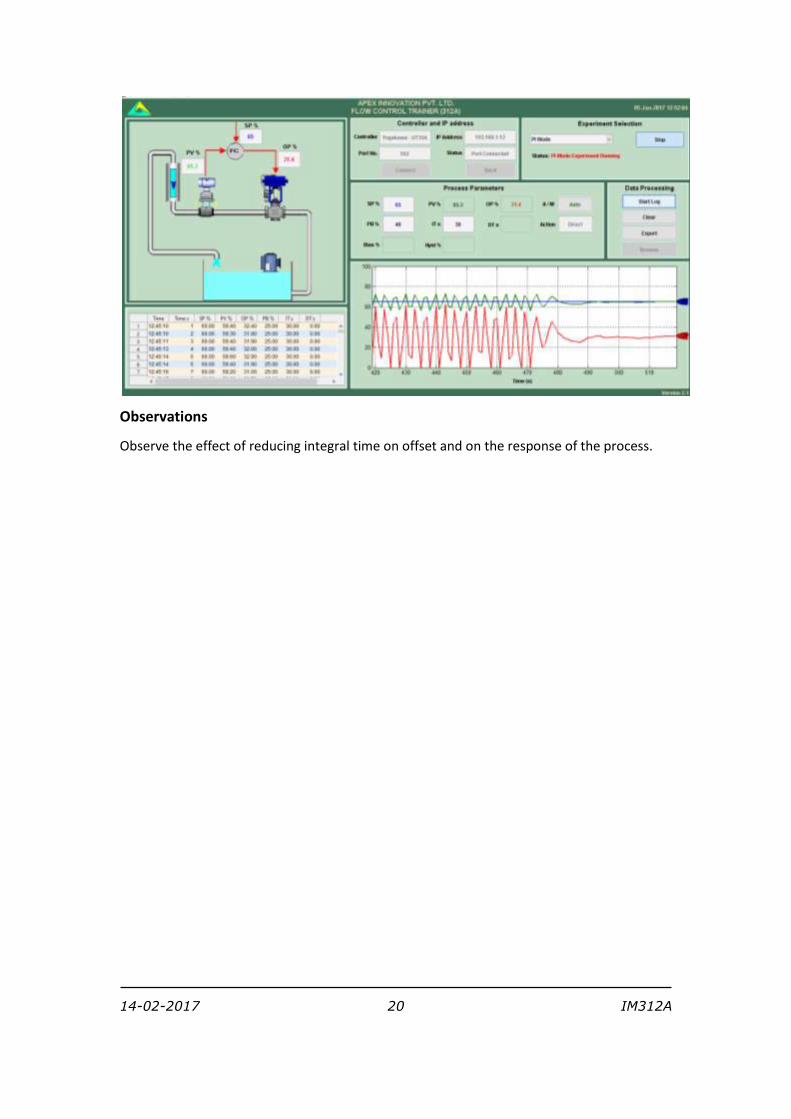
Select PD Mood and click Start
Set the proportional band estimated from Proportional control (P only) Set derivative time
to 0 and integral time=6000 sec.
Set the set point to desired value (@70%). Allow the process to reach at steady state. Note
the response of the system.
Switch the controller to manual mode Increase the derivative time by 1 sec. Switch to Auto
mode and apply step change to the set point by 5 to 10%. Note the response of the system.
Increase the derivative time gradually and observe the process response for step change.
14-02-2017 22 IM312A
Observations
Compare the steady state response of the PD controller with PI controller obtained in the
previous experiment.
Note the effect of noisy flow measurement on the derivative action.
14-02-2017 23 IM312A
6 Study of proportional integral derivative controller
Switch on electric supply. Switch on Mains.
Switch on the pump and adjust the bypass valve to set rotameter flow at 100 LPH.
Switch on the compressed air source and adjust the air regulator to set supply air pressure at
@ 2 kg/cm^2
Switch on the computer.
Double click on Apex_Process_Trainers icon on the desktop.
Select product Flow Control Trainer (312A)
Select Yokogawa (UT35A)
Click Continue
Click Connect
Click on Select Experiment
Select PID Mood and click Start
Switch the controller to manual mode.
Change the proportional band to the value that estimated in proportional controller. Set
integral time and derivative time based on the responses in previous experiments.
Adjust the set point to @ 50 %. Switch the controller to auto mode. Apply step change of
10%. Observe the process response.
Change the proportional band, integral time, derivative time and observe the response of
the process for step change for each change in setting.
14-02-2017 24 IM312A
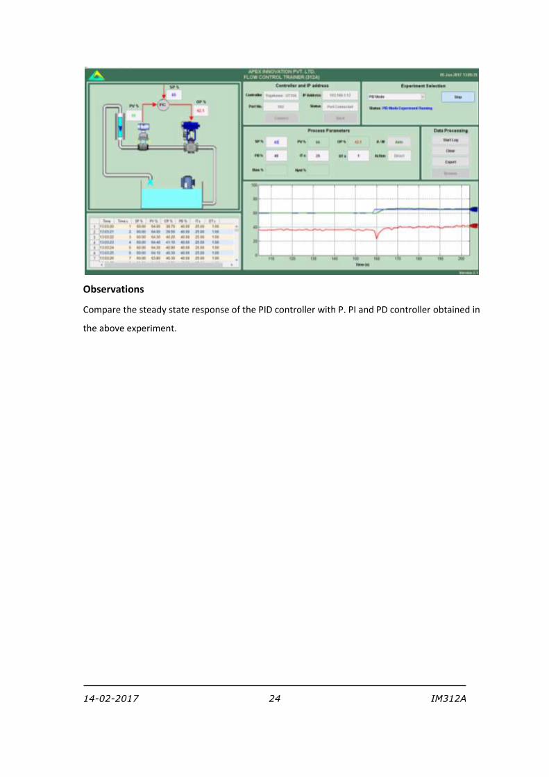
Observations
Compare the steady state response of the PID controller with P. PI and PD controller obtained in
the above experiment.
14-02-2017 25 IM312A
7 Tuning of controller (Open loop method)
Switch on electric supply. Switch on Mains.
Switch on the pump and adjust the bypass valve to set rotameter flow at 100 LPH.
Switch on the compressed air source and adjust the air regulator to set supply air pressure at
@ 2 kg/cm^2
Switch on the computer.
Double click on Apex_Process_Trainers icon on the desktop.
Select product Flow Control Trainer (312A)
Select Yokogawa (UT35A)
Click Continue
Click Connect
Click on Select Experiment
Select Process Reaction and click Start
Adjust controller output, so that the process value is maintained at 70%.
Start data logging.
Apply a 20 - 30 % change to controller output. (Open the control valve) Record the step
response. Wait for the steady state.
Stop data logging.
Plot the step response (Process reaction curve) from stored data. Find out the value of slope
at the point of inflection and time lag.
Calculate P I D settings for different modes.
Select close loop, switch auto manual key to auto mode and then select controller to study.
Set the PID values obtained from the calculations. Apply the step change & observe the
response of the system. Allow the system to reach steady state.
14-02-2017 26 IM312A
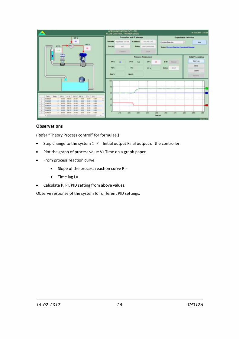
Observations
(Refer “Theory Process control” for formulae.)
Step change to the system P = Initial output - Final output of the controller.
Plot the graph of process value Vs Time on a graph paper.
From process reaction curve:
Slope of the process reaction curve R =
Time lag L=
Calculate P, PI, PID setting from above values.
Observe response of the system for different PID settings.
14-02-2017 27 IM312A
8 Tuning of controller (Closed loop method)
Switch on electric supply. Switch on Mains.
Switch on the pump and adjust the bypass valve to set rotameter flow at 100 LPH.
Switch on the compressed air source and adjust the air regulator to set supply air pressure at
@ 2 kg/cm^2
Switch on the computer.
Double click on Apex_Process_Trainers icon on the desktop.
Select product Flow Control Trainer (312A)
Select Yokogawa (UT35A)
Click Continue
Click Connect
Click on Select Experiment
Select Close Loop and click Start
Set the proportional band value to maximum (Say 100). Set the controller to manual mode
and adjust the output so that the process value reaches to 70%.
Switch the controller to auto mode and decrease the proportional band and apply the step
change to the set point and observe the process response.
Repeat the above procedure and find out correct value of proportional band for which the
system just goes unstable i.e. continuous oscillations are observed in the output of
controller.
Record the ultimate proportional band and ultimate period from the response.
Calculate the PID values from the table. Select the PID controller and apply the parameter
values obtained from the above steps. Observe the response of the process to a step change
with these settings.
14-02-2017 28 IM312A
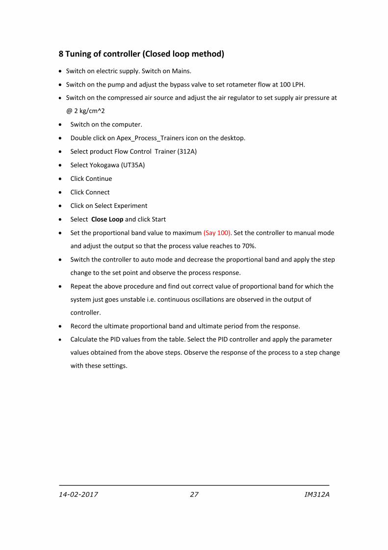
Observations
Record the ultimate proportional band (Pbu) and ultimate period (Tu) from above
experiment.
Calculate PID values by referring theory part for different control actions.
Observe the process response for these settings.
Compare the values obtained with open loop response method.
14-02-2017 29 IM312A
9 Tuning of controller (Using Auto Tuning method)
Switch on electric supply. Switch on Mains.
Switch on the pump and adjust the bypass valve to set rotameter flow at 100 LPH.
Switch on the compressed air source and adjust the air regulator to set supply air pressure at
@ 2 kg/cm^2
Switch on the computer.
Double click on Apex_Process_Trainers icon on the desktop.
Select product Flow Control Trainer (312A)
Select Yokogawa (UT35A)
Click Continue
Click Connect
Click on Select Experiment
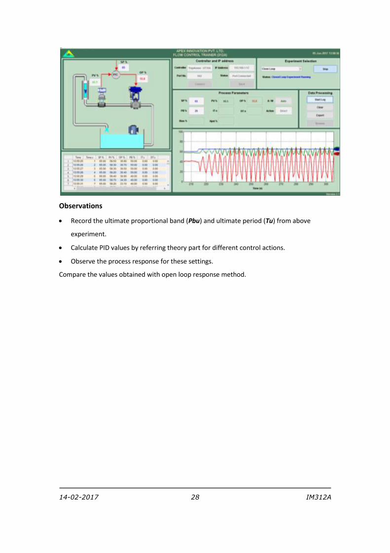
Select Autotuning and click Start
Wait Till Autotune is complete. (Blinking of green LED stops).
Controller automatically finds the PB, IT & DT values.
Find out PID values at different set points /flow rates
Observations
The controller has preprogrammed logic for finding “Auto tune” values. Based on the
response of the process the controller calculates PID values or comes out without finding the
“Auto tune” values.
14-02-2017 30 IM312A
10 To study stability of the system (Bode plot)
Switch on electric supply. Switch on Mains.
Switch on the pump and adjust the bypass valve to set rotameter flow at 100 LPH.
Switch on the compressed air source and adjust the air regulator to set supply air pressure at
@ 2 kg/cm^2
Switch on the computer.
Double click on Apex_Process_Trainers icon on the desktop.
Select product Flow Control Trainer (312A)
Select Yokogawa (UT35A)
Click Continue
Click Connect
Click on Select Experiment
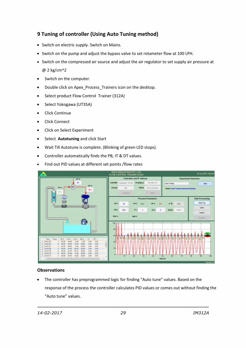
Select Stability analysis and click Start
Start data logging.
Select function generator to apply the sinusoidal input to the output of the controller.
Enter Reference point, Amplitude and Period.
Observe the sinusoidal output of the controller and sinusoidal response of the process.
Log the data for records.
Change the period and repeat the observation for 3-4 different values of the period.
Repeat above procedure for different amplitude and period values.
14-02-2017 31 IM312A
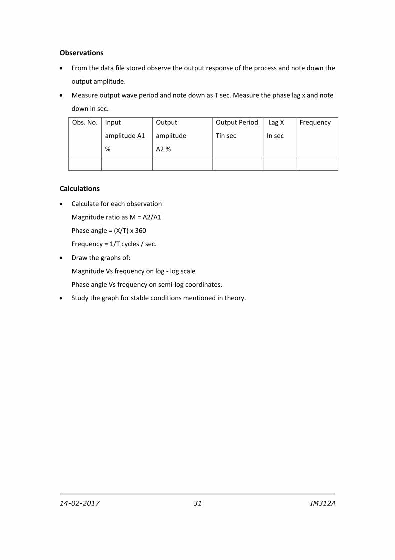
Observations
From the data file stored observe the output response of the process and note down the
output amplitude.
Measure output wave period and note down as T sec. Measure the phase lag x and note
down in sec.
Obs. No. Input
amplitude A1
%
Output
amplitude
A2 %
Output Period
Tin sec
Lag X
In sec
Frequency
Calculations
Calculate for each observation
Magnitude ratio as M = A2/A1
Phase angle = (X/T) x 360
Frequency = 1/T cycles / sec.
Draw the graphs of:
Magnitude Vs frequency on log - log scale
Phase angle Vs frequency on semi-log coordinates.
Study the graph for stable conditions mentioned in theory.