Embed Size (px)
Citation preview
FLOW CHART AND PSEUDO CODE
Flowchart• A Flowchart is a pictorial representation of an
algorithm.• The First flowchart is made by John Von
Newman in 1945.• It is a symbolic diagram of operation
sequence, dataflow, control flow and processing logic in information processing.
• The symbol used are simple and easy to learn.• It is a very help full tool for programmers and
beginners.

The Flowchart• (Dictionary) A schematic representation of a sequence of operations,
as in a manufacturing process or computer program.• (Technical) A graphical representation of the sequence of operations in
an information system or program. Information system flowcharts show how data flows from source documents through the computer to final distribution to users. Program flowcharts show the sequence of instructions in a single program or subroutine. Different symbols are used to draw each type of flowchart.
The Flowchart
A Flowchart– shows logic of an algorithm– emphasizes individual steps and their
interconnections– e.g. control flow from one action to the next
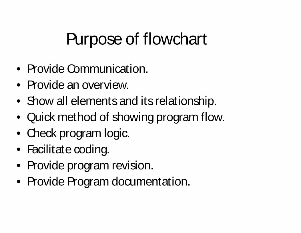
Purpose of flowchart
• Provide Communication.• Provide an overview.• Show all elements and its relationship.• Quick method of showing program flow.• Check program logic.• Facilitate coding.• Provide program revision.• Provide Program documentation.
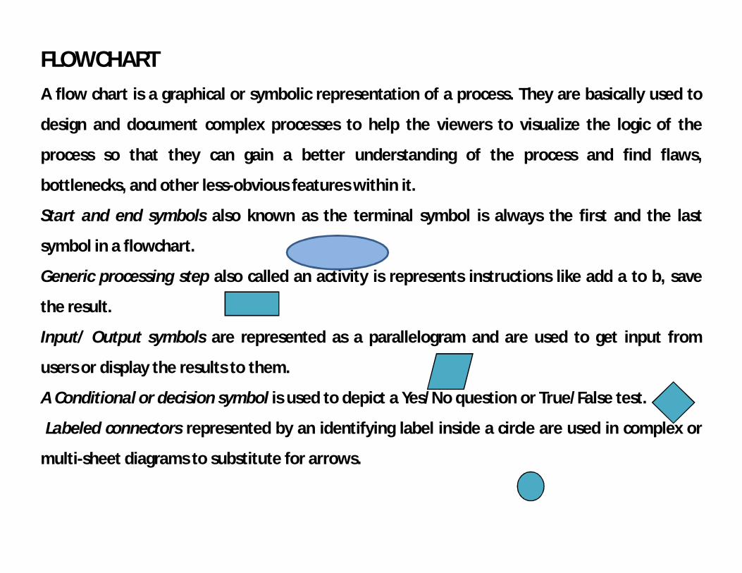
FLOWCHARTA flow chart is a graphical or symbolic representation of a process. They are basically used to
design and document complex processes to help the viewers to visualize the logic of the
process so that they can gain a better understanding of the process and find flaws,
bottlenecks, and other less-obvious features within it.
Start and end symbols also known as the terminal symbol is always the first and the last
symbol in a flowchart.
Generic processing step also called an activity is represents instructions like add a to b, save
the result.
Input/ Output symbols are represented as a parallelogram and are used to get input from
users or display the results to them.
A Conditional or decision symbol is used to depict a Yes/No question or True/False test.
Labeled connectors represented by an identifying label inside a circle are used in complex or
multi-sheet diagrams to substitute for arrows.
Symbols used in flowchart
• All symbols are of different shape and size.• All have specific meaning and use.• The ANSI ( American National Standard
Institute) group categories symbols in 3 types basic, specialized and additional symbols.
• These institution and standardized these basic symbols for use.
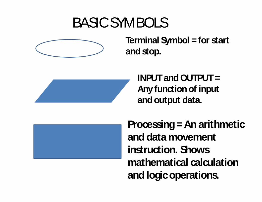
BASIC SYMBOLSTerminal Symbol = for start and stop.
INPUT and OUTPUT = Any function of input and output data.
Processing = An arithmetic and data movement instruction. Shows mathematical calculation and logic operations.
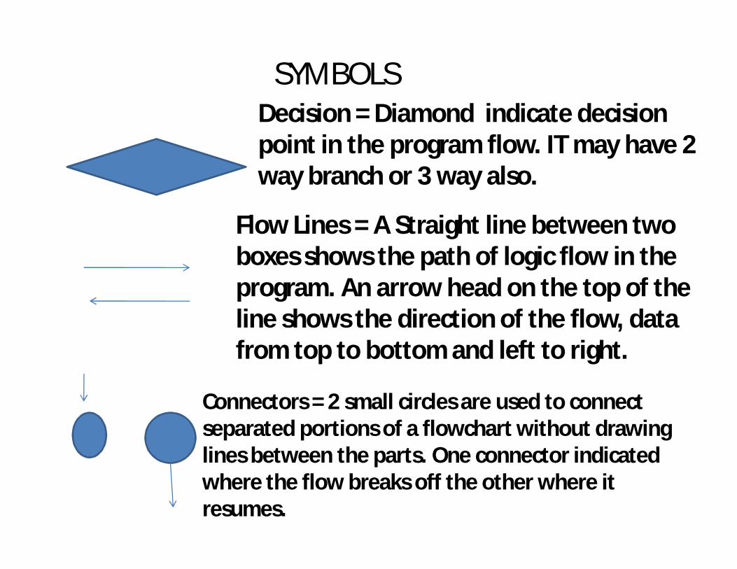
SYMBOLSDecision = Diamond indicate decision point in the program flow. IT may have 2 way branch or 3 way also.
Flow Lines = A Straight line between two boxes shows the path of logic flow in the program. An arrow head on the top of the line shows the direction of the flow, data from top to bottom and left to right.
Connectors = 2 small circles are used to connect separated portions of a flowchart without drawing lines between the parts. One connector indicated where the flow breaks off the other where it resumes.
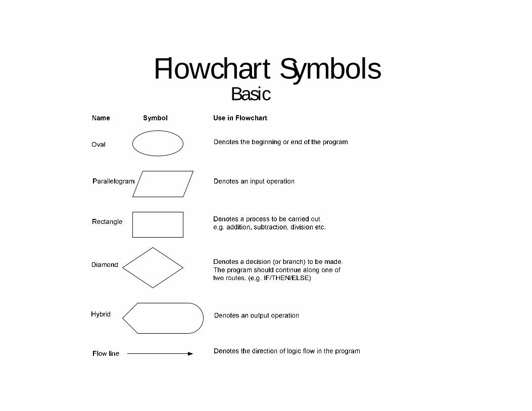
Flowchart Symbols Basic
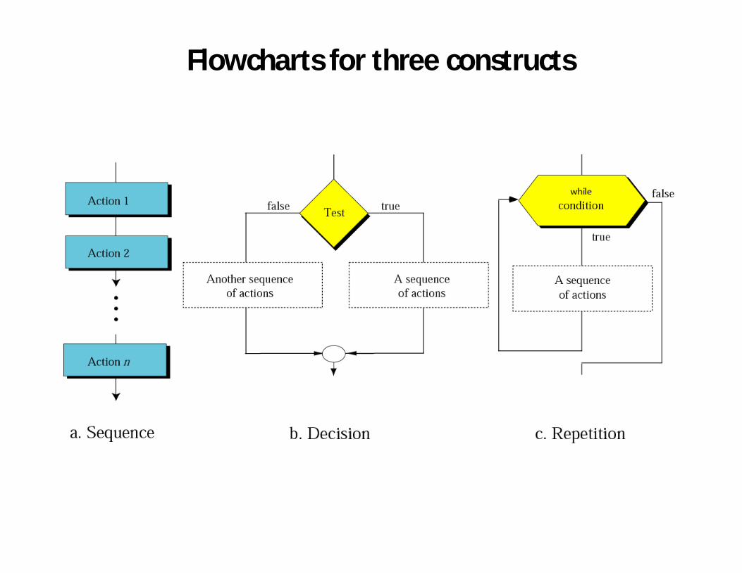
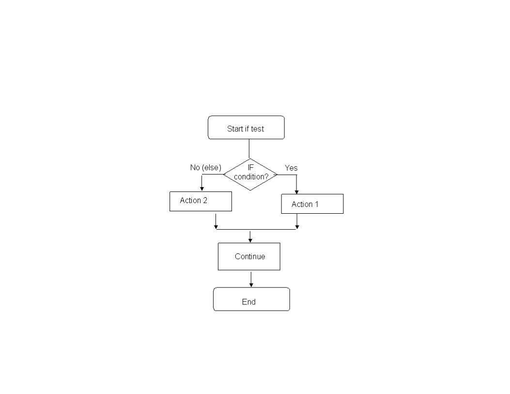
Flowcharts for three constructs
Advantages of flowchart.
• Communication.• Effective analysis.• Proper documentation.• Efficient coding.• Proper debugging.• Efficient program maintenance.• Easy and clear presentation.
Advantages of Flowcharts
A flowchart is a diagrammatic representation that illustrates the sequence of steps that must
be performed to solve a problem. They are usually drawn in the early stages of formulating
computer solutions to facilitate communication between programmers and business people.
Flowcharts help programmers to understand the logic of complicated and lengthy problems.
They help to analyze the problem in a more effective manner
Flowchart is also used for program documentation. Flowchart can be used to debug programs
that have error(s).
Limitation of flowchart
• Complex logic.• Drawing is time consuming.• Alteration and modification.• Redrawn many times.• Difficult to draw and remember.• Reproduction ( replica ).• Technical detail.
Limitations of using Flowcharts
Drawing flowcharts is a laborious and a time consuming activity.
Flowchart of a complex program becomes, complex and clumsy. At times, a little bit of
alteration in the solution may require complete re-drawing of the flowchart
Essentials of what is done may get lost in the technical details of how it is done.
There are no well defined standards that limits the details that must be incorporated in a
flowchart
PSEUDOCODEIt is a form of structured English that describes algorithms. It facilitates the designers to focus
on the logic of the algorithm without getting bogged down by the details of language syntax.
Pseudocode is a compact and informal high-level description of an algorithm that uses the
structural conventions of a programming language. It is meant for human reading rather than
machine reading, so it omits the details that are not essential for humans. Such details
include keywords, variable declarations, system-specific code and subroutines.
It is commonly used in textbooks and scientific publications for documenting algorithms, and
for sketching out the program structure before the actual coding is done. This would help even
the non-programmers to understand the logic of the designed solution.
There are no standards defined for writing a pseudocode because a pseudocode is not an
executable program. Flowcharts can be considered as a graphical alternative to pseudocode,
but are more spacious on paper.
Pseudo code• First produce a general algorithm (one can use pseudo
code) • Refine the algorithm successively to get step by step
detailed algorithm that is very close to a computer language.
• Pseudo code is an artificial and informal language that helps programmers develop algorithms. Pseudo code is very similar to everyday English.

Pseudocode• Pseudocode is an informal description of analgorithm• English-like statements that require less precisionthan a formal programming language.• Allows the designer to focus on the logic of thealgorithm without being distracted by details oflanguage syntax.• A good pseudocode algorithm should beindependent of, but easily translated into, any formalprogramming language.
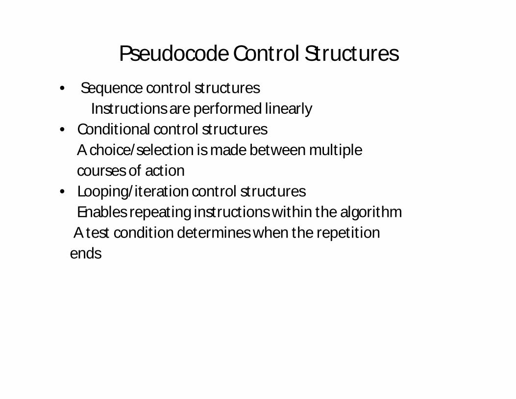
Pseudocode Control Structures• Sequence control structures
Instructions are performed linearly• Conditional control structures
A choice/selection is made between multiplecourses of action
• Looping/iteration control structuresEnables repeating instructions within the algorithmA test condition determines when the repetition
ends
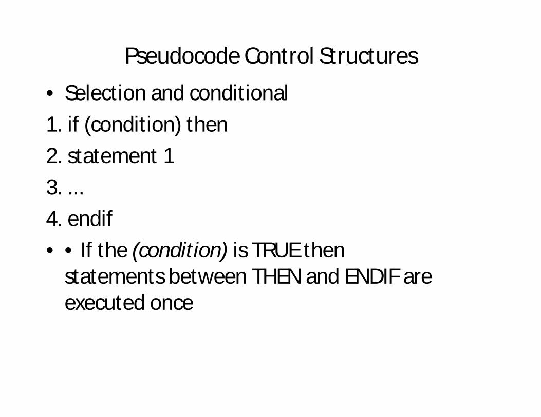
Pseudocode Control Structures• Selection and conditional1. if (condition) then2. statement 13. ...4. endif• • If the (condition) is TRUE then
statements between THEN and ENDIF are executed once
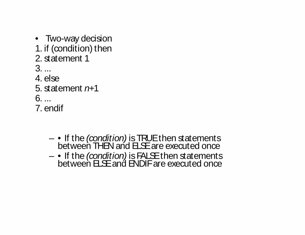
• Two-way decision1. if (condition) then2. statement 13. ...4. else5. statement n+16. ...7. endif
– • If the (condition) is TRUE then statements between THEN and ELSE are executed once
– • If the (condition) is FALSE then statements between ELSE and ENDIF are executed once
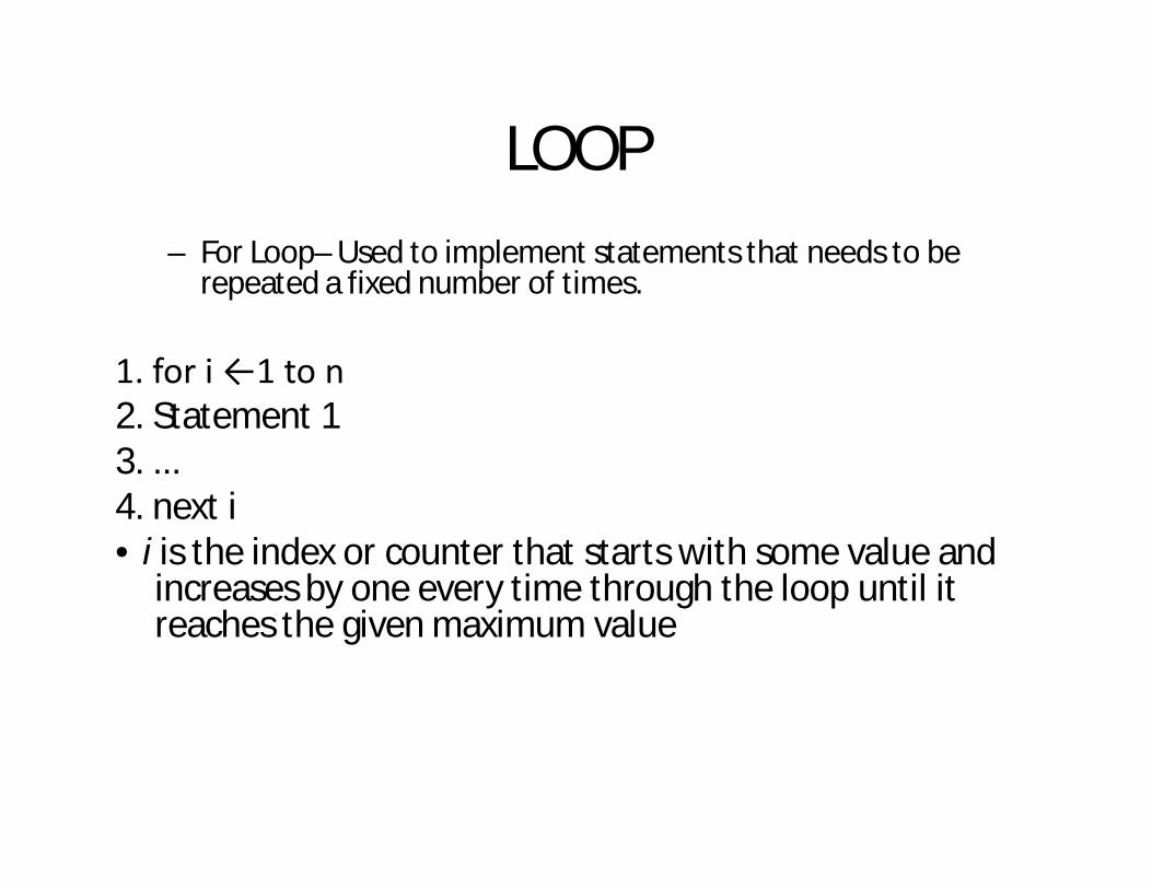
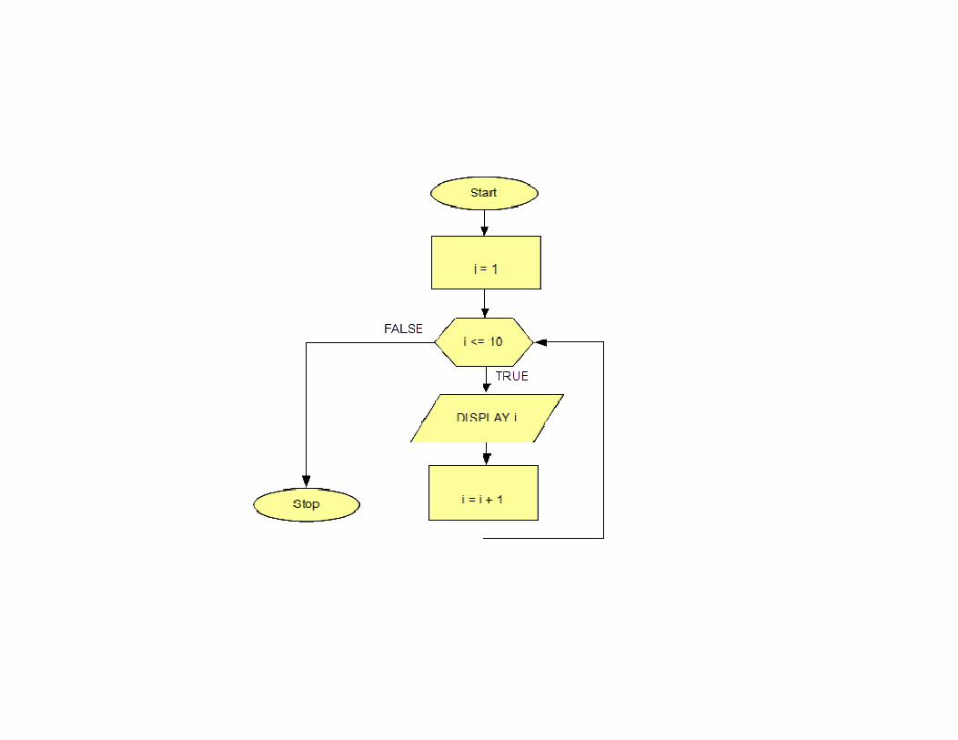
– For Loop– Used to implement statements that needs to be repeated a fixed number of times.
1. for i ←1 to n2. Statement 13. ...4. next i• i is the index or counter that starts with some value and
increases by one every time through the loop until it reaches the given maximum value
LOOP
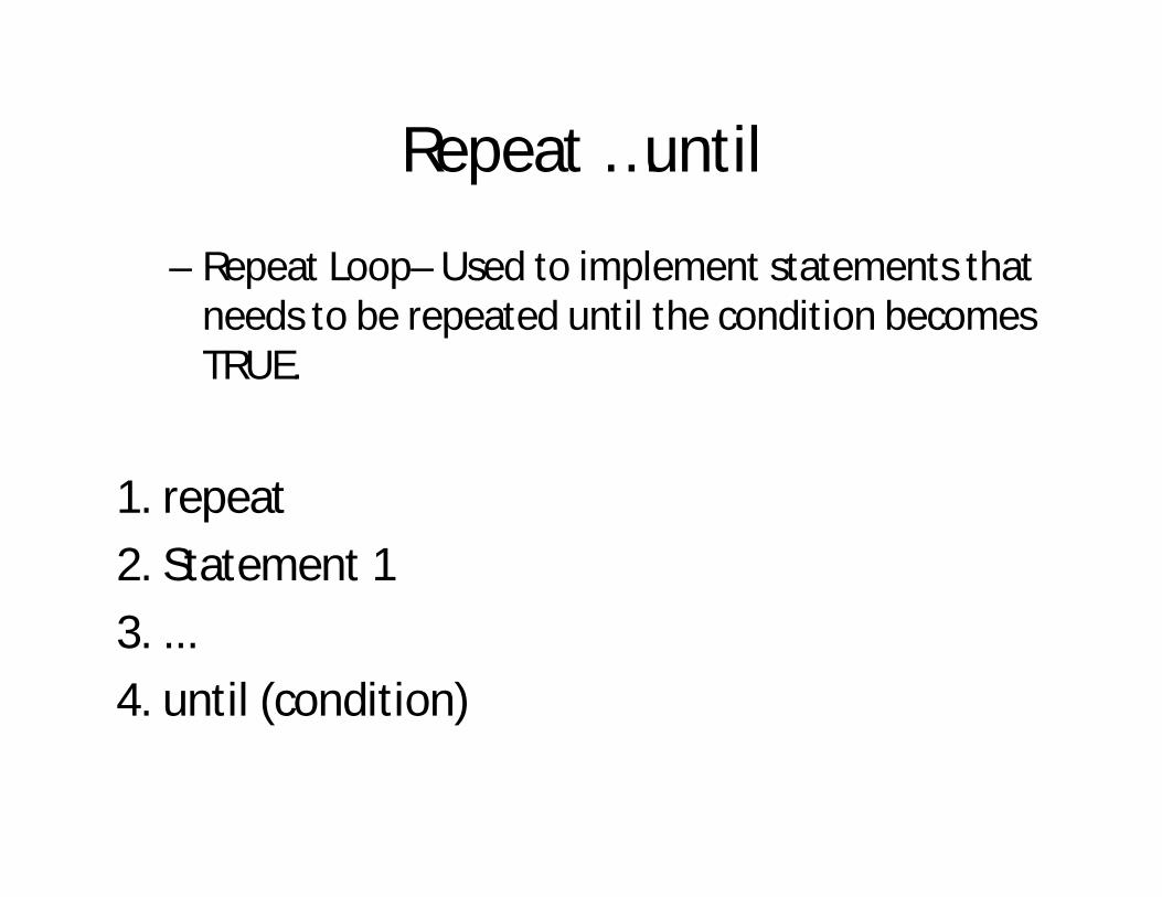
Repeat …until
– Repeat Loop– Used to implement statements that needs to be repeated until the condition becomes TRUE.
1. repeat2. Statement 13. ...4. until (condition)
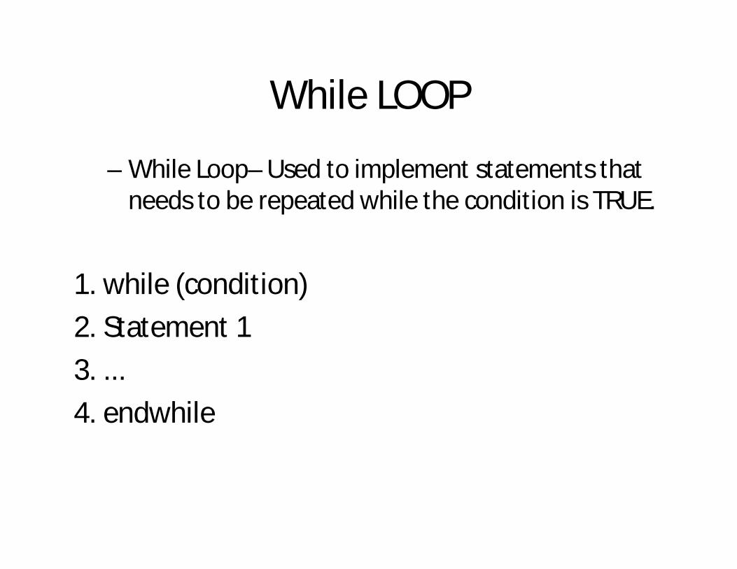
While LOOP
– While Loop– Used to implement statements that needs to be repeated while the condition is TRUE.
1. while (condition)2. Statement 13. ...4. endwhile
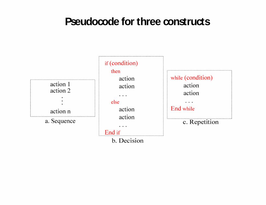
Pseudocode for three constructs
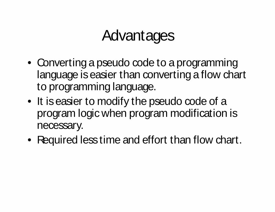
Advantages
• Converting a pseudo code to a programming language is easier than converting a flow chart to programming language.
• It is easier to modify the pseudo code of a program logic when program modification is necessary.
• Required less time and effort than flow chart.
Limitations
• A graphical representation of program logic is not available.
• There are no standard rules to follow in using pseudo code.
• It is very difficult for beginners.
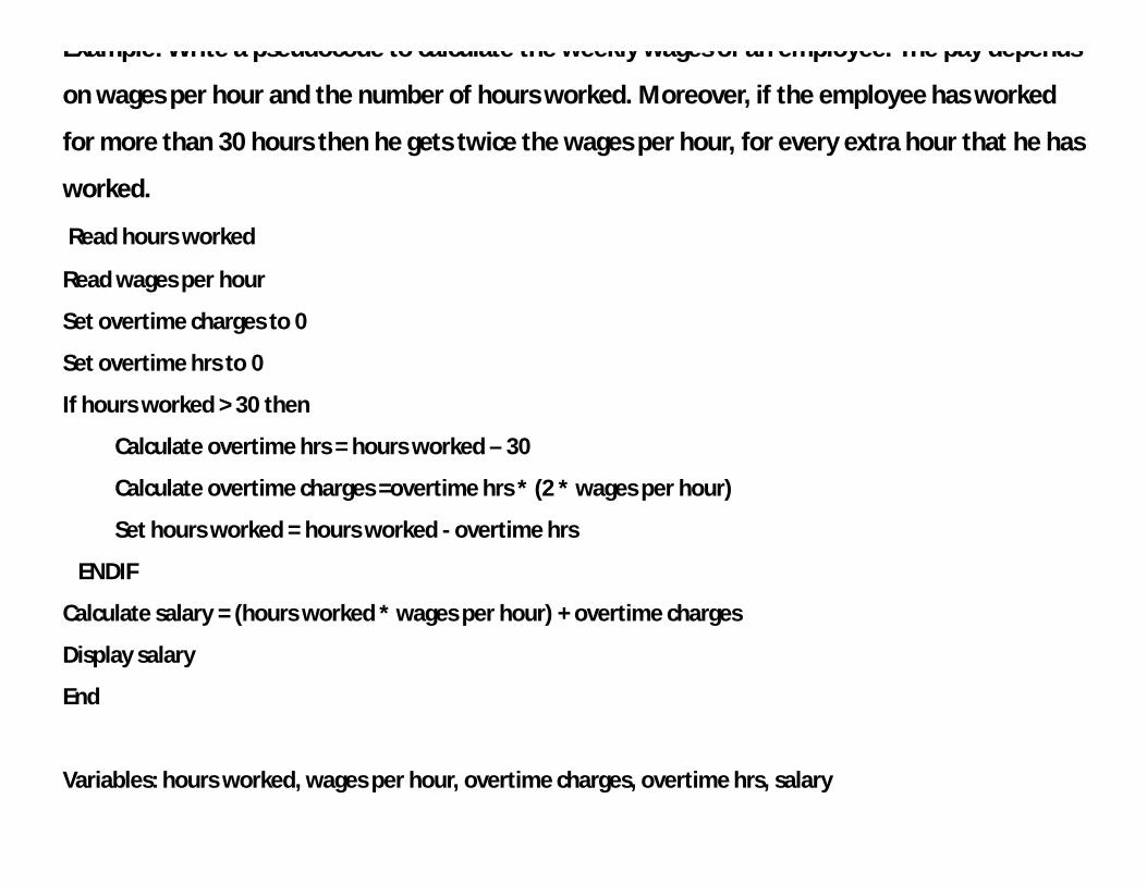
Example: Write a pseudocode to calculate the weekly wages of an employee. The pay depends
on wages per hour and the number of hours worked. Moreover, if the employee has worked
for more than 30 hours then he gets twice the wages per hour, for every extra hour that he has
worked.
Read hours worked
Read wages per hour
Set overtime charges to 0
Set overtime hrs to 0
If hours worked > 30 then
Calculate overtime hrs = hours worked – 30
Calculate overtime charges =overtime hrs * (2 * wages per hour)
Set hours worked = hours worked - overtime hrs
ENDIF
Calculate salary = (hours worked * wages per hour) + overtime charges
Display salary
End
Variables: hours worked, wages per hour, overtime charges, overtime hrs, salary