Embed Size (px)
Citation preview
KTH ROYAL INSTITUTE
OF TECHNOLOGY
Flow and heat transfer in a turbocharger radial turbine
Shyang Maw Lim, Anders Dahlkild, Mihai Mihaescu
CCGEx at the Royal Institute of Technology (KTH) • www.ccgex.kth.se
CCGEx at the Royal Institute of Technology (KTH) • www.ccgex.kth.se
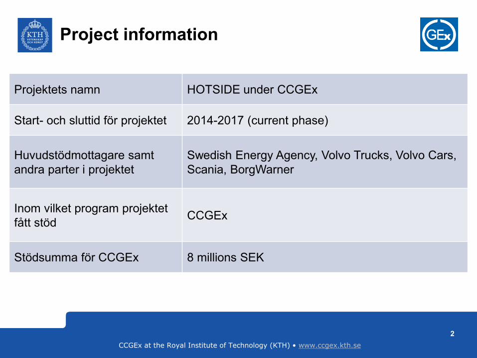
Project information
2
Projektets namn HOTSIDE under CCGEx
Start- och sluttid för projektet 2014-2017 (current phase)
Huvudstödmottagare samt
andra parter i projektet
Swedish Energy Agency, Volvo Trucks, Volvo Cars,
Scania, BorgWarner
Inom vilket program projektet
fått stödCCGEx
Stödsumma för CCGEx 8 millions SEK
CCGEx at the Royal Institute of Technology (KTH) • www.ccgex.kth.se
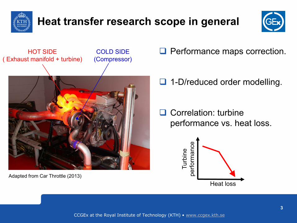
Heat transfer research scope in general
Performance maps correction.
1-D/reduced order modelling.
Correlation: turbine
performance vs. heat loss.
COLD SIDE
(Compressor)
HOT SIDE
( Exhaust manifold + turbine)
Tu
rbin
e
pe
rfo
rma
nce
Heat loss
3
Adapted from Car Throttle (2013)
CCGEx at the Royal Institute of Technology (KTH) • www.ccgex.kth.se
0
0,2
0,4
0,6
0,8
1
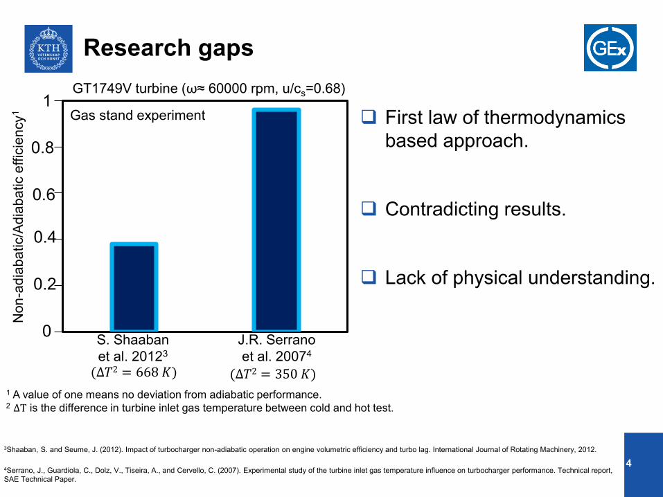
1 2S. Shaaban
et al. 20123
(∆𝑇2 = 668 𝐾)
J.R. Serrano
et al. 20074
(∆𝑇2 = 350 𝐾)
0
1
0.2
0.4
0.6
0.8
GT1749V turbine (ω≈ 60000 rpm, u/cs=0.68)
Gas stand experiment
1 A value of one means no deviation from adiabatic performance.2 ∆T is the difference in turbine inlet gas temperature between cold and hot test.
Research gaps
First law of thermodynamics
based approach.
Contradicting results.
Lack of physical understanding.
Non
-ad
iab
atic/A
dia
ba
tic e
ffic
ien
cy
1
3Shaaban, S. and Seume, J. (2012). Impact of turbocharger non-adiabatic operation on engine volumetric efficiency and turbo lag. International Journal of Rotating Machinery, 2012.
4Serrano, J., Guardiola, C., Dolz, V., Tiseira, A., and Cervello, C. (2007). Experimental study of the turbine inlet gas temperature influence on turbocharger performance. Technical report,
SAE Technical Paper.
4
CCGEx at the Royal Institute of Technology (KTH) • www.ccgex.kth.se
Research questions
5
How heat transfer affects turbine performance (sensitivity)?
What are the heat transfer related losses?
How can we quantify the losses & the effectiveness of resources
utilization?
What is the effects of upstream exhaust manifold (e.g. secondary
flow) on heat transfer and turbine performance?
CCGEx at the Royal Institute of Technology (KTH) • www.ccgex.kth.se
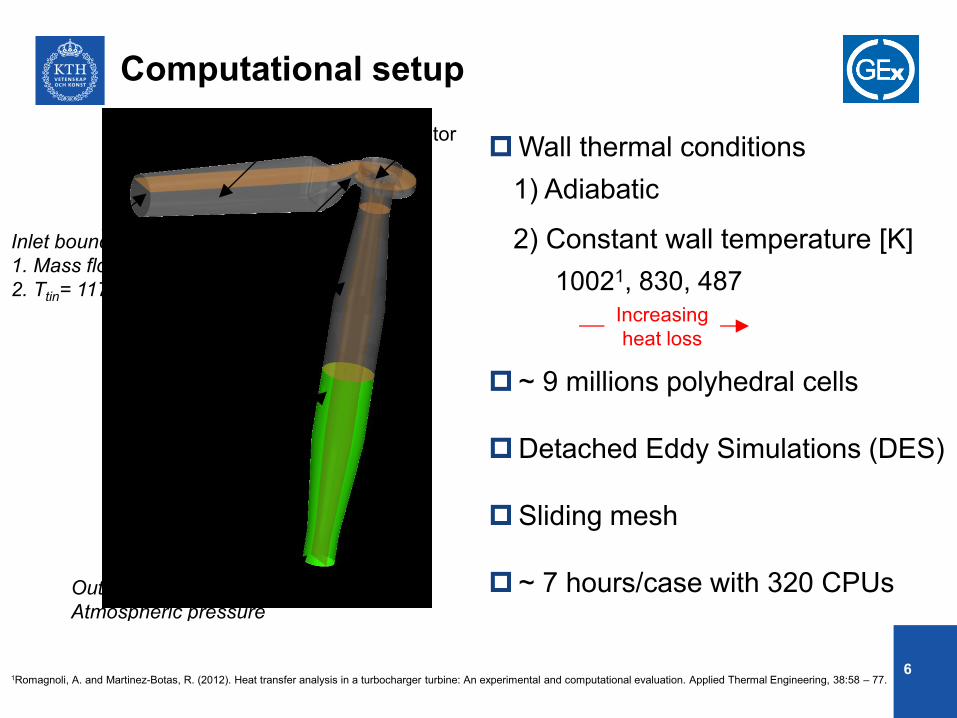
RotorInlet pipe
Scroll
Diffuser
Convergence duct
Inlet boundary:
1. Mass flow inlet
2. Ttin= 1173 K
Outlet boundary:
Atmospheric pressure
2) Constant wall temperature [K]
Wall thermal conditions
~ 9 millions polyhedral cells
Detached Eddy Simulations (DES)
Sliding mesh
~ 7 hours/case with 320 CPUs
1) Adiabatic
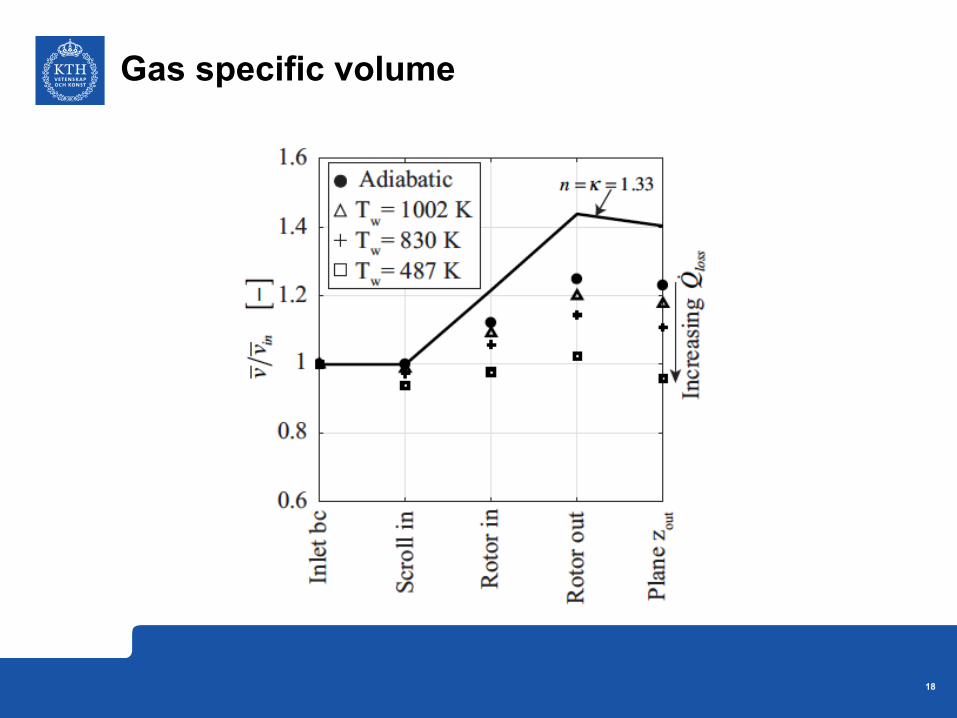
10021, 830, 487
Computational setup
Increasing
heat loss
1Romagnoli, A. and Martinez-Botas, R. (2012). Heat transfer analysis in a turbocharger turbine: An experimental and computational evaluation. Applied Thermal Engineering, 38:58 – 77.6
CCGEx at the Royal Institute of Technology (KTH) • www.ccgex.kth.se
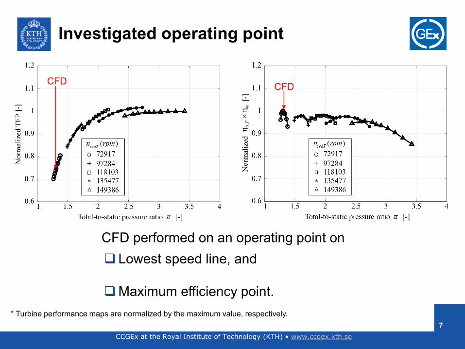
* Turbine performance maps are normalized by the maximum value, respectively.
CFDCFD
CFD performed on an operating point on
Lowest speed line, and
Maximum efficiency point.
Investigated operating point
7
CCGEx at the Royal Institute of Technology (KTH) • www.ccgex.kth.se
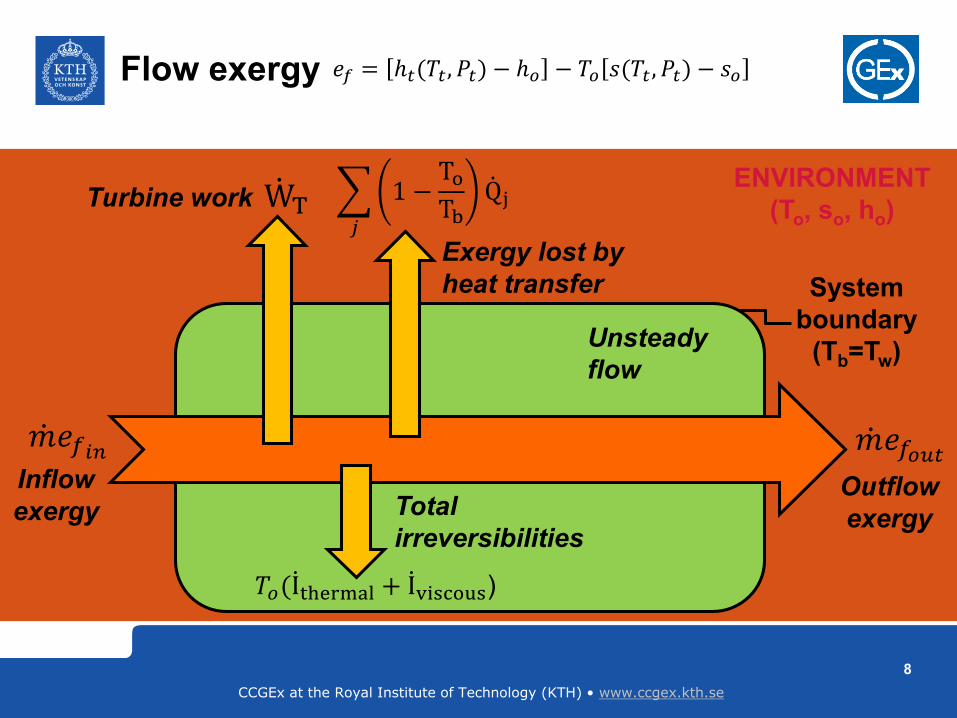
Flow exergy
Turbine work
Exergy lost by
heat transfer
Inflow
exergyOutflow
exergyTotal
irreversibilities
𝑗
1 −ToTb
ሶQjሶWT
System
boundary
(Tb=Tw)
ENVIRONMENT
(To, so, ho)
ሶ𝑚𝑒𝑓𝑖𝑛
𝑇𝑜( ሶIthermal + ሶIviscous)
ሶ𝑚𝑒𝑓𝑜𝑢𝑡
𝑒𝑓 = ℎ𝑡(𝑇𝑡, 𝑃𝑡) − ℎ𝑜 − 𝑇𝑜 𝑠(𝑇𝑡 , 𝑃𝑡) − 𝑠𝑜
Unsteady
flow
8
CCGEx at the Royal Institute of Technology (KTH) • www.ccgex.kth.se
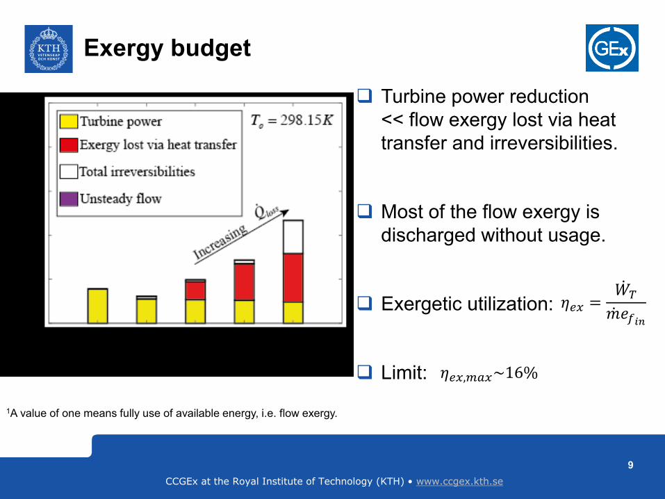
Exergy budget
Turbine power reduction
<< flow exergy lost via heat
transfer and irreversibilities.
Most of the flow exergy is
discharged without usage.
Exergetic utilization:
Limit:
1A value of one means fully use of available energy, i.e. flow exergy.
𝜂𝑒𝑥 =ሶ𝑊𝑇
ሶ𝑚𝑒𝑓𝑖𝑛
𝜂𝑒𝑥,𝑚𝑎𝑥~16%
1
9
CCGEx at the Royal Institute of Technology (KTH) • www.ccgex.kth.se
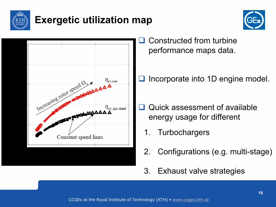
Exergetic utilization map
Constructed from turbine
performance maps data.
Incorporate into 1D engine model.
Quick assessment of available
energy usage for different
1. Turbochargers
2. Configurations (e.g. multi-stage)
3. Exhaust valve strategies
10
CCGEx at the Royal Institute of Technology (KTH) • www.ccgex.kth.se
0 0.2 0.4 0.6 0.8 10
0.2
0.4
0.6
0.8
1
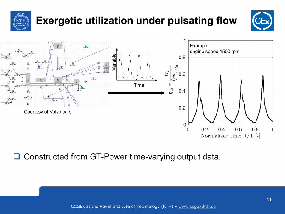
Exergetic utilization under pulsating flow
𝜂𝑒𝑥=
ሶ𝑊𝑇
ሶ𝑚𝑒 𝑓
𝑖𝑛
Courtesy of Volvo cars
Constructed from GT-Power time-varying output data.
Time
Va
ria
ble
Example:
engine speed 1500 rpm
11
CCGEx at the Royal Institute of Technology (KTH) • www.ccgex.kth.se
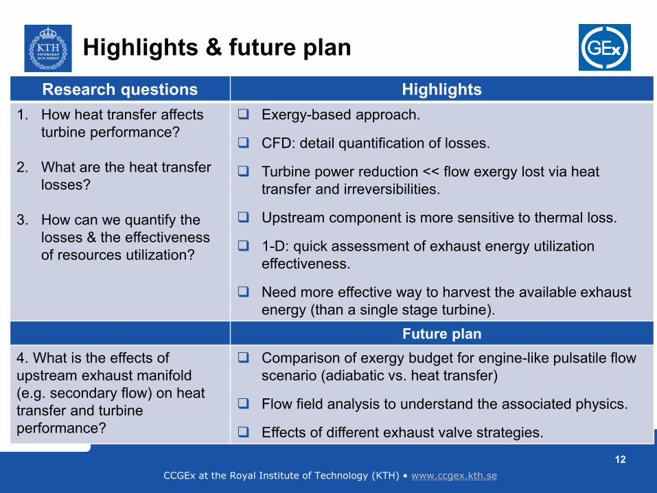
Highlights & future plan
12
Research questions Highlights
1. How heat transfer affects
turbine performance?
2. What are the heat transfer
losses?
3. How can we quantify the
losses & the effectiveness
of resources utilization?
Exergy-based approach.
CFD: detail quantification of losses.
Turbine power reduction << flow exergy lost via heat
transfer and irreversibilities.
Upstream component is more sensitive to thermal loss.
1-D: quick assessment of exhaust energy utilization
effectiveness.
Need more effective way to harvest the available exhaust
energy (than a single stage turbine).
Future plan
4. What is the effects of
upstream exhaust manifold
(e.g. secondary flow) on heat
transfer and turbine
performance?
Comparison of exergy budget for engine-like pulsatile flow
scenario (adiabatic vs. heat transfer)
Flow field analysis to understand the associated physics.
Effects of different exhaust valve strategies.
CCGEx at the Royal Institute of Technology (KTH) • www.ccgex.kth.se
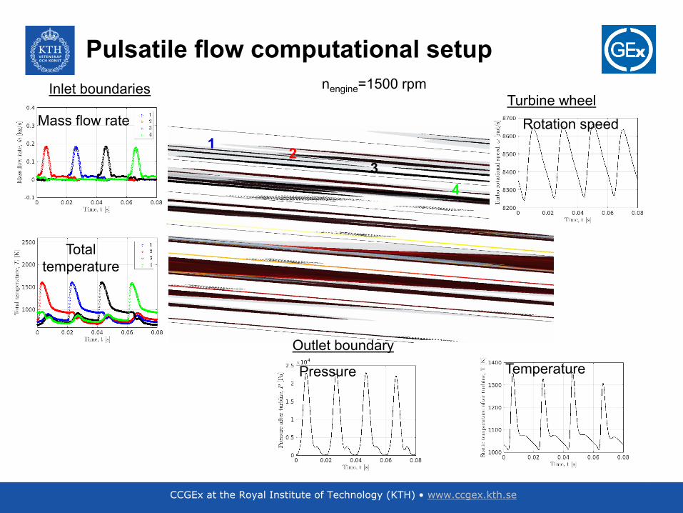
nengine=1500 rpm
12
3
4
Inlet boundariesTurbine wheel
Outlet boundary
Mass flow rate
Total
temperature
TemperaturePressure
Rotation speed
Pulsatile flow computational setup
13

”Charging for the future”
CCGEx at the Royal Institute of Technology (KTH) • www.ccgex.kth.se14
CCGEx at the Royal Institute of Technology (KTH) • www.ccgex.kth.se
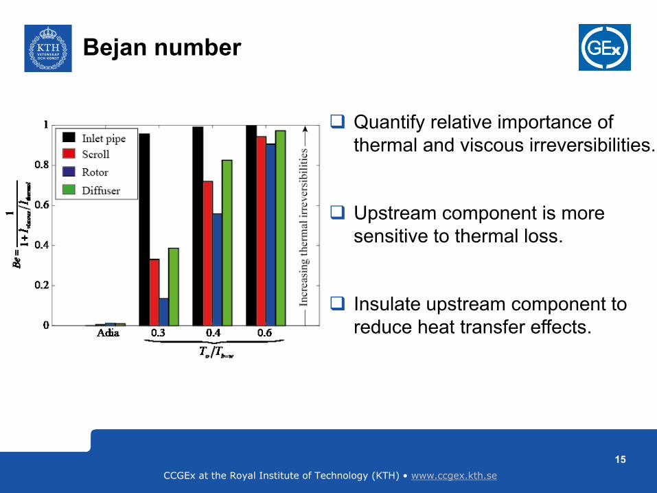
Bejan number
Quantify relative importance of
thermal and viscous irreversibilities.
Upstream component is more
sensitive to thermal loss.
Insulate upstream component to
reduce heat transfer effects.
15
16
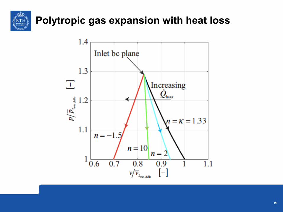
Polytropic gas expansion with heat loss
17
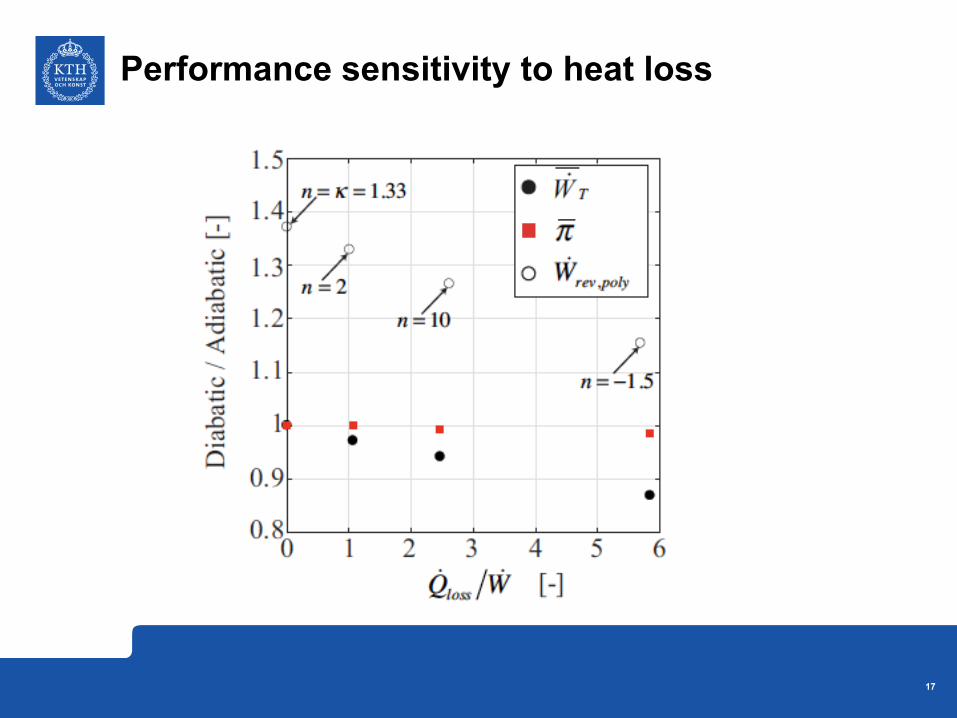
Performance sensitivity to heat loss
18
Gas specific volume
19
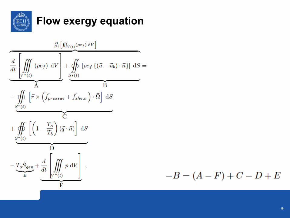
Flow exergy equation
20
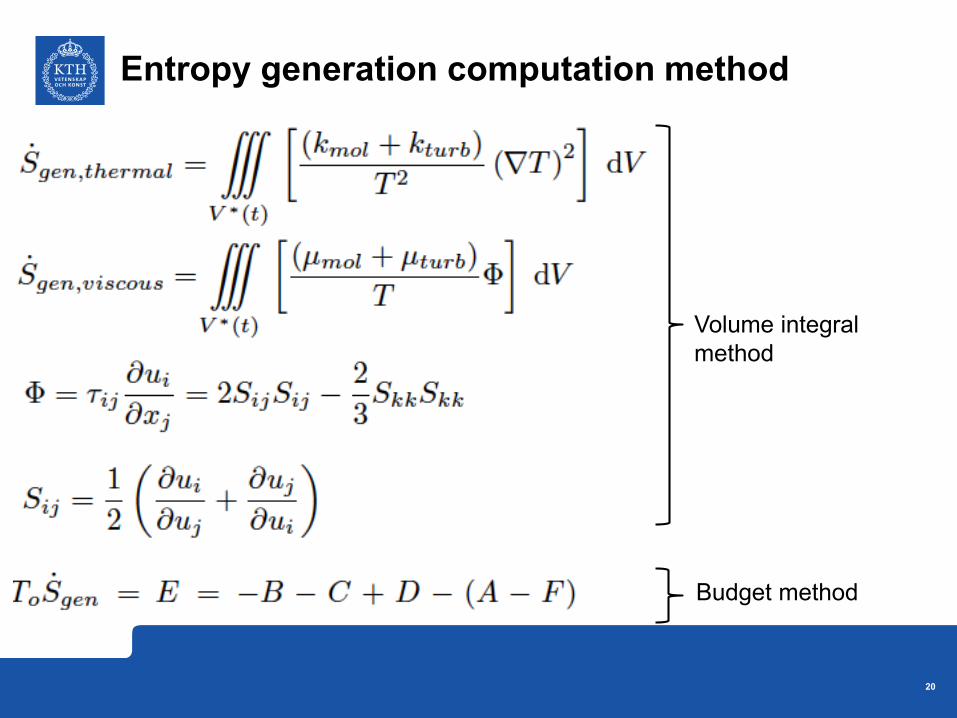
Entropy generation computation method
Volume integral
method
Budget method
21
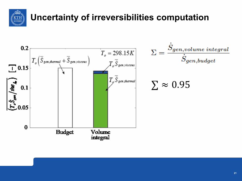
Uncertainty of irreversibilities computation
∑ ≈ 0.95


![Steady and transient conjugate heat transfer analysis of a … · 2018. 6. 6. · heat transfer on turbocharger efficiency under non-adiabatic conditions is presented in [7] along](https://img.pdfslide.us/doc/110x75/5fdb4b7de0d48861ad77fc9f/steady-and-transient-conjugate-heat-transfer-analysis-of-a-2018-6-6-heat-transfer.jpg)