Embed Size (px)
Citation preview
FLORIDA DEPARTMENT OF HEALTH IN MANATEE COUNTY
MEDICAL RESERVE CORPS STANDARD OPERATING PROCEDURES
FOR LOGISTICAL DEPLOYMENT OF ASSETS

This page intentionally left blank for duplication purposes.
Authorization of changes The Manatee County Medical Reserve Corps is established to assist Florida Department of Health in Manatee County (DOH-Manatee) achieve its mission, "To protect, promote & improve the health of all people in Florida through integrated state, county, & community efforts.” In order to accomplish this mission, Manatee County Medical Reserve Corps and DOH-Manatee must ensure its operations are performed efficiently with minimal disruption, especially during an emergency. This document provides planning and program guidance for implementing the Manatee County Medical Reserve Corps Logistical Deployment of Assets to support the DOH-Manatee All Hazards Response – Emergency Operations Plan and programs to ensure the organization is capable of conducting its essential missions and functions under all threats and conditions. As Administrator of the Florida Department of Health in Manatee County, I approve the Manatee County Medical Reserve Corps Logistical Deployment of Assets Plan as presented in this document.
Jennifer Bencie, MD, MSA Administrator Florida Department of Health in Manatee County
Date
David M. Skau Manatee County MRC Coordinator Florida Department of Health in Manatee County
Date

Record of Changes
Nature of Change Date of Change Completed By:
Document Creation 01/2015 Ernie Estevez / Adam DuBois
Additional content added, adjusted, rearranged 04/2016 Mike Zimmermann / David Skau
CONTENTS
INTRODUCTION .................................................................................................. 1
PURPOSE ............................................................................................................ 1
COMMON ACRONYMS ........................................................................................ 1
SOP DOCUMENT CONTROL ................................................................................. 2
ESF-8 REQUEST PROCESS..................................................................................... 2
CONCEPT OF OPERATIONS .................................................................................. 3
ACTIVATION OF MRC MEMBERS ...................................................................................... 3
PREPARING FOR MOBILIZATION ...................................................................................... 4 PERSONAL PREPARATION ................................................................................................................ 4 REPORTING FOR DUTY ..................................................................................................................... 4 MEDICAL/LOGISTICAL INVENTORY .................................................................................................. 4 TOWING VEHICLE PREPARATION ..................................................................................................... 4
PREPARE THE TRAILER FOR DEPLOYMENT .................................................................................. 5
HITCH THE TRAILER TO THE TRUCK .................................................................................................. 5
MOVING THE MEDICAL AID STATION TRAILER TO THE INCIDENT ................................................. 6 PRIOR TO DEPARTURE...................................................................................................................... 7
POSITIONING THE MEDICAL AID STATION TRAILER (MAST) .................................................. 8
UNLOADING ......................................................................................................................... 9 UNLOADING IN INCLEMENT WEATHER ........................................................................................... 9
ASSEMBLING THE MEDICAL AID STATION .................................................................................. 9
OPENING AND CLOSING THE CANOPY ..................................................................................... 10
SET UP INSTRUCTIONS ................................................................................................................... 10 TAKE DOWN INSTRUCTIONS .......................................................................................................... 11
UNLOADING AND OPERATING THE MINI EMERGENCY RESPONSE VEHICLE (MERV) ....................... 12 UNLOADING ................................................................................................................................... 12 OPERATION .................................................................................................................................... 12 LIGHTS AND EMERGENCY SIGNALS ................................................................................................ 13
USING THE GENERATORS...................................................................................................... 13
USING THE FLOODLIGHTS ..................................................................................................... 13
MOUNT LIGHT ASSEMBLY ON STAND ............................................................................................ 14 DO NOT .......................................................................................................................................... 14
USING MIST FANS .............................................................................................................. 15
USING THE MRC IPAD ......................................................................................................... 17
ESTABLISHING A SAFE AND SECURE MEDICAL AID STATION ........................................................ 17
RETURNING TO THE HEALTH DEPARTMENT DURING AN INCIDENT RESPONSE ................................. 17
RAPIDLY LOAD AND RELOCATE ASSETS DURING INCIDENT RESPONSE ........................................... 18
RAPID OPTIONS FOR OTHER GEAR .......................................................................................... 18
LOADING THE TRAILER ......................................................................................................... 19
NORMAL LOADING ORDER ............................................................................................................ 19
MINI EMERGENCY RESPONSE VEHICLE.................................................................................... 19
BEFORE CLOSING TAILGATE, LOAD: ............................................................................................... 20
DEPARTING AN INCIDENT AND RETURNING TO THE HEALTH DEPARTMENT .................................... 20
ON ARRIVAL AT HEALTH DEPARTMENT ................................................................................... 20
DEMOBILIZATION ................................................................................................................ 21 GENERAL ........................................................................................................................................ 21 MEDICAL ASSETS ............................................................................................................................ 21 LOGISTICAL ASSETS ........................................................................................................................ 22 ELECTRONIC ASSETS ....................................................................................................................... 22 EQUIPMENT AND GEAR ................................................................................................................. 23
APPENDICES ...................................................................................................... 24
APPENDIX 1: KEYS .............................................................................................................. 24
APPENDIX 2: FUELING ......................................................................................................... 25
FUEL CANS ...................................................................................................................................... 25 TRUCK FUEL .................................................................................................................................... 25 GENERATOR FUEL .......................................................................................................................... 25
APPENDIX 3: DEWALT AIR COMPRESSOR ............................................................................. 26
FEATURES .................................................................................................................................... 26 Pre-START CHECKLIST ............................................................................................................. 27 OPERATING PROCEDURES ....................................................................................................... 28 Shut-down .................................................................................................................................. 29 MAINTENANCE ........................................................................................................................... 29
APPENDIX 4: RADIO COMMUNICATIONS ................................................................................ 31
APPENDIX 5: VEHICLE MECHANICAL PROBLEMS ....................................................................... 33
APPENDIX 6: VEHICLE ACCIDENTS .......................................................................................... 34
APPENDIX 7: OTHER VEHICLE ISSUES ...................................................................................... 35 FLAT TIRE ........................................................................................................................................ 35 FIRE ................................................................................................................................................ 35 LOST ............................................................................................................................................... 35 IGNITION KEY LOCKED IN TRUCK ................................................................................................... 35 PUBLIC ENCOUNTERS ..................................................................................................................... 36
APPENDIX 8: TRAILER CANOPY .............................................................................................. 37
APPENDIX 9: GENERATORS ................................................................................................... 39
GENERAL GUIDANCE ...................................................................................................................... 39 OPERATING THE GENERATORS ...................................................................................................... 40
1
INTRODUCTION The Medical Reserve Corps (MRC) is a unit of pre-identified, trained, and credentialed volunteers in community health and medical services, who will deploy during emergency medical operations and vital public health activities. In Manatee County, the MRC is coordinated by the Florida Department of Health in Manatee County, where both medical and non-medical volunteers are ready to respond to community health emergencies in an organized and structured way. MRC volunteers are called upon to serve alongside of public health, medical and emergency services professionals for emergency first-aid stations, hurricane shelters, mass dispensing of medication, in a disease outbreak investigation or any other public health related threat in which support is needed during operations. A critical component of the MRC is the Logistics group. Logistics volunteers make it possible for emergency medical and public health professionals to work efficiently and effectively. The Logistics group is responsible for: maintaining MRC readiness for immediate response; moving MRC assets to the site of an incident; setting up a fully-operational Medical Aid Station Trailer (MAST); responding to needs of doctors, nurses, and other medical and public health professionals, and demobilization to restore MRC assets to readiness within a 2-day period after the incident.
PURPOSE This Standard Operating Procedure (SOP) Manual guides the mobilization, deployment, use, and demobilization of assets related to an MRC Incident Response. Principal assets include a towing vehicle, a trailer, a Mini Emergency Response Vehicle (MERV), medical supplies and equipment (Medical Supply Cart), and logistical supplies, gear, and equipment (Logistics Cabinet). This manual is used to train members of the logistics team, and inform medical and public health volunteers in the MRC of basic logistical procedures.
COMMON ACRONYMS Command IC ICS LSC MD MOC
Incident Command Incident Command System Logistics Section Chief Medical Director Medical Operations Chief
Other AWG MERV GFI DOH MRC SOP MAST
American Wire Gauge Mini Emergency Response Vehicle Ground-Fault Interrupter Department of Health Medical Reserve Corps Standard Operating Procedures Medical Aid Station Trailer
2
SOP DOCUMENT CONTROL
Custody: The MRC Coordinator will maintain a digital record of the SOPs, and the original-signature hard copy.
Digital distribution: MRC website. This format allows for MRC members to view the SOPs with smart phones. Some reformatting and redaction may be needed if the document is publicly accessible.
Hardcopy distribution: The mobile team will have two mission copies, one for the trailer and one for the truck. Mobile copies will be printed on waterproof paper (“Rite-in-the Rain,” etc.) and bound in waterproof covers. Another copy will be kept in the MRC Ready Room 65.
Revisions and updates: Any MRC member may report errors, oversights, new information, or other needed changes to the MRC Coordinator. Page revisions will be made as needed, at the Coordinator’s discretion.
Performance and System Audits: The MRC Coordinator will delegate a team to assess the SOPs performance following any major medical incident response. In the absence of such an event, a system’s audit will be performed every second anniversary of this document’s approval.
ESF-8 REQUEST PROCESS In the event of, or need for, additional State resources, the following process will be used:
Contact the MRC coordinator David Skau (941-465-0715) or Adam DuBois (941-405-7347).
They will contact Manatee County Emergency Management (941-748-3501) and ask to speak with the ESF-8 desk.
If warranted, they will run the request past the IC or EM chief. They will then contact the State Warning Point to request additional resources.
Strict adherence is expected of this Order of Operation. Your compliance is much appreciated.
3
CONCEPT OF OPERATIONS
ACTIVATION OF MRC MEMBERS The MRC Coordinator, Incident Commander (IC) or Logistics Section Chief (LSC) will contact MRC Logistics members with instructions on where and when to report. This notification may be an email, phone call, or automated Health Alert Network (HAN) notification through the State Emergency Responder’s & Volunteers of Florida (SERVFL) / Everbridge system.
You will receive an advance digital copy of the Incident’s controlling documents or a hard copy of the mission parameters upon reporting.
Mission parameters are described by a standard set of Incident Command System (ICS) forms complied into an Incident Action Plan (IAP) (See Box 1).
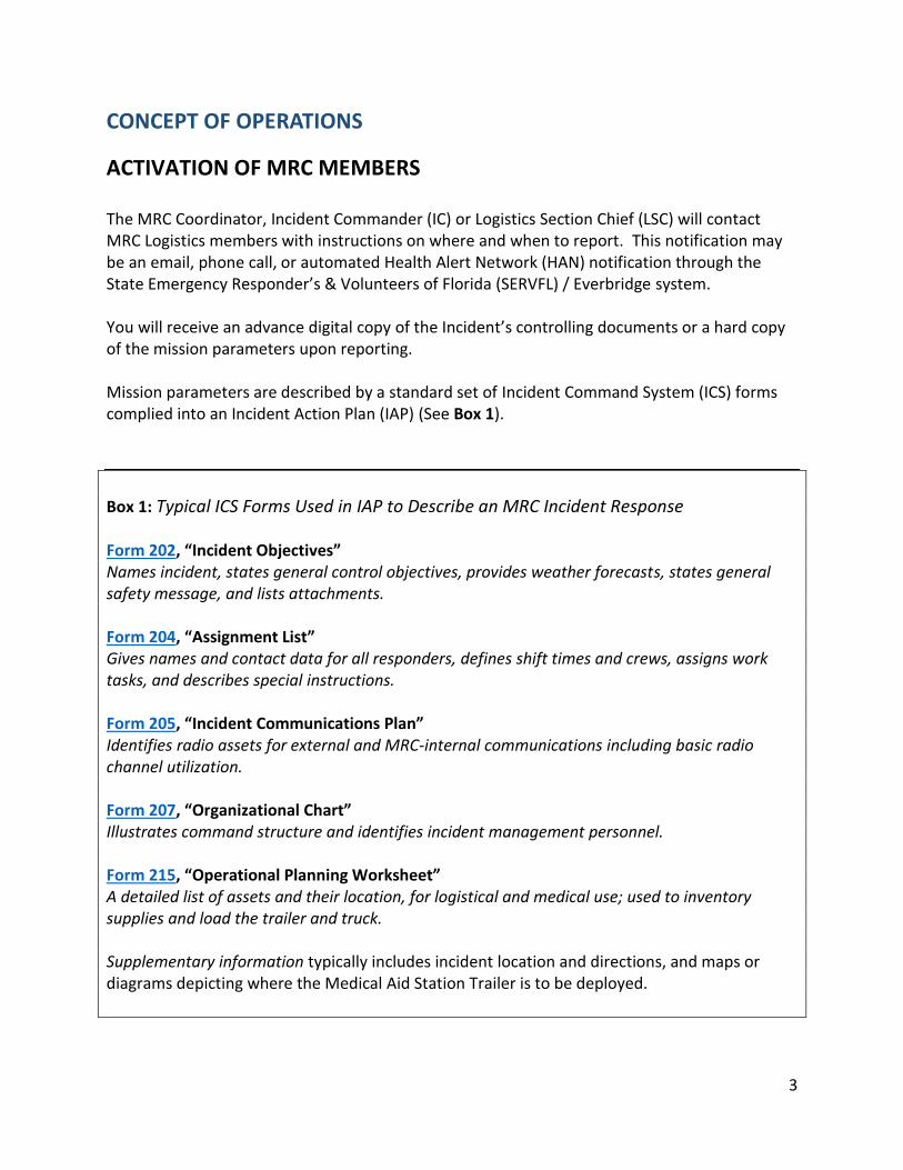
Box 1: Typical ICS Forms Used in IAP to Describe an MRC Incident Response Form 202, “Incident Objectives” Names incident, states general control objectives, provides weather forecasts, states general safety message, and lists attachments. Form 204, “Assignment List” Gives names and contact data for all responders, defines shift times and crews, assigns work tasks, and describes special instructions. Form 205, “Incident Communications Plan” Identifies radio assets for external and MRC-internal communications including basic radio channel utilization. Form 207, “Organizational Chart” Illustrates command structure and identifies incident management personnel. Form 215, “Operational Planning Worksheet” A detailed list of assets and their location, for logistical and medical use; used to inventory supplies and load the trailer and truck. Supplementary information typically includes incident location and directions, and maps or diagrams depicting where the Medical Aid Station Trailer is to be deployed.
4
PREPARING FOR MOBILIZATION
PERSONAL PREPARATION
Before deploying, be sure you have a Family Emergency Plan in place. Logistics members must wear MRC shirts, official MRC ID badge, and closed-toe shoes. Responders will prepare their MRC backpacks according to mission needs: clothes for cold or foul weather, sun and mosquito treatments, energy snacks and water, cell phone and charger, etc.
REPORTING FOR DUTY
Your specific assignment will either order you to report to the Florida Department of Health in Manatee County, an incident scene, or tell you when your first shift begins later in the response. Do not report to an incident unless ordered to, as this will be considered self-deployment and you may be refused at the scene. If you encounter law enforcement or other first-responder personnel while en route, produce your MRC ID badge and a digital or hard copy of your orders. If you encounter other difficulties reaching the Health Department or incident location, contact the MRC Coordinator, IC, or LSC for this mission. Upon reporting, notify the Logistics Section Chief that you are present and describe any circumstances affecting your ability to complete your shift(s).
MEDICAL/LOGISTICAL INVENTORY
Note: Inventory can be taken in advance of deployment once the inventory planning worksheet (ICS 215) for the mission has been released by the IC or LSC. The Medical Operations Chief (MOC) will supervise the inventory of medical supplies in the MRC Medical Supply Cart. If advance inventory is not possible before deployment, the LSC and MOC will advise.
TOWING VEHICLE PREPARATION
Obtain keys (Appendix 1).
Check and top tire pressures (60 psi cold; 60 psi for spare) using the Westward Jump -Starter and Compressor (for 12V power supply) or the DeWalt air compressor (for 110-120V power supply).
Release truck hood with latch on driver’s side door frame.
Check levels of oil, water, and other fluids including battery.
Check head/tail lights, flashers, and emergency lights.
Verify safety contents of truck: fire extinguisher, road safety kit, first aid kit.
Obtain fuel for truck and generators (Appendix 2). This may be done in advance of deployment or upon leaving the Health Department as the mission launches.
5
PREPARE THE TRAILER FOR DEPLOYMENT
Obtain keys (Appendix 1).
Lower trailer tailgate and open side door.
Inspect and tighten tie-down straps as necessary.
Unplug small and large battery chargers from wall outlet and then disconnect both chargers from the MERV.
Verify that the MERV key is in the vehicle.
Load perishable medical supplies upon MOC authorization.
Load other inventory items as needed from the Ready Room.
Inspect condition of radios and radio batteries prior to leaving.
Turn off the air conditioner, lights, radios (at power strips), and portable refrigerator.
Close and lock trailer tailgate.
Leave side door unlocked.
Inspect and top off all tire pressures (60 psi cold) using the Westward Jump Starter and Compressor (for 12V power supply) or the DeWalt air compressor (for 110-120V power supply). See Appendix 3 for details on compressor use.
Verify that canopy is securely closed.
Disconnect trailer power supply. Disconnect power cord from building first. The extension cord stays with the trailer.
Stow the cord that is connected to the trailer in the trailer’s electrical service hatch and close hatch cover.
TOTAL WEIGHT OF TRAILER CARGO MUST NOT EXCEED 6,500 LBS.
HITCH THE TRAILER TO THE TRUCK
Position truck so the hitch ball is near (2-3 feet) of the trailer’s hitch receiver and the truck has a clear path upon departing with trailer in tow.
Raise the two load supports under the back end of the trailer.
Place truck transmission in “PARK.”
Unlock the steel battery case mounted at the front of the trailer.
Inspect battery connections and tighten if needed.
Switch voltmeter to “ON.”
Check battery voltage (at least 11.5 V).
Switch voltmeter to “OFF.”
Find remote control for PROJACK yard wheel in top drawer of file cabinet inside the trailer door.
Press “ON.”
Press “ON” switch located on remote control receiver unit mounted to top of yard wheel assembly.
Using the center toggles, lower the yard wheels to the ground.
6
Continue lowering so the tongue of the trailer is lifted upward enough to remove wood blocks under the tongue stand.
Place blocks in trailer.
Crank the stand up.
Experiment with the left and right sets of toggles to master control of the wheels, then “walk” the trailer close to the hitch ball on the truck.
Open hitch receiver on the trailer and adjust tongue elevation so the receiver is slightly higher than the top of the ball. Make sure the hitch latch is fully open.
Lower the tongue so the hitch comes down over the ball. The hitch is correct when the latch can be completely closed.
Raise yard wheels to the top of their travel.
Turn off the remote control and the remote control receiver.
Return remote control to file cabinet in trailer; close and lock side door.
Inspect male and female wiring connectors and clean as needed.
Connect trailer lights to truck electrical system.
Test connection by turning on the truck’s emergency flashers and look for trailer tail lights to flash.
Test turn signals, brake and running lights.
Hang trailer chains to hitch frame under the truck bed, with latch hooks facing toward the bumper.
The chains are too long if they touch the ground, so add a few twists to each chain as needed.
MOVING THE MEDICAL AID STATION TRAILER TO THE INCIDENT Destination and route will be provided as an Incident Map for pre-planned missions. In the event of an urgent or evolving Incident, the route and destination may be radioed to the Logistics team by the IC or other authority.
Only authorized county and state employees, as well as pre-approved MRC volunteers may operate the towing vehicle.
Drivers should use 2-wheel drive for all use on paved roadways.
Safety belts MUST be worn at all times while driving in vehicles.
Transmission override “overdrive” should be disengaged when transporting the Medical Aid Station Trailer (MAST).
7
PRIOR TO DEPARTURE
Consult the Incident Radio Communications Plan for radio assignments (Vertex; 800 MHz, etc.). See Appendix 4 for radio guidance.
Take radio(s) assigned to Mobile Team from the Ready Room and test, before departing.
Return all keys normally stowed in KEY BOX A and KEY BOX B.
Each member of the Mobile Team will make a final inspection of truck, bed contents, hitch, and trailer before departing.
Recheck trailer lights.
Adjust rear view mirrors on truck. Departure
By radio, request authorization to depart DOH-Manatee from the IC and/or LSC.
Note date, time, and mileage on truck log.
Go to Field Operations Center for fuel, if needed (Appendix 2).
The Mobile team may be sent to a staging area or rendezvous site first, or directly to the incident site. Maintain radio communications with the IC/LSC.
Only MRC personnel and county employees may ride in the truck unless the IC or LSC authorizes it.
No one shall ride in the truck bed or trailer at any time.
The truck is equipped with emergency red and amber lights. To turn the lights on, toggle the appropriate switch on the light-bar control panel mounted to the dashboard.
Red lights are to be used ONLY during an EMERGENCY, with consent from the IC.
Amber lights are to be used for non-emergency situations, to convey “CAUTION.”
If there is a breakdown or accident, the safety of, and first aid for, MRC personnel and other persons are priorities. Refer to Appendix 5, Appendix 6, and Appendix 7 for guidance.
8
POSITIONING THE MEDICAL AID STATION TRAILER (MAST) The LSC, working in consultation with the Medical Operations Chief and Safety Officer, will supervise the location and assembly of the Medical Aid Station Trailer. In general, detach the trailer from the truck: the truck may be needed for other purposes.
At night or in poor visibility, distribute head lamps before positioning the trailer.
The truck can also be used to light the setup area for the station. Do not use headlights while the engine is off, to protect battery charge.
Detach trailer by removing chains and electrical connection.
Release the hitch latch (a hammer-tap may be needed).
Unlock the trailer side door.
Use the remote control to lower yard wheels until the trailer tongue rises enough to lift the hitch off the ball.
Walk the trailer to its final location.
Place wood blocks under the tongue stand.
Lower stand until it is close to the wooden blocks.
Raise wheels to lower the trailer onto the blocks.
Use the stand crank to level the trailer.
Turn off the remote control and receiver.
Return the remote control to the file cabinet.
Park and lock the truck.
Make sure the dome light is NOT left in the ON position.
Deploy the trailer’s rear load supports located near the tail gate.
9
UNLOADING The LSC will direct unloading. Before unloading and/or setting up the trailer, ensure that all staff are wearing deployment vests and the portable radios have been turned on and handed out. THE PVC VINYL STRIP DOOR IS TO BE KEPT IN THE FULLY-CLOSED POSITION WHENEVER THE A/C UNIT IS HEATING OR COOLING, AND WITH PATIENTS.
Unlock and lower the tailgate/ramp
In general, the order for unloading is:
MERV
Logistics Cabinet #1
Medical aid tent(s)
Portable refrigerator
Other materials and supplies
Generators
Do not tangle loose tie-down straps.
As each tie-down is removed, coil the straps around their handle/ratchet mechanism.
Keep all coiled straps together in one place to simplify loading when the Incident has ended and it is time to load and leave.
UNLOADING IN INCLEMENT WEATHER
Open the trailer’s side canopy (Appendix 8).
Place the MERV under the canopy.
Set up the Medical Aid tent and put any other trailer contents under the tent as you unload.
ASSEMBLING THE MEDICAL AID STATION Raise the MRC First Aid banner as soon as you’re ready to accept patients.
Supervised teamwork is needed to erect the Medical Aid tent (Appendix 9), trailer canopy, and generators.
Do not attempt to assemble any of the following components without prior training or supervision:
Generator system (Appendix 10)
Floodlights
Mist fans
After the generators are running, turn on the AC and other electrical devices.
Check PROJACK battery charge at each shift change. Batteries can be charged while the trailer is power by generators or shore power.
10
OPENING AND CLOSING THE CANOPY
SET UP INSTRUCTIONS
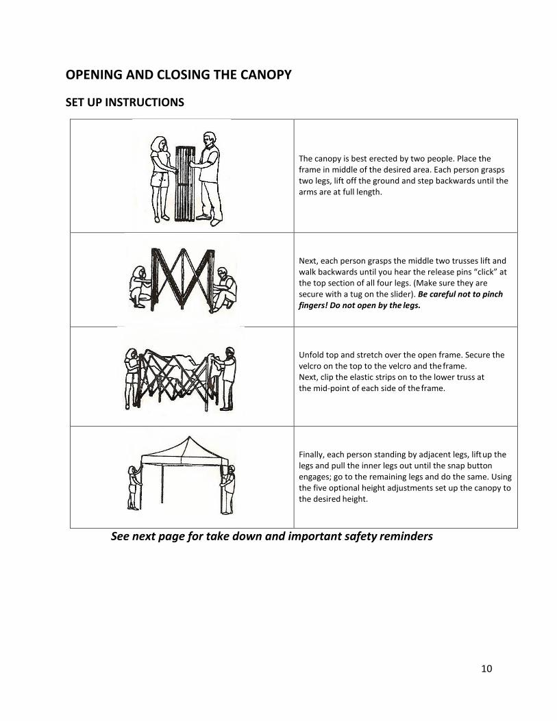
The canopy is best erected by two people. Place the frame in middle of the desired area. Each person grasps two legs, lift off the ground and step backwards until the arms are at full length.
Next, each person grasps the middle two trusses lift and walk backwards until you hear the release pins “click” at the top section of all four legs. (Make sure they are secure with a tug on the slider). Be careful not to pinch fingers! Do not open by the legs.
Unfold top and stretch over the open frame. Secure the velcro on the top to the velcro and the frame. Next, clip the elastic strips on to the lower truss at the mid-point of each side of the frame.
Finally, each person standing by adjacent legs, lift up the legs and pull the inner legs out until the snap button engages; go to the remaining legs and do the same. Using the five optional height adjustments set up the canopy to the desired height.
See next page for take down and important safety reminders

11
TAKE DOWN INSTRUCTIONS
It is recommended to remove the top for storage. Unclip the elastic straps and remove the top and fold.
Pull all four release pins on each leg. Pulls at the slider to make sure pins are disengaged.
Each person goes to the center of opposing sides. Grasps the top trusses of the middle section, lift and walk towards each other until the canopy is at arm’s length. Each person then grabs two legs and close completely.
ALWAYS use either a stake kit or weight bags to secure the unit from winds.
Never leave canopy unattended in stormy weather, and take down canopy in heavy winds.
Do NOT store canopy when wet.
Clean with mild detergent. Never put top in washing machine.
12
UNLOADING AND OPERATING THE MINI EMERGENCY RESPONSE VEHICLE (MERV)
UNLOADING
Before unloading, verify that battery chargers have been disconnected from wall outlets and vehicle. An experienced driver should drive the MERV off the trailer.
Remove tie-down straps.
Ensure that the ramp is completely down and that there is ample open space behind the trailer.
Assign helpers hold the PVC vinyl strip door apart for visibility and safety.
Read the directions on the dashboard.
Turn the ignition key to ON and check battery charge.
Toggle the drive switch to REVERSE.
A “backing-up” alarm will sound whenever the direction selector is set to REVERSE.
Slowly back up, parallel to the trailer’s right wall, moving slightly to avoid hitting the right wheel well or right rear corner of the door frame.
Before descending ramp ask “All Clear?”
OPERATION
The MERV plays a critical role in transporting victims in need of first aid to a Medical Aid Station. The MERV is also intended to patrol, travel to and from the Incident Command Center and other incident facilities, and retrieve and deliver consumables and/or perishable supplies (food, water, ice, fuel, etc.). An experienced driver, preferably a member of the Logistics team, or Medical Operations Chief will operate the MERV.
The LSC informs the driver of the destination and purpose of the trip.
Another MRC member may accompany the driver as needed.
If the trip is intended to bring someone needing medical attention to a Medical Aid Station, AT LEAST ONE member of the Medical team must accompany the driver. The Medical Operations Chief will assign the person(s).
Before departing, ask the Medical team member(s) if all support assets (water, ice, blanket, etc.) or medical assets (first aid kit, defibrillator, etc.) are loaded and secured.
If asked by Medical team member(s), the driver will assist with tasks related to assessing patient condition, providing first aid, stabilizing the patient, loading the patient onto the MERV, and securing the patient for the return trip.
13
LIGHTS AND EMERGENCY SIGNALS
To operate the headlights move the white plastic toggle switch to ON. The MERV is equipped with red and amber flashing lights and siren. These are to be used only in an emergency. To initiate emergency lights:
Obtain IC or Medical Ops approval to use these lights.
Flip the steel toggle switch in the center of the dashboard to UP position. To operate the siren:
Push the button on the microphone for the desired sound.
Push talk button on the side of the handset to use the PA feature.
USING THE GENERATORS The LSC will determine the number of units to deploy, and their location. Refer to Appendix 10 for instructions, and remember:
GENERATORS POSE LIFE-THREATENING HAZARDS OF FIRE, ELECTROCUTION AND CARBON MONOXIDE POISONING.
Before starting generator(s) make sure the air conditioner, portable refrigerator, radios, and lights are turned OFF.
USING THE FLOODLIGHTS Operating tips:
Look for, and use latches and twist knobs on stands and light assemblies.
Do not force any component during assembly.
The light assemblies can be used without being mounted on stands, for illuminating as needed.

14
MOUNT LIGHT ASSEMBLY ON STAND
Unfold stand legs and extend stand to the desired height.
Attach light assembly.
Use latches to move lights to desired position.
Connect to power supply making sure electrical connections are protected from standing water.
Use ground-fault interrupter (GFI) protected circuits whenever possible. Use no more than 50 feet of extension cord.
Use only 14, 12, or 10-gauge (AWG) cords for these lights.
Press button-switch to turn lights ON/OFF.
Buttons may have weather covers- remove to operate switch.
Each lamp head has a 3-position switch for two light levels and OFF.
Always turn each lamp head OFF before unplugging the work light.
Spare 500W Halogen bulbs are located inside the light assembly and stand.
DO NOT
Touch hot lens, guard or enclosure.
Look directly at lighted bulb.
Touch the bulb at any time. (Use a soft cloth).
To replace a bulb, consult the USER MANUAL in the black file cabinet.
15
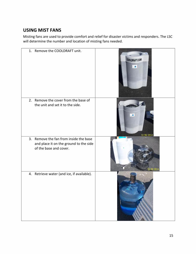
USING MIST FANS Misting fans are used to provide comfort and relief for disaster victims and responders. The LSC will determine the number and location of misting fans needed.
1. Remove the COOLDRAFT unit.
2. Remove the cover from the base of
the unit and set it to the side.
3. Remove the fan from inside the base
and place it on the ground to the side of the base and cover.
4. Retrieve water (and ice, if available).
16
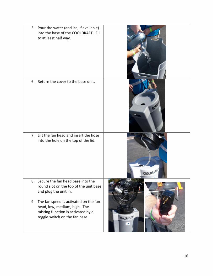
5. Pour the water (and ice, if available) into the base of the COOLDRAFT. Fill to at least half way.
6. Return the cover to the base unit.
7. Lift the fan head and insert the hose
into the hole on the top of the lid.
8. Secure the fan head base into the
round slot on the top of the unit base and plug the unit in.
9. The fan speed is activated on the fan head, low, medium, high. The misting function is activated by a toggle switch on the fan base.
17
USING THE MRC IPAD The MRC Coordinator or IC will provide an iPad for Logistical, Medical, and Safety team use. The device is to be kept inside the trailer at all times. All MRC members are encouraged to use the device to:
Record consumption of consumables and perishables.
Make notes on how methods or operations can be improved.
Note any durable gear that will require replacement, repair, servicing, or cleaning during demobilization.
The IC will set up the device for use. If it is necessary to restart the device:
Unlock the device using the MRC access code.
Go to Desktop: ignore updates dialog box.
Open Notes and access the latest file.
Add new notes.
ESTABLISHING A SAFE AND SECURE MEDICAL AID STATION The Safety Officer will supervise the deployment of barricades, hazard tape, and cones.
Generators are to be barricaded.
Hang hazard tape from the tail gate’s steel cables. The IC or LSC will direct security measures during extended deployments.
As a general principle, the Logistics team should make sure that the deployed Medical Aid Station Trailer is never left completely unattended.
RETURNING TO THE HEALTH DEPARTMENT DURING AN INCIDENT RESPONSE
If ordered to return with the truck to the Health Department for supplies or other purposes:
Inspect truck for trailer, nursing, generator, fuel or other materials and supplies that should be left with the Medical Aid Station Trailer.
Deliver personal items including MRC backpacks, clothing, etc. to the LSC or a designate staying with the Station.
Driver or Mobile Crew should keep their personal gear with them.
18
Determine whether the truck has sufficient fuel for a round-trip or plan to stop at the Field Operations Center to refuel during the trip.
Inform the LSC of fuel status before leaving.
Radio your local contact regarding your arrival at the DOH-Manatee facility.
The IC or LSC will arrange your radio contacts for access to the DOH-Manatee grounds and building if you will be arriving after hours.
Radio your local contact to secure the building and grounds when leaving DOH-Manatee facility.
Inform the IC or LSC that you are returning to the Medical Aid Station Trailer.
RAPIDLY LOAD AND RELOCATE ASSETS DURING INCIDENT RESPONSE Any significant or sudden change in an incident’s parameters may require a rapid relocation of mobile assets. Upon being told to prepare for relocation:
Immediately stop and disconnect the generator(s), and hitch the trailer to the truck.
Dismantle Medical Aid tent and drop trailer canopy.
Load assets that normally go along the left wall of the trailer. MERV options for more urgent loading:
If there is time to allow generator(s) to cool (enough to touch), load units and then load the MERV.
If not, and the new Incident Response site is within battery range, drive the MERV to it.
Stow the hot generators inside the trailer where the MERV is normally stowed, taking care that tie-down straps avoid hot parts and that other cargo will not come into contact with the generators.
If the new site is beyond the vehicle’s existing battery range, load the MERV first, securing it as far forward as possible while still allowing access through the door.
Then load and secure the hot generators behind the MERV, taking care that tie-down straps avoid hot parts and that other cargo will not come into contact with the generators.
RAPID OPTIONS FOR OTHER GEAR
Nursing carts and logistic cabinets must be loaded and secured in the trailer.
In the event of an urgent relocation, the LSC may order other loose gear (tents, lights, fans, barricades, chairs etc.) to be put into the truck bed and lashed down for transportation to a new site.
19
LOADING THE TRAILER In normal cases the MERV will be loaded last.
Turn off the air conditioner, radios, portable refrigerator, and lights.
Turn the generator(s) OFF and disconnect them from the trailer.
Allow time for the generators and floodlights to cool.
Use mobile headlamps for light after sunset.
Turn the PROJACK battery master switch to ON.
Attach the trailer to the truck.
Turn the PROJACK battery master switch to OFF.
Raise and secure the canopy.
Drain ice chests, rehab cooling/misting fan reservoirs, and thermal rehabilitation chairs if used.
NORMAL LOADING ORDER
Refer to APPENDIX 11. When an incident response is over and the mobile assets are to be returned to the Health Department, the order of loading is:
1. Generators, once cooled to touch. Secure with tie-down straps. 2. Raise and secure the counters attached to the walls. If leaving the site, also stow
barricades against the counter at this time. 3. All gear stowed along the left wall of the trailer, beginning near the front and
working toward the back. Secure with tie-down straps. 4. Gear lashed with tie-down straps to the right wall of the trailer.
MINI EMERGENCY RESPONSE VEHICLE
Clear the MERV path and parking area inside the trailer.
Throw several of the PVS vinyl door slats onto the trailer roof so the driver has a clear view of the interior.
Slowly ascend the ramp, aligning the MERV as close to the right wall as possible without striking the door frame or wheel well.
In normal use, the MERV will be loaded forward, close to but not blocking entry provided by the door.
Turn OFF the ignition. Leave the key in the cup holder.
Set the direction selector to NEUTRAL.
Secure the vehicle with a front strap hooked to a flush-mounted floor tie-down ring.
20
Secure the vehicle with two rear straps.
First strap should run over the Medical Supply Cart, between the cart and cart handle, and down to a tie-down ring.
Second strap should run beneath the Medical Supply Cart to the same ring.
BEFORE CLOSING TAILGATE, LOAD:
Incidental items used until the last minute. Place inside door.
Deployment vests and radios (except for those used by the Mobile Team).
DEPARTING AN INCIDENT AND RETURNING TO THE HEALTH DEPARTMENT
The Mobile team will check truck engine and tires; trailer hitch, trailer light function, and trailer wheels.
Raise the rear load supports.
Other personnel will inspect the grounds for gear and supplies.
Personnel not returning to the Health Department should gather their personal gear (backpack, foul weather gear, etc.).
The Medical Operations Chief, Safety Officer, and/or Logistics Chief will notify the IC that mobile assets and personnel are prepared to return, including destinations and routes.
Upon IC approval, personnel are ordered to stand down.
Personnel with their own transportation may go home.
Personnel using their own vehicle to return to the Health Department should follow the MRC truck and trailer keeping a safe distance in between (in case help becomes needed).
ON ARRIVAL AT HEALTH DEPARTMENT
Detach trailer and lower rear load supports.
Re-establish trailer electrical connection to building.
Open door and turn on all electrical devices requiring continuous power.
Tilt the MERV driver seat forward and connect the small battery charger to the solo battery (closest to the left side of the seat box).
Attach the black charger cable to the negative post, and then attach the red cable to the positive post.
Lower the seat.
Take the custom plug attached to the large battery charger and firmly insert it into the charging slot in front of the driver seat box. The plug is designed to go in at an angle.
Plug the chargers into the trailer’s electrical outlet.
21
DEMOBILIZATION
GENERAL
Demobilization is the process leading to the restoration of MRC readiness for a subsequent incident for which little or no notice may be available. Demobilization is complete when everything is returned, accounted for, repaired or replenished, and all mobile assets are prepared to deploy. The process can begin at an incident as the process of standing down begins. A large component of demobilization occurs after the assets have returned to the Health Department. Depending on the duration and intensity of the closed incident, the MRC Coordinator or IC may assign a special demobilization shift comprising logistical and medical team members, to accomplish the effort.
OUR GOAL IS TO RESTORE COMPLETE READINESS WITHIN 2 WORK-DAYS AFTER THE INCIDENT.
The LSC coordinates demobilization with the MOC. Demobilization team members may be assigned individual duties. After the trailer is parked and powered, tasks include:
Off-loading and securing all perishable or regulated medical supplies and devices.
Arranging for County Fleet Service assistance for mobile assets.
Inspecting and servicing mobile electronic devices.
Emptying the trailer so all contents can be inventoried, inspected, cleaned, repaired, and properly stowed in the Ready Room or trailer, after thoroughly cleaning the inside of the trailer.
Cleaning the MERV, truck interior, and the exteriors of the truck and trailer.
Verifying inventory and providing updated inventory list to MRC Coordinator.
Use a triage approach: throughout demobilization, determine what needs to be replaced; what needs to repaired, and what needs only cleaning and stowing.
MEDICAL ASSETS
The MOC or other medical personnel should demobilize their assets. Consult the MRC iPad for relevant notes. Remove the following from the trailer:
Patient tracking forms and logs, transfer to MRC Coordinator.
AED (defibrillator); CO2 detector; other electronic medical devices.
Medical contents in portable refrigerator-freezer, if any.
Inventory all gear and supplies.
22
Report to MRC Coordinator or IC if any permanent, electronic medical devices are lost, broken, or need warranty servicing as soon as possible.
Clean reusable assets.
Resupply perishables from MRC inventory or ask MRC Coordinator to obtain.
Dispose of sharps and bio-hazardous waste.
LOGISTICAL ASSETS
Thoroughly inspect the truck, trailer, MERV, and generators, and consult the MRC iPad for relevant notes.
As soon as possible, report any repairs or routine maintenance that requires the attention of County Fleet Services or other county assistance to the MRC Coordinator or IC, so the assets can be restored to readiness.
Consult relevant sections of this manual for items to inspect on mobile assets.
Inspect the trailer’s PROJACK electric yard-wheel system including batteries and remote control.
Complete either a Manatee County Incident Report or Vehicle Crash Report (located in glove box) if there are losses, damages, or vandalism to the truck or trailer that were not previously reported and deliver it to the MRC Coordinator or IC.
Give the MRC Coordinator or IC a written list of repairs or maintenance required of County Fleet Services, or other county sources for mechanical or electronic aid.
ELECTRONIC ASSETS
This task should be undertaken by one or more team members with experience in electronics. Assets include radios and chargers, satellite phone and antenna, MRC mobile phones and chargers, digital camera, and battery chargers.
Inventory all gear and supplies. Inspect and test each device and log the results.
Report to MRC Coordinator or IC if any electronic devices are lost, broken, or need warranty servicing as soon as possible.
Clean reusable assets.
Replace batteries from MRC inventory or ask MRC Coordinator to obtain.
Dispose of used batteries using Health Department protocols.
23
EQUIPMENT AND GEAR
Deploy one or two tents close to the trailer, for covered space in which to work on equipment and gear. After a major event, the trailer must be emptied completely in order for the interior to be cleaned. One person will be responsible for small supplies and gear stowed in wall-mounted cabinets and the file cabinet.
Deploy all tents used during the event.
Wash and allow to dry.
Remove Logistics Cabinet #1 and empty it.
Process gear and equipment one item at a time.
Open each cabinet and determine if anything is lost, broken, consumed, or ready to use.
List the cabinet label and contents needing resupply and give the list to the MRC Coordinator.
Repeat process for large storage bins.
Inventory all gear and supplies. Inspect and test each device.
Report to MRC Coordinator or IC if any equipment or gear is lost, broken, or needs warranty servicing as soon as possible.
Clean reusable assets.
Make sure that reservoirs for rehab fans are completely dry.
Pack, stow, and secure each item but do not put any back in the trailer yet.
Clean the interior of the trailer thoroughly.
Wipe all surfaces with microbial disinfectant.
Sweep/mop floor as needed and allow to dry completely.
Inspect and test the air conditioner; clean air filter, test the ceiling and valance lights and replace bulbs as needed before reloading the trailer.
Wash the MERV and let it dry.
Reload the trailer. (APPENDIX 11).
Return keys to KEY BOX C (in the trailer).
Turn off interior lights, double-check MERV chargers, and turn on the AC, radios, and if needed, the portable refrigerator.
Lock the trailer gate and door.
Return other keys.
Submit inventories, other reports to MRC Coordinator.
Log your hours.
24
APPENDICES
APPENDIX 1: KEYS A system of nested key boxes is used to manage MRC keys.
The IC, LSC, or MOC will provide building access and either open the key boxes or provide security codes for key boxes.
Key Box A - lobby area of the annex building
Key Box B - inside Ready Room
Key Box C - inside trailer Key Box A Contents:
Public Health Preparedness (PHP) supply area key
Ready Room door key (interior door)
Key for Key Box B
Key Box B Contents:
Carts 1, 2 and 3
Storage Shed
PHP Office
Trailer (5 keys)
Truck (3 keys)
MRC Beige Cabinet Key Box C Contents:
Trailer keys
Truck, bed cover and fuel keys
Truck key
Key Tag Identifiers:
Red key tags for all mobile assets;
Blue key tags for all non-mobile assets;
Yellow key tags for all duplicate keys.
Black key tags are for buildings and locks.
While keys are in use keep them in your pocket. Do not leave keys in locks. Do not leave keys or locks on top of anything (hood, tailgate, roof, etc.) Return keys to their original box when the keys are no longer needed. Do not leave the truck key in the ignition. The LSC should keep the truck keys after the Medical Aid Station is operational.
25
APPENDIX 2: FUELING
FUEL CANS
Place generator fuel tanks and two large bungee cords in the truck.
After filling, gas cans are secured in the bed of the truck with the bungee cord. Metal jerry cans fit into racks mounted to the trailer tongue. The key to the bed box is with the ignition key. Red cans designated unleaded gasoline, yellow cans designate diesel fuel.
Drive to the Manatee County Field Operations Center, located at 1100 26th Avenue East, less than 2 miles from the Health Department.
Take 6th Avenue or Martin Luther King Jr. Avenue east to 9th Street East. Turn right and drive 1.2 miles south to 26th Avenue East. At 26th, turn left and the Operations Center will be on the right.
So that generators have the freshest possible fuel, transfer any fuel in the portable tanks to the truck. Then top off the truck tank and fill the portable tanks for generators.
TRUCK FUEL
1. Pull up to a pump with the pump near the left-rear quarter of the truck. Turn the truck off.
2. Place pump nozzle into filler and press the desired octane of fuel. 3. Squeeze handle on filler valve to begin filling. 4. Return nozzle to pump and cap to filler; close cover.
NOTE: USE 87 OCTANE GASOLINE
GENERATOR FUEL
Check with the MRC Coordinator to learn when the generators and existing fuel were last used. Decide whether fuel in the generators is still good to use. The generator user’s manual states that fuel less than a month old can still be used. If needed, empty generator fuel tanks.
1. Remove fuel tanks from the truck before filling. 2. After capping each tank, tip it forward to check for leaks. 3. If the seal leaks, re-fit the cap to the tank and retest. 4. Lash fuel tanks the interior of the bed using bungee cords, or tie-down
straps. 5. Remove auxiliary tanks from their racks attached to the trailer tongue. 6. Fill these and place back on their racks, making sure the metal straps are
secure.
26
APPENDIX 3: DEWALT AIR COMPRESSOR
FEATURES
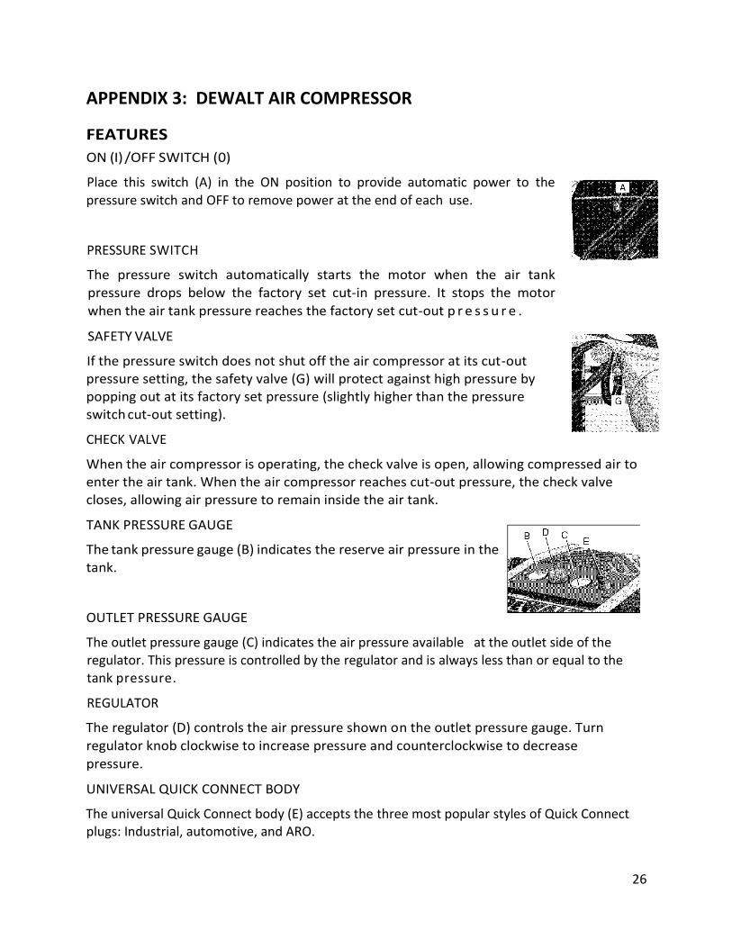
ON (I) /OFF SWITCH (0)
Place this switch (A) in the ON position to provide automatic power to the pressure switch and OFF to remove power at the end of each use.
PRESSURE SWITCH
The pressure switch automatically starts the motor when the air tank pressure drops below the factory set cut-in pressure. It stops the motor
when the air tank pressure reaches the factory set cut-out p r e s s u r e .
SAFETY VALVE
If the pressure switch does not shut off the air compressor at its cut-out pressure setting, the safety valve (G) will protect against high pressure by popping out at its factory set pressure (slightly higher than the pressure switch cut-out setting).
CHECK VALVE
When the air compressor is operating, the check valve is open, allowing compressed air to enter the air tank. When the air compressor reaches cut-out pressure, the check valve closes, allowing air pressure to remain inside the air tank.
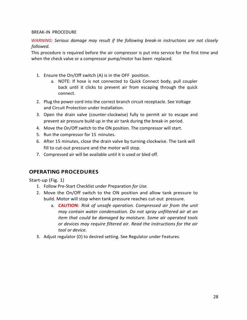
TANK PRESSURE GAUGE
The tank pressure gauge (B) indicates the reserve air pressure in the tank.
OUTLET PRESSURE GAUGE
The outlet pressure gauge (C) indicates the air pressure available at the outlet side of the regulator. This pressure is controlled by the regulator and is always less than or equal to the tank pressure.
REGULATOR
The regulator (D) controls the air pressure shown on the outlet pressure gauge. Turn
regulator knob clockwise to increase pressure and counterclockwise to decrease
pressure.
UNIVERSAL QUICK CONNECT BODY
The universal Quick Connect body (E) accepts the three most popular styles of Quick Connect plugs: Industrial, automotive, and ARO.
27
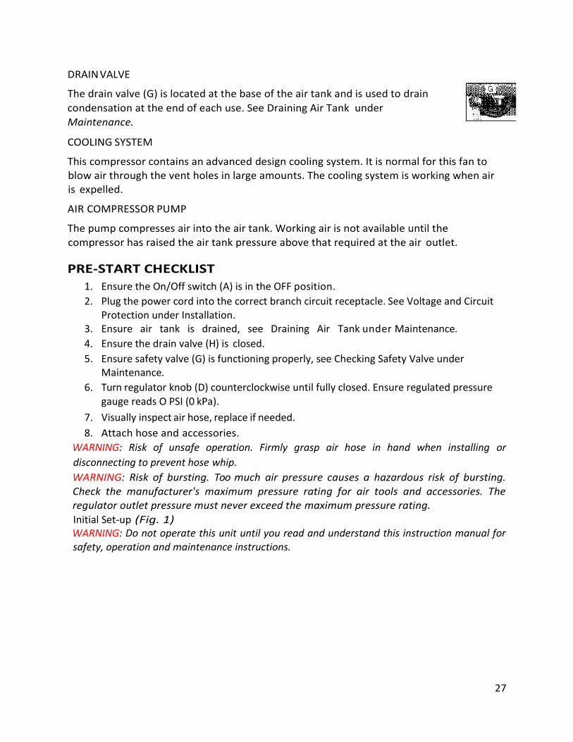
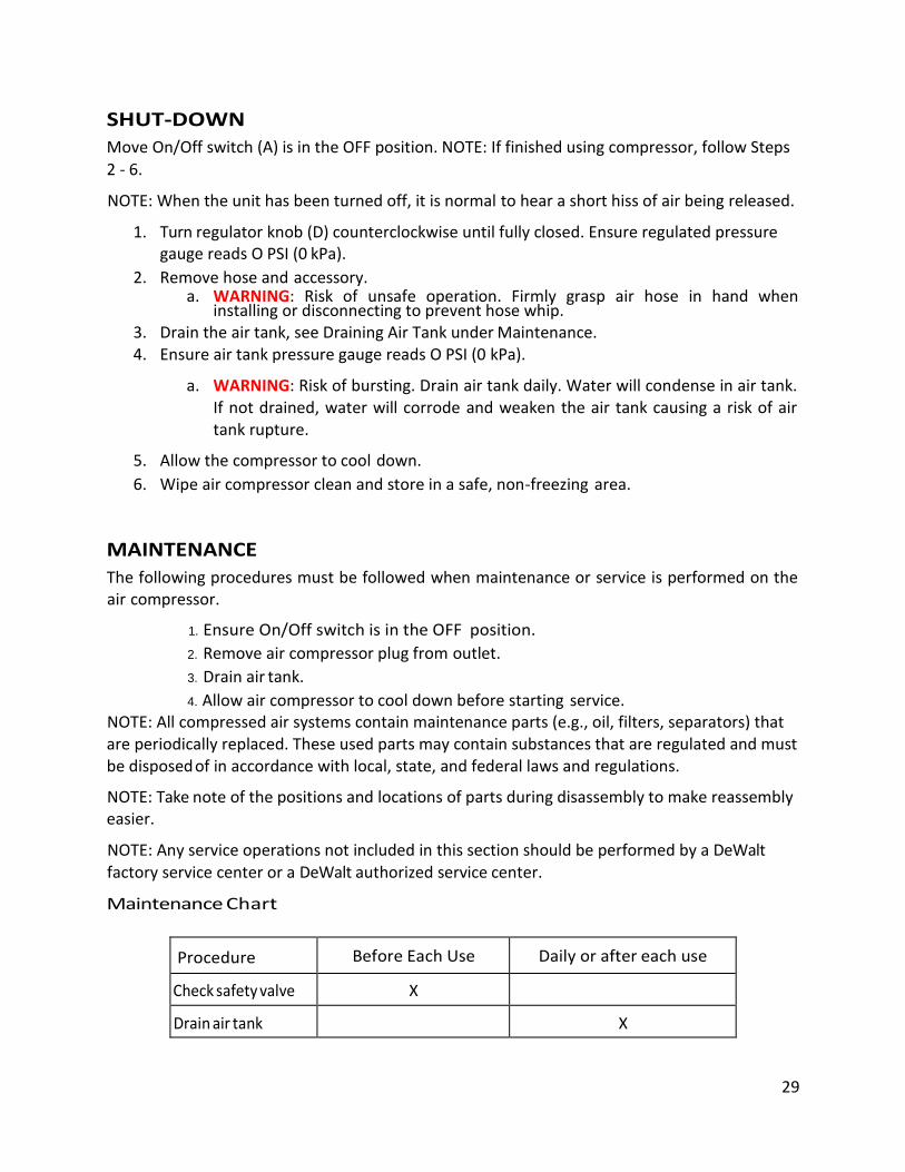
DRAIN VALVE
The drain valve (G) is located at the base of the air tank and is used to drain
condensation at the end of each use. See Draining Air Tank under
Maintenance.
COOLING SYSTEM
This compressor contains an advanced design cooling system. It is normal for this fan to blow air through the vent holes in large amounts. The cooling system is working when air is expelled.
AIR COMPRESSOR PUMP
The pump compresses air into the air tank. Working air is not available until the
compressor has raised the air tank pressure above that required at the air outlet.
PRE-START CHECKLIST
1. Ensure the On/Off switch (A) is in the OFF position.
2. Plug the power cord into the correct branch circuit receptacle. See Voltage and Circuit Protection under Installation.
3. Ensure air tank is drained, see Draining Air Tank under Maintenance.
4. Ensure the drain valve (H) is closed.
5. Ensure safety valve (G) is functioning properly, see Checking Safety Valve under Maintenance.
6. Turn regulator knob (D) counterclockwise until fully closed. Ensure regulated pressure gauge reads O PSI (0 kPa).
7. Visually inspect air hose, replace if needed.
8. Attach hose and accessories.
WARNING: Risk of unsafe operation. Firmly grasp air hose in hand when installing or
disconnecting to prevent hose whip.
WARNING: Risk of bursting. Too much air pressure causes a hazardous risk of bursting. Check the manufacturer's maximum pressure rating for air tools and accessories. The regulator outlet pressure must never exceed the maximum pressure rating.
Initial Set-up (Fig. 1) WARNING: Do not operate this unit until you read and understand this instruction manual for safety, operation and maintenance instructions.
28
BREAK-IN PROCEDURE
WARNING: Serious damage may result if the following break-in instructions are not closely followed.
This procedure is required before the air compressor is put into service for the first time and when the check valve or a compressor pump/motor has been replaced.
1. Ensure the On/Off switch (A) is in the OFF position. a. NOTE: If hose is not connected to Quick Connect body, pull coupler
back until it clicks to prevent air from escaping through the quick connect.
2. Plug the power cord into the correct branch circuit receptacle. See Voltage
and Circuit Protection under Installation.
3. Open the drain valve (counter-clockwise) fully to permit air to escape and
prevent air pressure build up in the air tank during the break-in period.
4. Move the On/Off switch to the ON position. The compressor will start.
5. Run the compressor for 15 minutes.
6. After 15 minutes, close the drain valve by turning clockwise. The tank will
fill to cut-out pressure and the motor will stop.
7. Compressed air will be available until it is used or bled off.
OPERATING PROCEDURES
Start-up (Fig. 1) 1. Follow Pre-Start Checklist under Preparation for Use.
2. Move the On/Off switch to the ON position and allow tank pressure to build. Motor will stop when tank pressure reaches cut-out pressure.
a. CAUTION: Risk of unsafe operation. Compressed air from the unit
may contain water condensation. Do not spray unfiltered air at an
item that could be damaged by moisture. Some air operated tools
or devices may require filtered air. Read the instructions for the air
tool or device.
3. Adjust regulator (D) to desired setting. See Regulator under Features.
29
SHUT-DOWN
Move On/Off switch (A) is in the OFF position. NOTE: If finished using compressor, follow Steps
2 - 6.
NOTE: When the unit has been turned off, it is normal to hear a short hiss of air being released.
1. Turn regulator knob (D) counterclockwise until fully closed. Ensure regulated pressure gauge reads O PSI (0 kPa).
2. Remove hose and accessory. a. WARNING: Risk of unsafe operation. Firmly grasp air hose in hand when
installing or disconnecting to prevent hose whip. 3. Drain the air tank, see Draining Air Tank under Maintenance. 4. Ensure air tank pressure gauge reads O PSI (0 kPa).
a. WARNING: Risk of bursting. Drain air tank daily. Water will condense in air tank. If not drained, water will corrode and weaken the air tank causing a risk of air tank rupture.
5. Allow the compressor to cool down.
6. Wipe air compressor clean and store in a safe, non-freezing area.
MAINTENANCE
The following procedures must be followed when maintenance or service is performed on the air compressor.
1. Ensure On/Off switch is in the OFF position.
2. Remove air compressor plug from outlet.
3. Drain air tank.
4. Allow air compressor to cool down before starting service. NOTE: All compressed air systems contain maintenance parts (e.g., oil, filters, separators) that are periodically replaced. These used parts may contain substances that are regulated and must be disposed of in accordance with local, state, and federal laws and regulations.
NOTE: Take note of the positions and locations of parts during disassembly to make reassembly easier.
NOTE: Any service operations not included in this section should be performed by a DeWalt factory service center or a DeWalt authorized service center.
Maintenance Chart
Procedure Before Each Use Daily or after each use
Check safety valve X
Drain air tank X
30
Checking Safety Valve
WARNING: Risk of bursting. If the safety valve does not work properly, over-pressurization may occur, causing air tank rupture or an explosion.
Before starting compressor, pull the ring on the safety valve to make sure that the safety valve operates freely. If the valve is stuck or does not operate smoothly, it must be replaced with the same type of valve.
Draining Air Tank
WARNING: Risk of unsafe operation. Risk from noise. Air tanks contain high pressure air. Keep face and other body parts away from outlet of drain. Use safety glasses when draining as debris can be kicked up into face. Use ANSI S12.6 (S3.19) ear protection as air flow noise is loud when draining.
NOTE: All compressed air systems generate condensate that accumulates in any drain point
(e.g., tanks, filter, aftercoolers, and dryers). This condensate contains lubricating oil and/or substances which may be regulated and must be disposed of in accordance with local, state,
and federal laws and regulations.
1. Ensure On/Off switch (A) is in the OFF position.
2. Move compressor into an inclined position so drain valve (H) is at the lowest point (this will assist in removing moisture, dirt, etc. from air tanks)
3. Place a suitable container under the drain valve to catch discharge.
4. Grasp black lever on drain valve.
5. Slowly rotate lever to gradually bleed air from air tank.
CAUTION: Risk of property damage. Drain water from air tank may contain oil and rust which can cause stains.
6. When air tank pressure gauge reads 1O PSI (275.1 kPa), rotate valve to the fully open position.
7. Close drain valve when finished.
31
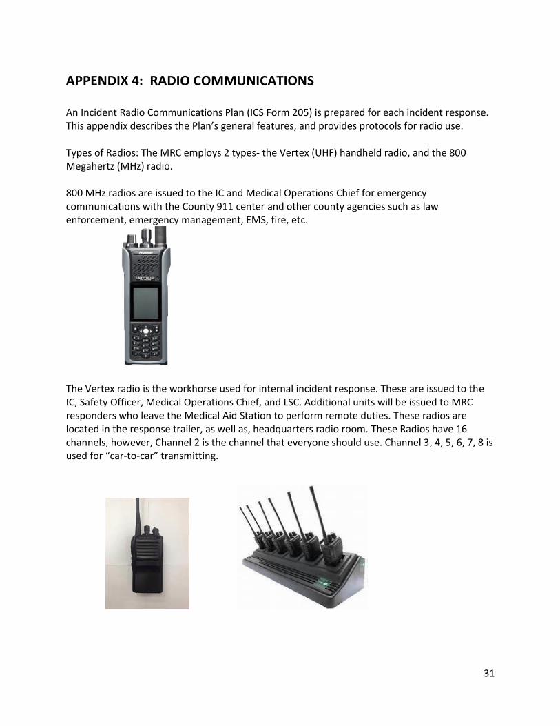
APPENDIX 4: RADIO COMMUNICATIONS An Incident Radio Communications Plan (ICS Form 205) is prepared for each incident response. This appendix describes the Plan’s general features, and provides protocols for radio use. Types of Radios: The MRC employs 2 types- the Vertex (UHF) handheld radio, and the 800 Megahertz (MHz) radio. 800 MHz radios are issued to the IC and Medical Operations Chief for emergency communications with the County 911 center and other county agencies such as law enforcement, emergency management, EMS, fire, etc.
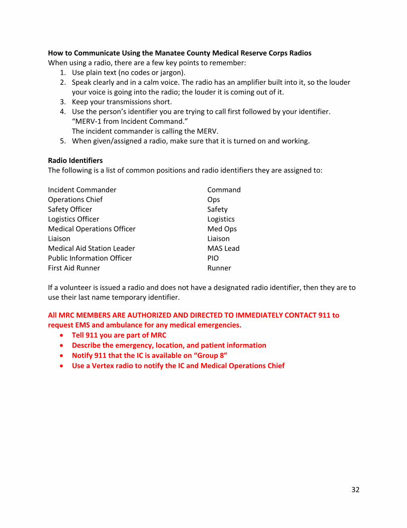
The Vertex radio is the workhorse used for internal incident response. These are issued to the IC, Safety Officer, Medical Operations Chief, and LSC. Additional units will be issued to MRC responders who leave the Medical Aid Station to perform remote duties. These radios are located in the response trailer, as well as, headquarters radio room. These Radios have 16 channels, however, Channel 2 is the channel that everyone should use. Channel 3, 4, 5, 6, 7, 8 is used for “car-to-car” transmitting.
32
How to Communicate Using the Manatee County Medical Reserve Corps Radios When using a radio, there are a few key points to remember:
1. Use plain text (no codes or jargon). 2. Speak clearly and in a calm voice. The radio has an amplifier built into it, so the louder
your voice is going into the radio; the louder it is coming out of it. 3. Keep your transmissions short. 4. Use the person’s identifier you are trying to call first followed by your identifier.
“MERV-1 from Incident Command.” The incident commander is calling the MERV.
5. When given/assigned a radio, make sure that it is turned on and working. Radio Identifiers The following is a list of common positions and radio identifiers they are assigned to: Incident Commander Command Operations Chief Ops Safety Officer Safety Logistics Officer Logistics Medical Operations Officer Med Ops Liaison Liaison Medical Aid Station Leader MAS Lead Public Information Officer PIO First Aid Runner Runner If a volunteer is issued a radio and does not have a designated radio identifier, then they are to use their last name temporary identifier.
All MRC MEMBERS ARE AUTHORIZED AND DIRECTED TO IMMEDIATELY CONTACT 911 to request EMS and ambulance for any medical emergencies.
Tell 911 you are part of MRC
Describe the emergency, location, and patient information
Notify 911 that the IC is available on “Group 8”
Use a Vertex radio to notify the IC and Medical Operations Chief
33
APPENDIX 5: VEHICLE MECHANICAL PROBLEMS
2004 Chevrolet Silverado Pickup Truck: Manatee County Asset Unit Number: 46386 License Plate: 219947
If a problem develops, pull off the road into a safe location.
Don deployment vests (stowed in a plastic bin on the trailer’s front counter).
Assess problem including situational safety.
Turn on running lights and emergency flashers.
Set parking brake and move shift lever to PARK position.
Leave engine running if it is not the problem.
In either case, raise the hood.
Remove 2 warning signs from the emergency bag in the truck. Carefully place signs 100 and 200 feet behind the vehicle, but not on the roadway.
At night or in poor visibility, deploy flares or battery powered warning lights at the signs.
Notify IC or LSC by radio or phone. State whether the problem can be fixed by the Mobile Team, and give an estimate of delay time.
DO NOT LEAVE TRAILER UNATTENDED IF TRUCK
HAS TO GO FOR HELP OR PARTS.
If County Fleet Services help is needed call 941-708-7458 Monday through Friday 7:30 am to 4:30 pm. Describe location and problem. Fleet may send NORM’S TOWING to assist.
For breakdowns after 4:30 pm or on holidays and weekends call NORM’S TOWING at 941-756-2000. Describe the situation and let them know if the MRC also trailer needs to be returned.
The MRC vehicles are to be towed to the Manatee County Field Operations Center on 26th Avenue East.
Tow receipts MUST be delivered to Fleet Services on the first work day after receiving tow services.
The driver should deliver a completed Manatee County Incident Report to your IC or MRC Coordinator as soon as possible. The one-page form is in the truck glove box. Complete this form even if there is no accident or injury.
IF THE INCIDENT INVOLVED DAMAGE OR VANDALISM also complete the 2-page Manatee County Vehicle Crash Report (in glove box). Deliver to your IC or LSC as soon as possible.
If it becomes necessary, the Health Department may have another vehicle capable of towing the trailer.
Contact the MRC Coordinator to arrange for its use.
34
APPENDIX 6: VEHICLE ACCIDENTS
1. CONSULT ACCIDENT GUIDANCE IN GLOVE BOX OF TRUCK. 2. DO NOT move truck or trailer from the accident site. 3. Assess injuries.
a. If there are complaints of injuries to employee(s) or other persons call 911 for EMS evaluation. If mobile phones are out of range or otherwise unavailable, use a Vertex to contact the IC or LSC who will notify 911 via mobile phone or 800Mhx radio. Provide first aid if you are trained to do so. Notify your supervisor and Risk Management (941-745-3750).
b. If there are no injuries, notify the police (911), your supervisor and Risk Management (941-745-3750).
4. DO NOT LEAVE THE MEDICAL AID STATION TRAILER UNATTENDED. 5. Obtain names of any witnesses and get their complete address and phone numbers. 6. Take photographs of all vehicles involved. 7. DO NOT sign any statement or discuss the accident with anyone except law
enforcement, your supervisor (IC, LSC, or MOC) or Risk Management. 8. DO NOT DISCUSS LIABILITY. 9. IMMEDIATELY send the Vehicle Accident Report to Risk Management. Always list the
County asset unit number on the report. Law enforcement will ask for your driver’s license. Also produce your MRC identity badge. If asked, the truck registration and proof of insurance are in an envelope in the glove box. The insurance proof is a white 3x6 inch card. The vehicle is self-insured by the Manatee County Board of County Commissioners, per Florida Statute 768.28.
If County Fleet Services help is needed call 941-708-7458 Monday through Friday 7:30 am to 4:30 pm. Describe location and problem. Fleet may send NORM’S TOWING to assist.
For breakdowns after 4:30 pm or on holidays and weekends call NORM’S TOWING at 941-756-2000. Describe the situation and let them know if the MRC also trailer needs to be returned.
The MRC vehicles are to be towed to the Manatee County Field Operations Center on 26th Avenue East.
Tow receipts MUST be delivered to Fleet Services on the first work day after receiving tow services.
The driver should deliver a completed Manatee County Incident Report to your IC or MRC Coordinator as soon as possible. The one-page form is in the truck glove box. Complete this form even if there is no accident or injury.
IF THE INCIDENT INVOLVED DAMAGE OR VANDALISM Complete the two-page Manatee County Vehicle Crash Report (in glove box). Deliver to your IC or LSC as soon as possible.
35
APPENDIX 7: OTHER VEHICLE ISSUES
FLAT TIRE
If Fleet Service or NORM’S TOWING is not available:
Replace a flat tire on the truck following instructions in the owner manual located in the glove box.
FIRE
For a threatening or serious fire call 911.
There are two extinguishers. One is behind the passenger seat of the truck. Another is in the trailer. If possible, someone trained in its use should operate the extinguisher.
See reporting requirements in APPENDIX 5 and APPENDIX 6.
LOST
Safely pull the rig off the road; contact LSC or IC.
Report last known location and direction taken from there.
IGNITION KEY LOCKED IN TRUCK
PLAN A
If the key came from MRC Ready Room, AND you are carrying the trailer keys on you, open the trailer and use the truck key in KEY BOX C.
PLAN B
If the key came from the trailer and a truck key is still in MRC Ready Room 65, contact IC or LSC to determine whether a courier can bring the key to you.
You may also contact MRC Coordinator David Skau (941-465-0715) or Preparedness Director Adam Dubois (941-405-7347).
PLAN C
If County Fleet Services help is needed call 941-708-7458 Monday through Friday 7:30 am to 4:30 pm. Describe location and problem. Fleet may send NORM’S TOWING at 941-756-2000 to assist.
For lock-outs after 4:30 pm or on holidays and weekends call NORM’S TOWING at 941-756-2000.
36
PUBLIC ENCOUNTERS
If an adverse public encounter occurs while traveling to or from an incident response, explain the mission and refer them to the Public Information Officer (for large incidents) or the IC or LSC (for smaller incidents).
ONLY when the response is part of an emergency situation, and a public encounter is preventing the MRC mobile unit from reaching the incident, contact the MRC Coordinator or IC. Explain the situation, report your location, and ask for assistance from law enforcement.
37
APPENDIX 8: TRAILER CANOPY
Trailer Canopy roll-out:
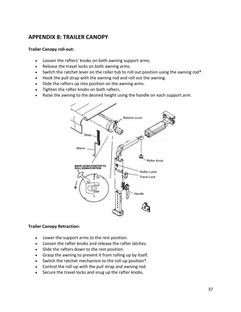
Loosen the rafters’ knobs on both awning support arms. Release the travel locks on both awning arms. Switch the ratchet lever on the roller tub to roll out position using the awning rod*. Hook the pull strap with the awning rod and roll out the awning. Slide the rafters up into position on the awning arms. Tighten the rafter knobs on both rafters. Raise the awning to the desired height using the handle on each support arm.
Trailer Canopy Retraction:
Lower the support arms to the rest position. Loosen the rafter knobs and release the rafter latches. Slide the rafters down to the rest position. Grasp the awning to prevent it from rolling up by itself. Switch the ratchet mechanism to the roll-up position*. Control the roll-up with the pull strap and awning rod. Secure the travel locks and snug up the rafter knobs.
38
*A sticking awning ratchet lever is common with new awnings because everything is new and the springs that roll up the awning are especially stiff.
Try using your other hand to pull down... just a little... on the awning support arm while releasing the awning lever. This works best when the awning is out but you can also do it when the awning is rolled up.
Pulling down on the support arm helps release to ratchet attached to the other end of the lever. The ratchet is what locks the awning in or out and which way you pull the lever is what controls the ratchet direction.

39
APPENDIX 9: GENERATORS
CAUTION: GENERATORS POSE LIFE-THREATENING HAZARDS OF FIRE, ELECTROCUTION, AND CARBON MONOXIDE POISONING.
REFER TO THE OWNER’S MANUAL FOR ALL ASPECTS OF GENERATOR USE.
The generator manual is in the black file cabinet inside the trailer.
GENERAL GUIDANCE
UNLOADING - The LSC will decide the number of units to unload. Usually, two units are deployed and one is kept in reserve. Uncover the units and remove tie-down straps. Stow covers and straps. Units are heavy and should be moved by two people. Roll the units to and down the rear ramp. INCLEMENT WEATHER - Units are not meant to run in the rain. Use an extra tent to provide cover. Set up the tent before moving units from the trailer. DEPLOYMENT - The LSC and Safety Officer will decide on generator location, considering wind direction, noise, security, etc. Roll the units across pavement. To move units over unpaved ground enlist assistance and move units with the red cart. Units are to be set on the ground as level as possible. SAFETY/SECURITY - Before units are used, establish a safety/security perimeter using barricades, cones, caution tape, etc. One side of the truck can form a border. FUEL MANAGEMENT - All generator fuel tanks remain on the truck until needed. If the truck is needed for other duty, top off generator fuel tanks as needed and keep a backup supply nearby, in safe place. PARALLEL OPERATION - Parallel operation is two or more units connected to provide more power. The LSC will determine whether two generators need to run, and supervise the parallel connection process. MEDICAL SERVICES SUPPORT - Generators provide energy for trailer lights, flood lights, radio charging panels, air-conditioners, refrigerated cooler, and other essential devices. One connector between the generator(s) and trailer will provide all current needed for devices within the trailer. Some outlets inside the trailer can be used to power devices in the Medical Aid tent or near the station. Other large users of power, like the portable Halogen work lights, should be powered directly from the generators, using extension cords. LOADING - Turn off the generators as soon as ordered to begin loading- the units need time to cool. When cool, return units to the trailer, tie them down, and cover them. Account for all extension cords, security measures, the tent, fuel tanks, etc.
40
OPERATING THE GENERATORS
PREPARATION - Lay out the power cord connected to the trailer. Use the building cord as an extension if needed, but do not connect either to the generator. Clean all cooling holes on the side panel, control panel, and bottom of the unit, but do not lay the unit on its side.
ELECTRIC LOAD - Limit maximum power (3.0 kVA) to 30 minutes. For continuous use do not exceed rated power (2.8kVA). This is not a setting; it is the total demand placed on the unit by devices.
STARTING
1. Make sure no cords or devices are connected to the generator. 2. Check that fuel tank is full and turn the fuel lever to ON. 3. To start a cold engine, pull the choke knob out to the CLOSED position. To
start a warm engine, leave the choke knob in the OPEN position. 4. Turn the engine switch to START position and hold it there for 5 seconds or
until the engine starts. If it fails to start after 5 seconds, stop trying. Release the switch and wait 10 seconds before trying again.
5. When the engine starts allow the engine switch to return to the ON position. 6. If the starting engine speed drops during repeated tries the battery should be
recharged. 7. If the choke knob was moved to CLOSED, gradually push it to OPEN as the
engine warms. 8. Check to see that the Output Indicator Light is green, and that neither the
Overload Indicator Light nor Oil Alert System Light is on. 9. To use the EcoThrottle system, turn the EcoThrottle switch to ON after the
engine has warmed for 3 minutes. This system slows the engine when load decreases.
For manual starting instructions refer to the user’s manual, page 36. POWERING UP THE STATION - While one person remains to monitor the generators, connect the trailer power cord or matching extension cord to the 120V 20A AC receptacle. Turn on devices (lights, air conditioner, portable refrigerator, etc.) DO NOT use the DC receptacle, which should only be used for charging 12-volt automotive type batteries. Use the chargers in the trailer, instead. DOUBLE-CHECK THE GENERATOR(S)
The red Overload Indicator Light will come on if the unit is overloaded; if there is a short circuit in a connected device, or if the inverter is overheated.
41
The red light will stay ON for five seconds and then current will shut of automatically.
The green Output Indicator Light will go OFF.
Determine the problem by testing each device individually and then together. Correct the problem.
MONITOR THE GENERATORS
The Safety Officer will monitor the generator area to prevent unauthorized access.
The LSC will check system performance (as above) on an hourly basis. Fuel status will also be monitored hourly.
REFUELING
With the engine stopped, check the fuel level gauge. Refuel if the level is low.
Allow the engine to cool.
Refuel carefully to avoid spilling fuel.
Do not fill above the fuel strainer shoulder.
Tighten the fuel tank cap securely.
STOPPING
To stop in an emergency turn the engine switch to OFF.
In normal use turn off all devices and unplug the trailer or extension cords from the unit.
Turn the engine switch to OFF.
Turn the fuel valve lever to OFF.
WHEN A GENERATOR WILL NOT RUN OR CHARGE
See troubleshooting on pages 61-62 of the User Manual. If the problem cannot be resolved, replace the unit with the backup generator.
For protracted Incident Responses, have the IC request County Fleet Services support.